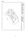
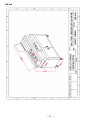
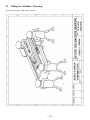
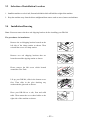
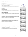
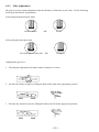
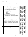
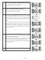
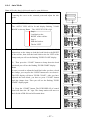
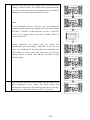
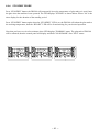
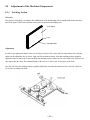
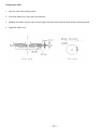
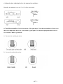
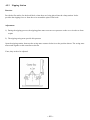
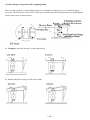
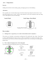
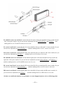
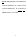
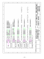
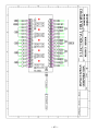
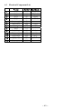
1
Instruction Manual
PERFECT BINDER
MODEL: DB-280, DB-200, DB-660, DB-700
Duplo Taiwan Corporation
TEL:886-2-27212117
FAX:886-2-27211669
8F., NO.2, SEC.4, CHUNG HSIAO E.RD., TAIPEI,TAIWAN
~ 1 ~ Table of Contents
Page
0.
Cover/Table Of Contents
2
1.
SAFETY INSTRUCTION
8
1.1
SAFETY REGULATION
9
1.2
WARNING PLATE
11
1.3
LOCATION OF SAFETY SIGNS ON THE PRESS BRAKE IS SHOWN IN THE
FIGURE BELOW
12
1.4
NAME PLATE
13
2.
SPECIFICATION
14
2.1
14
2.2
SPECIFICATION
MACHINE NOISE
2.3
FUNCTION OF THE MACHINE
17
2.4
LEGEND OF THE MACHINE
18
2.5
MACHINE DIMENSION
19
3.
INSTALLATION
23
3.1
SAFETY RULES FOR MACHINE MOVEMENT
23
3.2
LIFTING THE MACHINE/DRAWING
24
3.3
SELECTION OF LOCATION
25
3.4
INSTALLATION / DRAWING
25
3.5
INSTALLATION AND LEVELING
26
3.6
POWER SUPPLY REQUIREMENT
26
3.7
CONNECT POWER SOURCE WIRES
26
3.8
CHECK CONNECTION OF POWER WIRES
27
4.
OPERATION
28
4.1
OPERATOR POSITION DRAWING
28
4.2
CONTROL PANEL
29
4.3
EMERGENCY STOP
30
4.4
OPERATION PROCEDURE
31
4.5
ADJUSTMENT OF THE MACHINE/PARTS
44
5.
MAINTENANCE
55
5.1
DAY/WEEK/MONTH/YEAR MAINTENANCE
55
5.2
LUBRICATION
55
5.3
TROUBLE SHOOTING
56
5.4
TEST OF SAFETY DEVICES
59
6.
ELECTRIC
61
6.1
SAFETY RULES FOR ELECTRICAL CONTROL SYSTEM
61
6.2
ELECTRICAL DRAWING
62
6.3
ELECTRICAL PART LIST
69
16
~ 2 ~ ~ 3 ~ ~ 4 ~ ~ 5 ~ ~ 6 ~ ~ 7 ~ 1 Safety Instruction General Safety Regulation
Warning Be careful of the following items that may cause injury or damage.
•Do not place tiny items on top of the machine to avoid dropping them into the machine.
•Pay close attention to the warning signs on the machine that indicates a dangerous or “no-touch” area of the
machine.
•Keep hands and fingers away from glue tank and notching station.
•Use only the suggested hot melt glues with the following characteristics:
Application temperature: 260 F (126.67 ℃) to 290F (143.33 ℃) Working Glue Viscosity:
3,800 to 7,250 CPS
•Duplo is not responsible for the quality of the binding that is produced by the non-suggested glues.
In case of thermostat failure :
DB-280 has implemented the secondary thermostat to protect the glue tank temperature over 410F (210。C).
When it occurs, the power of DB-280 will be automatically turned off. You have to wait for the glue tank to
cool down before you can restart the machine. If this problem occurs again, call your authorized dealer for service.
~ 8 ~ 1.1
Safety Regulation
•KNOW YOUR MACHINE. For your own safety, read the owner's manual carefully. Learn its application and limitations as well as
specific potential hazards pertinent to this machine.
•KEEP GUARDS IN PLACE AND IN WORKING ORDER. •REMOVE ADJUSTING KEYS AND WRENCHES. For habit of checking to see that keys and adjusting wrenches are remove from the machine before turning
it on. •KEEP WORK AREA CLEAN. Cluttered areas and benches invite accidents. •DO NOT USE IN DANGEROUS ENVIRONMENTS. Do not use power tools in damp or we locations, or expose them to rain. Keeps work area well illuminated. •KEEP CHILDREN AWAY. All visitors should be kept at a safe distance from work area. •MAKE WORKSHOP CHILDPROOF. With padlocks, master switches, or by removing starter keys. •DO NOT FORCE THE MACHINE. It will do the job better and be safer at the rate for which it was designed. •USE THE RIGHT TOOLS. Do not force the machine or attachments to do a job for which they were not designed. •WEAR PROPER APPAREL. Avoid loose clothing, gloves, neckties, rings, bracelets, or jewelry, which could be caught in moving parts.
Nonslip footwear is recommended. Wear protective hair covering to contain long hair. •SECURE WORK. Use clamps or a vice to hold work when practical. It is safer than using your hand and frees both hands to
operate the machine. •DO NOT OVERREACH. Keep proper footing and balance at all times. •MAINTAIN MACHINE IN TOP CONDITION. Keep machine clean for best and safest performance. Follow instructions for lubricating and changing
accessories. •DISCONNECT MACHINE FROM POWER SOURCE. Before servicing and when changing accessories, or when mounting and remounting motor. •USE RECOMMENDED ACCESSORIES. Consult the owner's manual for recommended accessories. •NEVER LEAVE MACHINE RUNNING UNATTENDED. TURN POWER OFF. ~ 9 ~ •Protective guards and shields must be in place at all times unless that specific part requires servicing.
•Never clean or remove chips while the machine is running. •Do not remove or alter warning labels and replace any that become obscured. Warranty If any part is proved to be defective within ONE YEAR from the date of purchase then the manufacturer
or distributor shall repair or replace the part provided the defective part is returned immediately to the
manufacturer or distributor.
The manufacturer or distributor shall have no obligation to repair or replace those parts failing due to
operator carelessness, misuse or due to any cause such as parts failing due to poor lubrication,
inadequate cleaning, improper operating environment, improper utilities or operator error. ~ 10 ~ 1.2
Warning Plate This machine has warning symbols attached on it as shown below to ensure proper and safe operation.
These symbols are used on the machine to indicate points or instances of specific danger to operating
personnel. Make sure to memorize these symbols and bring them to the attention of others as and when
necessary. Do not remove safety symbols from the machine. Electrical shock
Hand Crush/Force from two sides
Cutting of fingers or hand rotating blade
Hand Crash/ force from side
Burn Hazard/Hot Surface
Cutting of fingers or Hand/moving part
Consult service manual
~ 11 ~ 1.3
Location of safety signs on the press brake is shown in the figure below ~ 12 ~ 1.4
Name Plate ~ 13 ~ 2
Specification 2.1 Specification Model
DB-280
12.6” x 15.75” ( 320mm x 400mm )
Maximum Book Size
Minimum Book Size
3.15” x 1.97” ( 80mm x 50mm )
Maximum Binding Thickness
1.6” ( 40mm )
Glue Warm Up
40 minutes ( varies depending upon glue type )
Glue Warm Up in Stand-by Mode
5 minutes
Cycle Speed
360 cycles per hour
Production Speed
Up to 200 books per hour
Power Source
110V, 60 Hz ( Option: 220V, 50 Hz )
Power Consumption
10 Amps.
Machine Weight
262
Machine Dimension
49.2”(L) x 22”(W) x 18.5”(H)
(1250x560x470mm)
lbs ( 119 Kg )
Model
DB-200
12.6” x 15.75” ( 320mm x 400mm )
Maximum Book Size
Minimum Book Size
3.15” x 1.97” ( 80mm x 50mm )
Maximum Binding Thickness
1.6” ( 40mm )
Glue Warm Up
25 minutes ( varies depending upon glue type )
Glue Warm Up in Stand-by Mode
5 minutes
Cycle Speed
360 cycles per hour
Production Speed
Up to 200 books per hour
Power Source
220V/240V, 50 Hz
Power Consumption
10 Amps.
Machine Weight
255
Machine Dimension
45.3”(L) x 22”(W) x 14.5”(H)
(1150x560x370mm)
lbs ( 116 Kg )
~ 14 ~ Model
DB-660
11.7” x 15.53” ( 297mm x 420mm )
Maximum Book Size
Minimum Book Size
5.7” x 5.51” ( 145mm x 140mm )
Maximum Binding Thickness
2.3” ( 60mm )
Glue Warm Up
40~50 minutes ( varies depending upon glue type )
Glue Warm Up in Stand-by Mode
5 minutes
Cycle Speed
570 cycles per hour
Production Speed
Up to 200 books per hour
Power Source
110V, 60 Hz ( Option: 220V, 50 Hz )
Power Consumption
10 Amps.
Machine Weight
210~230 Kg ±3 Kg
Machine Dimension
54.3”(L) x 25.6”(W) x 40.9”(H)
(1380x650x1040mm)
Model
DB-700
11.7” x 8.26” ( 297mm x 210mm )
Maximum Book Size
Minimum Book Size
5.7” x 5.51” ( 145mm x 140mm )
Maximum Binding Thickness
1.57” ( 40mm )
Glue Warm Up
40~50 minutes ( varies depending upon glue type )
Glue Warm Up in Stand-by Mode
5 minutes
Cycle Speed
620 cycles per hour
Production Speed
Up to 200 books per hour
Power Source
110V, 60 Hz ( Option: 220V, 50 Hz )
Power Consumption
10 Amps.
Machine Weight
Machine Dimension
250~270 Kg ±3 Kg
78.7”(L) x 43.3”(W) x 25.6”(H)
(2000x1100x650mm)
~ 15 ~ 2.2 Machine Noise
DECLARED NOISE EMISSION VALUES in accordance with ISO 7960.
Operating
Declared A-weighted Sound Power Level,
Lward, in dB re 1 pW
81.8
Declared A-Weighted Emission Sound
Pressure Level , lpAd , in dB re 20 μPa , at
the operator’s position.
68.8
The values are determined according to specific test code ISO 3746.
The figures quoted are emission levels and are not necessarily safe work levels, whilst there is a correlation
between emission and the exposure level. This cannot be used reliably to determine whether or not further
precautions are required. Factors that influence the actual level of exposure of work piece include the
duration of noise. (i.e. The number of other adjacent machines). Also, the permissible exposure levels can vary country to country. The information, however, will enable the
machine user to make a better evaluation of hazard and the risk. ~ 16 ~ 2.3 Function of the Machine 1. Provided a flat surface for the book block, when there are being placed into the clamp station. It also provides
the nipping force to form the cover around the spine of the book. 2. Holding the book block for the notching, gluing, and nipping processes of bookbinding. 3. Provides driving power to move and locate the clamp station over the glue drum and notching station, then return
it back to the nipping station for covering and binding. ~ 17 ~ 2.4
Legend of the Machine Drawing ~ 18 ~ 2.5
Machine Dimension Drawing DB-280
~ 19 ~ DB-200
~ 20 ~ DB-660
~ 21 ~ DB-700
~ 22 ~ 3 Installation 3.1 Safety Rules for Machine Movement SETTING THE MACHINE IN PLACE •The haulage of the machine to the installation place is done with the crane or forklift. •Before unloading the machine, conduct a complete inspection of any damage which might have been
caused during transportation. •Before placing the machine on the production floor, make sure that the floor base is thick and strong
enough to endure mechanical vibration and to support the weight of the machine for a long time. •Allow enough room around the machine for auxiliary production equipment for the maintenance of the
machine. •Use haulage equipment with sufficient strength for the machine weight. (Such as a crane, forklift, wire
ropes, and hooks)As for machine size, make sure the specifications table. •When looping the wire ropes, put pads between the wire ropes and the machine body at the places where
the wire ropes contacts the machine body so that the machine will not get damage. specifications table about haulage:
Variant NO.
Basic
Variant Identification
Unit
DB-280
Environment temperature
°C
+0°C~+40°C
Environment humidity
%
85%
Machine size (L.W.H)
mm
1250x560x470
Machine weight
kg
119
Center-of-gravity position (L.W.H)
mm
1250x560x470
Min. room for setting place (L.W.H)
mm
1250x560x470
~ 23 ~ 3.2 Lifting the Machine / Drawing At least four people to lift up the machine ~ 24 ~ 3.3 Selection of Installation Location 1. Install the machine on a level safe, firm and solid table which will hold the weight of the machine.
2. Keep the machine away from the direct sunlight and heat sources such as stoves, heaters and radiators.
3.4 Installation/Drawing
Note: You must remove the three red shipping brackets before installing your DB-280
The procedures for installation:
Remove the red shipping bracket located on the
left side of the clamp station as shown. Then
reinstall the screws in clamp station.
Remove two red shipping brackets that are
located around the nipping station as shown.
Please remove the M6 screw which located
around the Glue Tank
Lift up your DB-280, slide in the bottom cover
first. Then slide in the glue draining tray
underneath the glue tank as shown.
Place your DB-280 on a safe, firm and solid
table. Then mount the cover-sheet holder to the
right side of the machine as shown.
~ 25 ~ 3.5 Installation and Leveling
3.5.1
Tools: adjust screw by screwdrivers ,
Allen wrench
3.5.2
The main machine is calibrated by level gauge to hundredth precision
3.6 Power Supply Requirement
Insufficient voltage from factory power source may affect the power output of the motor and the function of
the controller.
It is important to connect this machine to the correct voltage in the factory power source. Use only an
independent power source.
Table for power supplies requirement:
3.7
Model
Kw
Voltage
Current
Breaker capacity
Wire size
DB-280
9.7Kw
220V
13A
50A
2.08mm²
DB-200
9.7Kw
220V
13A
50A
2.08mm²
DB-660
1.75kw
220V
15A
50A
2.08mm²
DB-700
1.80kw
220V
18A
50A
2.08mm²
External Power Connection
1. Connect the machine to a dedicated power outlet. Never connect the machine to a power outlet servicing other
appliances or electrical devices.
2. Place the machine close to the power outlet. Do not use extension cords. Use the machine only where voltage is
relatively constant.
3. The range of power supplies for proper operation of the machine.
Tolerance of power supply: LOCAL VOLTAGE 110V or 220V 10%
Frequency fluctuation: 110 V @ 60Hz 10% or 220V @ 50Hz 10%
~ 26 ~ 3.8
Check Connection of Power Wires
After the power wires have been connected it is necessary to check if the power wires are connected to the
correct connection points.
Check periodically to ensure the following :
The plug is not excessively hot
The power cord is not damaged
The plug is firmly plugged into the outlet
~ 27 ~ 4
4.1
Operation
Operator Position (Drawing)
~ 28 ~ 4.2 Control Panel
~ 29 ~ No.
Name
Description
LED Display /
Example
1
EMERGENCY
Stop all the actions of the machine. Except
when “HOT” shows on the LED DISPLAY.
“STOP” (flashing)
2
STAND BY /
LED
Temporarily lowers the temperature of glue
tank so it won’t burn the glue when the
machine is not operated.
STBY00
3
CLOSE
Close clamp.
4
LED DISPLAY
The amount of books bound.
____100
1)The amount of books bound.
2) Operating status.
BIND
3) Perform self-test and stir
glue.
the hot melt
S-TEST
4) Error messages.
ERR = L1
5
CLEAR
Clear the display counter for books bound.
____0
6
TAPE
Tape Mode, LCD display “TAPE MODE”
___25
7
START / LED
Indicates the “START” button is ready for
proceeding to the next operation.
8
OPEN
Open clamp.
9
FUNCTION /
LED
Select one of the function modes MANUAL, AUTO, or PAD.
10
NOTCH / LED
Select the notching function during the
bookbinding operation.
4.3
One of the mode
indicators will be lit.
Emergency Stop
When the emergency and Safety function is started, the machine will be stopped immediately and reset all
commands, the motor is stopped too. During machining, if any malfunction occurs, press this switch to stop
all motion. When restarting machine remember to turn this switch to the right to release it.
~ 30 ~ 4.4 Operation Procedure
(Using the DB-280)
START UP:
Turn ON the power switch of DB-280 as shown.
( where “I” for ON; “O” for OFF )
The heater of DB‐280 will automatically heat the glue to the preset working temperature and display the status of the heating processes.The 4 leftmost spaces of LED: the status of
heating process ( COLD, WARM, or HOT ).The 2 rightmost spaces of LED: The elapsed
time of heating. Start melting the glue.
The status is COLD and the elapsed time is one minute for this example as
shown.
Melting glue is processing.
The status is WARM and the elapsed time is 10 minutes for this example as
shown.
After heating for a while, the glue temperature has reached HOT status. The
elapsed time is 25 minutes for this example as shown.
When the glue temperature has reached the working temperature, DB-280
performs the self-test and stirs the melting glue.
DB-280 is ready for bookbinding and set to MANUAL mode for your
desired operation. At this moment, the control panel will display and flash
"LOAD BOOK" for your attention.
For binding operations, please refer to the MANUAL, AUTO and PAD operations.
~ 31 ~ 4.4.1
Glue Adjustment
The glue level may require adjustment when the thickness of the book or pad varies. Use the following
book spine illustrations for guidelines.
• Increasing the holt-melt glue when
Hollow middle
OR
Round
• Decreasing hot-melt glue when
Too much glue on both sides OR
Nail head
Adjusting the glue level :
1. Turn the glue adjustment lock knob counter clockwise to loosen.
2. Increase the amount of glue by sliding the knob to the right at the appropriate position.
MIN
MAX
3. Decrease the amount of glue by sliding the knob to the left at the appropriate position.
MIN
MAX
~ 32 ~ 4. Turn the knob clockwise to lock the setting
Note that the thickness of the cover sheet is an important factor for you to make a good spine. Use only
the suitable thickness of the cover sheet associated with the appropriate glue-meter position to make a
good book.
~ 33 ~ 4.4.2
Replenishing Glue Tank
CAUTION: Great care must be taken when handling hot molten glue.
Be sure not to place an excessive amount of glue in the tank at one time. Keep it at such a level that the
glue will not go over the redline in the tank while the application drum is rotating. This will prevent glue
from spilling out of the tank
Glue Replacement
1. Warm up the DB-280 as described in the STARTUP section on page 5.
2. Make sure the draining tray is warped by Aluminum foil and positioned underneath the glue tank so that
the tank drains into it.
3. Use the 6 mm Allen wrench to loosen (Counter Clockwise) the glue drain Allen screw, which is located
on top of the glue tank.
Do not attempt to remove the draining tray until the glue cools down.
4. Close (Clockwise) the glue drain Allen screw when the glue stops flowing.
5. Add new glue to the glue tank. Be sure to keep the glue level not going over the red line.
6. Remove the glue drain tray and discard the cold drained glue.
Note that it’s not necessary to drain the glue frequently if the machine is used constantly under normal
working conditions. However, in case the glue has been left unused for a long period of time with the unit in
the “ON” position, and the quality is found to be unacceptable, use the glue replacement procedures or call
your authorized dealer.
~ 34 ~ 4.4.3 Manual Mode
After the “STARTUP” procedures, the DB-280 will automatically set itself MANUAL operation and
flashing "LOAD BOOK" display. Note that the “NOTCH” LED is ON.
1 (1) Press the “OPEN” button and place the book block inside
the clamps. Be sure to follow the label instructions on the
clamp to load the book block to the RIGHT of the red line,
then slide the book block to the far LEFT of the clamps and
you will see the flashing "PUSH CLOSE" display.
Step 1:
Load book to the
RIGHT of the red line.
Step 2:
Slide the book to
The far LEFT.
(2) Then press the “CLOSE” button to clamp down the book
block and you will see the flashing "PUSH START" display.
Note:
In case you need to adjust the book block after you have closed
the clamps, you can press the "OPEN" button twice to release it.
The LED display will show "PUSH CLOSE". After you have
adjusted the book block, you have to press "CLOSE" button until
the clamps close. Then you will see the flashing "PUSH START"
display again.
(3) Press the “START” button. The LED display of control
panel will show a “Å” sign and the clamp station will move
over the notching station for notching.
~ 35 ~ After the first notching process, the clamp station will remain to
the left side of DB-280 and the LED display of the control panel
will display and flash "LOAD COVER".
2
3
4
Center the cover sheet and adjust the side guide:
Measure the width of the book plus half the thickness of the
spine. Then set side guide accordingly.
Place the cover on the nipping station, the “START” LED will
be lit and flashing "PUSH START". Then press the “START”
button to move the clamp station over the nipping station
starting the binding process for the book block and cover sheet.
Note:
If you accidentally remove or drop the cover sheet during the
clamping station returning to the nipping station, the control
panel will show “COVER?”. At this moment, you have to place
the cover on the nipping station and press "START" button to
resume the process.
5
When the display indicates “PUSH OPEN”, press the “OPEN”
button to open the clamps. Then, remove the finished book from
the right end of the clamp station.
Having completed one bound book, the LED display of control
panel will count once for the total binding amount as shown.
Then the control panel will display and flash "LOAD BOOK"
for binding next book.
6
Repeat step 1 to 5 for more books in “MANUAL” operation.
~ 36 ~ 4.4.4
Auto Mode
Note: All books done in this mode must be same thickness.
1
In the MANUAL mode, make one book.
Centering the cover to the centered point and adjust the side
guide.
2
Press “FUNCTION” button to switch to “AUTO” operation.
The “AUTO” LED will be lit and display flashing "LOAD
BOOK" as shown. Note:
3
The “NOTCH” LED is ON.
Step 1:
Load book to the
RIGHT of the red line.
Step 2:
Slide the book to
The far LEFT.
(1) Press the “OPEN” button. Be sure to follow the label
instructions on the clamp to load the book block to the RIGHT
of the red line, then slide the book block to the far LEFT of the
clamps and you will see the flashing "PUSH CLOSE" display.
(2) Then press the “CLOSE” button to clamp down the book
block and you will see the flashing "PUSH START" display.
Note:
In case you need to adjust the book block after you have closed
the clamps, you can press the "OPEN" button twice to release it.
The LED display will show "PUSH CLOSE". After you have
adjusted the book block, you have to press "CLOSE" button
until the clamps close. Then you will see the flashing "PUSH
START" display again.
(3) Press the “START” button. The LED DISPLAY of control
panel will show the “Å” sign. The clamp station will move to
the left side of DB-280 and will remain there.
~ 37 ~ 4
Place the cover sheet onto the nipping station when the display
flashing "LOAD COVER". The clamp station will automatically
move back to the position above the nipping station and start the
binding process for the book block and cover sheet.
Note:
If you accidentally remove or drop the cover sheet during the
clamping station return to the nipping station, the control panel
will show “COVER?”. At this moment, you have to place the
cover on the nipping station and press "START" button to
recover the process.
Having completed one bound book, the clamp will
automatically open and display "UNLOAD" so that you can
remove the finished book from the right end. Meanwhile, the
LED display of control panel will count once for the total
binding amount as shown. The DB-280 will flash "LOAD
BOOK" display.
5
Place the same thickness of book block onto the clamp as the
label instructions on the clamp. The clamp station will
automatically clamp down the book block and move to the left.
Repeat step 5 to 4 for more books in “AUTO” operation.
~ 38 ~ 4.4.5 PADDING MODE:
“PAD” is one of the DB-280 operations that apply to special binding applications such as binding without
cover sheet.
1
Press “FUNCTION” button to switch to “PAD” operation. The
“PAD” LED will be lit and display flashing "LOAD PAD" as
shown.
Note:
The “NOTCH” LED is normally OFF. But you can press
“NOTCH” button to actuate it, if desired.
2
(1) Press the “OPEN” button. Be sure to follow the label
instructions on the clamp To load the pad block to the
RIGHT of the red line, then slide the pad block to the far
LEFT of the clamps and you will see the flashing "PUSH
CLOSE" display.
Step 1:
Load book to the
RIGHT of the red line.
Step 2:
Slide the book to
The far LEFT.
(2) Then press the “CLOSE” button to clamp down the pad
block and you will see the flashing "PUSH START" display.
Note:
In case you need to adjust the pad block after you have closed
the clamps, you can press the "OPEN" button twice to release it.
The LED display will show "PUSH CLOSE". After you have
adjusted the pad block, you have to press "CLOSE" button until
the clamps close. Then you will see the flashing "PUSH
START" display again.
3
(1) Press the “START” button. The LED display of control
panel will show a “Å” sign and the clamp station will move
over the notching station and return to clamp station.
~ 39 ~ (2) Having moved to the left position of DB-280, the clamp
station will automatically move back to the right position and
display "WAIT..".
(4) Wait for a few seconds until the LED display of control
panel displays “PUSH OPEN” as shown.
4
Then press the “OPEN” button to open the clamp so that you
can withdraw the bound pad block. Meanwhile, the LED display
of control panel will count once for the total binding amount.
Then the control panel will display and flash "LOAD PAD" for
padding next pad.
Note:
If glue is too thick on spine, adjust thickness in accordance with
(G) Glue Adjustment.
5
Repeat step 2 to 4 for more books in “PAD” operation.
~ 40 ~ 4.4.6 STANDBY MODE
Press “STANDBY” button, the DB-280 will temporarily lower the temperature of glue tank so it won’t burn
the glue when the machine is not operated. The LED displays "STBY00" as shown below. Where "00" is the
timer display for the duration of the standby period.
Press “STANDBY” button again when the “STANDBY” LED is on, the DB-280 will reheat the glue tank to
the working temperature, then the “READY” LED will be lit and waiting for your desired operation.
Note that you have to wait a few minutes when LED displays "WARM00" status. The glue tank of DB-280
will be reheated, then the control panel will display and flash "LOAD BOOK" after "HOT" status.
~ 41 ~ 4.4.7
TAPE MODE
1
BEFORE USING TAPE MODE
INSTALL FOUR OPTIONAL BLOCK
PARTS.
Press “TAPE” button,LED Display
2
“TAPE”
“MODE"instead
of ”LOAD”“BOOK”
After clamp station goes to left,LED
display shows ”LOAD” “TAPE”
Press “START” after putting tape,
book go back right side then finish the
tape mode
ATTENTION:
It’s same operation in manual or auto
mode,please put tape in right postion
then press “START”
3
TR1 SETTING Press “START” and
“TAPE” together,set TR1 only.
This function is available in manual,
auto and pad mode.
The Nipping timer default 4 sec.
TR1 range is 2.0-10sec.
~ 42 ~ 4.4.8
CASING UNIT CONTROL
The casing unit is used for adjusting the distance between book sheets and hard cover, adjusting range
0~10mm Tuning angle 0~180degrees
Release the M4 screw first, after
4.4.9
adjusting tight the M4 screw.
VACUUM DUST REMOVAL SYSTEM
When blade cutting,it brings paper dust, so use vacuum dust removal system to clean.
The vacuum pipe size :4”
4.4.10 THE BRUSH
ATTENTION : DO NOT PUT HANDS CLOSE TO GLUE TANK
~ 43 ~ 4.5 Adjustment of the Machine/Components
4.5.1
Notching Station
Function
The purpose of notching is to enhance the solidification of the bookbinding. The notching blade makes numerous
cuts on the spine of the book so that the melted glue can penetrate the binding area.
Inner Pages Cuts Hot‐Melt Glue Adjustment
In order to get appropriate depth of the cuts and the precision of the center path for clamp station, the notching
station can be adjusted to the up, down, right, and left positions as shown. Note that notching surface should be
adjusted evenly on both sides to prevent tilting the notching surface. Otherwise, the cuts of the book will have one
side deeper than the other. The standard depths of the cuts are 1 mm evenly on the spine of the book.
You also can lift up the notching station to gain the depth of the cuts when the blade has been worn out a little bit.
Or you have to change the blade.
~ 44 ~ Changing the blade
1. Open one side of the notching station
2. Loosen the blade screw and remove the old blade
3. Install the new blade as shown, then set the height of the blade about 3mm above the surface of notching wheel
4. Tighten the blade screw
~ 45 ~ 4.5.2
Glue Tank
Function
Providing a layer of melted glue on the spine of the book so that cover and pages can be bound together .
The glue scraper of glue tank controls the quantity of the melted glue on the glue drum while the glue meter
controls the thickness of melted glue that is applied to the spine
Adjustment
• Adjusting the gap for the glue meter:
1.) Set the glue-adjusting knob to the left ( MIN ) position
2.) Use a ruler from the surface of the nipping station across the glue tank as shown on the following page. The
ruler should touch the glue meter. Then measure the distance between the ruler and the peak of glue drum.
Note that the standard gap between the ruler and the peak of glue drum is 2 to 3 mm.
• Adjusting the gap for the glue scraper:
1.) Loosen the two screws on the glue scraper.
2.) Measure the distance between glue scraper and the glue drum as shown. Note that the standard
gap between glue scraper and the glue drum is 2 mm.
3.) Tighten the screws.
~ 46 ~ • Setting the glue -adjusting knob to the appropriate positions:
Normally, the indicator is set at 1/3 to 1/2 of the arrow mark.
• Controlling the quality of a book by means of the glue meter: Note that the thickness of the cover
sheet is an important factor for you to make a good spine. Use only the appropriate thic kness of
cover sheet to make a good book.
1.) Decrease the melted glue when:
2.) Increase the melted glue when:
~ 47 ~ 4.5.3
Nipping Station
Function
Provided a flat surface for the book block, when there are being placed into the clamp station. It also
provides the nipping force to form the cover around the spine of the book
Adjustment
1.) During the nipping process, the nipping plates must exert an even pressure on the cover in order to form
a spine
2.) The nipping swing arms provide this pressure
Open the nipping station, then turn the swing arms counter-clockwise to the position shown. The swing arms
must touch together at the centerline as shown.
If not, they need to be adjusted.
~ 48 ~ • Position change on the position disc of nipping station
There are three positions of the nipping station for executing the clamping, the cover, and the nipping
processes. The LED of the sensor (LS3 or LS4) goes on when the notch of position disc travels through the
trench of the sensor as shown below:
1.) Clamping: when the bearing is at the highest point
2.) Cover: when the bearing is at the lowest point
~ 49 ~ 3.) Nipping: when the bearing is at the sub-high point
If the spine is not being nipped evenly, adjust the nipping plates as follows:
• Adjusting on the Nipping Plates
1.) Push each side of nipping plates to find out which side is too tight.
2.) Then use the nipping plate screws to do the fine adjustment until both sides have the same tension.
Note that you can use the“MOTOR2” of “TEST2” to verify the nipping plate position before tightening
them.
Nipping plate adjustment screws
~ 50 ~ • Position Adjustments on Nipping Station
(A) The level of nipping station should be adjusted evenly on the corresponding ends to prevent tilting the
nipping station surface, by level adjusting screws. (B) The centerline of the nipping station must match the
projected centerline of the clamp station by the front/rear adjusting screws. (C) The position of cover can be
adjusted by the cover position adjusting screws, along with the position of LS1.
TAPE MODE BLOCKS Adjustment / Cover Position Fixed ruler
TAPE mode using tape instead of cover blocks adjusting was as the cover center adjusting. Please install
blocks first before your adjustment.
Cover position fixed ruler can be pulled out to fix your covers position. Fixed device can fix the ruler
firmly in the place you want.
~ 51 ~ 4.5.4
Clamp Station
Function
Holding the book block for the notching, gluing, and nipping processes of bookbinding.
Adjustment
The acceptable spine of a book and the shape of book block after being clamped are shown below. If you
find different shapes such as “round”, “hollow” and “nail head” for one end or both ends, remove the clamp
covers, then adjust the screws on both clamps.
How to adjust
1.)
Making book is a top priority (to see where is the machine need to be adjusted ):
The priority way of machine’s measurement is making books. We usually make 5mm, 10mm, 15mm, 20mm
as well as 30mmof thickness to inspect. however, 20mm is a standard for us to make sure the spine of the
book should be good. Because nail head usually happen in thicker books, and round spine usually happen in
thinner books.
2.) How to adjust the angle/pressure of the clamp plate
If you need to adjust the clamp plate, please refer to following points:
~ 52 ~ LL and LR corners are nail head: it means that the left spine of the book should be lift up to make the left
side of the spine rounder. So you can increase adjustment on both NON-OP Plate1 and OP Plate 1,and
making book to see LL and LR corners are ok or not.
LL corner is nail head: it means that the LL corner should be lift up to make the LL corner rounder, So you
can increase adjustment on NON-OP Plate 1,, and then making book to see LL corner is ok or not.
LR corner is nail head: it means that the LR corner should be lift up to make the LR corner rounder, So you
can increase adjustment on OP Plate 1, making book to see LR corner is ok or not.
RL and RR corners are nail head: it means that the right spine of the book should be lift up to make the
right side of the spine rounder. So you can increase adjustment on both NON-OP Plate 3 and OP Plate 3,,
and then making book to see RL and RR corners are ok or not.
RL corner is nail head: it means that the RL corner should be lift up to make the RL corner rounder, So you
can increase adjustment on NON-OP Plate 3, and then making book to see RL corner is ok or not.
RR corner is nail head: it means that the RR corner should be lift up to make the RR corner rounder, So
you can increase adjustment on OP Plate 3, and then making book to see RR corner is ok or not.
All above are nail head situation, if round spine or corner happened, please refer to following point:
~ 53 ~ LL and LR corners are round: it means that the left spine of the book should be push down to make the
left side of the spine to be more right angle. So you can increase adjustment on both NON-OP Plate 2 and
OP Plate 2, and then making book to see LL and LR corners are ok or not.
LL corner is round: it means that the LL corner should be push down to make the LL corner to be more
right angle, So you can increase adjustment on NON-OP Plate 2,and then making book to see LL corner is
ok or not.
LR corner is round: it means that the LR corner should be push down to make the LR corner to be more
right angle, So you can increase adjustment on OP Plate 2, and then making book to see LR corner is ok or
not.
RL and RR corners are round: please refer to above steps to work on NON-OP Plate 4 and OP Plate 4.
RL corner is round: please refer to above steps to work on NON-OP Plate 4.
RR corner is round: please refer to above steps to work on OP Plate 4.
~ 54 ~ 4.5.5
Driving Section
Function
Provides driving power to move and locate the clamp station over the glue drum and notching station, then
return it back to the nipping station for covering and binding.
Adjustment
Adjust tensioner to eliminate any slack in chain
5
Maintenance
5.1 Day/Month/Year Maintenance
Daily Cleaning Procedures
After you have finished using the binder for the day, follow the following steps:
1.Close the clamps while the LED display flashing "LOAD BOOK" or "LOAD PAD".
2.Press "START" and "CLEAR" keys simultaneously. The clamp station will automatically move to
the left of the machine and LED display "NP SVC".
3. Clean the residual glue that might be on the nipping plates and plate surfaces.
4. Press the "START" and "CLEAR" keys, the clamp station will return to its home position. Open the
clamps to the maximum position. Clean their surfaces and wax them.
5. Turn the DB-280 off.
Three-month period
Depends on how frequency you use the machine, we recommend that you should do the following maintenance at
least once during three-month period.
(1) Clamp Station
~ 55 ~ 1. Open the clamps to the maximum position then turn off the power of the machine.
2. Take apart the clamps from the clamp station.
3. Clean the residual glue that might be on the clamps.
4. Install the clamps to the clamp station.
5. Turn on the power of the machine.
6. Clamp some inner pages to see if the clamps have been installed properly. If clamp adjustment need, please refer
to A1 section of Appendix for details.
(2) Notching Station
This is a monthly maintenance. However, we recommend that you should use vacuum to clean the paper dust on the
notching station when the machine has made 2,000 books.
Warning: You must power off the machine in order to perform the notching blade
maintenance.
1. Power off the machine.
2. Remove the notching covers.
3. Use the vacuum to clean up the paper dust.
4. Clean up the residual glue around the notching wheel, rollers and blade.
5. Clean the notching covers, notching blade, and rollers.
6. Check to see if the notching blade has been worn out or broken. If so, replace a new one.
7. Install the notching covers.
5.2
Lubrication
5.1.1 All operating components such as chains, chain sprockets, gears, racks shall be routinely added with
lubricating oil or grease.
5.2.2 All rotating joints at spindle ends attached with oil cups shall be routinely filled with lube oil.
5.3
Trouble Shooting
In case, when the control panel display error message, please refer to following step to correct.
~ 56 ~ ~ 57 ~ ~ 58 ~ ~ 59 ~ 5.4 Test Of Safety Devices
• TEST1 – Operation Test:
Press and hold down the “FUNCTION” and “START” buttons, then turn the power on. You should see the
“TEST1” in the LED display. After performing the “WARM”, “HOT”, and “S-TEST” processes, the DB-280
will execute the entire operation test procedures as the following order:
Open the clamps ¢ Close the clamps ¢ Move clamp station to pass the notching station / Run the notching wheel
¢ Back to nipping station ¢ Up/Down the nipping station / Close/Open the nipping plates
Note: Test1 is an infinite loop. To return to MANUAL operation, you can stop Test1 by pressing the
FUNCTION button when the LED display shows "READY".
• TEST2 – Module Test:
Press and hold down the “FUNCTION” and “STANDBY” buttons, then turn the power on. You should see
the “TEST2” in the LED display. After performing the “WARM”, “HOT”, and “S-TEST” processes, the
DB-280 will display “MOTOR 1” in the LED display. Then you can select the following module tests by
pressing “OPEN” or “CLOSE” button to toggle “MOTOR 1”, “MOTOR 2”, “MOTOR 4”, and “MOTOR 6”
followed by pressing “START” button to execute.
MOTOR 1 (Main motor motion):
Moves clamp station to notching station, then back to nipping station.
MOTOR 2 (Nipping motor motion):
Moves the nipping station surface to the highest point, the sub-high point, and the lowest
point and provides the nipping force for nipping plates.
MOTOR 4 (Notching motor motion):
Runs the notching wheel for a few seconds.
MOTOR 6 (Clamp motor motion)
Opens the clamps, then close the clamps.
Note: To return to MANUAL operation, press FUNCTION button when LED display shows
"MOTOR1/2/4/6".
• Displays the total amount of bookbinding:
Press and hold down the “FUNCTION” and “CLEAR” buttons, then turn the power on. You should see the total
amount of bookbinding in the LED display.
~ 60 ~ 6
Electric
6.1 Safety Rules For Electrical Control System
1.) Only personnel who are properly trained and have adequate knowledge and skill should undertake all
electrical/electronic troubleshooting and repair.
2.) Do not alter or bypass protective interlocks.
3.) Before starting, read and observe all warning labels.
4.) When trouble shooting make sure the power source has been disconnected and main switch has been
locked.
5.) Take extra precautions in damp areas to protect you from accidental grounding.
6.) Before applying power to any equipment it must be established, without a doubt, that all persons are
clear.
7.) Do not open the electrical control panel unless it is necessary to check the electrical equipment.
8.) Do not alter the electrical circuits unless authorized to do so by the manufacturer.
9.) When replacing electrical components, make sure they conform to the manufacturer's specifications,
including proper colour coding.
10.) Do not wear metal frame glasses, metallic necklaces or chains while working on any electrical
equipment. Also do not wear any ring, watch or bracelet while operating electrical equipment.
~ 61 ~ 6.2
Electrical Drawing
~ 62 ~ ~ 63 ~ ~ 64 ~ ~ 65 ~ ~ 66 ~ ~ 67 ~ ~ 68 ~ 6.3
Electrical Component List
Function
Symbol
Specification
1
Motor
M1
4RK25GN
2
Motor
M2
5TK50GN
3
Motor
M3
5IK40A
4
Motor
M4
2GN30K
5
Power supply
GS1
6
EMG STOP
SB1
1A1B
QF1
4P
7
Circuit breaker
8
heater
U1
9
Temp switch
SQ1
E.G..O
10
Temp switch
SQ2
100℃
11
Temp switch
SQ3
210℃
12
Limit switc
SQ4
Z-15GW-B
13
Photo sensor
BP1
~ 69 ~