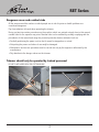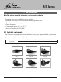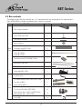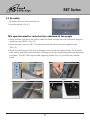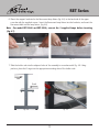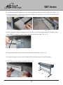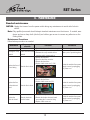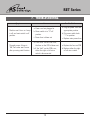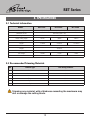
1
OWNER'S MANUAL
RET Series
Read all instructions carefully before use.
For any Customer Support needs please choose the
Customer Support tab on www.royalsovereign.com
Royal Sovereign International Inc.
www.royalsovereign.com
RET Series
TABLE OF CONTENTS
TOPIC∙∙∙∙∙∙∙∙∙∙∙∙∙∙∙∙∙∙∙∙∙∙∙∙∙∙∙∙∙∙∙∙∙∙∙∙∙∙∙∙∙∙∙∙∙∙∙∙∙∙∙∙∙∙∙∙∙∙∙∙∙∙∙∙∙∙∙∙∙ PAGE
1. INTRODUCTION∙∙∙∙∙∙∙∙∙∙∙∙∙∙∙∙∙∙∙∙∙∙∙∙∙∙∙∙∙∙∙∙∙∙∙∙∙∙∙∙∙∙∙∙∙∙∙∙∙∙∙∙∙∙∙∙∙∙∙∙∙∙∙∙∙∙∙∙∙∙∙∙∙∙∙∙∙∙∙∙∙∙∙∙∙∙∙∙∙∙∙∙∙∙∙∙∙∙∙∙∙ 3
2. SAFETY PRECAUTIONS∙∙∙∙∙∙∙∙∙∙∙∙∙∙∙∙∙∙∙∙∙∙∙∙∙∙∙∙∙∙∙∙∙∙∙∙∙∙∙∙∙∙∙∙∙∙∙∙∙∙∙∙∙∙∙∙∙∙∙∙∙∙∙∙∙∙∙∙∙∙∙∙∙∙∙∙∙∙∙∙∙∙∙∙∙∙∙∙∙∙∙ 3
3. PRODUCT IDENTIFICATION ∙∙∙∙∙∙∙∙∙∙∙∙∙∙∙∙∙∙∙∙∙∙∙∙∙∙∙∙∙∙∙∙∙∙∙∙∙∙∙∙∙∙∙∙∙∙∙∙∙∙∙∙∙∙∙∙∙∙∙∙∙∙∙∙∙∙∙∙∙∙∙∙∙∙∙∙∙∙∙∙∙∙∙∙ 5
4. INSTALLATION∙∙∙∙∙∙∙∙∙∙∙∙∙∙∙∙∙∙∙∙∙∙∙∙∙∙∙∙∙∙∙∙∙∙∙∙∙∙∙∙∙∙∙∙∙∙∙∙∙∙∙∙∙∙∙∙∙∙∙∙∙∙∙∙∙∙∙∙∙∙∙∙∙∙∙∙∙∙∙∙∙∙∙∙∙∙∙∙∙∙∙∙∙∙∙∙∙∙∙∙∙∙∙ 6
4.1 Electrical requirements∙∙∙∙∙∙∙∙∙∙∙∙∙∙∙∙∙∙∙∙∙∙∙∙∙∙∙∙∙∙∙∙∙∙∙∙∙∙∙∙∙∙∙∙∙∙∙∙∙∙∙∙∙∙∙∙∙∙∙∙∙∙∙∙∙∙∙∙∙∙∙∙∙∙∙∙∙∙∙∙∙∙∙∙∙6
4.2 Box contents∙∙∙∙∙∙∙∙∙∙∙∙∙∙∙∙∙∙∙∙∙∙∙∙∙∙∙∙∙∙∙∙∙∙∙∙∙∙∙∙∙∙∙∙∙∙∙∙∙∙∙∙∙∙∙∙∙∙∙∙∙∙∙∙∙∙∙∙∙∙∙∙∙∙∙∙∙∙∙∙∙∙∙∙∙∙∙∙∙∙∙∙∙∙∙∙∙∙∙∙7
4.3 Assembly∙∙∙∙∙∙∙∙∙∙∙∙∙∙∙∙∙∙∙∙∙∙∙∙∙∙∙∙∙∙∙∙∙∙∙∙∙∙∙∙∙∙∙∙∙∙∙∙∙∙∙∙∙∙∙∙∙∙∙∙∙∙∙∙∙∙∙∙∙∙∙∙∙∙∙∙∙∙∙∙∙∙∙∙∙∙∙∙∙∙∙∙∙∙∙∙∙∙∙∙∙∙∙∙∙8
5. OPERATION∙∙∙∙∙∙∙∙∙∙∙∙∙∙∙∙∙∙∙∙∙∙∙∙∙∙∙∙∙∙∙∙∙∙∙∙∙∙∙∙∙∙∙∙∙∙∙∙∙∙∙∙∙∙∙∙∙∙∙∙∙∙∙∙∙∙∙∙∙∙∙∙∙∙∙∙∙∙∙∙∙∙∙∙∙∙∙∙∙∙∙∙∙∙∙∙∙∙∙∙∙∙∙∙∙∙11
6. MAINTENANCE∙∙∙∙∙∙∙∙∙∙∙∙∙∙∙∙∙∙∙∙∙∙∙∙∙∙∙∙∙∙∙∙∙∙∙∙∙∙∙∙∙∙∙∙∙∙∙∙∙∙∙∙∙∙∙∙∙∙∙∙∙∙∙∙∙∙∙∙∙∙∙∙∙∙∙∙∙∙∙∙∙∙∙∙∙∙∙∙∙∙∙∙∙∙∙∙∙∙∙∙ 12
7. TROUBLESHOOTING∙∙∙∙∙∙∙∙∙∙∙∙∙∙∙∙∙∙∙∙∙∙∙∙∙∙∙∙∙∙∙∙∙∙∙∙∙∙∙∙∙∙∙∙∙∙∙∙∙∙∙∙∙∙∙∙∙∙∙∙∙∙∙∙∙∙∙∙∙∙∙∙∙∙∙∙∙∙∙∙∙∙∙∙∙∙∙∙∙∙∙∙∙ 13
8. SPECIFICATIONS∙∙∙∙∙∙∙∙∙∙∙∙∙∙∙∙∙∙∙∙∙∙∙∙∙∙∙∙∙∙∙∙∙∙∙∙∙∙∙∙∙∙∙∙∙∙∙∙∙∙∙∙∙∙∙∙∙∙∙∙∙∙∙∙∙∙∙∙∙∙∙∙∙∙∙∙∙∙∙∙∙∙∙∙∙∙∙∙∙∙∙∙∙∙∙∙∙∙ 14
9. WARRANTY∙∙∙∙∙∙∙∙∙∙∙∙∙∙∙∙∙∙∙∙∙∙∙∙∙∙∙∙∙∙∙∙∙∙∙∙∙∙∙∙∙∙∙∙∙∙∙∙∙∙∙∙∙∙∙∙∙∙∙∙∙∙∙∙∙∙∙∙∙∙∙∙∙∙∙∙∙∙∙∙∙∙∙∙∙∙∙∙∙∙∙∙∙∙∙∙∙∙∙∙∙∙∙∙∙∙ 15
2
RET Series
1. INTRODUCTION
Thank you for choosing a Royal Sovereign trimmer. It has been designed and manufactured to provide
years of continuous service. For complete operating and maintenance information please read this
manual thoroughly. Upon receipt of your trimmer, please inspect the box, the machine and all other
contents for shipping damage. Damage should be brought to the immediate attention of the delivering
carrier (See page 7 for list of shipment elements).
2. SAFETY PRECAUTIONS
Failure to comply with any of the following safety procedures could result in serious injury. Please read
all instructions carefully and keep for future reference. Royal Sovereign International Inc. cannot be held
responsible for any damages to people, animals or objects due to noncompliance with the safety norms
and recommendations of these documents.
1. Only a licensed electrician should install wiring and outlet for the trimmer.
2. Ensure the unit is plugged into a properly grounded outlet with the correct voltage.
3. Keep hands away from cutting blade when in operation.
4. Keep flammable and wet objects away from the machine.
5. Place machine on a level surface.
6. Avoid excessive sunlight, humidity and extreme temperatures.
7. Ensure the unit is turned off and unplugged from the outlet prior to moving and/or repairing.
8. Keep out of reach of children.
9. Only Royal Sovereign authorized maintenance and service technicians should make repairs.
10. Do not attempt to trim items that exceed total recommended material thickness for the unit.
11. When cleaning the machine, don't use flammable sprays or materials.
12. Do not touch the blade when in use or place foreign objects inside the machine.
13. Tampering with the protections (rear cover, safety cover, protector plate) and safety devices
is dangerous for the people using the machine and for those exposed to it. Royal Sovereign
International Inc. cannot be held responsible for any damages to people, animals or objects due to
tampering with the protections.
14. Pay attention to the danger notices on the trimmer.
3
RET Series
Dangerous areas and residual risks
All the areas around the machine in which people are at risk of injuries or health problems are
considered dangerous.
Pay close attention to hands when operating the trimmer.
During certain intervention procedures on the machine, which are pointed out each time in this manual,
residual risks for the operator may arise. Residual risks can be avoided by carefully complying with the
procedures of this manual and using the personal protection devices indicated. such as:
• Carefully positioning the power cord so that it cannot be stepped on or ruined.
• Not putting the power cord where it can easily be damaged.
• Maintenance and service operations must be carried out only by the engineers authorized by the
manufacturer.
• Pay attention to the danger notices on the trimmer.
Trimmer should only be operated by trained personnel
DO NOT PLACE HANDS NEAR THE CUTTING BLADE !
4
RET Series
3. PRODUCT IDENTIFICATION
12
1
11
10
2
9
3
4
8
5
7
6
NO
PART NAME
1
2
3
4
5
6
7
8
9
10
11
12
Left Side Cover
Power Switch
Feed Table Front
Fabric Holder Rod
Protection Plate
Foot Pedal
Floor Stand
Waste Catcher
Right Side Cover
Rear Cover
Activation Bar
Safety Cover
5
RET Series
4. INSTALLATION
Note: The trimmer should be installed by a trained service technician
The trimmer needs to be assembled by a trained installer.
The trimmer should only be used in an area with the following characteristics:
• Protection from atmospheric agents
• Proper illumination
• Temperatures between 64° F and 95° F
• Amount of humidity from 30% to 80%
4.1 Electrical requirements
Royal Sovereign recommends that a licensed electrician ensures proper power installation to your trimmer
in accordance with electrical codes in your area.
The trimmer should have a dedicated power line.
100V(50/60Hz),110~120V(60Hz),220V(60Hz),220~240V(50Hz)
Single phase
Power Supply
120V UL
230V UL
240V UK
220V EU
240V AU
220V KR
6
RET Series
4.2 Box contents
Thoroughly inspect the parts and the unit. It is imperative that any missing parts are reported and a
claim is filed with the reseller immediately upon receipt of shipment.
Part Name
Main
Box
Tool
Box
Quantity
Main Trimmer Assembly
1
Floor Stand Side Frame
2
Floor Stand Cross Bar
2
Owner's Manual
1
Protection Plate (RET-1500/RET-2000)
1
Protection Plate (RET-2500)
Lamp (RET-1500)
2
1
Lamp (RET-2000)
2
Lamp (RET-2500)
2
Connection Socket (RET-2000/RET-2500)
1
Wastecatcher Square Bars
2
Fabric Holder Bars
4
Braket table(RET-2500)
2
L-wrench (4/6)
1/1
5/16 Hexa head bolt (M8*55mm / M8*15mm)
10 / 4
Star washer (Ø8.2)
6
Spring washer (Ø8.2)
5/32 screw (M4*8mm) (RET-1500/RET-2000)
8
4
5/32 screw (M4*8mm) (RET-2500)
10
Spring washer (Ø4.1) (RET-1500/RET-2000)
4
Spring washer (Ø4.1) (RET-2500)
10
E-ring (Ø8)
8
7
Picture
RET Series
4.3 Assembly
1. Open the box carton and remove all parts.
2. Open the tool-box. (Fig. 4-1)
Fig. 4-1
This operation must be carried out by a minimum of two people
3. Attach the lower cross bar to the left floor stand side frame and right floor stand side frame using the
supplied screws (M8x55). (Fig. 4-2)
4. Attach the upper cross bar (Fig. 4-3) to the floor stand side frames using the supplied screws
(M8×15).
5. Attach the protection plate (Fig. 4-4) to the upper cross bar with the supplied screws. The protection
plate must be assembled on the front part of the upper cross bar, always keeping the table adjustment
pin upward. (For RET-2500 only, the table supporting shelves (Fig. 4-5) must face the protection
panel)
Fig. 4-2
Fig. 4-3
Fig. 4-4
Fig. 4-5
8
RET Series
6. Mount the support brackets for the fluorescent lamp fixture (fig. 4.6) to the back side of the upper
cross bar with the supplied screws. Insert the fluorescent lamp fixture into the brackets, and insert the
fluorescent bulb into the lamp fixture. (fig. 4.6)
Note : For model RET-2000 and RET-2500, connect the 2 supplied lamps before inserting
(fig.4.7)
Fig. 4-6
Fig. 4-7
7. Slide the holder rods into the adjacent holes of the assembly in accordance with Fig. 4-8. Using
pinchers, place the E-rings into the appropriate mounting slots of the holder rods.
rear
front
Fig. 4-8
Fig. 4-9
9
RET Series
8. Screw the wastecatcher square bars into the previously inserted wastecatcher holder rods, (Fig. 4-10)
putting the supplied screws through the largest drilling in the square bar, so that the head of the screw
sits flush within the bar itself. (Fig. 4-11)
Fig. 4-10
Fig. 4-11
9. Position the main trimmer assembly on top of the floor stand. And properly align the bolt holes. Use
bolts (M8x55) to attach the main trimmer assembly to the floor stand. (Fig. 4-12)
Fig. 4-12
10. Plug the lamp cable into the socket on the fluorescent lamp fixture. (Fig. 4-13)
11. Connect the power cord in to the AC outlet and turn the Power switch to the ON position.
12. The Trimmer is now ready for Operation. (Fig. 4-14)
Fig. 4-13
Fig. 4-14
10
RET Series
5. OPERATION
The trimmer must only be used by trained and qualified personnel. The trimmer must be
used only for trimming material for which it has been designed. For recommended
maximum cutting thickness see page 16.
1. The trimmer should be positioned on a level surface in an area with adequate lighting and enough
work space for feeding materials. Connect the power cord to the AC outlet and turn the Power switch
to the ON position. The machine should be operated from the front of the machine only.
2. To begin trimming material, position the material to be trimmed on the front feeding table (Fig. 5-1)
and measure the cut by using the scales present at either side of the feed table or by the guideline.
Do not lean against or put any object on the feeding table during trimming.
3. When the material is properly positioned press the activation bar (Fig. 5-2) anywhere along the length
of the trimmer to activate the cutting blade or step on the foot pedal (Fig. 5-3) to activate the cutting
blade. The material can now be removed or repositioned for another cut.
Fig. 5-1
Fig. 5-2
11
Fig. 5-3
RET Series
6. MAINTENANCE
Standard maintenance
CAUTION: Unplug the trimmer from the power outlet during any maintenance to avoid risk of electric
shocks.
Note: Only qualified personnel should attempt standard maintenance on the trimmer. If needed, wear
gloves and use a damp cloth (alcohol) and rubber gum eraser to remove any adhesive on the
cutting blade.
Maintenance Procedures
Follow below procedures as needed.
Maintenance
General dusting
Frequency of
execution
At user's discretion
Procedure
Precautions
• Clean the entire machine with a damp cloth Do not use aggressive products
• Remove the safety-cover
Cleaning the scrap If there is a lot of scrap
• Eliminate the scrap material with an
Wear a pair of protection gloves
material
material
aspirator and/or compressed air
• Remove the left panel
• Open the take-fuse connector
• Remove the burnt fuse
• Replace it with a new one (3.15A)
Isolate the machine from power
Replace the fuse of
When the fuse is burnt
supply sourses by unplugging
general wiring
the power cord
• Remove the left panel
• Remove the burnt fuse
• Replace it with a new one (2A)
Replace the fuse
on the electronic
board
When the fuse is burnt
Replace the
electronic board
When the electronic
board is broken
• Remove the left panel
• Remove the broken electronic board
unscrewing the 3 screws for fixing
• Replace it with a new one
12
Isolate the machine from power
supply sourses by unplugging
the power cord
Isolate the machine from power
supply sourses by unplugging
the power cord
RET Series
7. TROUBLESHOOTING
Symptoms
Cause
Possible Solution
Machine won't turn on. Lamp
is off, and main switch is off
position
a. Power cord not plugged in
b. Power switch is in “0” off
position
c. P ower fuse is blown out
a. Plug the power cord into
appropriate position
b. Put power switch back
“1” on position
c. Replace main power fuse
Thought power & lamp is
'ON', but cutter won't move
after pressing switch button
a. If the 'led3' on the PCB is off,
the fuse on the PCB is blown out
b. If the 'led3' on the PCB is on,
either the right or left micro
switch is disconnected
a. Replace the fuse on PCB
b. Replace either the right
or left micro switch
13
RET Series
8. SPECIFICATIONS
9.1 Technical information
MODEL
RET-1500
RET-2000
RET-2500
Power supply
100V(50/60Hz), 110~120V(60Hz), 220V(60Hz), 220~240V(50Hz)
Absorbed current
max 0.8A -(max 1.5A)
Max cutting thickness
30mil
Usable cutting length
59inch
Cutting speed
78inch
98inch
6.6ft/sec
Length
77.6inch
99.2inch
Width
19.9inch
Height
40.2inch
Working table height
116.9inch
34.3inch
Unit weight
106lbs
Accessories
131lbs
155lbs
Roll Feeder
9.2 Recommended Trimming Materials
NO
Material Type
Max.cutting thickness
1
Canvas
20mil
2
Laminate
15mil
3
Lexan
10mil
4
Paper
30mil
5
Styrene
30mil
6
Vinyl
20mil
Trimming any material with a thickness exceeding the maximum may
dull or damage the cutting blade.
14
RET Series
9. WARRANTY
Royal Sovereign International warrants the equipment sold is free from defects in material and workmanship
for a period of One (1) year for Parts and Labor from the date of installation, excluding cutting blades which
are warranted for Six (6) months. This warranty is valid only to the original purchaser. This warranty is the
only warranty made by Royal Sovereign International and cannot be modified or amended. Royal Sovereign’s
sole and exclusive liability and the customer’s sole and exclusive remedy under this warranty shall be, at
Royal Sovereign’s option, to repair or replace any such defective part or product. These remedies are
only available if Royal Sovereign’s examination of the product discloses to Royal Sovereign’s satisfaction
that such defects actually exist and were not caused by misuse, neglect, attempt to repair, unauthorized
alternation or modification, incorrect line voltage, fire, accident, flood or other hazard.
All warranty claims must be filed through Royal Sovereign or the authorized Royal Sovereign dealer or
reseller through which the equipment was originally purchased. Model, serial number and date of delivery
are required for all claims.
The warranty made herein is in lieu of all other warranties, expressed or implied, including any warranty or
merchantability or fitness for a particular purpose. Royal Sovereign will not be liable for personal damage or
personal injury (unless primarily caused by its negligence), loss of profit, or other incidental or consequential
damages arising out of the use or inability to use this equipment. This warranty is only valid in the
continental United States.
LIMITED WARRANTY
This warranty specifically does not cover damage to cutting blade caused by attempted cutting of
materials and/or thicknesses of materials other than those specified for use in the user manual, or failure
caused by adhesives, or damage caused by lifting, tilting or improper use of the machine. Warranty repair
or replacement by Royal Sovereign or its authorized Reseller(s) does not extend the warranty beyond
the initial one year period from the date of installation. Unauthorized customer alterations will void this
warranty.
ROYAL SOVEREIGN INTERNATIONAL, INC.
RS CANADA INC.
2 Volvo Drive Rockleigh, NJ 07647 USA
1025 Westport Crescent, Mississauga On L5T 1E8 CANADA
TEL : +1) 800-397-1025 FAX : +1) 201-750-1022
TEL : +1) 905-461-1095 FAX : +1) 905-461-1096
TF # : +1) 866-961-6673
RS EUROPE LIMITED.
RS INTERNATIONAL AUSTRALIA PTY. LTD.
66 Salisbury Road, Worcester Park, Surrey KT4 7DE UK
30 Prime Drive, Seven Hills, NSW 2147, AUSTRALIA
TEL.: +44) 2082243633
TEL : +61) 2-9674-2127 FAX : +61) 2-9674-2027
www.royalsovereign.com
15