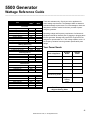
1
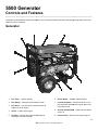
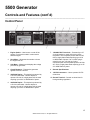
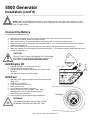
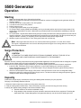
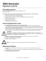
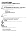
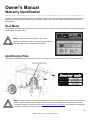
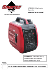
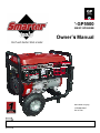
ST-GP5500
ST-GP5500/ST-GP5500E/ST-GP5500EB
Owner’s Manual
WARNING! To Reduce Risk of Injury,
User Must Read and Understand
Owner’s Manual Prior to Use.
Use
NOTE: Retain Original Sales Receipt as Proof of Purchase!
ST-GP5500
ST-GP5500/ST-GP5500E/ST-GP5500EB
5500W Generator
Table of Contents
Introduction .............................................................. 03
Safety Guidelines – Definitions .............................. 04
General Precautions ................................................ 05
Carbon Monoxide .......................................... 05
Gasoline and Oil ............................................ 05
Hot Components ........................................... 06
Power Output ................................................ 06
Work Area ..................................................... 06
Electrical Safety ............................................ 07
Personal Safety ............................................. 07
General Use and Care .................................. 08
Servicing........................................................ 08
Installation ..................................................... 09
Mechanical .................................................... 09
Chemicals...................................................... 10
Noise ............................................................. 10
Extension Cords ............................................ 10
Controls and Features ............................................. 11
Generator ...................................................... 11
Control Panel ................................................ 12
Installation ................................................................ 13
General Location ........................................... 13
Wheel and Handle Kit Installation ................. 14
Support and Mounting ................................... 14
Grounding...................................................... 14
Connect the Battery ...................................... 15
Add Engine Oil .............................................. 15
Add Fuel ........................................................ 15
Operation .................................................................. 16
Starting .......................................................... 16
Surge Protection ........................................... 16
Capacity ........................................................ 16
Power Management ...................................... 17
Connecting Electrical Loads.......................... 17
Stopping the Engine ...................................... 17
Wattage Reference Guide ........................................ 18
Your Power Needs ......................................... 18
Inspection, Cleaning, and Maintenance ................. 19
Changing Oil .................................................. 19
Spark Plug ..................................................... 20
Air Filter .......................................................... 20
Spark Arrester (optional) ................................ 20
Cleaning ......................................................... 20
Maintenance Schedule .................................. 20
Storage .......................................................... 21
Transporting ................................................... 21
Specifications............................................................ 22
Parts Lists .................................................................. 23
Crankcase Assembly ..................................... 23
Crankshaft Assembly ..................................... 23
Crankshaft Assembly and Piston ................... 24
Cylinder Head Assembly ............................... 24
Camshaft Assembly ....................................... 25
Centrifugal Timing Implement Assembly ....... 26
Inflame Assembly .......................................... 26
Starter Assembly............................................ 27
Engine Sprocket Cover .................................. 27
Carburetor Assembly ..................................... 27
Valve Cover Assembly................................... 28
Choke Assembly ............................................ 28
Generator Assembly ...................................... 29
Gas Tank ....................................................... 29
Control Panel Assembly ................................ 30
Muffler ............................................................ 30
Frame Assembly ............................................ 31
Motor Shield ................................................... 31
Troubleshooting........................................................ 32
Warranty Identification ............................................. 33
Limited Warranty....................................................... 34
WARNING!
READ AND UNDERSTAND ALL SAFETY PRECAUTIONS IN THIS MANUAL BEFORE OPERATING.
FAILURE TO COMPLY WITH INSTRUCTIONS IN THIS MANUAL COULD RESULT IN PERSONAL
INJURY, PROPERTY DAMAGE, AND/ OR VOIDING OF YOUR WARRANTY. SMARTER TOOLS WILL
NOT BE LIABLE FOR ANY DAMAGE BECAUSE OF FAILURE TO FOLLOW THESE INSTRUCTIONS.
2
©2009 Smarter Tools, Inc. All Rights Reserved
5500W Generator
Introduction
_________________________________________________________________________________________________
Congratulations on your purchase of a Smarter Tools
generator. Smarter Tools designs and builds generators
to strict specifications. With proper use and maintenance,
this generator will bring years of satisfying service.
Portable Power Generator
This unit is an electric start, gasoline engine driven,
alternating current (AC) generator. It is designed to
supply electrical power for lighting, appliances, tools
and similar equipment.
This Booklet
Every effort has been made to ensure the accuracy
and completeness of the information in this manual.
We reserve the right to change, alter and/or improve
the product and this document at any time without prior
notice. For the most up to date information regarding
your Smarter Tools product please visit us at
www.usesmartertools.com
Record the model and serial numbers as well as date and place of purchase for future reference.
Have this information available when ordering parts and when making technical or warranty inquiries.
Smarter Tools Customer Service
1-804-798-8588
Model Number
GP5500 (E, EB)
Serial Number
Date of Purchase
Purchase Location
3
©2009 Smarter Tools, Inc. All Rights Reserved
Owner’s Manual
Safety Guidelines - Definitions
_________________________________________________________________________________________________
This manual contains important information that you need to know and understand in order to assure YOUR SAFETY and
PROPER OPERATION OF EQUIPMENT. The following symbols help you recognize this information. Please read the
manual and pay attention to these sections.
Save These Important Safety Instructions!
Read and understand all of these safety instructions. Be sure to retain them for future use.
WARNING!
WARNINGS INDICATE A CERTAINTY OR STRONG POSSIBILITY OF PERSONAL INJURY OR
DEATH IF INSTRUCTIONS ARE NOT FOLLOWED.
CAUTION:
CAUTIONS INDICATE A POSSIBILITY OF EQUIPMENT DAMAGE IF INSTRUCTIONS ARE NOT
FOLLOWED PROPERLY.
Note: Notes give helpful information.
WARNING!
IMPROPER OPERATION OR MAINTENANCE OF THIS PRODUCT COULD RESULT IN SERIOUS
INJURY AND PROPERTY DAMAGE. READ AND UNDERSTAND ALL WARNINGS AND OPERATING
INSTRUCTIONS BEFORE USING THIS EQUIPMENT. BASIC SAFETY PRECAUTIONS SHOULD
ALWAYS BE FOLLOWED TO REDUCE THE RISK OF PERSONAL INJURY.
Save These Important Safety Instructions!
Read and understand all of these safety instructions. Be sure to retain them for future use.
4
©2009 Smarter Tools, Inc. All Rights Reserved
Owner’s Manual
General Safety Precautions
_________________________________________________________________________________________________
WARNING!
FAILURE TO FOLLOW THESE INSTRUCTIONS CAN RESULT IN SEVERE INJURY OR DEATH.
CAUTION:
FAILURE TO FOLLOW THESE INSTRUCTIONS CAN ALSO RESULT IN DAMAGE TO THE EQUIPMENT
AND/OR THE ITEM YOU ARE WORKING ON OR WITH.
Carbon Monoxide
•
•
•
•
•
•
•
Carbon Monoxide is an odorless and colorless gas. Breathing exhaust that contains this poisonous gas can cause
unconsciousness and may lead to death.
The engine exhaust from this product contains chemicals recognized by the state of California to cause cancer,
birth defects, or other reproductive harm.
When this tool is running, ensure that the area is well ventilated. Never run the engine in an enclosed area. Run
the engine in an open area or with an exhaust evacuation system in an enclosed area.
NEVER use a generator inside homes, garages, crawlspaces, or other partially enclosed areas. Deadly levels of
carbon monoxide can build up in these areas. Using a fan or opening windows and doors does NOT supply
enough fresh air.
ONLY use a generator outdoors and far away from open windows, doors, and vents. These openings can pull in
generator exhaust.
Even when you use a generator correctly, CO may leak into the home. ALWAYS use a battery-powered or
battery-backup CO alarm in the home.
If you start to feel sick, dizzy, or weak after the generator has been running, move to fresh air RIGHT AWAY. See
a doctor. You could have carbon monoxide poisoning.
WARNING!
THE EXHAUST CONTAINS POISONOUS CARBON MONOXIDE GAS THAT CAN CAUSE LOSS OF
CONSCIOUSNESS AND MAY LEAD TO DEATH.
Gasoline and Oil
This product requires oil and fuel. THE ENGINE WILL NOT START WITHOUT OIL. Work in well ventilated area. Keep
cigarettes, flames or sparks away from the work area or where gasoline is stored.
WARNING!
GASOLINE IS EXTREMELY FLAMMABLE AND IS EXPLOSIVE UNDER CERTAIN CONDITIONS. KEEP
OUT OF REACH OF CHILDREN.
5
©2009 Smarter Tools, Inc. All Rights Reserved
Owner’s Manual
General Safety Precautions (cont’d)
_________________________________________________________________________________________________
Gasoline and Oil (cont’d)
•
•
•
•
•
•
•
•
•
Gasoline fuel and fumes are flammable and potentially explosive. Use proper fuel storage and handling
procedures. Always have multiple ABC class fire extinguishers nearby.
Keep the generator and surrounding area clean at all times. Keep the generator at least 5 feet away from
buildings and other equipment during operation.
Fuel or oil spills must be cleaned up immediately. Dispose of fluids and cleaning materials as per any local, state,
or federal codes and regulations. Store oily rags in a covered metal container.
Never store fuel or other flammable materials near the generator.
Do not smoke, or allow sparks, flames or other sources of ignition around the engine and fuel tank. Fuel vapors
are explosive.
Keep grounded conductive objects, such as tools, away from exposed, live electrical parts and connections to
avoid sparking or arcing. These events could ignite fumes or vapors.
Do not refill the fuel tank while the engine is running or while the engine is still hot. Do not operate the generator
with known leaks in the fuel system.
Excessive buildup of unburned fuel gases in the exhaust system can create a potentially explosive condition. This
buildup can occur after repeated failed start attempts, valve testing, or hot engine shutdown. If this occurs, open
exhaust system drain plugs, if equipped, and allow the gases to dissipate before attempting to restart the generator.
Use only engine manufacturer recommended fuel and oil.
Hot Components
WARNING!
HOT EXHAUST CAN BURN YOU. ENGINE AND EXHAUST SYSTEM PARTS BECOME VERY HOT AND
REMAIN HOT FOR SOME TIME AFTER THE ENGINE IS RUN. WEAR INSULATED GLOVES OR WAIT
UNTIL THE ENGINE AND EXHAUST SYSTEM HAVE COOLED BEFORE HANDLING THESE PARTS.
Power Output
This generator is not designed to power sensitive electronic equipment (including computers and medical devices) without
the addition of an approved line conditioner, which is sold separately.
CAUTION:
ATTEMPTING TO POWER SENSITIVE ELECTRONIC EQUIPMENT WITHOUT THE USE OF AN
APPROVED LINE CONDITIONER MAY CAUSE DAMAGE TO THE EQUIPMENT.
Work Area
•
•
•
Keep your work area clean and well lit. Cluttered benches and dark areas invite accidents.
Do not operate power tools in explosive atmospheres, such as in the presence of flammable liquids, gases, or
dust. Generators create sparks which may ignite the dust or fumes.
Keep bystanders, children, and visitors away while operating a generator. Provide barriers or shields as needed.
6
©2009 Smarter Tools, Inc. All Rights Reserved
Owner’s Manual
General Safety Precautions (cont’d)
_________________________________________________________________________________________________
Electrical Safety
•
•
•
•
•
•
•
•
•
•
•
•
•
•
•
•
Keep all electrical equipment clean and dry. Replace any wiring where the insulation is cracked, cut eroded part
or otherwise degraded. Replace terminals that are worn, discolored, or corroded. Keep terminals clean and tight.
Insulate all connections and disconnected wires.
Do not abuse the power cord. Keep power cords away from heat, oil, sharp edges, or moving parts. Replace
damaged power cords immediately. Damaged power cords increase the risk of electric shock.
Do not operate the generator with wet hands. Do not expose generator to rain, snow or wet conditions. Water will
increase the risk of electric shock. The generator is a potential source of electrical shock if not kept dry.
Do not attempt to connect or disconnect load connections while standing in water, or on wet or soggy ground.
Do not touch electrically energized parts of the generator and interconnecting cables or conductors with any part
of the body, or with any non-insulated conductive object.
Avoid body contact with grounded surfaces such as pipes, radiators, ranges, and refrigerators. There is an
increased risk of electric shock if your body is grounded.
When operating a power tool outside, use an outdoor extension cord marked “W-A” or “W”. These extension
cords are rated for outdoor use, and reduce the risk of electric shock.
Grounded tools must be plugged into an outlet properly installed and grounded in accordance with all codes and
ordinances. Never remove the grounding prong or modify the plug in any way. Do not use any adapter plugs.
Double insulated tools are equipped with a polarized plug where one blade is wider than the other. This plug fits in
a polarized outlet only one way. If the plug does not fit fully in the outlet, reverse the plug. If it still does not fit,
contact a qualified electrician to install a polarized outlet. Do not change the plug in any way. Double insulation
eliminates the need for the three-wire grounded power cord and grounded power supply system.
Before servicing equipment powered by the generator, disconnect the equipment from its power input.
The generator must be earth-grounded for fixed installations in accordance with all relevant electrical codes and
standards before operation.
Grounding provides a low-resistance path to carry electricity away from the user in the event of an electrical
malfunction.
All connections and conduits from the generator to the load must only be installed by trained and licensed
electricians and in compliance with all relevant local, state, and federal electrical codes and standards, and other
regulations where applicable.
Connect the generator only to a load or electrical system (110/120 volt) that is compatible with the electrical
characteristics and rated capacities of the generator.
NEVER try to power building or home wiring by plugging the generator into a wall outlet, a practice known as
“backfeeding.” This is extremely dangerous and presents an electrocution risk to utility workers and neighbors
served by the same utility transformer. It also bypasses some of the built-in household circuit protection devices.
Personal Safety
CAUTION:
DO NOT SIT, STAND, OR PLACE OBJECTS ON TOP OF THE GENERATORS FUEL TANK.
REGARDLESS OF WHETHER IT IS RUNNING OR NOT.
•
•
•
•
Stay alert. Watch what you are doing, and use common sense when operating a generator. Do not use generator
while tired or under the influence of drugs, alcohol, or medication. A moment of inattention while operating
generators may result in serious personal injury.
Make note of the location of the engine power switch should you need to turn off the generator quickly.
Dress properly. Contain long hair, clothing, jewelry, and gloves as they can be caught in moving parts.
Avoid accidental starting. Make sure the power switch is in its “OFF” position, and disconnect the spark plug wire
when not in use.
7
©2009 Smarter Tools, Inc. All Rights Reserved
5500 Generator
General Safety Precautions (cont’d)
_________________________________________________________________________________________________
Personal Safety (cont’d)
•
•
•
Remove adjusting keys or wrenches before turning the generator on. A wrench or a key that is left attached to a
rotating part of the generator may result in personal injury.
Do not overreach. Keep proper footing and balance at all times.
Use safety equipment. Always wear eye protection. Wear ANSI approved safety impact eye goggles. Dust mask,
non-skid safety shoes, safety gloves, hard hat, or hearing protection must be used for appropriate conditions.
•
Do not use the generator if the power switch does not turn it on or off. Any generator
that cannot be controlled with the power switch is dangerous and must be replaced.
•
Do not force the generator. Use the correct generator for your application. The correct
generator will do the job better and safer at the rate for which it is designed.
•
The generator weighs 167 lbs. Two or more people should assist when moving or lifting this product. Never lift the
Generator using the engine or alternator lifting lugs. Connect lifting equipment to the Frame of the generator.
Generator Use and Care
•
•
•
•
•
Make sure the power switch is in its “OFF” position and disconnect the spark plug wire before making any
adjustment, changing accessories, or storing the generator. Such preventive safety measures reduce the risk of
starting the generator accidentally.
Store idle generators out of reach of children and other untrained persons. Generators are dangerous in the
hands of untrained users.
Maintain generators with care. Do not use a damaged generator. Tag damaged generators “Do not use” until
repaired.
Check for misalignment or binding of moving parts, breakage of parts, and any other condition that may affect the
generator’s operation. If damaged, have the generator serviced before using. Many accidents are caused by
poorly maintained generators.
Use only accessories that are recommended by the manufacturer for your model. Accessories that may be
suitable for one generator may become hazardous when used on another generator.
Servicing
•
•
•
Maintain labels and name plates on the generator and engine. These carry important information. If unreadable or
missing, contact Smarter Tools immediately for a replacement.
Generator service must be performed only by qualified repair personnel. Service or maintenance performed by
unqualified personnel could result in a risk of injury.
When servicing a generator, use only identical replacement parts. Follow all appropriate instructions in this
manual. Use of unauthorized parts or failure to follow maintenance instructions may create a risk of electric shock
or injury.
WARNING!
PEOPLE WITH PACEMAKERS SHOULD CONSULT THEIR PHYSICIAN(S) BEFORE USING THIS
PRODUCT. ELECTROMAGNETIC FIELDS IN CLOSE PROXIMITY TO A HEART PACEMAKER COULD
CAUSE INTERFERENCE TO OR FAILURE OF THE PACEMAKER.
8
©2009 Smarter Tools, Inc. All Rights Reserved
Owner’s Manual
General Safety Precautions (cont’d)
_________________________________________________________________________________________________
Installation
•
•
•
•
•
•
•
•
•
•
•
Ensure installation meets all applicable safety, and local and national electrical codes. Have installation performed
by a qualified, licensed electrician and building contractor.
All electrical work, including the earth-ground connection, should be completed by a licensed electrician.
Any separate fuel storage or generator supply facility must be built or installed in full compliance with all relevant
local, state, and federal regulations.
It is recommended to use the generator only in well ventilated outdoor areas. A running gasoline engine will
generate carbon monoxide, a colorless, odorless gas that, if inhaled, can cause serious injury or death. If the
generator is installed indoors, exhaust fumes must be piped out of the building using leak-free, heat resistant
piping. Pipes and silencer should not use any flammable materials, nor should they be installed near the same.
Generator exhaust fumes must be within legal limits and installation must always meet local building codes.
If the generator is installed outdoors, it must be weatherproofed and should be soundproofed. It should not be run
outdoors without protection of the generator and wiring conduit.
Two or more people should assist when moving or lifting this product. Never lift the Generator using the engine or
alternator lifting lugs. Connect lifting equipment to the Frame of the generator.
Before lifting the generator, ensure the lift rigging and supporting structure are in good condition, and are rated to
lift such a load.
Keep all personnel away from the suspended generator during relocating.
The supporting floor/ground surface should be level, and strong enough to safely hold the weight of the generator.
If the floor/grounded surface is not level, strong cross members should be placed under the full length of the
generator frame at its low side.
For trailer installation, the generator should be mounted on the center point of the trailer, over the wheels. The
trailer must be capable of supporting the weight of the generator and all contents (tools, etc.)
Install sound-and weather-proofing only when it is not raining or snowing to avoid trapping moisture within the
generator’s area.
Mechanical
•
•
•
•
•
•
•
•
•
Always make sure the power switch is in its “OFF” position. Disconnect the spark plug wire, and allow the engine
to completely cool before carrying out maintenance.
Check for damaged parts. Before using the generator, any part that appears damaged should be carefully
checked to determine that it will operate properly and perform its intended function. Check for alignment and
binding of moving parts, any broken parts or mounting fixtures, and any other condition that may affect proper
operation technician.
The generator is designed with guards for protection from moving parts. In any case, care must still be taken to
protect personnel and equipment from other mechanical hazards when working around the generator.
Do not operate the generator with safety guards removed. While the generator is running, do not attempt to reach
around the safety guard for maintenance or any other reason.
Keep hands, arms, long hair, loose clothing, and jewelry away from moving parts. Be aware that when engine
parts are moving fast they cannot be seen clearly.
Keep access doors on enclosures closed and locked when access is not required.
When working on or around the generator always wear protective clothing including ANSI approved safety gloves,
safety eye goggles, and safety hat.
Do not alter or adjust any part of the generator that is assembled and supplied by the manufacturer.
Always follow and complete scheduled engine and generator maintenance.
9
©2009 Smarter Tools, Inc. All Rights Reserved
Owner’s Manual
General Safety Precautions (cont’d)
_________________________________________________________________________________________________
Chemicals
•
•
Avoid contact with hot fuel, oil, exhaust fumes, and hot solid surfaces.
Avoid body contact with fuels, oils, and lubricants used in the generator. If swallowed, seek medical treatment
immediately. Do not induce vomiting if fuel is swallowed. For skin contact, immediately wash with soap and water.
For eye contact, immediately flush eyes with clean water and seek medical attention.
Noise
Prolonged exposure to noise levels above 85dBA is hazardous to hearing.
Always wear ANSI approved ear protection when operating or working around the Generator when it is running.
Extension Cords
If an extension cord (not included) is used, make sure to use only UL approved cords having the correct gauge and length
according to the following table:
Nameplate Amps
(@full load)
0-5
5.1-8
8.1-12
12.1-15
15-20
Cord Lengths
0”-50”
16
16
14
12
10
50”-100”
16
14
12
10
100”-150”
12
10
-
10
-
150”-200”
12
-
10
©2009 Smarter Tools, Inc. All Rights Reserved
5500 Generator
Controls and Features
_________________________________________________________________________________________________
Familiarize yourself with the location and function of the controls and features before operating your generator. Save this
manual for future reference.
Generator
1. Fuel Tank – 7 gallon capacity
6. Recoil Starter – Used to start the engine.
2. Fuel Gauge – Indicates amount of fuel in tank.
7. Low Oil Shutdown – Senses the level of oil in
the crankcase and shuts the engine down if the
level falls too low.
3. Fuel Valve – Turn this valve to the on position to
supply fuel to the engine
4. Choke – Used to start engine.
8. Oil Filler Cap/Dipstick – Used to check and fill
engine oil.
5. Air Filter – Protects the engine by filtering dust
and debris from the intake air.
9. Control Panel – See “Control Panel” page 12
11
©2009 Smarter Tools, Inc. All Rights Reserved
5500 Generator
Controls and Features (cont’d)
_________________________________________________________________________________________________
Control Panel
1. Engine Switch – Used to turn on and off the
engine. For electric models it is also used to
start the engine.
2. Hour Meter – Measures the number or hours
the engine has run.
3. Volt Meter – Measure and displays the voltage
produced by generator.
4. Circuit Breakers – Protects the generator
against electrical overload.
5. 120V 20A Duplex – This duplex is protected by
a 20 A circuit breaker. Use this duplex to
operate 120 volt AC, single phase, 60 Hz loads
requiring up to 20 A or 2400 Watts of power.
7. 120/240V 25A Twist-Lock – Protected by a 25
A circuit breaker on each 120 Volt leg of the
receptacle. This receptacle powers 240 Volt AC,
60 Hz, single phase loads requiring up to 20 A
or 4800 Watts of power. If an L14-30P plug is
wired for only one 120 Volt leg (3-wire
connection) then this receptacle powers 120 Volt
AC, 60 Hz, single phase loads requiring up to 25
A or 3000 Watts of power.
8. General Specifications
9. 12V DC Connectors – Use to operate 12V DC
8A devices.
10. Ground Terminal – Consult an electrician for
local grounding regulations.
6. 120V 20A Duplex – This duplex is protected by
a 20 A circuit breaker. Use this duplex to
operate 120 volt AC, single phase, 60 Hz loads
requiring up to 20 A or 2400 Watts of power.
12
©2009 Smarter Tools, Inc. All Rights Reserved
5500 Generator
Installation
_________________________________________________________________________________________________
Note: Prior to powering tools and equipment, make sure the generator’s rated voltage, wattage, and
amperage capacity (120V-41.67AMPs) is adequate to supply all electrical loads that the unit will power. If
powering exceeds the generator’s capacity, it may be necessary to group one or more of the tools and/or
equipment for connection to a separate generator.
Electrical and other permits may be required for the installation of emergency power systems. Investigate your local
building and electrical codes before installing this unit. Installation must be completed by licensed contractors.
WARNING!
THE GENERATOR WEIGHS APPROXIMATELY 167 POUNDS. USE CARE AND THE PROPER LIFTING
OR HOISTING EQUIPMENT WHEN MOVING IT TO THE INSTALLATION LOCATION.
ALWAYS CONNECT HOSE LINES TO THE FRAME OF THE GENERATOR.
CAUTION:
DO NOT ADD OIL OR GASOLINE UNTIL INSTALLATION IS COMPLETE.
General Location
CAUTION:
GENERATOR SHOULD ONLY BE OPERATED ON A LEVEL SERVICE. DO NOT OPERATE GENERATOR
ON LOOSE GROUND OR OBVIOUS INCLINES. THE LOW OIL SHUT DOWN FEATURE MAY BE
PREMATURELY ACTIVATED IN THESE CASES CAUSING THE UNIT TO NOT START.
•
•
•
•
•
•
Make sure to locate and install the generator outdoors where cooling air is readily available.
Install the generator so that the air inlets and outlets are not blocked by obstructions such as bushes, trees, or
snow drifts. Locating it in the path of heavy winds or snowdrifts may require the placement of a barrier for
protection. In normal weather conditions, the air vent should face the prevailing wind direction.
Install the generator on a concrete slab or other area where rain drainage or flood waters cannot reach it.
Generator placement should allow four feet of access to all sides for maintenance.
Place the generator as close as possible to the electrical tools and equipment being powered to reduce the length
of extension cords.
If the generator in located indoors the engine exhaust must be ventilated to the outdoors using leak-proof, heat
resistant flexible metal, flex tubing.
Note: Generators used on construction sites may be subject to additional rules and regulations. If you plan to
use the generator on a construction site, please consult your local authority regarding.
13
©2009 Smarter Tools, Inc. All Rights Reserved
5500 Generator
Installation (cont’d)
_________________________________________________________________________________________________
Wheel and Handle Kit Installation
(Installation requires a socket wrench with 10mm, 14mm, and 17mm sockets).
1.
Before adding oil or gasoline to the engine,
tip the generator slowly so that the recoil
and air filter are up.
2.
Install the two wheels on the generator
using the (2) 17mm 2 ½” bolts provided.
Make sure the valve stem is facing
outward.
3.
Tip the generator slowly so that the recoil
and air filter are down.
4.
Install the crutches on the under frame with
the (4) nuts and 14mm 1” bolts provided.
5.
Tip the generator slowly so that is sits on
both the wheels and crutched.
6.
Install the handrails on the right side of the
frame using the (2) nuts and 10mm 1 ¾”
bolts provided.
Support and Mounting
Mount the generator on a concrete slab capable of supporting the weight of the generator. The slab must extend on all
sides beyond the frame by at least one foot. Contact a cement contractor for slab specifications if necessary. Attach the
frame to the concrete slab using 3/8” diameter expansion anchor bolts (not supplied).
Grounding
Note: It is recommended that only a trained and licensed electrician perform this procedure.
Connect a #6 AWG grounding wire (not included) from the ground connector on the generator to a grounding
rod (not included) that has been driven at least 24 inches deep into the earth. The grounding rod must be an
earth-driven copper or brass rod (electrode) which can adequately ground the generator.
14
©2009 Smarter Tools, Inc. All Rights Reserved
5500 Generator
Installation (cont’d)
_________________________________________________________________________________________________
Note: 5500E and 5500EB models using the electric starter require a 12V battery with a minimum of 12AH.
While higher Amp Hour batteries may be used, do not attempt to start the engine using a battery rated for a
lower or higher Voltage.
Connect the Battery
For 5500E and 5500EB models only.
1.
2.
3.
4.
Remove 10mm bolt from one side of battery securing bracket and move bracket out of the way.
Place battery into battery cradle and replace bracket.
Remove the protective cover from the positive (red) battery lead. Positive lead is marked with a “+”.
Attach the positive lead to the positive terminal (marked with a “+”) on the battery with the phillips-head cap screw
and secure with 8mm nut.
5. Remove the protective cover from the negative (black) battery lead. Negative lead is marked with a “-”.
6. Attach the negative lead to the negative terminal (marked with a “-”) on the battery with the phillips-head cap screw
and secure with 8mm nut.
CAUTION:
PRIOR TO FIRST USING THE GENERATOR, THE ENGINE
MUST BE FILLED WITH APPROXIMATELY 1 QUART OF
HIGH QUALITY SAE 10W-30 GRADE ENGINE OIL.
Add Engine Oil
1. Place the generator on a flat and level surface.
2. Remove oil fill cap/dipstick to add oil.
3. Add approximately 1 quart of high quality SAE 10W-30 grade
engine oil.
4. Check engine oil daily and add as needed.
Add Fuel
1. Use clean, fresh, regular unleaded fuel with a minimum octane
rating of 85.
2. DO NOT mix oil with fuel.
3. Clean area around the fuel cap.
4. Remove the fuel cap.
5. Be sure that the fuel strainer is in place.
6. Slowly add fuel to the tank. DO NOT overfill. Allow
approximately ¼ inch of space for fuel expansion.
7. DO NOT fill above fuel strainer.
8. Screw on the fuel cap and wipe away and spilled fuel.
WARNING:
THE GENERATOR MUST BE OFF AND COOLED
DOWN BEFORE REFILLING THE FUEL TANK.
15
©2009 Smarter Tools, Inc. All Rights Reserved
5500 Generator
Operation
_________________________________________________________________________________________________
Starting
1. Make sure the generator is on a flat and level surface.
2. Make sure the electrical powered tools/equipment that will be used are not plugged into the generator while the
engine is started.
3. Turn the 120 volt AC circuit breaker to its “ON” position.
4. Turn the fuel valve to the “ON” position.
5. Pull the choke rod out.
6. Turn the engine power switch to its “ON” position.
7. For “Electric Start” models (5500E and 5500EB), turn key to the start position and hold until engine starts. If the
engine fails to start within 5 seconds, release the key and wait at least 10 seconds before attempting to start the
engine again.
8. For “Recoil Start”, hold the start handle loosely and pull it slowly several times to allow the gasoline to flow into the
engine’s carburetor. Then hold the start handle firmly and pull the rope hard and fast. Pull the rope all the way out,
using two hands if necessary. If necessary pull the rope several times until the engine starts.
9. Allow the engine to idle until warm. Then, slowly push choke rod in all the way.
Note: If the engine starts but does not run, make certain that the generator is on a flat, level surface.
The engine is equipped with a low oil sensor that will prevent the engine from running when the oil level falls
below a critical threshold.
Surge Protection
CAUTION:
ATTEMPTING TO POWER SENSITIVE ELECTRONIC EQUIPMENT WITHOUT THE USE OF AN
APPROVED LINE CONDITIONER MAY CAUSE DAMAGE TO THE EQUIPMENT.
Electronic devices, including computers and many programmable appliances use components that are designed to operate
within a narrow voltage range and may be affected by momentary voltage fluctuations.
While there is no way to prevent voltage fluctuations, you can take steps to protect sensitive electronic equipment.
1. Install UL1449, CSA-listed, plug-in surge suppressors on the outlets feeding your sensitive equipment.
Surge suppressors come in single- or multi-outlet styles. They’re designed to protect against virtually all short
duration voltage fluctuations.
2. Obtain an Uninterruptible Power Supply (UPS) device. Most UPS devices come with a rechargeable battery
between the electronic equipment and power supply source. The device buffers the voltage and protects against
virtually all short duration voltage fluctuations.
Capacity
Follow these simple steps to calculate the running and starting watts necessary for your purposes.
See page 16 for Wattage Reference Guide.
1. Select the electrical devices you plan on running at the same time.
2. Total the running watts of these items. This is the amount of power you need to keep your items running.
3. Identify the highest starting wattage of all devices identified in step
a. Add this number to the number calculated in step
b. Surge wattage is the extra burst of power needed to start some electric driven equipment. Following the
steps listed under “Power Management” will guarantee that only one device will be starting at a time.
16
©2009 Smarter Tools, Inc. All Rights Reserved
5500 Generator
Operation (cont’d)
_________________________________________________________________________________________________
Power Management
Use the following formula to convert voltage and amperage to watts:
Volts x Amps = Watts
To prolong the life of your generator and attached devices, follow these steps to add electrical load:
1. Start the generator with no electrical load attached.
2. Allow the engine to run for several minutes to stabilize.
3. Plug in and turn on the first item. It is best to attach the item with the largest load first.
4. Allow the engine to stabilize.
5. Plug in and turn on the next item.
6. Allow the engine to stabilize.
7. Repeat steps 5-6 for each additional
Connecting Electrical Loads
1. Let the engine stabilize and warm up a few minutes after starting.
2. Prior to powering tools and equipment, make sure the generator’s rated voltage, and amperage capacity
(110/120VAC @ 41.67 AMPs, 12V DC @ 41.67 AMPs) is adequate to supply all electrical loads that the unit will
power. If powering exceeds the generator’s capacity, it may be necessary to group one or more of the tools and/or
equipment for connection to a separate generator.
3. Once the generator is running, simply connect the power cords of 110/120 volt AC powered tools and equipment
into the 110/120 volt AC dual outlets and/or the power cord of a 12V DC powered tool to the DC terminals..
CAUTION:
MAKE SURE TO CONNECT THE POSITIVE (+) LEAD OF THE POWER CORD TO THE POSITIVE (+)
TERMINAL ON THE GENERATOR, AND CONNECT THE NEGATIVE (-) LEAD OF THE POWER CORD TO
THE NEGATIVE (-) TERMINAL ON THE GENERATOR.
4.
5.
6.
7.
If using only a 12V DC tool or equipment, turn the 110/120V AC circuit breaker to its “OFF” position.
DO NOT connect 3-phase loads to the generator.
DO NOT connect 50Hz loads to the generator.
DO NOT overload the generator.
Note: The DC terminals may be used for charging 12 volt automotive type batteries only.
Stopping the Engine
1. Turn off and unplug all electrical loads. Never start or stop the generator with electrical devices plugged in or
turned on.
2. Let the generator run at no-load for several minutes to stabilize internal temperatures of the engine and generator.
3. Turn the power switch to the “OFF” position.
4. Turn the fuel valve to the “OFF” position.
17
©2009 Smarter Tools, Inc. All Rights Reserved
5500 Generator
Wattage Reference Guide
_________________________________________________________________________________________________
Item
Running
Watts
Starting
Watts
100
1200
600
2000
4000
180
300
500
110
100
2400
1800
4000
Essentials
Light Bulb
Refrigerator/Freezer
Sump Pump
Well Pump 1HP
Water Heater
Security System
AM/FM Radio
Garage Door Opener ½ HP
Battery Charger 12V
600
Heating and Cooling
Air Conditioner 12000 BTU
Fan
Furnace Fan 1/3 HP
1700
300
1200
2500
600
2000
Home Appliances
Microwave
Electric Range – One Element
Electric Skillet
Coffee Maker
Clothes Washer
Operating voltage and frequency requirement of all electronic
equipment should be checked prior to plugging to plugging them
into this generator. Damage may result if the equipment is not
designed to operate within a +/- 10% voltage variation, and +/- 3
Hz frequency variation from the generator specification plate
ratings.
Your Power Needs
Tool or Appliance
1000
1500
1250
1500
1200
Running
Watts
Starting
Watts
1.
2.
Entertainment
CD/DVD Player
Stereo Receiver
Television 27”
PC with 15” Monitor
These are estimates only. Check your tool or appliance for
exact wattage requirements. The wattages listed are based on
estimated wattage requirements. For exact wattages, check the
data plate or owner's manual on the item you wish to power
using the generator.
3.
100
450
500
800
4.
5.
Job Site
Belt Sander 3”
Bench Grinder 6”
Circular Saw
Compressor 1 ½ HP
Edge Trimmer
Hand Drill ½”
Paint Sprayer
Table Saw
1000
700
1500
1000
500
1000
600
2000
1500
1500
1500
1000
500
1000
1200
2000
Total Running Watts
Highest
Starting
Watts
Total Running Watts
+ Highest Starting Watts
18
©2009 Smarter Tools, Inc. All Rights Reserved
Owner’s Manual
Inspection, Cleaning, and Maintenance
_________________________________________________________________________________________________
The owner/operator is responsible for all periodic maintenance.
WARNING!
MAKE SURE THE ENGINE POWER SWITCH IS IN ITS “OFF” POSITION. DISCONNECT THE SPARK
PLUG WIRE AND ALLOW SUFFICIENT TIME FOR THE ENGINE AND GENERATOR TO COMPLETELY
COOL BEFORE PERFORMING ANY INSPECTIONS, MAINTENANCE, OR CLEANING.
•
•
Before each use, inspect the generator. Check for:
Loose screws
Misaligned or binding moving parts
Cracked or broken parts
Damaged electrical wiring
Any other condition that may affect safe operation.
If an engine problem occurs, have it checked by a qualified service technical before further use. DO NOT use
damaged equipment.
WARNING!
NEVER OPERATE A DAMAGED OR DEFECTIVE GENERATOR.
•
•
•
Before each use, make sure the engine’s oil level is at manufacturer’s specification. If necessary, fill the crankcase
until the oil level is even with the oil fill hole. Make sure there is gas in the unit.
Before each use, remove all debris with a soft brush, rag, or vacuum.
Lubricate all moving parts using a premium quality, lightweight machine oil.
CAUTION:
DO NOT ATTEMPT TO ADJUST, MODIFY, OR DISABLE THE FACTORY INSTALLED GOVERNOR.
TAMPERING WITH THE FACTORY SET GOVERNOR WILL VOID YOUR WARRANTY.
Note: Complete all scheduled maintenance in a timely manner. Routine maintenance will ensure years of
satisfying service out of your product
Changing Oil
Change oil when the engine is warm. Use SAE 10W-30 grade engine oil.
1. Remove the oil drain plug with a 17 mm socket and extension.
2. Allow the oil to drain completely.
3. Replace the drain plug.
4. Remove oil fill cap/dipstick to add oil.
5. Add approximately 1 quart of engine oil and replace oil fill cap/dipstick.
6. Dispose of used oil at an approved waste management facility.
19
©2009 Smarter Tools, Inc. All Rights Reserved
Owner’s Manual
Inspection, Cleaning, and Maintenance (cont’d)
_________________________________________________________________________________________________
Spark Plug
1.
2.
3.
4.
5.
6.
7.
Remove the spark plug cable from the spark plug.
Use the spark plug tool that shipped with your generator to remove the plug.
Inspect the electrode on the plug. It must be clean and not worn to produce the spark required for ignition.
Make certain the spark plug gap is 0.7 - 0.8mm (0.028 - 0.031 in.).
Carefully thread the plug into the engine.
Use the spark plug tool to firmly install the plug.
Attach the spark plug wire to the plug.
Air Filter
1.
2.
3.
4.
5.
6.
7.
8.
Remove the air filter cover by releasing the snap clips on top and bottom.
Remove the foam element.
Wash in liquid detergent and water.
Squeeze thoroughly dry in a clean cloth.
Saturate in clean engine oil.
Squeeze in a clean, absorbent cloth to remove all excess oil.
Place the filter in the assembly.
Reattach the air filter cover and snap clips back in place.
Spark Arrestor (optional)
1.
2.
3.
4.
5.
6.
Allow the engine to cool completely before servicing the spark arrester.
Remove the two screws holding the cover plate which retains the end of the spark arrester to the muffler.
Remove the spark arrester screen.
Carefully remove the carbon deposits from the spark arrester screen with a wire brush.
Replace the spark arrester if it is damaged.
Position the spark arrester in the muffler and attach with the two screws.
Cleaning
•
•
•
•
Use a damp cloth to clean exterior surfaces of the engine.
Use a soft bristle brush to remove dirt and oil.
Use an air compressor to clear dirt and debris from the engine.
DO NOT use a garden hose to clean the generator. Water can enter the generator through the cooling slots and
damage the generator windings.
Maintenance Schedule
Follow the service intervals indicated in the schedule below.
Service your generator more frequently when operating in adverse conditions.
Every 8 hours of operation or daily
• Check oil level.
• Clean around air intake and muffler.
Every 50 hours of operation or every season
• If operating under heavy load or in hot environments, drain the old engine oil and replace with approximately 1
quart of high quality SAE 10W-30 grade engine oil.
• Remove, clean, re-dampen with motor oil and replace air filter.
20
©2009 Smarter Tools, Inc. All Rights Reserved
Owner’s Manual
Inspection, Cleaning, and Maintenance (cont’d)
_________________________________________________________________________________________________
Maintenance Schedule (cont’d)
Every 100 hours of operation
• Drain the old engine oil and replace with approximately 1 quart of high quality SAE 10W-30 grade engine oil.
• Remove spark plug. Remove any carbon deposits. Check for discoloration. Check spark plug gap (0.7-0.8mm).
• Clean Spark Arrestor (if installed)
Every 150 hours of operation
• Remove, clean, and replace fuel filter.
Every 300 hours of operation
• Have a qualified, certified technician perform thorough maintenance on the generator and engine.
•
For long term storage, either drain fuel into a suitable container or add a fuel preservative/stabilizer (not included)
to prevent fuel breakdown.
Storage
The generator should be started at least once every 14 days and allowed to run for at least 20 minutes. For longer term
storage, please follow these guidelines.
1. Allow the engine to cool completely before storage.
2. Turn off the fuel supply at the fuel valve.
3. Drain all fuel completely from the fuel line and carburetor to prevent gum from forming.
4. Add a fuel stabilizer into the fuel tank.
5. Change the oil.
6. Remove the spark plug and pour about ½ ounce of oil into the cylinder. Crank the engine slowly to distribute the oil
and lubricate the cylinder.
7. Reattach the spark plug.
8. Slowly pull the starter grip until resistance is felt. At this point, the piston is coming up on its compression stroke
and both the intake and exhaust valves are closed. Storing the engine in this position will help protect it from
internal corrosion.
9. Clean the generator according to the instructions in the Maintenance section.
10. Store the unit in a clean, dry area.
11. Store in a clean, dry place out of direct sunlight.
Transporting
If the generator has been used, allow it to cool for at least 15 minutes before loading the generator on the transport vehicle.
A hot engine and exhaust system can burn you and can ignite some material. When transporting the generator, turn the
engine switch and fuel valve off, and keep the generator level to reduce the possibility of fuel leakage.
Take care not to drop or strike the generator when transporting. DO NOT place heavy objects on the generator.
21
©2009 Smarter Tools, Inc. All Rights Reserved
Owner’s Manual
Specifications
_________________________________________________________________________________________________
ST-GP5500
ST-GP5500/ST-GP5500E/ST-GP5500EB
Engine Type
4-Stroke OHV Air Cooled Single Cylinder EPA Certified
Horsepower
11
Engine Displacement (cc)
338cc
Running Watts
5000w
Starting Watts
5500w
Rated Frequency
60HZ
Rated Voltage
120V/240V
Rated Current
41.67A
Run Time
11hrs at 50% load
Receptacles (qty.)
(4) 120V AC; (1) 240V AC; (1) 12V 10A DC
Net/Gross Weight
167/175lbs.
Noise Level (dB)
72dB
Fuel Type
Unleaded gasoline
Fuel Capacity (gal.)
5.4
Oil Level Meter
Yes
Oil Type
SAE 10W-30
Start Type
Recoil (Electric on E and EB models)
AC Volt Meter
Yes
Frame Construction
Tubular Steel
Wheel & Handle Kit
10" Tires; Duel handles; 3 1/2" crutches
Dimensions L x W x H (in.) 28"x17"x18.5"
Battery (optional)
12 Volt 12 Amp Hours Nut & Bolt Terminals
22
©2009 Smarter Tools, Inc. All Rights Reserved
Owner’s Manual
Troubleshooting
_________________________________________________________________________________________________
Problem
Generator will not start
Generator will not start; Generator
starts but runs roughly
Generator shuts down during
operation
Cause
Solution
No Fuel
Fill with fuel
Faulty spark plug
Replace spark plug
Unit loaded during start up
Remove load from unit
Low oil level
Fill crankcase to the proper level
Place generator on a flat, level
surface before restarting
Choke in the wrong position.
Adjust choke.
Spark plug wire loose
Attach wire to spark plug
Out of fuel
Fill fuel tank
Low oil level
Fill crankcase to the proper level.
Place generator on a flat, level
surface before starting
Generator is overloaded
Review load and adjust. See
“Power Management”
Insufficient ventilation
Check for air restriction. Move to a
well ventilated area
Generator cannot supply enough
power or overheating
No AC output
Generator gallops
Cable not properly connected
Check all connections
Connected device is defective
Replace defective device
Circuit breaker is open
Reset circuit breaker
Capacitor defective
Replace capacitor.
Contact Smarter Tools
Faulty brush assembly
Replace brush assembly
Contact Smarter Tools
Faulty AVR
Replace AVR
Contact Smarter Tools
Loose wiring
Inspect and tighten wiring
connections
Other
Contact Smarter Tools
Engine governor defective
Contact Smarter Tools
Overload
Review load and adjust. See
“Power Management”
Faulty cords or device
Check for damaged, bare or
frayed wires. Replace defective
device
Repeated circuit breaker tripping
32
©2009 Smarter Tools, Inc. All Rights Reserved
Owner’s Manual
Warranty Identification
_________________________________________________________________________________________________
To assist in accurately determining whether your Smarter Tools product is still covered by manufacturer’s warranty and to
identify your product properly should you need to contact customer service an Hour Meter and Identification Plate have
been installed.
Hour Meter
The product’s Hour Meter can be found on the front control panel to the right of the power switch and just above the model
specifications. See figure below.
Note: The Hour Meter is tied directly to the product
warranty. Attempting to disable or otherwise tamper with the
Hour Meter will VOID the manufacturer’s warranty.
Identification Plate
The product’s Identification Plate can be found on the lower-frame cross arm just behind the air filter. See figure below.
Note: Properly registering your product with Smarter Tools is the only way to ensure that your product will be
eligible for warranty replacement or repair should an unforeseen event cause the Identification Plate to be
unreadable. Register your product online at www.usesmartertools.com/register or by mailing in your warranty
registration card within 14 days or product purchase.
33
©2009 Smarter Tools, Inc. All Rights Reserved