1
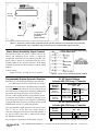
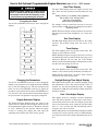
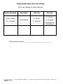
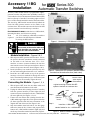
Accessory 11BG
for
Series 300
Installation
Automatic Transfer Switches
Accessory 11BG module includes a programmable engine–
generator exerciser and power source availability contacts. It
can be added to a Series 300 Automatic Transfer Switch (ATS)
that has a Group 1 Controller. If an existing engine exerciser
(Acc. 11CD) is already installed, it must be disconnected first.
The Accessory 11BG module mounts directly behind the
Series 300 ATS operator interface on the inside of the
enclosure door. The module connects to the Series 300 ATS
operator interface board and Group 1 controller.
Kits K629830 & K749999 include the Acc. 11BG module,
mounting hardware, and all necessary wiring.
Tools
required:
1/4”, 5/16” nutdrivers, small blade screwdriver
your Series 300 ATS Operator’s Manual
for setting the DIP switches
J1
Figure 1. Accessory 11BG Module in kits.
ELECTROCUTION – FLASH HAZARD
Do not work on the transfer switch until
both the utility and generator are off.
Turn OFF both circuit breakers.
Module Installation – Figures 2 & 3
1.
With all power OFF, open the enclosure door. Locate
the operator interface (membrane controls) mounted
on the inside of the enclosure door. Use a 5/16”
nutdriver to remove (counterclockwise) the four hex
nuts from the corners of the operator interface. Do not
remove the operator interface board (Figures 2 & 3).
2.
Install (clockwise) four standoffs (from the kit) onto
the four studs and tighten them with a 1/4” nutdriver.
3.
Install the Acc. 11BG module on top of the operator
interface so that four standoffs fit through the corner
holes. Then install (clockwise) four 6–32 hex nuts (from
the kit) to secure the assembly. Tighten the nuts.
J3
Figure 2. Series 300 ATS operator Interface board
mounted on the enclosure door (back view).
remove 4 nuts
(with captive
lockwashers)
Step 1
Connecting the Module – Figures 1, 2, 4
original mounting of Series 300 ATS
operator interface on enclosure door
1.
With all power OFF, locate the two ribbon cables and
note direction and orientation of each cable.
2.
Unplug the ribbon cable (coming from the Controller)
from the operator interface (J3 lower right side) and
reconnect it (same orientation) to the Acc. 11BG module
(J1 lower right side). See Figures 1, 2, & 4.
Step 2
Connect the new ribbon cable (coming from the Acc.
11BG module upper right side) to the operator interface
(J3 lower right side) with the same orientation as the
original cable that was moved. See Figures 2 & 4.
Step 3
3.
4.
Strip the insulation from both ends of the #16 gauge
white wire (from the kit). Connect this prepared wire
between Acc. 11BG module terminal 9 (right side) and
the Group 1 Controller terminal 4 (bottom left). Figure 4.
ASCO POWER TECHNOLOGIES L.P.
stud
add 4 standoffs
reinstall
4 nuts
operator
interface
board
install Acc. 11BG board
standoff added for Acc. 11BG Module
Figure 3. Module installation hardware.
50 Hanover Road, Florham Park, New Jersey 07932 USA
www.asco.com
381339–252 B
page 1
2–line
display
9
3 buttons
connections
for power source
availability
signal contacts
J3
J1
J1
wiring
Figure 4. Accessory 11BG module (mounted behind operator interface and connected to the controller)
includes power source availability signal contacts and a programmable engine exerciser.
Power Source Availability Signal Contacts
The module provides one Form C contact each for the
normal and emergency power sources to signal the
acceptability of the source as sensed by the controller. The
signal contacts operate in conjunction with the Source
Available lights on the operator interface. Field wiring
terminals are provided as shown in Figure 5 and the wiring
diagram.
Contact ratings:
2 amps @ 30 Vdc, 0.5 amp. @ 125 Vac resistive
Figure 5. Power source availability signal contacts.
Programmable Engine–Generator Exerciser
Note: Refer to your Series 300 ATS Operator’s Manual
to set DIP switches S1 & S2 in the Group 1 Controller.
ASCO POWER TECHNOLOGIES L.P.
Actuator 7 OFF
Actuator 8 ON
LOAD
EXER ACTV
LOAD
S2 DIP Switch Settings
in Series 300 ATS Group 1 Controller
Programmable
Exerciser
Function
ACTUATOR 5
OFF ON
Enabled
Actuator 5 OFF
Disabled
Actuator 5 ON
EXT EXER
5
page 2
Enabled &
Exercise
with Load
EXER ACTV
5
381339–252 B
Actuator 7 OFF
Actuator 8 OFF
8
See next page for instructions on setting the exerciser.
Enabled &
Exercise
without Load
7
The programmable engine–generator exerciser incorporates a 7–day or 14–day time base. Proper Group 1
Controller settings must be made to determine whether or
not the test will be done with or without load transfer
(S1 DIP switch actuator 8).
ACTUATORS 7 & 8
OFF ON
8
The Acc. 11BG module includes a programmable generator exerciser that provides for weekly or biweekly operation. The exerciser may have to be turned on (enabled) by
setting S1 DIP switch actuator 7 to OFF (left position), and
S2 DIP switch actuator 5 to OFF (left position).
Programmable
Exerciser
Function
7
A backup battery in the Series 300 ATS Group 1 Controller
(see Operator’s Manual, Sections 4 and 5) must be turned
on to maintain the settings and to allow programming with
the normal and emergency power sources turned off.
S1 DIP Switch Settings
in Series 300 ATS Group 1 Controller
EXT EXER
Shaded DIP switches are standard factory settings.
50 Hanover Road, Florham Park, New Jersey 07932 USA
www.asco.com
How to Set Optional Programmable Engine Exerciser (part of Acc. 11BG module)
Start Time Display
Hazardous voltage capable of causing shock,
burns, or death is used in this transfer switch.
Deenergize both Normal & Emergency power
sources before programming the exerciser.
Navigating the Menu
Use the UP and DOWN arrow keys to move through the
displays.
Fast/Slow Adjust
Daylight Saving
Time Adjust
Date
The Start Time Display shows the engine exerciser start
time. There are four parameters that determine the start
time:
weekly (”Every”) or bi–weekly (”Alt”) operation
day of week (”Sun” through “Sat”)
start hour (0 through 23)
start minutes (0 through 59)
For example, if the user wants the exerciser to run every
other Saturday at 3 PM, the proper configuration would be:
“Alt Sat @ 15:00”
NOTE: When choosing bi–weekly operation, the exerciser
will always run on the week designated “(1)” on the date
display.
Run Time Display
The Run Time Display shows the run time for the engine
exerciser. The default setting from the factory is 30
minutes.
Time Display
The Time Display shows the present system time. The
format is “hours:minutes:seconds”.
Time
NOTE: During total power outages, power to the accessory
is maintained by a battery in the Controller (see page 4–2 of
Operator’s Manual). Be sure that the 9–volt alkaline
battery is fresh and enabled (jumper in ON position) so that
the time and date settings are not lost.
Run TIme
Start TIme
Date Display
Engine Exerciser
The Date Display shows the present system date. The
format is “day of week (week) month/day of month/year”.
NOTE: Week is either week 1 or week 2. This is used in
conjunction with the bi–weekly timer.
Changing the Parameters
Daylight Savings Time Adjust Display
Use the UP and DOWN arrow keys to move though the
displays to the parameter to be changed. Push the ENTER
key to start the editing process. The first parameter will
flash. Use the UP and DOWN arrow keys to adjust the
parameter to the desired value and press the ENTER key to
save the value. The next parameter will now flash. Repeat
the process until each parameter is properly configured.
This display shows whether the automatic daylight saving
time adjustment is active. The factory default is “NO”. If
enabled, the unit will automatically adjust for daylight
saving time at 2 AM on the first Sunday of April and the last
Sunday of October.
Engine Exerciser Display
The Engine Exerciser Display shows the status of the
engine exerciser. When the unit is shipped from the factory
the programmable engine exerciser is “Disabled” and must
be set to “Enabled” by the customer. When the engine
exerciser is running, this display will count down the
remaining time until the end of the exercise period.
ASCO POWER TECHNOLOGIES L.P.
Fast / Slow Adjust Display
This display shows the automatic fast/slow adjustment
value. The factory default is 0. This feature can be used to
trim a clock that runs fast or slow. For example, if your clock
runs 10 seconds slow per week, change the fast/slow adjust
value to “+10” and the unit will automatically add 10
seconds to the clock every week.
NOTE: Adjustments are made Sunday morning at 2 AM. If
you want your exerciser period to start at 2 AM on Sunday,
you cannot use this feature and the adjustment must be set
to 0.
50 Hanover Road, Florham Park, New Jersey 07932 USA
www.asco.com
381339–252 B
page 3
Programmable Engine Exerciser Settings
Fill in your settings for future reference
Weekly or Bi–weekly
Every = weekly
Alt = bi–weekly
Day of Week
Sun through Sat
Start Time
0 – 23 hour
0 – 59 minute
Run Time
0 – 23 hour
0 – 59 minute
30 minutes is the
default setting
Date exerciser was set ______________________________________
381339–252 B
page 4
ASCO POWER TECHNOLOGIES L.P.
50 Hanover Road, Florham Park, New Jersey 07932 USA
www.asco.com