1
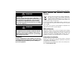
Radome Scanners
Users Guide
Document Number: 81256_4
Date: June 2006
Trademarks and registered trademarks
Autohelm, HSB, Raymarine, RayTech, RayTech RNS, Sail Pilot, SeaTalk and
Sportpilot are registered trademarks of Raymarine Limited. Apelco is a
registered trademark of Raymarine Holdings Limited (Registered in all
major marketing territories).
AST, Autoadapt, Auto GST, Autoseastate, Autotrim, Bidata, Marine Intelligence, Maxiview, On Board, Raychart, Raynav, Raypilot, Raystar, ST40,
ST60, Seaclutter, Smart Route, Tridata and Waypoint Navigation are trademarks of Raymarine Limited.
All other product names mentioned are trademarks or registered trademarks (if applicable) of their respective companies.
© Raymarine UK Ltd 2006
Contents
i
Contents
Important information ................................................................1
Introduction........................................................................................... 1
Intended use ......................................................................................... 1
Safety notices ........................................................................................ 1
WARNING: High voltage............................................................1
WARNING: Electromagnetic energy........................................1
WARNING: Product installation ...............................................1
Waste Electrical and Electronic Directive............................................... 2
EMC conformance ................................................................................. 2
Declaration of conformity...................................................................... 2
Display software version ....................................................................... 2
Warranty ............................................................................................... 2
Handbook information .......................................................................... 2
Installation ....................................................................................3
EMC installation guidelines................................................................... 3
Suppression ferrite............................................................................. 3
Connections to other equipment ....................................................... 3
What’s in the box? ................................................................................ 4
What tools do I need to install the scanner? ..................................... 4
How big is the scanner? ........................................................................ 5
18” Radome scanner ......................................................................... 5
24” Radome scanner ......................................................................... 5
Planning the installation ....................................................................... 6
Cable requirements ............................................................................... 7
Scanner cables ...................................................................................... 7
Running the cable to the scanner ...................................................... 7
Inter-unit cables................................................................................. 7
Power cables ......................................................................................... 8
Extending the power cable ................................................................ 8
Power requirements........................................................................... 8
Extending the power cable.................................................................... 9
Mounting options................................................................................ 11
Preparing the mounting holes ............................................................. 11
Securing the scanner to the mounting platform .................................. 12
Connecting the inter-unit cable to the scanner ................................... 13
Completing the installation ................................................................. 14
Display connections............................................................................. 15
Power connections........................................................................... 15
Inter-unit cable connections ............................................................ 16
Scanner setup...................................................................................... 16
Before you go to sea........................................................................ 16
EMC conformance............................................................................ 16
System checks.................................................................................. 16
Set up, alignment and timing checks ............................................... 17
Maintenance and troubleshooting ..........................................19
Introduction ..................................................................................... 19
Maintenance.................................................................................... 19
Troubleshooting............................................................................... 19
Technical support............................................................................. 20
Technical specification.............................................................. 21
RD218 18”Radome scanner unit ........................................................ 21
RD424 24”Radome scanner unit ........................................................ 23
ii
Radome Scanners - Users Guide
Important information
1
Important information
Introduction
Safety notices
This handbook contains an explanation of how to install, connect and
maintain your radome scanner and covers the following models:
• RD218 - 18” 2kW Radome scanner.
• RD424 - 24” 4 kW Radome scanner.
Your radar has been designed and manufactured to meet the rigorous
demands of the marine environment. However, no machine can perform its
intended function unless installed, operated and maintained properly.
Please carefully read and follow the recommended procedures for installation contained in this handbook.
When properly installed and operated, the use of this radar will conform to
the requirements of:
•
•
IEEE C95.1 - 1999 - Standard for Safety Levels with respect to Human
Exposure to Radio Frequency Electromagnetic Fields, 3 kHz to 300GHz.
ICNIRP Guidelines 1998 - International Commission on Non-Ionising
Radiation Protection: Guidelines for limiting exposure to time-varying
electric, magnetic and electro-magnetic fields (up to 300GHz) 1998.
WARNING
Radio Frequency Radiation Hazard
The radar antenna emits electromagnetic radio frequency
(RF) energy which can be harmful particularly to your eyes.
DO NOT look at the antenna at close range.
It is important that the radar is turned off whenever
personnel are required to come close to the scanner
assembly or associated equipment. It is recommended that
the radar scanner is mounted out of range of personnel
(above head height).
Distances from the face of the radar at which RF radiation
levels of 100 W/m2 and 10 W/m2 exist are given below
Model
Distance to 100 W/m2
point
Distance to 10 W/m2
point
RD218
Nil
Worst case
1.0m
RD214
Nil
Worst case
1.0m
Intended use
This product is a radar scanner intended for use within a navigational radar
system. The intended application is for leisure marine boats and work
boats not covered by IMO/SOLAS carriage requirements.
2
Radome Scanners - Users Guide
WARNING
High Voltage
The scanner unit contains high voltages. Adjustments
require specialized service procedures and tools only available to qualified service technicians - there are no user
serviceable parts or adjustments. The operator should
never remove the scanner unit internal covers or attempt
to sevice the equipment.
WARNING
Product installation
This equipment must be installed in accordance with the
instructions contained in this handbook. Failure to do so
could result in poor product performance, personal injury
and/or damage to your boat.
Waste Electrical and Electronic Equipment
Directive
The Waste Electrical and Electronic Equipment (WEEE) Directive requires the recycling of waste electrical and electronic
equipment. Whilst the WEEE Directive does not apply to some
of Raymarine’s products, we support its policy and ask you to
be aware of how to dispose of this product.
The crossed out wheelie bin symbol, illustrated above, and found on our
products signifies that this product should not be disposed of in general
waste or landfill.
Please contact your local dealer, national distributor or Raymarine Technical Services for information on product disposal.
EMC conformance
All Raymarine equipment and accessories are designed to the best industry
standards for use in the recreational marine environment. The design and
manufacture of Raymarine equipment and accessories conform to the
appropriate Electromagnetic Compatibility (EMC) standards, but correct
installation is required to ensure that performance is not compromised.
FCC Notice
Declaration of conformity
Changes or modifications to this equipment, not expressly
approved in writing by Raymarine Inc., could violate compliance withFCC rules and void the operator’s authority to
operate the equipment.
Raymarine UK Limited hereby declare that the products to which this
manual relates comply with the appropriate requirements and provisions
of the R&TTE Directive 1999/5/EC.
The full Declaration of Conformity may be viewed on the relevant product
pages at www.raymarine.com
Important information
Display software version
For operation of your scanner, the display unit requires the appropriate
software version. These are:
• E Series displays - Version 3.03 or later.
• C Series displays - Version 3.01 or later.
The software version can be confirmed by switching on the display and
checking the version number during the magnetron warm-up sequence.
However, if a scanner is not connected to the display, the version number
will only be displayed for 10 seconds.
Warranty
To register your new Raymarine product, please take a few minutes to fill
out the warranty card. It is important that you complete the owner information and return the card to receive full warranty benefits. Alternatively
you can register your product on line at www.raymarine.com
Handbook information
The technical and graphical information contained in this handbook, to the
best of our knowledge, was correct as it went to press. However, our policy
of continuous improvement and updating may change product specifications without prior notice. As a result, unavoidable differences between the
product and handbook may occur from time to time.
3
4
Radome Scanners - Users Guide
Installation
5
Installation
EMC installation guidelines
All Raymarine equipment and accessories are designed to the best industry
standards for use in the recreational marine environment.
Their design and manufacture conforms to the appropriate Electromagnetic
Compatibility (EMC) standards, but correct installation is required to
ensure that performance is not compromised. Although every effort has
been taken to ensure that they will perform under all conditions, it is
important to understand what facts could affect the operation of the
product.
The guidelines here describe the conditions for optimum EMC performance,
but it is recognized that it may not be possible to meet all of these conditions in all situations. To ensure the best possible conditions for EMC
performance within the constraints imposed by any location, always ensure
the maximum separation possible between different items of electrical
equipment.
For optimum EMC performance, it is recommended wherever possible:
•
•
Raymarine equipment and cables connected to it are:
• At least 3 ft. (1m) from any other equipment transmitting or
carrying radio signals. In the case of Single Side Band (SSB) radio,
the distance should be increased to 7 ft. (2m).
• More than 7 ft. (2m) from the path of a radar beam. A radar beam
can normally be assumed to spread 20 degrees above and below
the radiating element.
The equipment is supplied from a separate battery to that used for
engine start. Voltage drops below 10 V, and starter motor transients,
can cause the equipment to reset. This will not damage the equipment,
but may cause the loss of some information and may change the operating mode.
•
Raymarine specified cables are used. Cutting and rejoining these
cables can compromise EMC performance and must be avoided unless
doing so is detailed in the installation manual/
Suppression ferrite
If a suppression ferrite is attached to a cable, this
ferrite should not be removed. If the ferrite needs to
be removed during installation it must be reassembled in the same position.
D8852_1
The illustration shows typical cable suppression
ferrites used with Raymarine equipment. Always
use the ferrites supplied by Raymarine.
Connections to other equipment
If your Raymarine equipment is to be connected to other equipment using a
cable not supplied by Raymarine, a suppression ferrite MUST always be
attached to the cable near to the Raymarine unit.
6
Radome Scanners - Users Guide
What’s in the box?
What tools do I need to install the scanner?
Adhesive tape
Radome Scanner
Drill
Torque wrench
Artwork Number 3032-866-A
3026-136-A
Center Line of Radome
10 mm drill bit
Forward
13 mm socket
233 mm
Fixing bolts
and washers X4
Drill 4 holes, 10 mm diameter
(18'' and 24'' Radomes)
Inter-unit cable
Center Line of Radome
18'' or 24'' NGS Radome
Mounting Template
27.5 mm
Installation template
Components are dependant on your system package, but are either:
•
•
•
•
•
18” 2 kW Radome scanner and 15 m light cable, or
24” 4 kW Radome scanner and 15 m heavy cable.
Fixing bolts and washers.
Grease.
Handbook.
Philips screwdriver
D8853_1
141.5 mm
Grease
D8854_1
Installation
7
How big is the scanner?
24” Radome scanner
247 mm (9.7 in)
521 mm (20.5 in)
diameter
652 mm (25.67 in)
diameter
27.5 mm
(1.08 in)
141.5 mm
(5.57 in)
D8567-1
D8566-1
27.5 mm
(0.92 in)
141.5 mm
(5.57 in)
233 mm
(9.17 in)
346 mm (13.62 in)
diameter
116.5 mm
(4.58 in)
346 mm (13.62 in)
diameter
233 mm
(9.17 in)
116.5 mm
(4.58 in)
247 mm (9.7 in)
18” Radome scanner
8
Radome Scanners - Users Guide
Planning the installation
12.5˚
12.5˚
D8856_1
Mount the scanner so that the array rotates parallel to the waterline.
The radar beam is approximately 25o wide in the vertical direction, giving
good target detection when your boat pitches and rolls.
D8855_1
Mount the scanner as high as possible above the waterline for better long
range performance, but make sure it:
•
•
•
•
•
is above head height.
is easily accessible.
is as near to the boat’s centerline as possible.
is on a rigid and stable platform.
is clear of large objects such as the flybridge, large engine stacks,
searchlights, horns or masts.
• is clear of heat and fumes.
• is at least 1 m away from a magnetic compass or other equipment
antenna.
Don’t put the scanner so high, that it is affected by the pitching and rolling
of the boat.
Planing hull and
some displacement hull boats
adopt a higher
bow angle when
the boat is at
Forward
cruising speed.,
giving poor
target detection.
D8857_1
It may be necessary to lower the
radar beam back towards the parallel, by shimming the rear of the radar,
so that the beam points slightly down when the boat is at rest.
Wedge or
washers
Installation
9
Inter-unit cables
You need to consider the following points before installing the system
cables:
The inter-unit cable, illustrated below, is fitted with an 8-way plug and
power cores (covered with a clear protective sleeve) for connecting to the
scanner.
•
•
•
•
•
You need to connect the scanner to the display unit and power. The
cable required will depend on the display unit and scanner type.
All cables should be adequately clamped and protected from physical
damage and exposure to heat - avoid running cables through bilges or
doorways, or close to moving or hot objects.
Acute bends must be avoided.
Where a cable passes through an exposed bulkhead or deckhead, a
watertight gland or swan neck tube should be used.
Avoid cutting and rejoining cables. If this cannot be avoided refer to
Extending the power cable on page -11.
Scanner cables
A radome scanner connected to a C or E-Series display receives power via
the display unit.
Running the cable to the scanner
DO NOT pull the cable through bulkheads using a cord
attached to the connector. This could damage the
connections.
The cable entrance is at the rear of the scanner unit. If the unit is mounted
on a hollow mast, the cable may be run inside the mast and fed though the
unit’s cable entrance. Make sure that the cable does not chafe where it
enters and exits the mast.
To minimize electrical interference try to avoid running radar cables near
other on board electrical equipment. It is also good practice to avoid
running radar cables in parallel with power cables.
To display or extension
(power supplied via display unit)
To Radome Scanner
D8858_1
Cable requirements
The length of the cable supplied should be sufficient to complete the cable
run on most small boats. For longer runs, additional or replacement cables
are available. These cables have four power cores to minimize voltage
drops over the longer cable run.
Optional cable lengths available are:
• Part No. M92668 - 15 m heavy extension cable.
• Part No. M92669 - 25 m heavy replacement cable.
The maximum inter-unit cable length is limited by the minimum supply
voltage, the scanner type (18” or 24 “radome), and the cable type (2 or 4
power cores).
For boats with 12 V DC power systems details of recommended cable(s) for
different run lengths can be found in Extending the power cable on
page -11.
Boats with 24 V DC power systems can use any combination of inter-unit
cables.
10
Radome Scanners - Users Guide
Power cables
Radome radar systems are intended for use on boat’s DC power systems
operating in the range 10.7 to 32 V DC. That is 12 V and 24 V systems, they
should not be used on 32 V systems.
A 1.5 m (5ft) power cable is supplied with the display unit for connecting
the boat’s DC power to the radar scanner via the display unit.Refer to the
relevant display unit handbook for details on connecting this cable.
Extending the power cable
24 V power systems
If your boat has a 24 V power system, the power cable may be extended by
up to 20 m using a wire gauge of 1.5 mm2 (AWG 16) or greater, irrespective of the inter-unit cable length.
12 V power systems
If your boat has a 12 V power system, longer power cable runs may require
larger wire gauges to minimize any voltage drop in the cable.
For full details on extending the power cable and maximum permissible
lengths refer to Extending the power cable on page -11.
Power requirements
This radar is not recommended for use on ‘positive’ ground
boats. The power cable earth screen must be connected to
the boat’s ground.
The boat’s power system should be either:
•
•
Negative grounded, with the negative battery terminal connected to
the boat’s ground, or,
Floating with neither battery terminal connected to the boat’s ground.
Radome scanners receive power from the display via the inter-unit cable.
The display power cable is supplied with the display unit and details for
connecting power are detailed in the relevant Owner’s handbook.
Grounding the radar system
It is important that an effective radio frequency (RF) ground is connected to
the radar system.
You must ground the radar by connecting the drain wire (screen) of the
power cable to the nearest ground point of your boat’s RF ground system.
Full details can be found in the Owner’s Handbook for your display unit.
If you need to extend the wire, the extension wire should be an 8 mm braid
or 6 mm2 (AWG 10) multi-strand cable.
If your boat does not have an RF system, connect the drain wire to the
negative battery terminal.
11
Extending the power cable
12 V systems - Maximum permissible length for extending a power cable (m)
Inter-unit
cable type
Display
type
Power cable core (each core)
1.5
16
mm2
AWG
Radome size (ins)
10 m light
10 m light +
5 m ext
10 m light +
10 m ext
2.0
15
2.5
14
15 m heavy
6.0
10
10
7
18
24
18
24
18
24
18
24
18
24
18
24
C-Series
(6.0)
N/A
(7.0)
N/A
(9.0)
N/A
18.0
N/A
24.0
N/A
47.0
N/A
E-Series
(2.0)
N/A
(3.0)
N/A
(3.0)
N/A
7.0
N/A
9.0
N/A
18.0
N/A
C-Series
(4.0)
N/A
(5.0)
N/A
(6.0)
N/A
12.0
N/A
16.0
N/A
31.0
N/A
E-Series
(2.0)
N/A
(2.0)
N/A
(3.0)
N/A
6.0
N/A
8.0
N/A
16.0
N/A
C-Series
(1.0)
N/A
(2.0)
N/A
(2.0)
N/A
5.0
N/A
6.0
N/A
13.0
N/A
E-Series
15 m light
4.0
11
DO NOT EXTEND THE POWER CABLE
C-Series
(3.0)
N/A
(3.0)
N/A
(4.0)
N/A
9.0
N/A
11.0
N/A
23.0
N/A
E-Series
(1.0)
N/A
(2.0)
N/A
(2.0)
N/A
5.0
N/A
6.0
N/A
13.0
N/A
C-Series
(6.0)
(4.0)
(8.0)
(6.0)
(11.0)
(7.0)
21.0
14.0
27.0
19.0
50.0
37.0
E-Series
(2.0)
(1.0)
(3.0)
(2.0)
(4.0)
(2.0)
8.0
5.0
10.0
7.0
20.0
14.0
12
Radome Scanners - Users Guide
Inter-unit
cable type
15 m heavy
+5 m ext
Display
type
Power cable core (each core)
C-Series
(6.0)
(4.0)
(8.0)
(5.0)
(10.0)
(6.0)
20.0
13.0
26.0
17.0
50.0
34.0
E-Series
(2.0)
(1.0)
(3.0)
(2.0)
(4.0)
(2.0)
7.0
5.0
10.0
6.0
20.0
13.0
15 m heavy + C-Series
10 m ext
N/A
(3.0)
N/A
(4.0)
N/A
(5.0)
N/A
11.0
N/A
14.0
N/A
28.0
E-Series
N/A
(1.0)
N/A
(1.0)
N/A
(2.)0)
N/A
4.0
N/A
6.0
N/A
12.0
C-Series
(6.0)
(3.0)
(8.0)
(4.0)
(10.0)
(6.0)
20.0
11.0
25.0
15.0
50.0
29.0
E-Series
(2.0)
(1.0)
(3.0)
(1.0)
(3.0)
(2.0)
7.0
4.0
10.0
6.0
19.0
12.0
25 m heavy + C-Series
5 m ext
(6.0)
(2.0)
(7.0)
(3.0)
(9.0)
(3.0)
19.0
7.0
24.0
9.0
48.0
19.0
E-Series
(2.0)
(1.0)
(3.0)
(1.0)
(3.0)
(2.0)
7.0
4.0
9.0
5.0
18.0
10.0
25 m heavy + C-Series
10 m ext
(5.0)
(1.0)
(7.0)
(1.0)
(9.0)
(1.0)
17.0
3.0
22.0
4.0
44.0
9.0
E-Series
(2.0)
DO NOT
EXTEND
(2.0)
DO NOT
EXTEND
(3.0)
DO NOT
EXTEND
7.0
DO NOT
EXTEND
9.0
DO NOT
EXTEND
17.0
DO NOT
EXTEND
25 m heavy
13
Mounting options
Preparing the mounting holes
-8
32
r 30
36
be
30
Ar
tw
or
k
26
-1
Mounting platform
Num
-A
66
-A
1
m
do
Ra
S te
NG pla
4' Tem
2
r g
' o tin
18 un
o
M
in
rL
te
27.5
ete
m
dia
m )
m es
10 om
s, ad
le R
ho 24'
ll 4 nd
ri
a
D '
8
(1
n
Ce
m
5m
FORWARD
141.
r
e
23
3
of
m
m
Ra
do
n
Ce
m
te
e
rL
in
e
e
of
Ra
do
m
e
ard
rw
Fo
D
R
A
W
R
FO
Mounting platform
mm
2
FORWARD
D8859_1
Mounting platform
1. Tape template to mounting
platform.
2. Using template, drill 10 mm
diameter hole in 4 positions.
IMPORTANT
Ensure mounting
platform is
adequately robust
for this
installation.
D8860_1
1
2
14
Radome Scanners - Users Guide
D8861_1
FO
R
W
A
R
D
Securing the scanner to the mounting platform
15
Connecting the inter-unit cable to the scanner
CAUTION: Connections
Before starting to connect the inter-unit cable make
sure that the cable is not connected and power is not
applied to the display unit.
With the radome cover removed:
1. Remove the inner cover (1).
2. Slide the gland nut and grommet onto the inter-unit cable (2),
and insert the cable, still covered by its protective sleeve,
through the gland.
3. Carefully cut and remove the protective sleeve to expose the 8way plug (3) and the power cores (5).
4. Connect the red (+ve) and black (-ve) power cores (5). If you
have a 10m light or 15m inter-unit cable, connect both pairs of
cores to the relevant terminals.
5. Connect the 8-way plug (3) to the connector (4). The plug will
only fit one way.
6. Replace the inner cover (1), making sure that the exposed wire
braid (6) is secured in the cable clamp of the casting.
7. Clip the inter-unit cable into the strain relief (7).
8. Secure the nut on the watertight gland, making sure that it
grips the outer sheath of the cable.
9. Replace the radome cover - See “Completing the installation”
on page 16..
2
3
1
7
4
+ ve
- ve
5
D8862_1
6
16
Radome Scanners - Users Guide
Completing the installation
D8863_1
1. Holding the cover securely, remove the cord and toggle from the
retaining hole.
2. Coil and place the cord in the storage compartment.
Secure in place by fixing the toggle on top of the cord
(see inset).
3. Place cover onto the base unit ensuring the markers
are aligned - see right.
4. Tighten the captive screws just sufficiently to secure.
DO NOT OVERTIGHTEN.
5. Ensure nut is tightened sufficiently to enable gland to
make a watertight seal around the cable
D8984_1
CAUTION: Toggle and cord
Make sure the toggle and cord is correctly stowed before
replacing the radome cover. Failure to do so will result in the
antenna being unable to operate.
17
Display connections
The inter-unit cable is connected to the display unit with the molded plug:
the illustration on the left identifies the scanner connection on the rear
connector panels of the various display units.
G
Y
If you are using an inter-unit extension cable, connect this to the display
unit, and connect the supplied cable to the extension cable.
DSM
R
NMEA
IN/OUT
SEATALK 2
RADAR
SEATALK 2
SEATALK
C Series display
Power connections
Scanner
Power for your radome scanner when it is connected to a C or E-Series
display is supplied via the display unit - refer to the relevant display unit
Owner’s Handbook for full details.
E Series display
You will need to make the following connections to your boat’s DC power
supply:
Red - Battery +ve (12/24 V)
Black - Battery -ve (0 V)
D8865_1
Ground
Scanner
D8864_1
18
Radome Scanners - Users Guide
Inter-unit cable connections
Scanner setup
The illustration below details the connections for the inter-unit cable:
Before you go to sea
Front view of
Display Cable Connector
8
7
1
2
5
3
4
8
6
7
11
9
13
10
12
4
3
2
Not fitted on
Open Array Scanners
(refer to Section 2.2)
Scanner
Video
1
Video RTN
2
*Battery --ve 3
Tx Trigger +
4
Battery --ve
5
Data I/O +
6
Tx Trigger --
Set up, alignment and timing checks are performed from the radar system
display unit. The procedures are outlined on this page; full details are available in the relevant display unit Owner’s Handbook. You should read this
and familiarize yourself with the operation of the radar.
6
5
1
Display
After you have installed your radar, and before you go to sea, it is important to check the installation. You can then set up the radar system, align
the scanner and check the system timing.
Front view of Radome
Scanner Cable Connector
7
8
Battery +ve
9
Data I/O --
10
*Battery +ve 11
Azimuth +
12
Azimuth --
13
White
White
Black
Black
Black
Orange
Orange
Yellow
Black
Green
Green
Blue
Yellow
Violet
Shield
Grey
Red
Red
Red
Violet
Black
Grey
Black
System checks
7 Video Rtn
System check
6 Tx Trigger +
Before performing any functional tests, make sure:
5 Tx Trigger --
•
4 Data I/O +
3 Data I/O -2 Azimuth +
1 Azimuth --
Battery +ve
*Battery +ve
*Battery --ve
Battery --ve
Battery +ve/--ve = 12 or 24v.
* Not present on 'light', 11 core cables.
Always check the installation before going to sea to make sure that it is not
affected by radio transmissions, engine starting, etc.
8 Video
Red
Blue
EMC conformance
D8866_1
All securing bolts are fully tightened and mechanical locking devices as
specified are in place.
• All connections have been made.
• All connecting wires are secured and protected as necessary.
If you have installed the radar yourself, ask your local Raymarine authorized installation dealer to check the installation.
19
Set up, alignment and timing checks
Switch on and initial set up
1. Press and hold the POWER key of the display unit until the unit beeps.
The magnetron warm-up sequence should start, after which the unit
should enter standby mode.
2. If necessary, adjust the lighting and contrast.
3. If necessary, change the default language settings.
Transmission check
Ensure that all personnel are clear of the scanner and switch to transmit
mode. Run through the radar operations as described in the relevant
display unit’s Owner’s Handbook and check that all the expected data is
displayed.
Bearing alignment
With the system correctly installed, check the bearing alignment to ensure
that targets appear at their correct bearing relative to the boat’s bow.
Adjust the alignment as necessary.
Display timing adjustment
The display timing can be affected by the length of cable used to connect
the scanner to the display unit. This in turn affects the short range accuracy
shown on the display.
It is advisable to check the display timing before using the system for
navigation.
20
Radome Scanners - Users Guide
Maintenance and troubleshooting
21
Maintenance and troubleshooting
CAUTION: System power
Always turn the radar system OFF before carrying out any
routine maintenance on the scanner or nearby equipment.
Switch off the display unit before removing the power cord.
Troubleshooting
The table below identifies the most likely cause and the corrective action
required to restore normal operation.
Introduction
Problem
Solution
DO NOT remove the rear cover of the display or the internal covers in the
scanner. There are no user serviceable parts or adjustments. DO NOT
attempt to service the equipment.
“Scanner not responding”
message
1. Check that the cable connecting the
scanner to the radar display unit is
firmly attached and undamaged.
2. Check that the polarity of the cables
is correct.
The bearing displayed on the
radar display is not the same
as the actual bearing.
Perform the bearing alignment procedure described in the relevant display
unit Owner’s handbook.
Maintenance
Maintenance is limited to the following periodical checks:
•
•
•
•
•
Examine the cables for signs of damage, such as chafing, nicks and
cuts.
Check that the cable connectors are firmly attached.
Remove the scanner cover and check for signs of water damage.
Make sure the scanner is still securely attached to the mounting
surface.
Once a year, remove, grease and re-attach the mounting bolts securing
the scanner.
If you still have a problem after referring to this table, contact your local
dealer, national distributor or Raymarine Product Support Department for
further advice.
Always quote the product serial number. The display unit serial number can
be found on the back of the unit, the scanner serial number can be found
on the back of the scanner near the gland.
22
Radome Scanners - Users Guide
Technical support
www.raymarine.com
United States
Europe
Raymarine Technical Support
1-800-539-5539 extension 2444, or
(603) -881-5200
Technical Support
Services
Accessories
Product Repair and Service
Raymarine Product Repair Center
21 Manchester Street,
Merrimack, NH03054 - 4801
1-800-539-5539
Raymarine UK Limited
Anchorage Park
Portsmouth
PO3 5TD
England
Opening hours:
Monday through Friday 0815 - 1700
Eastern Standard or Eastern Daylight
Savings Time.
Tel:
+44(0)23 9271 4713
Fax:
+44(0)23 9266 1228
Help us to help you
When requesting service, please quote the following product information:
Equipment type Model number Serial number
D8867_1
23
Appendix A: Technical specification
RD218 18”Radome scanner unit
General
Transmitter
Transmitter Frequency
9410 +/– 30 MHz
Approvals
CE - conforms to
FCC - conforms to
Peak Power Output
2.0 kW (nominal)
1999/5/EC
47CFR Part 2 and Part 80
Transmitter
Solid-state modulator driving Magnetron
Dimensions
Φ521 x 247 mm (20.5 x 9.7 in)
Pulse Length/PRF
Weight
9.5 kg (21 lbs)
Input Voltage
8.7 - 32 V DC (from display unit)
Power Consumption
Environmental
Maximum Range Scale
Range (nm)
Pulse Length (ns)
PRF (kHz)
0.25 or less
75
3.0
0.50
100
3.0
28 W (9 W Standby)
0.75
150
3.0
Waterproof to CFR46
Temperature range:
-10° to +55°C
Humidity limit:
up to 95% at 35°C
Maximum wind speed for satisfactory operation:
100 Kts
0.75 expanded
250
2.5
1.50
350
1.8
24 nm
3.00
450
1.4
3.00 expanded
600
1.0
6.00 or greater
1.0 μs
740 Hz
Standby Mode
magnetron heater and control left on, all other
services off
Duplexer
Circulator
24
Pathfinder Radomes - Users Handbook
Antenna
Antenna Type
Patch array
Beam Width (nominal)
4.9° horizontal, 25° vertical
Polarization
Horizontal
Rotation Rate
24 rpm (nominal)
Receiver
IF Frequency
60 MHz (nominal)
Receiver Characteristic
Logarithmic
Receiver Noise Figure
Less than 5 dB
(including Low Noise Converter/Limiter & IF
Receiver)
Receiver Bandwidth
12/3/0.7/0.5 MHz
25
RD424 24”Radome scanner unit
Transmitter
Pulse Length/PRF
General
Range (nm)
Pulse Length (ns)
PRF (Hz)
1999/5/EC
47CFR Part 2 and Part 80
0.25 or less
75
3.0
0.50
100
3.0
Dimensions
Φ652 x 247 mm (25.67 x 9.7 in)
0.75
150
3.0
Weight
10.0 kg (22 lbs)
0.75 expanded
250
3.0
Input Voltage
8.7 - 32 V DC (from display unit)
1.50
350
2.0
Power Consumption
34 W (10 W Standby)
3.00
450
1.5
Environmental
Waterproof to CFR46
Temperature range: -10° to +55°C
Humidity limit:
up to 95% at 35°C
Maximum wind speed for satisfactory operation: 100 Kts
3.00 expanded
600
1.3
6.00 or greater
1.0 μs
740 Hz
Standby Mode
Magnetron heater and control left on, all other services off
Duplexer
Circulator
Approvals
CE - conforms to
FCC - conforms to
Maximum Range Scale
48 nm
Transmitter
Antenna
Transmitter Frequency
9410 +/– 30 MHz
Peak Power Output
4.0 kW (nominal)
Transmitter
Solid-state modulator driving Magnetron
Antenna Type
Patch array
Beam Width (nominal)
3.9° horizontal, 25° vertical
26
Pathfinder Radomes - Users Handbook
Antenna
Polarization
Horizontal
Rotation Rate
24 rpm (nominal)
Receiver
IF Frequency
60 MHz (nominal)
Receiver Characteristic
Logarithmic
Receiver Noise Figure
Less than 5 dB
(including Low Noise Converter/Limiter & IF Receiver)
Receiver Bandwidth
12/3/0.7/0.5 MHz