1
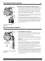
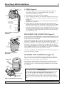
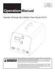
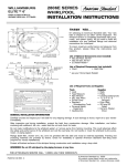
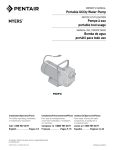
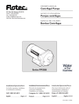
OWNER’S MANUAL
®
Convertible Deep Well Jet Pumps
and Tank System
293 Wright St., Delavan, WI 53115
Phone: 1-800-468-7867
1-800-546-7867
Fax:
1-800-390-5351
Web Site: http://www.simerpump.com
4025 0801
Mod. Nos. 2805E-01, 2806E-01,
2810E-01, 2815E-01
Installation/Operation/Parts
For further operating, installation, or
maintenance assistance:
Call 1-800-365-6832
English . . . . . . . . . . . . . Pages 2-14
©2002 PRINTED IN U.S.A.
1000000171 (Rev. 6/27/02)
Safety
2
READ AND FOLLOW
SAFETY INSTRUCTIONS!
This is the safety alert symbol. When you see this
symbol on your pump or in this manual, look for
one of the following signal words and be alert to the
potential for personal injury:
warns about hazards that will cause serious
personal injury, death or major property damage if
ignored.
warns about hazards that can cause serious
personal injury, death or major property damage if
ignored.
warns about hazards that will or can cause
minor personal injury or property damage if ignored.
The label NOTICE indicates special instructions which
are important but not related to hazards.
ELECTRICAL SAFETY
Hazardous voltage. Can shock, burn or
kill. Capacitor voltage may be hazardous. To discharge
the motor capacitor, hold the insulated handle screwdriver BY THE HANDLE and short the capacitor terminals together. Do not touch the metal screwdriver blade
or capacitor terminals. If in doubt, consult a qualified
electrician.
GENERAL SAFETY
Burn hazard. Do not touch an operating
motor. Modern motors are designed to operate at high
temperatures. To avoid burns when servicing pump,
allow it to cool for 20 minutes after shut-down before
handling.
Do not allow the pump or any system component to
freeze. To do so will void the warranty.
Pump water only with this pump.
Carefully read and follow all safety instructions in this
manual and on pump.
Periodically inspect the pump and system components.
Keep safety labels in good condition.
Replace missing or damaged safety labels.
Keep the work area clean, uncluttered and properly lighted; store properly all unused tools and equipment.
Wear safety glasses at all times when working on pumps.
Keep visitors at a safe distance from the work areas.
Hazardouse pressure. Risk of explosion.
Pump body may explode if used as a booster pump
unless a relief valve capable of passing the full pump
flow at 75 psi is installed.
WARNING
Wire motor for correct
voltage. See “Electrical” section of this manual
and motor nameplate.
Ground motor before
connecting to power
supply.
Hazardous voltage.
Can shock, burn, or
cause death.
Ground pump before
connecting to power
supply. Disconnect power
before working on pump,
motor or tank.
WARNING
Hazardous pressure!
Install pressure relief
valve in discharge pipe.
Release all pressure on
system before working on
any component.
Meet National Electrical Code, Canadian
Electrical Code, and local
codes for all wiring.
Follow wiring instructions in this manual
when connecting motor to
power lines.
For parts or assistance, call Simer Customer Service at 1-800-468-7867
/ 1-800-546-7867
Table of Contents
3
Thank you for purchasing a top quality, factory tested pump.
Page
General Safety .....................................................................................................2
Warranty ..............................................................................................................3
Replacing an Existing Pump.................................................................................4
New Shallow Well Installation..........................................................................5,6
• Well Point (Driven Point)
• Cased Well, 2” or larger casing
• Installation for Surface Water
New Deep Well Installation..............................................................................6,7
• 4” or Larger Well
• 2” Well
• Pre-charged Tank Connection
• Standard Tank Connection
Electrical ...........................................................................................................8,9
Preparing To Start The Pump – Deep Well .........................................................10
Preparing To Start The Pump – Shallow Well .....................................................11
Troubleshooting..................................................................................................12
Repair Parts ..................................................................................................13,14
Simer Limited Warranty
SIMER warrants to the original consumer purchaser (“Purchaser”) of its products
that they are free from defects in material or workmanship.
If within twelve (12) months from the date of the original consumer purchase
any such product shall prove to be defective, it shall be repaired or replaced at
SIMER’s option, subject to the terms and conditions set forth below. Your original receipt of purchase is required to determine warranty eligibility.
Exceptions to the Twelve (12) Month Warranty
Five (5) Year Warranty:
If within five (5) years from original consumer purchase any Pre-Charge water
system tank shall prove to be defective, it shall be repaired or replaced at
SIMER’s option, subject to the terms and conditions set forth below.
General Terms and Conditions
Purchaser must pay all labor and shipping charges necessary to replace product
covered by this warranty. This warranty shall not apply to acts of God, nor shall
it apply to products which, in the sole judgement of SIMER, have been subject
to negligence, abuse, accident, misapplication, tampering, alteration; nor due
to improper installation, operation, maintenance or storage; nor to other than
normal application, use or service, including but not limited to, operational failures caused by corrosion, rust or other foreign materials in the system, or operation at pressures in excess of recommended maximums.
Requests for service under this warranty shall be made by returning the defective product to the Retail outlet or to SIMER as soon as possible after the discovery of any alleged defect. SIMER will subsequently take corrective action as
promptly as reasonably possible. No requests for service under this warranty
will be accepted if received more than 30 days after the term of the warranty.
This warranty sets forth SIMER’s sole obligation and purchaser’s exclusive remedy for defective products.
SIMER SHALL NOT BE LIABLE FOR ANY CONSEQUENTIAL, INCIDENTAL, OR
CONTINGENT DAMAGES WHATSOEVER.
THE FOREGOING WARRANTIES ARE EXCLUSIVE AND IN LIEU OF ALL
OTHER EXPRESS WARRANTIES. IMPLIED WARRANTIES, INCLUDING BUT
NOT LIMITED TO THE IMPLIED WARRANTIES OF MERCHANTABILITY AND
FITNESS FOR A PARTICULAR PURPOSE, SHALL NOT EXTEND BEYOND THE
DURATION OF THE APPLICABLE EXPRESS WARRANTIES PROVIDED HEREIN.
Some states do not allow the exclusion or limitation of incidental or consequential damages or limitations on how long an implied warranty lasts, so the
above limitations or exclusions may not apply to you. This warranty gives you
specific legal rights and you may also have other rights which vary from state
to state.
SIMER • 293 Wright St. • Delavan, WI U.S.A. 53115
Phone: 1-800-468-7867 / 1-800-546-7867 • Fax: 1-800-390-5351
Replacing an Existing Pump
4
SHALLOW WELL (Figure 1)
Control Valve
Port plugged
Pressure Gauge
Port plugged
hold
Hazardous voltage. Can shock, burn or kill. Disconnect power
to pump before working on pump or motor.
e
ous
To H
1. Drain and remove the old pump. Check the old pipes for scale, lime,
rust, etc., and replace them if necessary.
Shallow Well
Injector Installed
Fro
mW
Drive Pipe
Port plugged
ell
4026 0801
Figure1: Shallow Well Setup
3. Adjust the pump mounting height so that the plumbing connections do
not put a strain on the pump body. Support the pipe so that the pump
body does not take the weight of piping or fittings.
DEEP WELL
Install Control
Valve
Install
Pressure
Gauge
2. Install the pump in the system (see Figures 4, 5, and 6). Make sure that
all of the pipe joints in the suction pipe are air-tight as well as water
tight. If the suction pipe can suck air, the pump will not be able to pull
water from the well.
Hazardous voltage. Can shock, burn or kill. Disconnect the
power to the pump before working on pump or motor.
ld
eho
ous
To H
Drive Pipe
To Well
Installed
Fro
1. Drain and remove the old pump. Check the pipes for scale, lime, rust,
etc., and replace them if necessary.
Remove Shallow Well
Injector and Install
Deep Well Plug
ell
mW
4032 0801
Figure 2: Deep Well Setup
2. Install the control valve, pressure gauge, and deep well plug in the
pump body (purchase kit separately; see Figure 2). When connecting to
the well head, be sure you go small port to small port (drive) and large
port to large port (suction). If necessary, use flexible pipes and twist
them to make the correct connections.
3. Simer pumps have the suction pipe (the larger port) below the drive port
(see Figures 2 and 3).
4. Install the pump in the system. Make sure all of the pipe joints in the
suction pipe are air-tight as well as water tight. If the suction pipe can
suck air, the pump will not be able to pull water from the well.
5. Adjust the pump mounting height so that the plumbing connections do
not put a strain on the pump body. Support the pipe so that the pump
body does not take the weight of piping or fittings.
Discharge Port
Drive Port
The Drive Pipe
sends the water
down the well
and drives the
water up through
the Suction Pipe
to the Pump
Suction Port.
NOTICE: Your old injector system (in the well) may not be properly
matched to your new pump. If your pump does not perform properly,
we recommend that you install a Simer MDWE Injector Kit (4” well) or
a Simer MDWA Injector Kit (2” packer-type well).
Suction Port
1799 0497 SIM
Figure 3: Deep Well Drive and
Suction Functions
For parts or assistance, call Simer Customer Service at 1-800-468-7867
/ 1-800-546-7867
New Shallow Well Installation
5
SHALLOW WELL JET PUMP INSTALLATIONS
Relief
Valve
To Household
Water System
Check
Valve
• Have a vertical depth between the pump and the water being pumped
of 25’ or less.
• Have one pipe from the well to the pump case.
• Can be installed in a bored or drilled well, or in a driven well.
Priming
Tee and
Plug
Drive point below
water level
Not
to
Scale
Drive
Coupling
Drive
Point
2097 0497 SIM
Relief
Valve
To Household
Water System
Suction Pipe
From Well
Priming
Tee and
Plug
Sanitary
Well Seal
Well
Casing
Not
to
Scale
4033 0801
5-10'
Strainer
2. Mount the pump as close to the well as possible.
CASED WELL INSTALLATION, 2” OR LARGER
CASING (Figure 5)
1. Mount the pump as close to the well as possible.
Check
Valve
Foot
Valve
1. Drive the well, using “drive couplings” and a “drive cap”. “Drive fittings” are threaded all the way through and allow the pipe ends to butt
against each other so that the driving force of the maul is carried by the
pipe and not by the threads. The ordinary fittings found in hardware
stores are not threaded all the way through the fitting and can collapse
under impact. “Drive fittings” are also smoother than standard plumbing
fittings, making ground penetration easier.
3. Use the fewest possible fittings (especially elbows) when connecting the
pipe from the well point to the pump suction port. The suction pipe
should be at least as large as the suction port on the pump (include a
check valve). Support the pipe so that there are no dips or sags in the
pipe, so it doesn’t strain the pump body, and so that it slopes slightly
upward from the well to the pump (high spots can cause air pockets
which can air lock the pump). Seal the suction pipe joints with teflon
tape. Joints must be air- and water-tight. If the suction pipe can suck air,
the pump cannot pull water from the well. If one well point does not
supply enough water, consider connecting two or three well points to
one suction pipe.
Figure 4:Typical Well-Point
Installation
At least
10'
WELL POINT INSTALLATION (Figure 4)
2. Assemble the foot valve, strainer, and well pipe. Make sure that the foot
valve works freely.
3. Lower the pipe into the well until the strainer is five feet above the bottom of the well. It should also be at least 10 feet below the well’s water
level while the pump is running in order to prevent the pump from
sucking air. Install a sanitary well seal.
4. Install a priming tee, priming plug, and suction pipe to the pump.
Connect the pipe from the well to the pump suction port, using the
fewest possible fittings (especially elbows) as fittings increase friction in
the pipe. The suction pipe should be at least as large as the suction port
on the pump. Use teflon tape on threaded pipe joints. Joints must be airand water-tight. If the suction pipe can suck air, the pump cannot pull
water from the well. Support the pipe so that there are no dips or sags in
the pipe, so it doesn’t strain the pump body, and so that it slopes slightly
upward from the well to the pump (high spots can cause air pockets
which can air lock the pump).
Figure 5:Typical Cased Well
Installation
For parts or assistance, call Simer Customer Service at 1-800-468-7867
/ 1-800-546-7867
New Shallow Well Installation
Relief
Valve
To Household
Water System
Check
Valve
Suction Pipe
From Well
Priming
Tee and
Plug
10'
Min.
Not
to
Scale
Foot
Valve
5–10'
Screen
6
INSTALLATION FOR SURFACE WATER (Figure 6)
1. The pump should be installed as close to the water as possible, with the
fewest possible fittings (especially elbows) in the suction pipe. The suction pipe should be at least as large as the suction port on the pump.
2. Assemble a foot valve and suction pipe. Make sure that the foot valve
works freely. Use Teflon tapeTM. Protect the foot valve assembly from
fish, trash, etc, by installing a screen around it.
3. Lower the pipe into the water until the strainer is five feet above the bottom. It should also be at least 10 feet below the water level in order to
prevent the pump from sucking air.
4. Install a priming tee, priming plug, and suction pipe to the pump.
Support the pipe so that there are no dips or sags in the pipe, so it doesn’t strain the pump body, and so that it slopes slightly upward from the
well to the pump (high spots can cause air pockets which can air lock
the pump). Seal the suction pipe joints with teflon tape. Joints must be
air and water tight. If the suction pipe can suck air, the pump cannot
pull water from the well.
4034 0801
Figure 6:Typical Open Water
Installation
New Deep Well Installation
Relief
Valve
To Household
Water System
1. Install the control valve, the pressure gauge and the deep well injector
plug in the pump body. See Figure 2. Purchase Model MDWC Deep
Well Conversion Kit to obtain these parts.
2. Mount the pump as close to the well as possible.
Drive Pipe
To Well
3. Install a flexible pipe between the well head and the pump so the connection will be correct. Connect small port to small port and large port
to large port.
NOTICE: Simer jet pumps have the suction port (the larger port) below
the drive port. See Figure 3.
Suction Pipe
From Well
Well
Head
4. Connect both the suction and drive pipes to the ejector piping and
lower the ejector into the well until it is five feet from the bottom. It
should also be at least 10 feet below the well’s water level while the
pump is running in order to prevent the pump from sucking air.
If well head and pump
ports don't match, twist
reinforced flexible pipe
to make connections.
Not
to
Scale
4” OR LARGER WELL (Figure 7)
Venturi
Ejector
5. Install a sanitary well seal and connect the ejector piping to the pump.
Use steel nipples through the well seal with flexible poly pipe to avoid
crushing the plastic pipe when tightening the seal.
Nozzle
Foot Valve
Strainer
4035 0801
Figure 7:Typical 2” and 4” Deep Well
Installation
6. Support the pipe so that there are no dips or sags in the pipe, so it doesn’t strain the pump body, and so that it slopes slightly upward from the
well to the pump (high spots can cause air pockets which can air lock
the pump). Seal the suction pipe joints with teflon tape. Joints must be
air- and water-tight. If the suction pipe can suck air, the pump cannot
pull water from the well.
For parts or assistance, call Simer Customer Service at 1-800-468-7867
/ 1-800-546-7867
New Deep Well Installation
Relief Valve
7
2” WELL (Figure 8)
To Household
Water System
1. Install the control valve, pressure gauge, and deep well plug in the
pump body. See Figure 2. Purchase Model MDWC Deep Well
Conversion Kit to obtain these parts.
Well Head
2. Mount the pump as close to the well as possible.
Drive Pipe
To Well
3. Install a flexible pipe between the well head and the pump so the connection will be correct. Connect small port to small port and large port
to large port.
NOTICE: Simer jet pumps have the suction port (the larger port) below
the drive port. See Figure 3.
Well Casing
serves as
Drive Pipe
Suction Pipe
From Well
Suction Pipe
If well head and pump
ports don't match, twist
reinforced flexible pipe
to make connections.
JET NO.
Not
to
Scale
4. Run the drive pipe and the suction pipe from the well to the pump.
Support the pipe so that there are no dips or sags in the pipe, so it doesn’t strain the pump body, and so that it slopes slightly upward from the
well to the pump (high spots can cause air pockets which can air lock
the pump). Seal the suction pipe joints with Teflon tapeTM. Joints must be
air- and water-tight. If the suction pipe can suck air, the pump cannot
pull water from the well.
J32P- 24
Venturi
Nozzle
41
4035 0801
Ejector
Leather
Cup Seals
4036 0801
Figure 8:Typical 2” Deep Well
Installation
Relief Valve
PRE-CHARGE TANK CONNECTION (Figure 9)
If your system uses a pre-charged tank, it should be connected to the pump
as shown in Figure 9. The relief valve must be capable of passing the entire
pump capacity at 100 PSI pressure.
To the Household
Water System
Drive Pipe
To the Well
Check the pre-charge of the air in the tank with an ordinary tire gauge. The
pre-charge is measured when there is no water pressure in the tank.
Disconnect the power to the pump and drain the tank before checking the
pre-charge. Your pump has a 20/40 PSI switch (Models 2805/6/10E) or a
30/50 PSI switch (Model 2815E), so the tank pre-charge pressure should be
18 PSI (Models 2805/6/10E) or 28 PSI (Model 2815E). That is, it should be 2
PSI lower than the cut-in pressure of the pressure switch.
Pressure
Switch
Plugged
AVC
Port
Suction Pipe
From the Well
To
Waste
NO AVC is required for a pre-charged tank; the 1/4” NPT AVC port on the
pump body should be plugged.
2110 0497 SIM
Figure 9: Pre-charged Tank
Connections
To Household
Water System
Pressure
Switch
STANDARD TANK CONNECTION (Figure 10)
If your system uses a standard tank, connect it to the pump as shown in
Figure 10. The relief valve used with a standard tank must be capable of
passing the entire pump capacity at 75 PSI pressure.
Air Volume
Control
Connect the Air Volume Control (AVC) tube to the 1/4” NPT AVC port on
the pump body. Run the tubing from the pump’s AVC port to the AVC
mounted on the tank. See the instructions provided with the tank and the
AVC for details.
Air Volume
Control Tube
Relief
Valve
Drive Pipe To Well
Suction Pipe
From Well
Figure 10: Standard Tank Connections
2
Sealing Pipe Joints
Use only Teflon tape for making all threaded connections to the pump
itself. Do not use pipe joint compounds on plastic pumps: they can
react with the plastic in pump components. Make sure that all pipe
joints in the suction pipe are air tight as well as water tight. If the suction pipe can suck air, the pump will not be able to pull water from the
well.
For parts or assistance, call Simer Customer Service at 1-800-468-7867
/ 1-800-546-7867
Electrical
8
Hazardous voltage. Can shock, burn or kill. Disconnect the power before working on pump, motor,
pressure switch, or wiring.
Your Motor Terminal Board (under the motor end cover)
and Pressure Switch look like one of those shown below.
Convert to 115 Volts as shown. Do not change motor
230 Volt to 115 Volt Conversion. Move plug to change voltage.
Ground
Screw
230 V
A
230V
115V
230V
115V
230V
115V
230V
115V
115 V
L2
A
wiring if line voltage is 230 Volts or if you have a single
voltage motor. Connect power supply as shown for your
type of switch and your supply voltage.
Motor wires connect here.
Power supply wires connect here.
230 Volt: Connect 2 hot wires (black and red)
here and cap the white (neutral) wire. It does
not matter which wire goes to which screw.
115 Volt: Connect one hot wire (black or red)
to one of these screws (it doesn't matter
which one). Connect the white (neutral) wire
to the other screw. Cap any remaining
black or red wires.
L2
Clamp the power cable to prevent strain
on the terminal screws.
L1
L1
Power Supply
Wires
Connect the green (or bare copper) ground wire
to the green ground screw.
230 Volt to 115 Volt Conversion. Move plug to change voltage.
1. Pull plug
straight
out from
terminal
board.
2. Plug in again
with arrow
on plug
pointing to
'115 Volts'.
230
Volts
230
Volts
A
2.
115
Volts
115
Volts
A
1.
Ground
Screw
L1
Motor wires connect here.
Power supply wires connect here.
230 Volt: Connect 2 hot wires (black and red)
here and cap the white (neutral) wire. It does
not matter which wire goes to which screw.
115 Volt: Connect one hot wire (black or red)
to one of these screws (it doesn't matter
which one). Connect the white (neutral) wire
to the other screw. Cap any remaining
black or red wires.
Clamp the power cable to prevent strain
on the terminal screws.
L1
3962 0401 A
Connect the green (or bare copper) ground wire
to the green ground screw.
3187 0398
Figure 11: Motor wiring connections through Pressure Switch. Match motor voltage to line voltage
Hazardous voltage. Can shock, burn, or kill. Connect ground
wire before connecting power supply wires. Use the wire size (including
the ground wire) specified in the wiring chart. Connect the pump to its
own dedicated branch circuit with no other appliances on it.
Explosion hazard. Do not ground to a gas supply line.
WIRING CONNECTIONS
Fire hazard. Incorrect voltage can cause a fire or seriously
damage the motor and voids the warranty. The supply voltage must be
within ±10% of the motor nameplate voltage.
NOTICE: Dual-voltage motors are factory wired for 230 volts. If necessary,
reconnect the motor for 115 volts, as shown. Do not alter the wiring in single voltage motors.
Install, ground, wire, and maintain your pump in compliance with the
National Electrical Code (NEC) or the Canadian Electrical Code (CEC), as
applicable, and with all local codes and ordinances that apply. Consult
your local building inspector for code information.
For parts or assistance, call Simer Customer Service at 1-800-468-7867
/ 1-800-546-7867
Electrical
9
Connection Procedure:
1. Connect the ground wire first as shown in Figure 11. The ground wire
must be a solid copper wire at least as large as the power supply wires.
2. There must be a solid metal connection between the pressure switch
and the motor for motor grounding protection. If the pressure switch is
not connected to the motor, connect the green ground screw in the
switch to the green ground screw under the motor end cover. Use a
solid copper wire at least as large as the power supply wires.
3. Connect the ground wire to a grounded lead in a service panel, to a
metal underground water pipe, to a metal well casing at least ten feet
(3M) long, or to a ground electrode provided by the power company or
the hydro authority.
4. Connect the power supply wires to the pressure switch as shown in
Figure 11.
Wiring Chart – Recommended Wire and Fuse Sizes
Max
Branch
Fuse
HP
Load
Amps
Rating
Amps
0-100
(0-30)
2805E-01
1/2
9.9
15
14(2)
2806E-01
1/2
9.9
20
12(3)
10(5.5)
8(8.4)
6(14)
6(14)
2810E-01
3/4
12.4
20
12(3)
10(5.5)
8(8.4)
6(14)
6(14)
2815E-01
1
14.8
20
12(3)
8(8.4)
6(14)
6(14)
4(21)
2805E-01
1/2
4.95
15
14(2)
14(2)
14(2)
14(2)
12(3)
2806E-01
1/2
4.95
15
14(2)
14(2)
14(2)
12(3)
12(3)
2810E-01
3/4
6.2
15
14(2)
14(2)
14(2)
12(3)
12(3)
2815E-01
1
7.4
15
14(2)
14(2)
14(2)
12(3)
10(5.5)
Model
Distance in Feet (Meters);
Wire Size AWG (mm2)
101-200 201-300 301-400 401-500
(31-61) (62-91) (92-122) (123-152)
115 Volts:
12(3)
10(5.5)
8(8.4)
8(8.4)
230 Volts:
For parts or assistance, call Simer Customer Service at 1-800-468-7867
/ 1-800-546-7867
Preparing to Start the Pump – Deep Well
10
Burn hazard. Never the run pump dry. Running the pump without water may cause pump to overheat, damaging seal and possibly causing burns to persons handling pump. Fill pump with water before starting.
Hazardous pressure. Risk of explosion. Never run the pump
against a closed discharge. To do so can boil water inside pump, causing
hazardous pressure in unit, risk of explosion and possibly scalding persons
handling pump.
Remove the
control valve.
Fill the pump
and piping.
1. Remove the control valve and fill the pump (see Figure 12). Fill all piping between the pump and the well, and make sure that all
piping in the well is full. If you have also installed a priming tee in the
suction piping, remove the plug from the tee and fill the suction piping.
2. Replace the fill plugs and the control valve completely (see Figure 13).
2117 0497 SIM
Figure 12: Fill Pump
3. Power on! Start the pump and watch the pressure gauge. The
pressure should build rapidly to 40 PSI (Models (2805/6/10E) or 50 PSI
(Model 2815E), as the pump primes.
4. After 2 or 3 minutes, the gauge should show pressure. If not, stop the
pump, remove the fill plugs, reopen the control valve, and refill the
pump and piping. You may have to repeat this two or three times in
order to get all the trapped air out of the piping. Don’t forget to close
the control valve each time before you start the pump.
Replace all of the
fill plugs and close
the Control Valve
completely.
5. When the pressure has built up and stabilized at about 40 PSI (Models
(2805/6/10E) or 50 PSI (Model 2815E), slowly open the control valve
(see Figure 14) and let the pressure drop until the pressure gauge needle
starts to flutter. When the needle flutters, close the valve just enough to
stop the flutter. Your pump is now operating at its most efficient point.
2120 0497 SIM
Figure 13: Replace the Fill Plugs and
Control Valve
6. After the pump has built up pressure in the system and shut off, check
the pressure switch operation by opening a faucet or two and running
enough water out to bleed off the pressure until the pump starts. The
pump should start when the pressure drops to 20 PSI (Models
(2805/6/10E) or 30 PSI (Model 2815E) and stop when the pressure
reaches 40 PSI (Models (2805/6/10E) or 50 PSI (Model 2815E). Run the
pump through one or two complete cycles to verify the correct operation. This will also help clean the system of dirt and scale dislodged during installation.
Congratulations on a successful installation.
A-Open Control Valve
B-Watch for Pressure
Gauge to Flutter
C-Close Control Valve until
Pressure Stabilizes
2146 0497 SIM
Figure 14: Set Control Valve
For parts or assistance, call Simer Customer Service at 1-800-468-7867
/ 1-800-546-7867
Preparing to Start the Pump – Shallow Well
11
If you were unsuccessful, please refer to the Troubleshooting section or call
our customer service technical staff.
Burn hazard. Never run pump dry. Running the pump without
water may cause the pump to overheat, damaging the seal and possibly
causing burns to persons handling the pump. Fill the pump with water
before starting.
Remove the
fill plug and
fill the pump
and piping.
Hazardous pressure. Risk of explosion. Never run pump against
closed discharge. To do so can boil water inside pump, causing hazardous
pressure in unit, risk of explosion and possibly scalding persons handling
pump.
2117 0497 SIM SW
Figure 15: Remove the Fill Plug and
Fill the Pump
1. Remove the fill plug and fill the pump (see Figure 15). Fill all piping
between the pump and the well, and make sure that all piping in the
well is full. If you have also installed a priming tee in the suction piping,
remove the plug from the tee and fill the suction piping.
2. Replace the fill plug.
3. Power on! Start the pump. The pump should pump water in two or
three minutes.
4. If you don’t have water after 2 or 3 minutes, stop the pump and remove
the fill plugs. Refill the pump and piping. You may have to repeat this
two or three times in order to get all of the trapped air out of the piping.
5. After the pump has built up pressure in the system and shut off, check
the pressure switch operation by opening a faucet or two and running
enough water out to bleed off pressure until the pump starts. The pump
should start when the pressure drops to 30 PSI and should stop when
pressure the reaches 50 PSI. Run the pump through one or two complete cycles to verify correct operation. This will also help clean the system of dirt and scale dislodged during installation.
Congratulations on a successful installation.
If you were unsuccessful, please refer to the Troubleshooting section or call
our customer service technical staff.
For parts or assistance, call Simer Customer Service at 1-800-468-7867
/ 1-800-546-7867
Troubleshooting
SYMPTOM
Motor will not run
Motor runs hot and
overload kicks off
Motor runs but no
water is delivered*
* (Note: Stop pump;
then check prime
before looking for
other causes.
Unscrew priming
plug and see if water
is in priming hole).
Pump does not
deliver water to full
capacity
Pump delivers water but
does not shut off or
pump cycles too
frequently
Air spurts from faucets
12
POSSIBLE CAUSE(S)
CORRECTIVE ACTION
Disconnect switch is off
Fuse is blown or circuit breaker tripped
Starting switch is defective
Wires at motor are loose,
disconnected, or wired incorrectly
Be sure switch is on
Replace fuse or reset circuit breaker
DISCONNECT POWER; Replace starting switch
Refer to instructions on wiring (Pages 8 and 9). DISCONNECT POWER;
check and tighten all wiring.
Pressure switch contacts are dirty
Capacitor voltage may be hazardous. To discharge
capacitor, hold insulated handle screwdriver BY THE HANDLE and
short capacitor terminals together. Do not touch metal screwdriver
blade or capacitor terminals. If in doubt, consult a qualified electrician.
DISCONNECT POWER and file contacts with emery board or nail file.
Motor is wired incorrectly
Voltage is too low
Refer to instructions on wiring
Check with power company. Install heavier wiring if wire size is too small
(See Electrical / Wiring Chart).
Pump cycles too frequently
See section below on too frequent cycling
Pump in new installation did
not pick up prime through:
1. Improper priming
2. Air leaks
3. Leaking foot valve or check valve
Pump has lost prime through:
1. Air leaks
2. Water level below suction pipe inlet
In new installation:
Foot valve or strainer is plugged
Ejector or impeller is plugged
Check valve or foot valve is stuck shut
Pipes are frozen
Foot valve and/or strainer are
buried in sand or mud
Water level is too low for shallow well
setup to deliver water
1. Re-prime according to instructions
2. Check all connections on suction line, AVC and ejector
3. Replace foot valve or check valve
In installation already in use:
1. Check all connections on suction line and shaft seal
2. Lower suction line into water and re-prime. If receding water level
in well exceeds suction lift, a deep well pump is needed.
Clean foot valve or strainer
Clean ejector or impeller
Replace check valve or foot valve
Thaw pipes. Bury pipes below frost line. Heat pit or pump house.
Raise foot valve and/or strainer above bottom of water source.
Clean foot valve and strainer.
A deep well jet package may be needed (over 25 ft. to water) to
deliver water
Water level in deep well is lower than
estimated
Steel piping (if used) is corroded or
limed, causing excess friction
Piping is too small in size
Replace nozzle and venturi with correct combination for the well; lower
the ejector to correct level in the well
Replace with plastic pipe where possible, otherwise with new steel pipe
Pressure switch is out of adjustment or
contacts are welded together
Faucets have been left open
Venturi, nozzle or impeller is clogged
Water level in deep well is lower than
estimated
Standard pressure tank is waterlogged
and has no air cushion
Pipes leak
Foot valves leak
Air charge too low in pre-charged tank
DISCONNECT POWER; adjust or replace pressure switch
Pump is picking up prime
Leak in suction side of pump
Well is gaseous
Intermittent over-pumping of well.
(Water drawn down below foot valve.)
Use larger piping
Close faucets
Clean venturi, nozzle or impeller
Replace nozzle and venturi with correct combination for the well
Drain tank to air volume control port. Check AVC for defects. Check for
air leaks at any connection.
Check connections
Replace foot valve
DISCONNECT POWER and open faucets until all pressure is relieved
Using tire pressure gauge, check air pressure in tank at valve stem
located on the tank. If less than pressure switch cut-in setting (30-50
PSI), pump air into tank from outside source until air pressure is 2 PSI
less than cut-in setting of switch. Check air valve for leaks (use soapy
solution) and replace core if necessary.
When pump picks up prime, all air will be ejected
Suction pipe is sucking air. Check joints for leaks.
Consult factory about installing a sleeve in the well
Lower foot valve if possible, otherwise restrict pump discharge
For parts or assistance, call Simer Customer Service at 1-800-468-7867
/ 1-800-546-7867
Repair Parts
13
Models
2805E-01
2806E-01
2810E-01
2815E-01
1
14
2
19
14
16
20
3
4
5
6
10
18
7
15A
12C
89
16
15
17
12B
12A
14
11
12
7A
4024 0801
13
9
4037 0801
Model MDWC Deep Well Conversion
Kit - Purchase Separately.
Key
No.
1
2
3
4
5
6
7
7A
8
9
10
11
12
12A
12B
12C
13
14
15
15A
16
17
18
19
20
Part
Description
Motor
Water Slinger
Seal Plate
Seal Plate Gasket
Shaft Seal
Impeller
Diffuser
Screws, Diffuser
Diffuser O-Ring
Pipe Plug, 3/4” NPT, Hex Head
Quick Connect – Elbow
Pipe Plug, 1” NPT Square Head
Shallow Well Injector Assembly
Nozzle
Venturi Tube
Deep Well Cap
Pump Body
Capscrews, 3/8-16x1-3/4”
Base
Motor Pad
Capscrew, 3/8-16x1”
Tubing, Pressure Switch
Pressure Switch
Lock Nut
Connector
Qty.
1
1
1
1
1
1
1
3
1
3
1
2
1
1
1
1
1
4
1
1
2
1
1
1
1
2805E-01
2806E-01
1/2 HP
J218-582A
17351-0009
L3-28
345-038
U109-6A
C105-258P
595-110
670-698
546-032
U78-941ZPV
U111-212T
U78-61GPS
992-872
541-010
830-057
143-093
404-144
U30-75ZP
J104-9
C35-5
U30-74ZP
U37-673ZP
U217-1202
U36-112ZP
L43-5C
2810E-01
3/4 HP
2815E-01
1 HP
J218-590
17351-0009
L3-28
345-038
U109-6A
C105-258PA
595-110
670-698
546-032
U78-941ZPV
U111-212T
U78-61GPS
992-873
541-008
830-055
143-093
404-144
U30-75ZP
J104-9
C35-5
U30-74ZP
U37-673ZP
U217-1202
U36-112ZP
L43-5C
J218-596
17351-0009
L3-28A
345-038
U109-6A
C105-258PB
595-109
670-698
546-032
U78-941ZPVP
U111-212T
U78-61GPS
992-874
541-009
830-056
143-093
404-144
U30-75ZP
J104-9
C35-5
U30-74ZP
U37-673ZP
U217-1202
U36-112ZP
L43-5C
Purchase Deep Well Conversion Kit, Model MDWC, separately. Kit includes Deep Well Plug (replaces Shallow
Well Injector), Control Valve (replaces Fill Plug), and Pressure Gauge.
For parts or assistance, call Simer Customer Service at 1-800-468-7867
/ 1-800-546-7867
Repair Parts
14
Model
2806E-01
2
1
3
4
9
8
7
3
5
6
4024 0801 w/ Tank
Key
No.
Part
Description
2806E-01
1/2 HP
Qty.
1
2
3
4
5
6
7
8
9
**
Pump
Fitting, PVC
Clamp, Hose
Hose, Clear
Fitting, 90 Deg.
Tank, HT7, 15 Gal. Horiz.
Carriage Bolt, 5/16 -18 X 1-1/4”
Washer, 3/8” Reg. 1-7/16”
Nut, 5/16 -18
Pump/Tank Assembly
1
1
2
1
1
1
2
2
2
1
†
322-006
U19-55SS
403-005
322-004
998-010
U30-231ZP
U43-62ZP
U36-37ZP
992-871
†
**
For pump parts see the Previous Page.
Includes Key Numbers 2, 3, 5, 7, 8, and 9,
plus No. 992-872 Shallow Well Injector Assembly.
For parts or assistance, call Simer Customer Service at 1-800-468-7867
/ 1-800-546-7867