1
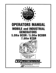
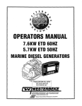
OPERATORS MANUAL
.MOBILE and INDUSTRIAL
...GENERATORS .
I
.....
..
.
-
r
- -" •
,.
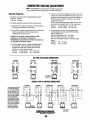
. 8.0KW BIOAR 10.0KW BIOAR
12.5KW BIOBR· ·15.0KW BIOCR
14.0
CR
.
.
REVISION 2
..--
WESTERBEKE CORPORATION '150 JOHN HANCOCK ROAD
MYLES STANDISH INDUSTRIAL PARK' TAUNTON MA 02780
WEBSITE: WWW.WESTERBEKE.COM
...,~~
NMMA Member National Marine Manufacturers Association
A WARNING
Exhaust gasses contain Carbon Monoxide, an odorless and
colorless gas. Carbon Monoxide is poisonous and can cause
unconsciousness and death. Symptoms of Carbon Monoxide
exposure can include:
-Dizziness
- Throbbing in Temples
-Nausea
- Muscular TWitching
-Headache
- Vomiting
- Weakness and Sleepiness -Inability to Think Coherently
IF YOU OR ANYONE ELSE EXPERIENCE ANY OF THESE SYMPTOMS,
GET OUT INTO THE FRESH AIR IMMEDIATELY. It symptoms persist,
seek medical attention. Shut down the unit and do not restart
until it has been inspected and repaired.
~W·
~!"!A!!'ii!!R~'"!!N~I!'!N~G~\,
,
"
, 'G!lneratots Prod~ QARSON MONOXIDE
Regular ~n!9nance Required
A WARNING DECAL is provided by
WESTERBEKE and should be fixed to a
bulkhead near your engine or generator.
WESTERBEKE also recommends installing
CARBON MONOXIDE DETECTORS. They are
,inexpensi~e and easily obtainable at your
local maflne or hardware store.
'j
i
1Fj=~~~
CALIFORNIA
PROPOSITION 65 WARNING
Marine diesel and gasoline engine
exhaust and some of its constituents
are known to the State of California
to cause cancer, birth defects,
and other reproductive Jtarm.
SAFETY INSTRUCTIONS
INTRODUCTION
•
Read this safety manual carefully. Most accUIents are
caused by failure to follow fundamental rules and
precautions. Know when dangerous conditions exist and
take the necessary precautions to protect yourself, your
personnel, and your machinery.
The following safety instructions are in compliance with
the American Boat and Yacht Council (ABYC) standards.
Do not operate with the air cleaner/silencer removed.
Backfire can cause severe injury or death.
• Do not smoke or permit flames or sparks to occur near
the fuel system. Keep the compartment and the
engine/generator clean and free of debris to minimize the
chances of fire. Wipe up all spilled fuel and engine oil.
• Be aware - diesel fuel will burn.
PREVENT BURNS - EXPLOSION
PREVENT ELECTRIC SHOCK
A WARNING: Explosions from fuel vapors can cause
injury or death!
A WARNING: 00 not touch AC electrical connections
•
while engine is running. Lethal voltage is present at
these connections!
•
Do not operate this machinery without electrical
enclosures and covers in place.
• Shut off electrical power before accessing electrical
equipment.
• Use insulated mats whenever working on electrical
equipment.
• Make sure your clothing and skin are dry, not damp
(particularly shoes) when handling electrical equipment.
• Remove wristwatch and all jewelry when working on
electrical equipment.
• Electrical shock results from handling a charged
capacitor. Discharge capacitor by shorting terminals
together.
PREVENT BURNS - HOT ENGINE
A WARNING: 00 not touch hot engine parts or
•
A WARNING: Accidental starting can cause injury
or death!
Always check the engine coolant level at the coolant
recovery tank.
A WARNING: Steam can cause injury or death!
•
•
•
•
ACCIDENTAL STARTING
exhaust system components. A running engine gets
very hot!
•
•
•
All fuel vapors are highly explosive. Use extreme care
when handling and storing fuels. Store fuel in a
well-ventilated area away from spark-producing
equipment and out of the reach of children.
Do not fill the fuel tank(s) while the engine is running.
Shut off the fuel service valve at the engine when servicing
the fuel system. Take care in catching any fuel that might
spill. DO NOT allow any smoking, open flames, or other
sources of fire near the fuel system or engine when
servicing. Ensure proper ventilation exists when servicing
the fuel system.
Do not alter or modify the fuel system.
Be sure all fuel supplies have a positive shutoff valve.
Be certain fuel line fittings are adequately tightened and
free oflealrs.
Make sure a fire extinguisher is installed nearby and is
properly maintained. Be faruiliar with its proper use.
Extinguishers rated ABC by the NFPA are appropriate
for all applications encountered in this environment.
In case of an engine overheat, allow the engine to cool
before touching the engine or checking the coolant.
PREVENT BURNS - FIRE
• To prevent accidental starting when servicing the
generator, remove the 8 amp fuse from the control panel.
• Disconnect the battery cables before servicing the engine/
generator. Remove the negative lead first and reconnect
it last.
• Make certain all personnel are clear of the engine before
starting.
• Make certain all covers, guards, and hatches are
re-installed before starting the engine.
A WARNING: Fire can cause injury or death!
•
Prevent flash fires. Do not smoke or permit flames or
sparks to occur near the carburetor, fuel line, filter, fuel
pump, or other potential sources of spilled fuel or fuel
vapors. Use a suitable container to catch all fuel when
removing the fuel line, carburetor, or fuel filters.
-..v WESTERBEKE
Engines & Generators
SAFETY INSTRUCTIONS
BATTERY EXPLOSION
A WARNING: Carbon monoxide (CO) is an invisible
A WARNING: Battery explosion can cause injury
odorless gas. Inhalation produces flu-like symptoms,
nausea or death!
or death!
•
Do not smoke or allow an open flame near the battery
being serviced. Lead acid batteries emit hydrogen, a
highly explosive gas, which can be ignited by electrical
arcing or by lit tobacco products. Shut off all electrical
equipment in the vicinity to prevent electrical arcing
during servicing.
• Never connect the negative (-) battery cable to the
positive (+) connection terminal of the starter solenoid.
Do not test the battery condition by shorting the terminals
together. Sparks could ignite battery gases or fuel vapors.
Ventilate any compartment containing batteries to prevent
accumulation of explosive gases. To avoid sparks, do not
disturb the battery charger connections while the battery
is being charged.
• Avoid contacting the terminals with tools, etc., to prevent
bums or sparks that could cause an explosion. Remove
wristwatch, rings, and any other jewelry before handling
the battery.
• Always tum the battery charger off before disconnecting
the battery connections. Remove the negative lead first
and reconnect it last when disconnecting the battery.
•
BATTERY ACID
•
Do not use copper tubing in diesel exhaust systems. Diesel
fumes can rapidly destroy copper tubing in exhaust
systems. Exhaust sulfur causes rapid deterioration of
copper tubing resulting in exhaust/water leakage.
• Do not install exhaust outlet where exhaust can be drawn
through vents, or air conditioners.
• Although diesel engine exhaust gases are not as toxic as
exhaust fumes from gasoline engines, carbon monoxide
gas is present in diesel exhaust fumes. Some of the
symptoms or signs of carbon monoxide inhalation or
poisoning are:
Vomiting
Muscular twitching
Dizziness
Intense headache
Throbbing in temples Weakness and sleepiness
AVOID MOVING PARTS
A WARNING: RotaUng parts can cause injury
or death!
Do not service the engine while it is running. If a
situation arises in which it is absolutely necessary to
make operating adjustments, use extreme care to avoid
touching moving parts and hot exhaust system
components.
• Do not wear loose clothing or jewelry when servicing
eqnipment; tie back long hair and avoid wearing loose
jackets, shirts, sleeves, rings, necklaces or bracelets that
could be caught in moving parts.
• Make sure all attaching hardware is properly tightened.
Keep protective shields and guards in their respective
places at all times.
• Do not check fluid levels or the drive belts tension while
the engine is operating.
A WARNING: Sulfuric acid in batteries can cause
severe injury or death!
•
When servicing the battery or checking the electrolyte
level, wear rubber gloves, a rubber apron, and eye
protection. Batteries contain sulfuric acid which is
destructive. If it comes in contact with your skin, wash it
off at once with water. Acid may splash on the skin or
into the eyes inadvertently when removing electrolyte
caps.
A WARNING: Carbon monoxide (CO) is a deadly gas!
•
•
•
HAZARDOUS NOISE
Ensure that the exhaust system is adequate to expel gases
discharged from the engine. Check the exhaust system
regularly for leaks and make sure the exhaust manifolds
are securely attached and no warping exists. Pay close
attention to the manifold and exhaust.
Be sure the unit and its surroundings are well ventilated.
In addition to routine inspection of the exhaust system,
install a carbon monoxide detector. Consult your dealer
for installation of approved detectors.
.
A WARNING: High noise levels can cause hearing
loss!
•
•
•
Never operate an engine without its muffler installed.
Do not run an engine with the air intake (silencer)
removed.
Do not run engines for long periods with their enclosures
open.
A WARNING: 00 not work on machinery when you are
mentally or physically incapacitated by tatigue!
...v'
WESTERBEKE
Engines & Generators
ii
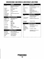
TABLE OF CONTENTS
Parts Identification .............................................2
Introduction .........................................................3
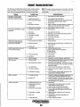
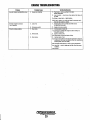
Engine Troubleshooting [Chart] ........................ 28
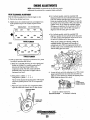
Engine Adjustme·nts ....... :...................................30
Warranty Procedures ........................................ .3
Serial Number Location .................................. .4
Diesel Fuel, Engine Oil, and Coolant .................5
Prestart Inspection ............................................ 7
Generator Voltage ............................................. 7
Valve Clearance Adjustment .......................... 30
Testing Engine Compression .......................... 31
Fuel Injectors ................................................. .31
Drive Belt Adjustment. ................................... 31
Control Panel Troubleshooting [Chart] ............. 32
Electronic Governor Adjustments .....................33
Description.... :............................................ :.... 33
Controller Adjustment .................................... 33
Inspect and Adjust .......................................... 33
Linear Actuator Troubleshooting [Chart] .......... 34
Starting/Stopping Procedure ............................... 8
GenRemote Calibration .....................................35
Generator Control Panels ....................................6
Description of Switches .................................... 6
Description of Gauges· ...................................... 6
Remote Panel .................................................... 6
Preparations for Initial Start-Up .........................7
Safety Shutdown Switches ............................... 9
GenRemote Control Station .............................36·
Generator Break-in Procedure ......................... .10
GenRemote Wiring Diagram ............................. .37
The Daily Operation .......................................... .11
GenRemote Installation Oiagram .....................38
Maintenance Schedule .................................... .12
Stop/Start Rocker Switch .............................. .38
Cooling System .................................................. 14
GenRe mote Specifications .............................. .39
Changing Coolant ........................................... 14
. Generator litformation .......................................40
Thermostat ........ :............................................. 15
Power Take Off Systems ................................... .41
Fuel System ....................................................... 16
BT Generator .....................................................42
Fuel FilterIWater Separator ............................ 16
BT Generator Wiring Schematic ...................... .43
Fuel Injection Pump ...................................... .16
Fuel Lift Pump ................................................ 16
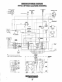
BT Generator Single Phase .............................. .44
Fuel Lift Pump Filter. .................................... .16
Generator Voltage Adjustment ........................ .45
Fuel Filter ....................................................... 16
BT Generator Voltage Regulator.. .....................47
Engine Fuel Filter ............. :............................. 16
BT Generator Internal Wiring .......................... .48
Engine Lubricating OiL .................................... 17
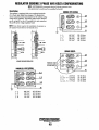
Regulator Sensing Wye-Delta Configurations .. 49
Engine Oil Change ......................................... 17
BT Generator Troubleshooting [Chart] ............ 50 .
Remote Oil Filter ...................................:........... 18
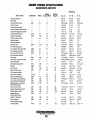
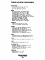
Specifications 1D.DKW/B.DKW BTOAR,_............ 51
Oil Pressure ....................................................... 19
Specifications 15KW/12.5KW BTOB R~............ 52
Testing Oil Pressure ........................................ 19
Generator Specifications 1D.DKW/B.oKW......... 53
DC Electrical System .........................................20
Alternator Troubleshooting ............................ 20
Generator Specifications 15KW BTOCR.......... .54
12 Volt DC Control Circuit ............................ 21
Generator Specifications 12.5KW BTOBR"........ .54
Battery Care .................................................... 21
Generator Specifications14,KW BTOC'R _..... 54A
Starter Motor .....................................................22
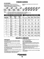
Engine Torque Specifications ...........................55
Troubleshooting .......................................... :... 22
Service ............................................................ 23
Standard Hardware ................................:.. ;........ 56
Sealants and Lubricants .................................. 56
Glow Plugs .........................................................24
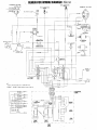
Generator Wiring Diagram #44744 .....................25 . Metric Conversion Data .................................... 57
Suggested Spare Parts ..................................... 58
Generator Wiring Schematic ~.. ~.~ ............ 25A
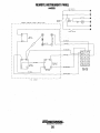
Remote Instrument Panel ................................26
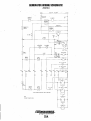
Generator Wiring Diagram #044927 ..................27
Generator WiringSchematic ...........................27A
Engines & Generators
1
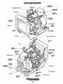
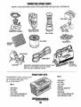
PARTS IDENTIFICATION
STOP SWITCH
AIR INTAKE/AIR FILTER
;REMOTE PANEL
CHARGING
ALTERNATOR
.~SSEMBLY
~~l----:;:;J~- START MOTOR
MOUNT
FRONT
• LEFT SIDE
OIL SUMP _ _ _ _ _ _~
~-i~OOLANT PRESSURE CAP
,RADIATOR
OIL FILL
EXHAUST
RIGHT SIDE
20A CIRCUIT
J---EN'''N. SERIAL
NUMBER
REAR
CONTROL PANEL
PUMP
BACKEND
PREHEAT
DRAIN HOSE
OIL FILTER.
LIFT PUMP
At
BREAKER
Engines & Generators
2
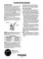
INTRODUCTION
This WESTERBEKE Diesel Generator is a product of
WESTERBEKE's long years of experience and advanced
technology. We take great pride in the superior durability and
dependable perfonnance of our engines and generators.
Thank you for selecting WESTERBEKE.
In order to get the full use and benefit from your generator it
is important that you operate and maintain it correctly. thIS
manual is designed to help you do this. Please, read this
manual carefully and observe all the safety precautions
throughout. Should your generator require servicing, contact
your nearest WESTERBEKE dealer for assistance.
This is your operators manual. A parts catalog is also
provided and a technical manual is available from your
WESTERBEKE dealer. If you are planning to install this
equipment contact your WESTERBEKE dealer for
WESTERBEKE'S installation manual.
WARRANTY PROCEDURES
Your WESTERBEKE Warranty is included in a separate
folder. If, after 60 days of submitting the Warranty Registry
fonn you have not received a customer identification card
registering your warranty, please contact the factory in
writing with model information, including the unit's serial
number and commission date.
PRODUCT SOFTWARE
Product software, (tech data, parts lists, manuals,
brochures and catalogs), provided from sources other than
WESTERBEKE are not within WESTERBEKE's control.
. WESTERBEKE CANNOT BE RESPONSIBLE FOR THE
CONTENT OF SUCH SOFTWARE, MAKES NO
WARRANTIES OR REPRESENTATIONS WITH RESPECT
THERETO, INCLUDING ACCURACY, TIMELINESS OR
COMPLETENESS THEREOF AND WILL IN NO EVENT
BE LIABLE FOR ANY TYPE OF DAMAGE OR INJURY
INCURRED IN CONNECTION WIlli OR ARISING OUT
OF THE FURNISHING OR USE OF SUCH SOFTWARE.
WESTERBEKE customers should also keep in mind the
time span between printings of WESTERBEKE product
. software and the unavoidable existence of earlier
WESTERBEKE manuals. In summation, product software
provided with WESTERBEKE products, whether from
WESTERBEKE or other suppliers, must not and cannot
be relied upon exclusively as the definitive authority on
the respective product. It not only makes good sense
but is imperative that appropriate representatives of
WESTERBEKE or the supplier in question be consulted
to determine the accuracy and currentness of the
product software being consulted by the customer.
Customer Identification Card
L~
NOTES, CAUTIONS AND WARNINGS
As this manual takes you through the operating procedures,
maintenance schedules, and troubleshooting of your marine
engine, critical infonnation will be highlighted by NOTES,
CAUTIONS, and WARNINGS. An explanation follows:
WESTERBEKE
J Engines & Generators
Customer Identification
MR. GENERATOR OWNER
MAIN STREET
HOMETOWN, USA
Model15BTDAR
Ser. #.
Expires 7120/2008
NDTE: An operating procedure essential to note.
A
CAUTION: Procedures, which if not strictly
observed, can result in the damage or destruction of
your engine.
A
WARNING: Procedures, which if not properly
followed, can result in personal injury or loss of life.
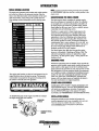
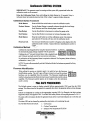
The WESTERBEKE engine serial number is an
alphanumeric number that can assist one in determining the
date of manufacture;A manufacturing date code is placed at
the end of the engine serial number. It consists of a character
followed by three numbers. Today it consists of two
characters. Previous date code. The character indicated the
decade E=2000s. The first number represented the year in
the decade, and the second and third, the month of that year.
Beginning in May 2008, the two characters HE. H
represented 2008 and the E the month of May and so on HF
2008 July, HG 2008 July.
Engines & Generators
3
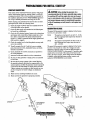
INTRODUCTION
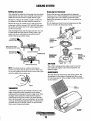
SERIAL NUMBER LOCATION
NOTE: A carbon monoxide warning decal has been provided
by WESTERBEKE. Affix this decal in a visible position in the
The engine and generator serial numbers and model numbers
are located on a decal on the generator housing. Take the
time to enter this information on the illustration of the narDeplate shown below, as this will provide a quick reference
when seeking techuical information and/or ordering repair
engine room.
UNDERSTANDING THE DIESEL ENGINE
The diesel engine closely resembles the gasoline engine,
since the mechanism is essentially the SarDe. The cylioders
are arranged above a closed crankcase;the crankshaft is of
the SarDe general type as that of a gasoline engine, and the
diesel engine has the SarDe type of valves, camshaft, pistons,
conoecting rods and lubricating system.
Therefore, to a great extent, a diesel engine requires the
same preventive maintepance as a gasoline engine. The
most important factors are proper ventilation and proper
maintenance of the fuel, lubricating and cooliog systems.
Replacement of fuel and lubricating filter elements at the
time periods specified is a must, and frequent checking for
contamination (that is water, sediment, etc.) in the fuel system is also essential. Another important factor is the use of
the SarDe brand of high detergent diesel lubrication oil
designed specifically for diesel engines.
The diesel engine does differ from the gasoline engine,
however, in its method of handling and firing of fuel. The
carburetor and iguition systems are replaced by a single
component - the fuel injection pump - which performs the
function of both.
Parts.~~~~~~~~~~,.~~~..
MOOEL _________
RPM ___________ _
KVV ____________ _
KVA ___________ _
VOLTS _________ _
AMPS _________ _
ENG, HP ______ _
ENG. SER. NO.
GEN. SER. NO.
PF/PHASE ___ _
VVIRES ________ _
RATING _______ _
INSUL CiJ\SS __
TEMP. RISE __ __
BATIERY ____ __
C.I.O. _________ _
ORDERING PARTS
Whenever replacement parts are needed, always provide the
generator model number, engine serial number, and generator
serial number as they appear on the silver and black narDeplate located on the generator end. You must provide us with
this information so we may properly identify your generator
set. In addition, include a complete part description and part
number for each part needed (see the separately furuished
Parts List). Insist upon WESTERBEKE packaged parts
because will fit or generic parts are frequently not made to
the SarDe specifications as original equipment.
The engine serial number can also be found staroped into the
engine block just above the injection pump. The generator
serial number is staroped into the generator housing on the
flat surface on the left side of the generator.
SPARES AND ACCESSORIES
Certain spares will be needed to support and maintain your
WESTERBEKE engine. Your local WESTERBEKE dealer
will assist you in preparing an inventory of spare parts.
See the SPARE PARTS page in this manual. For engine
accessories, see WESTERBEKE'S ACCESSORIES brochure.
An identification plate on the engine mauifold also displays
the engine model and serial number.
INSTALLATION MANUAL
Publication #43400 provides detailed information for
installing generators and a copy is supplied with each unit.
Also the manual is available from our website at
www.westerbeke.com to download in a pdf format.
GENERATOR
10 DECAL
ENGINE
SERIAL
NUMBER
--'GEIIERIITOR SERIAL
'NUMBER
Engines & Generators
4
DIESEL FUEL, ENGINE OIL AND ENGINE COOLANT
DIESEL FUEL
ENGINE COOLANT
Use fuel that meets the requirements or specification of Class
2-D (ASTM), and has a cetane rating of #45 or better.
WESTERBEKE recommends a mixture of 50% antifreeze
and 50% distilled water. Distilled water is free from the
chemicals that can corrode internal engine surfaces.
The antifreeze performs double duty. It allows the engine to
run at proper temperatures by transferring heat away from
the engine to the coolant, and lubricates and protects the
cooling circuit from rust and corrosion. Look for a good
quality antifreeze that contains Supplemental Cooling
Additives (SCAs) that keep the antifreeze chemically balanced, crucial to long term protection.
The distilled water and antifreeze should be premixed before
being poured into the cooling circuit.
Care Of The Fuel Supply
Use only clean diesel fuel! The clearance of the components
in your fuel injection pump is very critical; invisible dirt
particles which might pass through the filter can damage
these finely finished parts. It is important to buy clean fuel,
and keep it clean. The best fuel can be rendered
unsatisfactory by careless handling or improper storage
facilities. To assure that the fuel going into the tank for your
engine's daily use is clean and pure, the following practice is
advisable:
Purchase a well-known brand of fuel.
NOTE: Look for the new enviromnentallY1riendly long lasting
antifreeze that is now available.
ENGINE OIL
Antifreeze mixtures will protect against an unexpected freeze
and they are beneficial to the engine's cooling system. They
retard rust and add to the life of the circulating pump seal.
Use a heavy duty diesel oil with an API classification of
CF, CG-4, CH-4 or CI-4. Change the engine oil and filter
after an initial 50 hours of break-in operation. Then follow
the oil and filter change intervals as specified in the
MAINTENANCE SCHEDULE in this manual. Westerbeke
Corporation does not approve or disapprove of the use of
synthetic oils. If synthetic oils are used, engine break-in must
be performed using conventional oil. Oil change intervals
must be as listed in the MAINTENANCE SCHEDULE
section in this manual and not to be extended if synthetic oils
are used.
ANTIFREEZE PROTECTION
Antifreeze concentration
Freezing Temperature
A
Above 68'F (20'C)
SAE 30, 10W-30 or 15W-40
41'-68'F (5-20'C)
SAE 20, 10W-30 or 15W-40
Below 41'F (5'C)
SAE 10W-30 or 15W-40
14'F
(-5'C)
8'F
(-13'C)
35%
-4'F
(-20'C)
50%
-40'F
(-40'C)
A coolant recovery tank kit is supplied with each
WESTERBEKE diesel engine. The purpose of this recovery
tank is to allow for engine coolant expansion and contraction
during engine operation, without the loss of coolant and
without introducing air into the cooling system. This kit is
provided and must be installed before operating the engine.
For recommended oil viscosity, see the following chart·
Oil Viscosity
30%
COOLANT RECOVERY TANK
NOTE: The information above supersedes all previous statements regarding synthetic oil.
Operating Temperature
23%
NOTE: 7his tank, with its short run ofplastic hose, is best
located at or above the level of the engine~ manifold, but it
can be located below the level of the engine ~ manifold if the
particular ~nstallation makes this necessary.
CAUTION: 00 not allow two or more brands of
engine oil to mix. Each brand contains its own additives;
additives of different brands could react in the mixture
to produce properties harmful to your engine.
OIL PRESSURE
The engine's oil pressure, during operation, is indicated
by the oil pressure gauge on the instrument panel. During
normal operation, the oil pressure will range between 30 and
60 psi.
NOTE: A newly started, cold engine can have an oil pressure
reading upwards of 60 psi (4.2 kg/cm". A warmed engine can
have an oil pressure reading as low as 25 psi (1.8 kg/cm".
These readings will vary depending upon the temperature of
the engine, the load placed on the engine, and the RPM~.
Engines & Generators
5
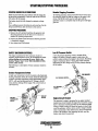
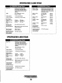
GENERATOR CONTROL PANELS
DESCRIPTION OF SWITCHES
This manualJy controlJed series of WES1ERBEKE marine
diesel generators is equipped with toggle switches on the
engine control panel and, optionally, at remote panels.
All three switches are momentary contact type and serve the
following functions:
EMERGENCY STOP: The EMERGENCY
stop switch on the side of the control box, '
is normally closed. When depressed, it
will open the DC circuit to the control
panel and shut the engine down. As the
switch is not toggled it can be used when
performing maintenance.
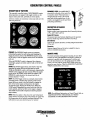
DESCRIPTION OF GAUGES
Coolant Temperature
Engine coolant (water) temperature should normally indicate
175' to 195' F (80' to 90' C).
Engine Oil Pressure
Oil pressure (psi) may fluctuate depending on the generator
load but should range between between 30 to 60 psi.
DC Voltmeter
Indicates the amount the battery is being charged should show
l3V to 14V.
Hourmeter
Registers elapsed time and is used as a guide for when to
perform scheduled maintenance.
PREHEAT: The PREHEAT toggle serves two purposes:
preheating the engine for easy starting and bypassing the
engine oil pressure switch. The PREHEAT function closes
the K2 relay. as well as supplies current to the fuel solenoid
pull coil.
.
When the PREHEAT switch is depressed, the voltmeter,
panel lights, gauges and meters and the hold coil of the fuel
solenoid.
START: The START toggle switch closes the KI relay that
energizes the starter solenoid and activates the starter.
While the PREHEAT switch is still depressed, depressing the
START switch engages the start solenoid. When the engine
begins to fire, the START switch should be released. The
PREHEAT switch should not be released until the oil
pressure reaches 5 - 10 psi.
STOP: The STOP toggle switch is a normally closed switch
providing power to the K2 relay. Opening of this switch
opens the power circuit to the fuel solenoid, stopping the
flow of fuel to the engine and shuts down the engine.
To stop the engine, depress the STOP switch. When the
STOP switch is depressed, the power feed to the fuel solenoid is opened, and the fuel flow to the engine is stopped.
The STOP switch should be depressed until the generator
stops rotating
REMOTE PANEL
For remote operation of the generator system, the same three
switches are used. The PREHEAT and START switches are
connected in parallel with the gauge panel's switches and
serve the same functions as in the gauge panei. The STOP
switch is in series with the gauge panel's STOP switch and
serves the same function. There is a REM01E START/STOP
WIRING DIAGRAM in this manual.
GENERATOR
RELEASE
STARTER
PREHEAT
~
PRESS Cf!))
MUST
1ST
e
f'li
STOP
START
I~~
\,fIiJ
PRESS
2 NO
WESTERBEKE
NOTE: For additional infonnation on Control Panels. Refer to:
STARTING/STOPPING PROCEDURE, DC WIRING
DIAGRAMS and TROUBLESHOOTING GAUGES.
NOTE: When the engine is shut down, the water temperature
gauge and the oil pressure gauge will continue to register the
last temperature and oil pressure readings displayed. They
will return to zero once-electrical power is restored.
Engines & Generators
6
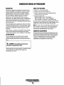
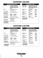
PREPARATIONS FOR INITIAL START-UP
PRESTARTINSPECTION
A CAUTION: When starting the generator, it is
This section of the manual provides the operator with preparation, initial starting, break-in, starting (warm or cold) and
stopping procedures. Follow the procedures as presented for
the conditions indicated and your WESTERBEKE generator
set will give reliable performance and long service life.
Before starting your generator set for the first time or after a
.prolonged layoff, check the following items:
Check the engine oil level. Add oil to maintain the level
at the high mark on the dipstick.
Check the fuel supply and examine the fuel filter/separator bowls for contaminants.
Check the DC electrical system. Inspect wire connections
and battery cable connections. Make certain the (+) battery cable is connected to the starter solenoid and the
negative (-) cable is connected to the engine ground stud
(this location is tagged).
Check the coolant level in both the plastic recovery tank
and at the manifold.
Visually examine the unit. Look for loose or missing
parts, disconnected wires, unattached hoses, and check
threaded connections.
Check load leads for correct connection as specified in
the wiring diagrams.
Examine air inlet and outlet for air flow obstructions.
Be sure no other generator or utility power is connected
to load lines.
Be sure that in power systems with a neutral line that
the neutral is properly grounded (or ungrounded) as the
system requires, and that the generator neutral is properly
connected to the load neutral. In single phase and some
3-phase systemS an incomplete or open neutral can supply the wrong line-to-neutral voltage on unbalanced
loads.
Make sure the mounting installation is secure.
Make sure that the generator is properly grounded.
recommended that all AC loads, especially large motors,
be switched OFF until the engine has come up tii speed
and, in cold climates, starts to warm up. This precaution
will preven{damage caused by unanticipated operation
of the AC machinery and will prevent a cold engine from
stalling.
o
o
o
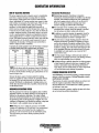
GENERATOR VOLTAGE
The speed of the generator engine is adjusted at the factory,
however, it is advisable to verify.
60 Hz
The engine no-load speed is set at 61.5 - 62 Hz.
At rated amperage hertz output may decrease to
48.6 - 59.0 Hz.
The engine no-load speed is set at 61.5 Hz. At
50Hz
rated amperage hertz output may decrease to
48.5 - 49.0 Hz.
The speed of the generator engine is adjusted at the factory,
however it is advisable to verify. The voltages are easily
adjusted to optimum values no-load and full load (refer to
VOLTAGE ADJUSTMENTin this manual). If possible, apply
actual service or test load of the same power factor as the
load to be used in service. If the voltage cannot be adjusted
to suitable values arid fault seems evident, contact your
authorized WESTERBEKE service dealer.
o
o
o
o
o
o
o
o
GLOW PLUG
CONNECTION
Oil Fill CAP
DIPSTICK
~
\l\>
~PPROXIMATELY
SIDE Oil
ONE QUART
Oil lEVEL
Y
-.rN'"
WESTERBEKE
Engines & Generators
7
CAP
STARTING/STOPPING PROCEDURE
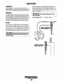
THE STARTING SYSTEM
Should tbe engine not start when tbe START switch is
depressed for 10 to 20 seconds, release botb switches and
wait 30 seconds; repeat tbe procedure above and preheat
longer. Never run the starter for more than 30 seconds.
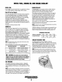
Westerbeke diesel generators use electric starters assisted by
glow plugs for botb normal and cold weatber starting. The
illustration below shows a cross-sectional view of one
cylinder. The glow plug is located in tbe combustion chamber so that its tip is in tbe injector nozzle's spray patb. When
tbe glow plug is energized by tbe PREHEAT button, the plug
glows red at !be tip and assists in igniting tbe fuel. The result
is a rapid start witb less wear on tbe starter.
This system is common to WESTERBEKE diesels. The start
circuitry is desigued so tbat tbe PREHEAT button must be
depressed for tbe time specified in tbe preheat chatt. Then,
while keeping tbe PREHEAT button engaged, tbe START
button is depressed to crank tbe engine.
Remote Starting Procedure
The remote statt panel is tbe same as tbe engine-mounted
start panel except tbat it has a green LED light and no
guages. When starting at a remote location, tbe green LED
lights when tbe generator is runrrlng at approximately 600
rpm. This indicates when tbe START switch can be released
since tbe starting of tbe generator may not be audible.
A. When tbe PREHEAT switch is depressed at tbe remote
start/stop panel tbe LED light will illuminate. When tbe
START switch is depressed and tbe starter cranks tbe
engine this LED light will dim. When tbe engine statts
tbe LED light will brighten sigualing to release tbe
START switch. Continue to hold tbe PREHEAT
depressed for a few seconds to allow oil pressure to build
up which closes tbe oil pressure safety switch that is in
tbe series patb for 12V B+ to tbe fuel run solenoid. The
green LED will remain brightly illuminated while tbe
engine is running.
B. After tbe generator is statted and tbe START switch is
released, tbe generator's starter will not crank uuless tbe
PREHEAT switch is operated first because tltis switch
supplies voltage to tbe START switch.
Once tbe engine statts, check tbe engine's insttnments for
proper oil pressure and battery charging voltage. Apply a
light load to tbe generator and allow tbe engine's operating
temperature to come up-to l40-lS0o P (60-66°C) before
applying heavy loads.
NOTE: The START switch will not energize unless the
PREHEAT switch is depressed. Depressing the PREHEAT
switch activates the glow plugs in the cylinder head so use
the PREHEAT intermittently to avoid overheating the glow
plugs.
GLOW
PREHEAT: Depress tbe PREHEAT switch. The volttneter and
panel lights, gauges and meters will be activated. The
PREHEAT switch shouW be depressed in accordance witb
tbe following chatt:
Temperature/Preheat
Almospherlc Temperalure
+41°F(+5°G) or higher
+41°F(+5°G) to 23°F (-5°G)
+23°F(-5°G) or lower
Limit 01 continuous use
NOTE: Some unstable running may occur in a cold engine.
Depressing the PREHEAT switch for 10-15 second intervals
will help stabilize the engine RPM until the operating
temperature reaches the 140-150°F and a load is applied to
the engine.
Preheallng Time
Approx. 10 seconds
Approx. 15 seconds
Approx. 20 seconds
30 seconds before cranking
START: While still depressing tbe PREHEAT switch, depress
tbe START switch. This will engage tbe starter solenoid.
Upon engine starting, release tbe START switch. Do not
release tbe PREHEAT switch until the oil pressure reaches
15 psi. Then as long as tbe high water temperature and low
oil pressure protective circuits do not activate, tbe engine will
remain energized and continue to run.
NOTE: When starting:
A voltage drop will occur
when the preheat switch
is depressed.
~
WESTERBEKE
Engines & Generators
8
STARTING/STOPPING PROCEDURE
STARTING UNDER COLD CONDITIONS
Remote Stopping Procedure
Make sure the lubricating oil conforms with the ratings for
the prevailiog temperatore. Check the table in the ENGINE
OIL section in this manual.
The battery should be fully charged to minimize voltage
drop.
Use a sufficient amount of preheat to aid in starting. See the
Temperature/Preheat chart elsewhere in this section.
To stop the generator, depress the STOP switch which opens
the normally closed B+ path for voltage to the engine's run
circuit. The STOP switch must be held open until the
generator comes to a complete stop and the green LED light
goes out.
STOPPING PROCEDURE
1. Remove the AC electrical load from the generator and
allow the generator to run for three to five minutes to
stabilize its operating temperatures.
2. Depress the STOP switch and hold it until the generator
is completely stopped.
3. Now release the STOP switch.
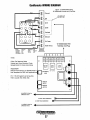
SAFETY SHUTDOWN SWITCHES
Low Oil Pressure Switch
The engine is protected by three automatic shutdown
switches. Should shutdown occur, do not ottempt to restart
wilhont finding and correcting the cause. Refer to the
heading ''Engine Stops" in the TROUBLESHOOTING
section of this manual.
The following is a description of these automatic shutdown
switches:
A low oil pressure shutdown switch is located off the
engine's oil gallery. Normally open in a static state, this
switch's sensor mouitors the engine's oil pressure. Should the
engine's oil pressure fall to 5-10 psi, this switch will open,
interrupting the DC voltage to the K2 relay, thereby shutting
off the engine.
Coolant Temperature Switch
A high water temperatore switch i.located on the thermostat
housing. Normal1y closed, this switch, should the fresh water
coolant's operating temperatore reach approximately 21O'F
(99'C), will open and intermpt the DC voltage to the K2
relay, thereby shutting off the engine. This switch resets at
195'F (107'C).
OIL PRESSURE .w""""
OIL PREilSUFIE-,L
SENOOR
COOLANT
TEMPERATURE
SWITCH
SENSOR
Engine Circuit Breaker
The generator's engine is protected by an engine mounted
manual reset circuit breaker (20 amps DC). Excessive current
draw or electrical overload anywhere in the instrument panel
wiring or engine wiring will cause the breaker to trip. In this
event the generator will shut down and the voltage to the K2
relay is terminated. If this should occur, check and repair the
source of the problem. After repairing the fault, reset the
breaker and restart the generator.
"'" WESTERBEKE
Engines & Generators
9
GENERATOR BREAK-IN PROCEDURE
DESCRIPTION
CHECK THE FOLLOWING
Although your engine has experienced a minimum of one
hour of test operations at the factory to make sure accurate
assembly procedures were followed and that the engine
operated properly, a break-in time is required. The service
life of your engine is dependent upon how the engine is
operated and serviced during its initial hours of use.
Breaking-in a new engine basically involves seating the
piston rings to the cylinder walls. Excessive oil consumption
and smoky operation indicate that the cylinder walls are
scored, which is caused by overloading the generator during
the break-in period.
Your new engine requires approximately 50 hours of initial
conditioning operation to break in each moving part in order
to maximize the performance and service life of the engine.
Perform this conditioning carefully, keeping in mind the
following:
Start the engine according to the STARTING PROCEDURE
section. Run the engine while checking that all systems
(water pump, oil pressure, battery charging) are functioning.
D Monitor the control panel gauges.
AFTER START-UP
Once the generator has been started, check for proper
operation and then encourage a fast warm-up. Run the
generator between 20% and 60% of full load for the first 10
hours.
D Check for leaks of fuel and engine oil.
D Check for abnormal noise such as knocking, friction,
vibration and blow-back sounds.
D Confirm exhaust smoke:
When the engine is cold - White Smoke.
When the engine is warm - almost Smokeless.
When the engine is overloaded - some Black Smoke.
To protect against unintentional overloading of the generator,
the generator's output leads should be routed through a circuit
breaker that is rated at the rated output of the generator.
NOTE: Be aware of motor staning loads and the high current
draw required for staning motors. This staning amperage
draw can be 3 to 5 times normal running amperage. See
GENERAIDR INFORMATION in this manual.
GENERATOR ADJUSTMENTS
Once the generator has been placed in operation, there may
be adjustments required for engine speed (hertz) during the
engine's break-in period (first 50 hours) or after this period.
A no-load voltage adjustment may also be required in
conjunction with the engine's speed adjustment. See
GENERATOR INFORMATION in this manual.
A
CAUTION: 00 not attempt to break-in your
generator by running without a load.
After the first 10 hours of the generator's operation, the load
can be increased to the full-load rated output, then
periodically vary the load.
""" WESTERBEKE
Engines & Generators
10
THE DAILY OPERATION
CHECK LIST
START THE GENERATOR
Follow this chdck list each day before starting your generator.
D Record the hourmeter reading in your log (engine hours
relate to the maintenance schedule.)
D Visually inspect the generator for fuel, oil, or water leaks.
D Check the oil level (dipstick).
D Check the coolant level in the coolant recovery
tanklradiator.
D Check your diesel fuel supply.
D Look for clean fuel in the fuel/separator transparent bowl.
D Check for loose wires at the alternator.
D Check the starting batteries (weekly).
D Check drive belts for wear and proper tension (weekly).
(See STARTING PROCEDURES on previous pages).
Allow the engine to warm up for 5 to 10 minutes to reach an
operating temperatures' of 140° to 150°F (60°-66°C) before
applying AC loads. Apply loads systematically allowing the
generator to adjust to each load before applying the next.
Check the gauges for proper oil pressure, operating
temperature, and DC voltage.
NOTE: Some unstable running may occur in a cold engine.
This condition should lessen as normal operating
temperature is reached and loads are applied.
A
CAUTION: Do not operate the generator for
.long periods of time without a load being placed
on the generator.
STOPPING THE GENERATOR
Remove the major AC loads from the generator one at a
time. Allow the generator to run for a few minutes to
stabilize the operating temperature and depress the stop
switch. (See STOPPING PROCEDURES on previous manuals).
~
WESTERBEKE
Engines & Generators
11
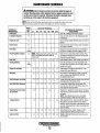
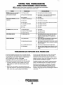
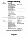
MAINTENANCE SCHEDULE
A WARNING: Never attempt to perform any service while the engine is
running. Wear,theproper safety equipment such as goggles and gloves, and
use the correct tools for each job. Disconnect the battery terminals when
servicing any of the engine's DC electrical equipment.
NOTE: Many of the following maintenance jobs are simple but others are more
difficult and may require the expert knowledge of a service mechanic.
SCHEDULED
MAINTENANCE
Fuel Supply
CHECK
EACH
DAY
HOURS OF OPERATION
50
100
250
500
750 1000 1250
EXPLANATION OF SCHEDULED
MAINTENANCE
Diesel No, 2 rating of 45 cetane or higher,
Fuel/Water Separator
0
0
Engine Oil Level
0
Oil level should indicate between MAX, and LOW on
dipstick,
Coolant Level
0
Check at recovery tank; if empty, check at manifold,
Add coolant if needed,
0
Inspect for proper tension (3/8" to 1/2" deflection)
and adjust if needed, Check bett edges for wear,
Drive Belts
Check for water and dirt in fuel (drain/replace filter
if necessary),
weekly
Visual Inspection of Engine
0
NOTE: Please keep engine surface clean. Dirt
and oil will inhibit the engine's ability to
remain cool,
Fuel Filler
Sfarting Batteries
0
0
0
0
0
0
Check for fuel, oil and water leaks, Inspect wiring
and electrical connections, Keep bolts & nuts tight
Check for loose belt tension,
Initial change at 50 hrs, then change every 250 hrs,
Every 50 operating hours check electrolyte levels
and make sure connections are very tight Clean off
excessive corrosion.
0
weekly
Engine Oil (and filter)
0
0
0
0
0
0
0
Initial engine oil & filter change at 50 hrs" then
change both every 100 hours.
Generator
0
0
0
0
0
0
0
Check that AC connections are clean and secure
with no chafing. See GENERATOR SECTION
for additional information,
Heat Exchanger Zinc Anode
0
0
0
0
0
0
0
Inspect zinc anode, replace if needed, clear the heat
exchanger end of zinc anode debris,
0
0
0
0
0
0
Inspect daily, Replace filter element every 250
hours of use or as found to be needed, Clean and
drain separator bowl as needed,
Fuel Filter/Water Separator
Electronic Governor Control
(if applicable)
Exhaust System
0
0
Engine Hoses
Inlet Fuel Filter
0
Check and or adjust the no·load speed in the panel,
required (hertz) and the regulator board adjustment
as needed.
NOTE: These adjustment are not a warrantable
adjustment during or after the unit's break-in.
0
0
0
0
Initial check at 50 hrs., then every 250 hrs, Ensure
the system is securely fastened to the exhaust
manifold. System is properly supported and muffler
and other components are in good serviceable condilion. No leaks,
0
0
0
0
0
0
Hose should be hard & tight Replace if soft or
spongy. Check and tighten all hose clamps.
0
0
0
0
0
0
Replace initially at 50 hours and then once a year
or as needed.
Engines & Generators
12
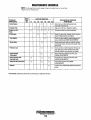
MAINTENANCE SCHEDULE
NOTE: Use the engine hour meter gauge to log your engine hours or record your
engine hours by running time.
SCHEDULED
MAINTENANCE
CHECK
EACH
DAY
HOURS OF OPERATION
50
100
250
Coolant System
750 1000 1250
0
Air Intake Filler
Electric FuelliH
Pump
500
0
0
DC Alternator
0
0
0
0
0
0
0
0
0
0
"Fuelln]ectors
EXPLANATION OF SCHEDULED
MAINTENANCE
0
Drain, flush, and refill cooling system with
appropriate antifreeze mix.
0
0
Clean every 100 hours. Replace as needed.
0
Check DC charge from alternator. Check mounting
bracket; tighten electrical connections.
Periodically check the wiring connections ..
Check and adjust injection opening pressure and
spray condition (see ENGINE ADJUSTMENTS).
0
"Starter Motor
0
0
Check solenoid and motor for corrosion. Remove
and lubricate. Clean and lubricate the starter motor
pinion drive.
"Preheat Circuit
0
0
Check operation of preheat solenoid. Remove and
clean glow plugs; check resistance (4-6 ohms).
Reinstall with anti-seize compound on threads.
"Engine Cylinder
Compression
0
0
Check compression pressure and timing (see
ENGINE ADJUSTMENTS).
"Torque Cylinder Head
Hold-down bolts
0
0
0
At first 50 hours, then every 500 hours (see
ENGINE ADJUSTMENTS).
"Adjust the Valve Clearances
0
0
0
Adjust Valve Clearances (see ENGINE
ADJUSTMENTS).
0
Remove, have professionally cleaned and pressure
tested.
"Radiator
"WESTERBEKE recommends this service be performed by an authorized mechanic.
Engines & Generators
13
COOLING SYSTEM
When the engine is started cold, external coolant flow is
prevented by the closed thermostat (although some coolant
flow is bypassed around the thermostat to prevent the engine
manifold from overheating). As the engine warms up, the
thermostat gradually opens, allowing full flow of the engine's
coolant to flow unrestricted to the external portion of the
cooling system.
DESCRIPTION
Westerbeke diesel engines are designed and equipped for
fresh water cooling. Heat produced in the engine by
combustion and friction is transferred to fresh water coolant
which circulates throughout the engine. This circulating fresh
water coolant cools the engine block and its internal moving
parts and the engine oil.
Fresh water coolant is pumped through the engine by a
circulating pump, absorbing heat from the engine. The
coolant then passes through the thermostat into the manifold,
to the radiator where it is cooled, and returned to the engine
block via the suction side of the circulating pump.
Coolant Recovery Tank
A coolant recovery tank allows for engine coolant expansion
and contraction during engine operation, without any
significant loss of coolant and without introducing air into
the cooling system. This tank should be located at or above
the engine manifold level and should be easily accessible.
FRESH WATER COOLING CIRCUIT
CHANGING COOLANT
NOTE: Refer to ENGINE COOLANT section/or the
The engine's coolant must be changed according to the
MAINTENANCE SCHEDULE. If the coolant is allowed to
become contaminated, it can lead to overheating problems.
r~commended antifreeze and water mixture to be used as the
fresh water coolant.
A CAUTION: Proper cooling system maintenance is
critical; a substantial number of engine failures can be
traced back to cooling system corrosion.
OIL
FILTER
,
\'
,.
Drain the engine coolant by loosening the drain plug on the
engine block and opening the radiator pressure cap. Flush the
system with fresh water, then start the refill process.
NOTE: The petcock on the radiator can also be used to drain
engine coolant.
A WARNING: Beware of the hot engine coolant•
•
\
Wear protective gloves.
COOLANT DRAIN'
~
WESTERBEKE
Engines & Generators
14
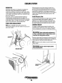
COOLING SYSTEM
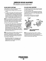
Refilling the Coolant
Replacing the Thermostat
After replacing the engine block drain plug, close the radiator
coolant petcock. then pour clean, premixed coolant into the
radiator and when the coolant is visible, start the engine.
Monitor the coolant in the radiator and add as needed. Fill
the radiator to the filler neck and install the pressure cap.
Remove the cap on the coolant recovery tank and fill with
coolant mix to halfway between LOW and MAX and replace
the cap. Run the engine, observe the coolant expansion flow
into the recovery tank.
After checking for leaks, stop the engine and allow it to cool.
Coolant should draw back into the cooling system as the
engine cools down. Add' coolant (0 the recovery tank if
needed. Clean up any spilled coolant.
Remove the cap screws and disassemble the thermostat
housing as shown. When installing the new thermostat and
gasket, apply a thin coat of sealant on both sides of the
gasket before pressing it into place. Do not over-tighten the
cap screws.
Run the engine and check for normal temperatures and that
there are no leaks at the thermostat housing.
,
TO GUULAN.r 1
RECOVERY
COOLANT
TEMPERATURE
SWITCH
BLEED
PETCOCK
MAKE CERTAIN THESE
PASSAGES ARE KEPT
THERMOSTAT
ASSEMBLY
SENDOR
[OPTIONALI
AIR FILTER
The air filter cartridge prevents engine room dust and dirt
from entering the engine, it also extends engine life, and
quiets the engine.
NOTE: Periodically check the condition o!the'radiator
pressure cap. Ensure that the upper and lower rubber seals
are in good condition and check that the vacuum valve opens
and closes tightly. Carry a spare cap.
MAINTENANCE
The filter should be cleaned every 100 operating hours. Tap
the cartridge on a flat surface to dislodge loose dirt or clean
off with compressed air. If the cartridge is badly contaminated
or oily, replace it.
THERMOSTAT
CARTRIDGE
A thermostat, located near the manifold at the front of the
engino, controls the coolant temperature as the coolant
continuously flows through the closed cooling circuit. When
the engine is first started, the closed thermostat prevents
coolant from flowing (some coolant is by-passed through a
hole in the thermostat to prevent overheating). As the engine
warms up, the thermostat gradually opens. The thermostat is
accessible and can be checked, cleaned, or replaced easily.
Carry a spare thermostat and gasket.
INTAKE
SILEN.CER
~
WESTERBEKE
Engines & Generators
15
FUEL SYSTEM
DIESEL FUEL
FUEL FILTERS
Use No.2 diesel fuel with a cetane rating of 45 or higher. Do
not use kerosene or home heating fuel.
The fuel injection pump and the fuel injectors are precisely
manufactured and they must receive clean diesel fuel, free
from water and dirt. To ensure this flow of clean fuel, the fuel
must pass through at least two fueLfilters, a fuel filter/water
separator and the engine's spin-on fuel filter. Visually inspect,
clean, and change these filters according to the maintenance
schedule in this manual.
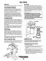
FUEL FILTERJWATER SEPARATOR
A primary fuel filter of the water separating type must be
installed between the fuel tank and the engine to remove
water and other contaminants from the fuel before they can
be carried to the fuel system on the engine.
The owner/operator is responsible for making certain the
fuel reaching the engine's injection equipment is free of
impurities. This process is accomplished by installing and
, maintaining a proper fuel filter/water separator betwen'the
, fuel tank and the generator/engine. Westerbeke recommends
a 10 micron filter be used.
A WARNING: Shut off the fuel valve at the tank
when servicing the fuel system. Take care in catching
any fuel that may spill. DO NOT allow any smoking,
open flames or othe~-sources of fire near the fuel
system whenservicin~. Ensure proper lientilation exists
when servicing the fuel system.
FUEL INJECTION PUMP
The fuel injection pump is a very important component of
the diesel engine, requiring the utmost care in handling. The
fuel injection pump has been thoroughly bench-tested and the
owner-operator is cautioned not to attempt to service it. If it
requires servicing, remove it and take it to an authorized fuel
injection pump service facility. Do not attempt to disassemble and repair it.
The only adjustment the servicing mechanic should make to
the fuel injection pump is the adjustment for engine idle
speed (see IDLE SPEED ADJUSTMENT under ENGINE
FUEL FILTER
O·RING
ADJUSTMENTS).
FUEL LIFT PUMP
Periodically check the fuel connections to and out of the
pump and make sure that no leakage is present and that the
fittings are tight and secure. The DC ground connection at
one of the pumps mounting bolts should be clean and well
secured by the mounting bolt to ensure proper pump operations.
When energized thru the preheat circuit, the fuel lift pump
will purge air from the fuel system and provide a continuous
flow of fuel as the engine is running.
FUEL LIFT PUMP INLET FILTER
ENGINE FUEL FILTER
To help ensure clean fuel to the lift pump, there is small inlet
filter connected to the fuel pump. This filter should be
replaced initially at 50 hours then once a year or as needed.
Periodically check the fuel connections and the bowl for
leakage. Replace the filter element after the first 50 hours
then follow the MAINTENANCE SCHEDULE.
Changing/cleaning the filter element
1. Shut off the fuel supply.
2. Unscrew the retainer ring that holds the filter bowl to the
housing and allow the bowl to come away from the
housing,
3. Remove and replace the filter element and clean the bowl.
4. Replace the sealing "0" ring and reassemble the bowl to
, the housing. Thread the retainer ting on carefully so as not
to cross thread. When retainer contacts the "0" ring,
tighten 114 - 1/2 tums by hand. Open the fuel supply and
run the engine to inspect for leaks.
~ngine~ ~ ~~nerators
16
ENGINE LUBRICATING OIL
LUBRICATlliN DIAGRAM
2. Replacing the 011 Fl1ter. When removing the used oil
filter, you may find it helpful and cleaner to punch a hole
in the upper and lower portion of the old filter to drain the
oil from it into a container before removing it. This helps
to lessen spillage. A small style automotive filter wrench
should be helpful in removing the old oil filter.
OIL PRESSURE
NOTE: Do not punch this hole without first loosening the
OIL PRESSURE ----..-"ffilfin,,;:;;..
SWITCH
filter to make certain it can be removed!
Place some paper towels and a plastic bag around the
filter when unscrewing it to catch any oil left in the filter.
(Oil or any other fluid on the engine reduces the engine's
cooling ability. Please keep your engine clean.) Inspect the
old oil filter as it is removed to make sure that the rubber
sealing gasket carne off with the old oil filter. If this
rubber sealing gasket remains sealed against the engine
block, gently remove it.
OIL
OIL DRAIN-----'
OIL SCREEN
NOTE: The engine oil is cooled by engine coolant
flowing through passages in the oil filter bracket
housing assembly.
/
OIL FILTER ASSEMBLY • .
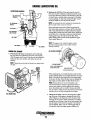
ENGINE OIL CHANGE
. (i
1. Draining the Oil Sump. Discharge the used oillhrough
the sump drain hose (attached to the front of the engine)
while the eugine is still warm. Drain the used oil completely.
replace the hose in its bracket. and replace the end cap
securely.
NOTE: Thread size fo,- the lube Qil drain hose capped end is
i/4 NPT.-
SEALING GASKET
..
APPLY CLEAN ENGINE OIL
WHEN INSTALLING
TURN ON HANO TIGHT
When installing the new oil filter element, wipe the filter
gasket's ·sealing surface on the engine block free of oil and
apply a thin coat of clean engine oil to the rubber gasket
on the new oil filter. Screw the filter onto the Ihreaded oil
filter nipple, and then tighten the filter finnly by hand.
NOTE: Generic filters are not recommended, as the
material standards o'r diameters of important items on
generic parts might be entirely different from genuine
parts. immediately after an oil filter change and oil fill,
run the engine to make sure the oil pressure is normal and
that there are no oil leaks around the new oil filter.
OIL DRAIN HOSE
3. Filling the Oil Sump. Add new oillhrough the oil filler
cap on the top of the engine or Ihrough the side oil filL
After refilling, run the engine for a few moments while
checking the oil pressure. Make sure there is no leakage
around the new oil filter or from the oil drain system, and
stop the engine. Then check the quantity of oil with the
lube oil dipstick. Fill to, but not over the high mark on
the dipstick, should the engine require additional oil.
Engines & Generators
17
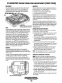
REMOTE OIL FILTER (OPTIONAL)
INSTALLATION
To install, 'llimply remove the engine oil filter and thread on
WESTERBEKE'S remote oil filter kit as shown. Always
install this kit with the oil filter facing down as illustrated.
This popular accessory is used to relocate the engine's oil filter from the engine.to a more convenient location such as an
engine room bulkhead.
Contact your WESTERBEKE dealer for more information.
NOTE: Westerbeke is not responsible for engine failure due to
incorrect installation of the Remote Oil Filter.
NOTE: Refer to ENGINE OIL CHANGE in this manual for
instructions on removing the oil filter.
A CAUTION: It is vital to install the oil lines
correctly. If the oil flows in the reverse direction, the
by-pass valve in the filter assembly will prevent the 011
from reaching the engine causing an internal engine
failure. If there is no oil pressure reading, shutdown
immedialetyand check the hose connections
APPLY A THIN COAT OF CLEAN OIL TO THE O·RING WHEN
INSTALLING THIS KIT. THREAD THE KIT ON, THEN HAND
TIGHTEN AN ADDITIONAL 3/4 TURN AFTER THE O-RING
CONTACTS THE BASE.
NOTE THE "IN" AND "OUT" MARKINGS
ON THE ADAPTER WHEN THE HOSES ARE
REMOVED FOR INSTAlLATION SO THEY
, WILL BE RECONNECTED CORRECTLY.
CONNECTION HOSE
·MUST ATTACH TO THE OUT
CONNECTION ATTHE
REMOTE OIL FILTER.
THE
HOSE
MUST ATTACH TO THE IN
CONNECTION AT THE
REMOTE OIL FILTER.
APPLY A
COAT OF CLEAN OlllO THEFILTER GASKET WHEN INSTAlLiNG. AFTER THE
FILTER CONTACTS THE BASE, TIGHTEN IT AN
ADDITIONAL 3/4 TURN •
...v: WESTERBEKE
Engines & Generators
18
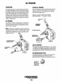
OIL PRESSURE
DESCRIPTION
TESTING OIL PRESSURE
To test the oil pressure, remove the oil pressure sender, then
install a mechanical oil pressure gauge in it's place. After
warming up the engine, set the engine speed at 1800 rpm
and read the oil pressure gauge.
The lubricating system is a pressure feeding system using
an oil pump. The engine oil is drawn from the oil sump by
the oil pump, which drives the oil, under pressure, through
the oil filter, oil cooler and various lubricating points in the
engine. The oil then returns to the oil sump to repeat the
continuous cycle. When the oil pressure exceeds the specified pressure, the oil pushes open the relief valve in the all
pump and returns to the oil sump, keeping the oil pressure
. within its specified range.
Oil Pressure 35.0 IbM (3.8 kg/em') or more at 1800 rpm.
Sender and Swlteh Torgue
9 ·13 ff-Ib (1.2 -1.8 m - kg).
FROM ENGINE
BLOCK
OIL PRESSURE
The engine's oil pressure, during operation, is indicated by
the oil pressure gauge on the instrument panel. During normal operation, the oil pressure will range between 30 and
60 psi (2.1 and 4.2 kg/cm').
NOTE: A newly started, cold engine can have an oil pressure
reading up to 60 psi (4.2 kg/em'). A warmed engine· can have
an oil pressure reading as low as 35 psi (2.5 kg!cm'). These
readings will vary depending upon the temperature ojthe
engine and the rpms.
TESTING DlL
PRESSURE
OIL PRESSURE
MECHANICAL OIL
PRESSURE GAUGE
OIL PRESSURE OWITrl•.
[NORMALLY OPENI
"
LOW OIL PRESSURE
The specified safe minimum oil pressure is 4.3 + 1.4 psi (0.3
+ 0.1 kgicm'). A gradual loss of oil pressure usually indicates
a worn bearings. For additional information on low oil pressure readings, see the ENGINE TROUBLESHOOTING chart .
OIL PREiISURE-,.,:':
SENDDR
.OIL PRESSURE RELIEF VALVE
An oil pressure relief valve is located on the engine block
just below the injection pump. 1bis valve opens at
appoximately 50 psi [343 kpa] and maintains that pressure.
LOCATED JUST
UNDER THE
. fUEL INJECTION
P[jMPONTHE
ENGINE BLOCK.
Engines &. Generators
19
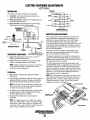
DC ELECTRICAL SYSTEM
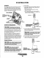
ALTERNATOR
The charging system consists of a DC belt driven alternator
with a voltage regulator, an engine DC wiring harness, a
mounted DC circuit breaker and a battery with connecting
cables. Because of the use of iutegrated circuits (IC's), the
electronic voltage regulator is very compact and is mounted
internally or on the back of the alternator.
50 AMP ALTERNATOR
1. Start the engine.
2. After the engine has rnn for a few minutes, measure the
starting battery voltage at the battery terminals using a
multimeter set on DC volts.
a. If the voltage is increasing toward 14 volts, the
alternator is working.
b.Ifthe voltage remains around 12 volts, a problem
exists with either the alternator or the charging circuit;
continue with Steps 3 through 8.
mID
#14 VIOLEET1~~;;~;~
TO FUEL S'
~~~;:.,
FUEL PUMP, AND
ill
TO T82111
~
MULTI METER
G
COM
TESTING THE STARliNG
BATTERYIALTERNATOR
(ENGINE RUNNING)
ALTERNATOR TROUBLESHOOTING
A WARNING: A failed alternator can become very
eI""
~
"<-
-L
-=
hot. 00 not touch until the alternator has cooled down.
gg9
g~~~
.J
STARTING BATTERY
GROUND
3. Thrn off the engine: Inspect all wiring and connections.
Ensure that the battery tenninals and the engine ground
connections are tight and clean.
Use this troubleshooting section to determine if a problem
exists with the charging circuit or with the alternator. If it is
detennined that the alternator or voltage regulator is faulty,
have a qualified technician check it.
The alternator charging circnit charges the starting battery
and any accessory battery. An isolator with a diode, a
solenoid or a battery selector switch is usually mounted in
the circnit to isolate the batteries so the starting battery is not
discharged along with the accessory battery. If the alternator
is charging the starting battery but not the accessory battery,
the problem is in the service battery's charging circuit and
not with the alternator.
A CAUTION: To avoid damage to the DC charging
alternator, never shut off the engine battery switch
when the engine is running!
4. Tum on the ignition switch, but do not start the engine.
5. Check the battery voltage. If the battery is in good
condition, the reading should be 12 to 13 volts.
~
0
Testing the Alternator
A CAUTION: Before starting the engine make certain
coM
+
MULTIMETER
that everyone is clear of moving parts! Keep away from
sheaves and belts during test procedures.
A WARNING: When testing with a multimeter;
TESTING THE
ALTERNATOR VOLTAGE
~
(IGNITION ON • ENGINE OFF )"1'" 999999
DC and AC circuits are often mixed together.
Always isolate DC and AC converters, and shut down the
engine before performing DC testing. No AC tests should
be made without a proper knowledge of AC circuits.
e
~r
'<".
, . WESTERBEKE
Engines &. Generators
20
-=-
GROUND
--~
...
~=']
~
STARTIN GBATTERY
DC ELECTRICAL SYSTEM
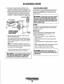
12 VOLT DC CONTROL CIRCUIT
6. Now check the voltage between the alternator output
tenninal (B+) and ground If the circuit is good. the volt·
age at the alternator will be the same as the battery, or if an
isolator is in the circuit the alternator voltage will be zero.
If neither of the above is Ime, a problem exists in the circuit betWeen the alternator and the battery. Check all the
connections -look for an opeuing in the charging circuit.
The engine has a 12 volt DC electrical control circuit that is
shown on the wiring diagrams that follow. Refer to these
diagrams when troubleshooting or When servicing the DC
electrical system.
A CAUTION: To avoid damage to the battery charging
e·.·'
MUlTI METER []bID
STARTING BATIERY
88 8
8 888
.
circuit, never shut off the engine battery switch while
the engine is running. Shut off the engine battery switch,
however, to avoid electrical shorts when working on the
engine's electrical circuit.
;~
~
COM
BATTERY
The ntiuimum recommended capacity of the battery used in
the engine's 12 volt DC control circuit is 600 - 900 Cold
Cranking Amps (CCA).
ALTERNATOR l'<1il-'I\\W~1
TESTING THE STARTING
BATTERY/ALTERNATOR
(ENGINE RUNNING)
Battery Care
..=--' ENGINE
GROUND
Review the manufacturer's reconnnendations and then
establish a systematic maintenance schedule for your
engine's starting batteries.
Monitor your voltmeter for proper charging during
engine operation.
Check the electrolyte level and specific gravity with a
hydrometer.
o Use only distilled water to bring electrolytes to a proper
level.
Make certain that battery. cable connections are clean and
tight to the battery posts (and to your engine).
Keep your batteries clean and free of corrosion.
7. Start the engine again. Check the voltage between the
alternator output and ground.
The voltage reading for a properly operating alternator
should be between 13.5 and 14.5 volts. If your altemator
is over· or under-charging, have it repaired at a reliable
service facility.
o
o
NOTE: Before removing the alternator for repair, use a
voltmeter to ensure that 12 volts DC excitation is present
o
o
at the EXC terminal if the previous test showed only battery voltage at the B output terminal.
If 12 volts is not present at the EXC terminal, trace the
wiring and look for breaks and poor connections.
A WARNING: Sulfuric acid in lead batteries can
cause severe burns on skin and damage clothing. Wear
protective gear.
A CAUTION: To avoid damaging the alternator diodes,
do not use a high voltage tester (i.e. a megger) when
performing tests on the alternator charging circuit.
-.v WESTERBEKE
Engines & Generators
21
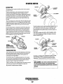
STARTER MOTOR
SOLENOID
DESCRIPTION
The starting system includes the battery, starter motor, solenoid,
and starter button.
When the starter button on the instrument panel is depressed,
current flows and energizes the starter's solenoid coil. The
energized coil becomes an electromagnet, which pulls the plunger
into the coil, and closes a set of contacts which allow high cunent
~ to reach the starter motor. At the same time, the plunger also'
serves to push that starter pinion to mesh with the teeth on the
flywheel.
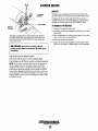
To prevent damage to the starter motor when the engine starts, the
pinion gear incorporates an over-running.Cone-way) clutch which
is spJined to the starter armature shaft. The rotation of the numing
engine may speed the rotation of the pinion but not the starter
motor itself.
Once the started button is released, tlle CUlTent flow ceases, stopping the activation of the solenoid. The.plunger is pulled out of
contact with tlle battery-to-start cables by a coil spring, and the
flow of electricity is interrupted to the starter. This weakens the .
magnetic fields and tlle starter ceases its rotation. As the solenoid
plunger is released, its movement also pulls the starter drive gear
fi·om its engagement with the engule flywheel.
')-:l~---(M) TERMINAL
IGNITION
TERMINAL
n
To test the ignition circuit, locate the ignition(s) terminal (it is one
ofthe smaIl tenninal studs and is wired to the ignition circuit).
Use a screwdriver, don't touch the blade, to imup from tlmt
ignition terminal to the positive battery cOllileetion tenninsl on
the solenoid.
If the starter cranks, the fault lies with the ignition circuit.
If the solenoid clicks but nothlng else happens, the starter
motor is probably faulty.
SOLENOID
SOLENOID.
MOTOR
POSITIVE
TYPICAL
STARTER MOTOR
').::~--'fll.nTERMINAL
REFER TO THE WIRING
DIAGRAM IN THIS MANUAL
IGNITION
TROUBLESHOOTING
Prior to testing, make certain the ships batteries are at full charge
and that the starting system wiring cOllilections (terminals) are
clean and tight. Pay particular attention to the ground wh'e
cmIDections on the engine block. .
To check the wiring, try cranking the starter for a few seconds,
never more than 10 seconds at a time, then nul your hand along
the wires and tenninals lookhlg for wann spots that indicate
resistance. Repair or replace any trouble spots.
Using a multimeter, test the voltage between the positive tem1inal
stud on the slalt solenoid and the engine block (ground).
If you read 12 volts, the starter is faulty.
~
If nothing at all happens the solenoid isn't getting current.
Check the battery isolation switch and inspect the wiring
collilections. It is also possible that the solenoid is defective.
A WARNING: There will be arching and sparks will
fly when jumping terminals. Be certain·the engine
space is treeot pofl!ntially explosive fumes, especially
gasoline.
Engines & Generators
22
STARTER MOTOR
SERVICE
Westerbeke uses a standard marine starter motor which can be
servieed or rebuilt at any starter motor automotive service center.
If replacing the starter motor, make certain the new motor is
eertified for marine use. Automotive starters do not meet USCG
standards. If in doubt, contant your WESTERBEKE dealer.
POSITIVE
~V_;o---~IM)
TERMINAL
TO REMOVE FOR SERVICE
IGNITION
TERMINAL
1. Disconnect the negative battery cable.
2. If necessary, remove any components to gain full access to the
starter motor.
3. Label and disconnect the wiring from the starter. (Do not allow
wires to touch, tape over the terminals).
4. Remove the starter mounting bolts.
5. Remove the starter from the engine. ill some cases the starter
will have to be turned to a different angle to clear obstructions.
Test again by jumping the two large terminal studs. Hold the
screwdriver blade firmly between the studs. Do not allow the
screwdriver blade to touch the solenoid or starter casing, this
would cause a short.
A WARNING: There will be arching as the full
starting current should be flowing thru the blade of the
screwdriver.
If the starter spins, the solenoid is faulty.
If the starter fails to spin, the motor is probably faulty.
If no arching occurred. There is no juice reaching the solenoid.
NOTE: Starter motors are either inertia type or pre-engaged. In
the pre-engaged model, the solenoid also moves an arm that
engages the starter motor to the flywheel of the engine. Using a
screwdriver to bypass the solenoid on such a starter will run the
motor without engaging the flywheel. Tum the starter switch on to
provide the power to the solenoid. Hopefolly it will create enough
magnetic field for the arm to move even though the contacts inside
the solenoid are bad.
-.y'
WESTERBEKE
Engines & Generators
23
GLOW PLUGS
DESCRIPTION
The glow plugs are wired through the preheat solenoid.
When PREHEAT is pressed at the control panel this solenoid
should "click" on and the glow plug should begin to get hot.
Re-install the plugs in the engine and test them again. The
plugs should get very hot (at the terminal end) within 7 to 15
seconds. If the plugs don't heat up quickly, check for a short
circuit. When reinstalling the glow plugs, use anti-seize compound on the threads.
INSPECTION
To inspect the plug, remove the electrical tenninal connections, then unscrew or unclamp each plug from the cylinder
head. Thoroughly clean each plug's tip and threads with a
soft brush and cleaning solution to remove all the carbon and
oil deposits. While clearring, examine the tip for wear and
bum erosion; if it has eroded too much, replace the plug.
A WARNING: Do not keep a glow plug on for more
than 30 seconds.
Glow Plug Tighlening Torque
7 -11 n-Ib (1.0 -1.5 m·kg)
TERMINAL
TESTING
END
An accurate way to test glow plugs is with an ohmmeter.
Touch one prod to the glow plug's wire connection, and the
other to the body of the glow plug, as shown. A good glow
plug will have a 0.4 - 0.6 ohm resistance. This method can be
used with the plug in or out of the engine. You can also use
an ammeter to test the power drain (5 - 6 amps per plug).
TESTING A GLOW PLUG
WITH AN OHMMETER
A WARNING: These glow plugs will become very hot·
TIP
to thB touch. Be careful not to burn your fingers when
testing the plugs.
TESTING A GLOW PLUG
USING A TEST LIGHT
+
Engines &' Generators
24
AL TERNATOR
\ GENERATOR ·WI_RING DIAGRAM '#44l44
""j
40A 24VDC
WAHR T'MPFRATUR'
AI TfRNATOR
WATER TEMPERATURE
lli!Qll
OM! ,LOI PlU~ pr~
=
~~
(" .. '"", ...
r-------------~--~--------------~~
BREMFR- 12vpe
~----~~~--_d--~~20~A~C~IR~C~U~'T~~--~~----_+--~~
/
BATTfRYSWITCH
I
~TER
Ol!
PRESSllRf
SENDER
,RF!
L!!:~ n)~L-",-",,,,,,,,u~.,,~,S2~I'U~ITIU----,
,
AUX. OIL PRESSURE
SWITCH
S~lm,
MOTOR
FUEL
1l[~11
,----~'''''~'"'~
.. -----+~ ~
p;'
;
~I
I'
""c,-
NOH:
I
R[IoIOV[ JU~PER WHEN CONNECTING A 5[COND REMOTE PANEL
2. GROUND 'I" T[RMINAl
or
PREHEAT SOLENOID ON Z4V SYSTE~ ONLY.
,-________-""'' ,,'' ' ' ' '·"1'__70 162 - I
IIIREDIWH1/
~--+----""'''C'''''''------0
m-2
;"~U'~'";:=j~ T51-3
TBI-5
I1--;=~"~'
m'~I!RD
iii REDIVIO
'9' '8' I (j).
~
-@ @-' l!.2!-
III III (
III OIIG
-l
I-
n
I
-3~('Si~'~"~·~":'"'~·:~~.,
11j)
01lV"
-<D -<D I @ Iii m "'lBI-IO
\V
SOA !2yO,
I
116 WHT
416
B~N
116 VIO
I
116 ORG
181-2
OIL
~I.
0sPR~SSURC
TB2-5
182-4
IS"---....±.
~I&
[O"5l
YEL
I~o'WATER
o [].--
i~\TEMP
PREHEAT
SWITCH
'---"V
REDIWHT
III 5t~
I
~/.
0-
@@@
;
L -______-'""."""''''''''-------016 2· B
<.::)
I
~
o cr--'
START
SWITCH
I
I
I
--'.0
HOUR
L
METER
VOL.T
METER
25
STOP
SWITCH
116 RED
-
I
I
GROUND TO
ENGINE
BLOCK
FUSE 8A
GENERATOR WIRING SCHEMATIC
#44744
r
BREAKER
1-;::"",
'-
-
r -
STIIRTER
--1
I STi>.RIER I
--'
ISOLE NO I 01
1
1
L ___ !
r
-<>:
GLOWPL UGS
r---l
1 EMERGENCY
1
-
1
1 ~I BATTERY
I SWITCH
1
CIRCUIT
.
.r-
BATTERY, 12-24VOC
:+
~~?~CH
I PREHEAT I
:SOLlNOI[):
L ___
T
1
AL TERNATOR
B
81
KI
START
T0
K2-RUN
81
30
TBI-I
".
CURRENT
..
WATER TEMP.
S~H
TI<ER ~
".J
OIL PRESS.
SWITCH
CD
FUEL SOL .
FU~
'</
r
b'1 510P
ISWITCH
1
I
1
PREHEAT
SWITCH
,
--
CD
11I40Q2
Tal·;
K2·RUN RELAY
T~'l
START
KI-START RELAY
86--(Yl-
L __ I
-'
e6~
FI HE AL,\R~
N.e. CONTACTS
REMOVE JUWPER
sw ITCH
~--?
1-;"-:
(OII~
HOll
AUX. nWITCH
'0'
OIL PRES~SEND[R
7
,
TSH
TBH
T62-1
Tal-S
TB1-2
T62-8
Ta2-S
TB2-'
WAf,Eft T~
SENOER
TBI-IO
,
il
1
5
l
I
,
•
,
(1
•
WATER TEMP.
GAUGE
~
r
1
I
I
:<,1
1
+
SWITCH
,
STA.RT
SWITCH
1-:::':',
.-~~
~
--?'"--
L __ I
IHD. LIGHT
OIL PRESS.
~
f----1 +
-T!PICAl
RE~OH
- >\--
tQj
STOP
PREHEAT
sw I TeH
S
START/STOP PANEL CO"(CTIONS-
~OTE.
S
GAUGE
- >\--
lc;j
VOLTMETER
OREMOTt: CONECTOR PINS
f----1 +
- >t--
to:J
-..v'
WESTERBEKE
Engines & Generators
L&
REMOTE INSTRUMENT PANEL
#44329
STOP SWITCH _
2
PREHEAT
SWITCH
3
~
0
START SWI TCH
-
-0
STOP
SWITCH
o{]o
o{]o
[~
u
<
5
m
r:::
~ 1122
RED
'-!'Y
I
I
\
ICl
.
N
N
G
.
-116 R[OfVL
,
1116 BLK
1116 RED/WHT
I
!
c:::,
If
II I 0 RED
/
c::::,
PREHEAT
SW ITCH
START
0
I
I
I
I
SWITCH
-
~
f1
~
111 ~ RED
I
I
I
I
I
I
I
I
1116 WHT
< ' - " - " - " _ . ' - " - " - " - ' . _ " - " - " - " - " - " - . _ .. _
P. N.
.. - .
44336
~
WESTERBEKE
Engines & Generators
26
~0C2
000
®@@
@@@
1116 WHT/REO
MALE CABLE
CONNECTOR
REAR VIEW
"illS YELfRED
I
I
r- ~(1)~
GENERATOR WIRING DIAGRAM
#044927 (OPTIONAL ELECTRONIC GOVERNING)
AI TERt/AIOR
II
AQA-?4VRC
~
-0--
"""
110 ORN
S~
~A
R
114 BRN
,~~
0
,!,I
WATER~RhTl!RF
~
d~
., •••• "'m,.,~
TtB!!~TQR
~n~-I~yt!!:
'r
r
.. - \~
" ..
'" "''"''
:.'
"
~
L."",,,.,, ' ' ' '.
I
I
~
"R:",
(
~ "'~""'
.,n
,"V~
B~rtKF~~~~~kc
"
H~:r
91' :dllii"Rf
ATT[RY SWI1<:H
r£o!---- ---~ <'
I
12-2~
J
VDC
L~
I
~
IS2.
j
AU~.
SHUfR "'OTOR
~
~-~
I
>r/~
I
""'-"""-
,
""'"''''' 'I
I
1
~
I
~,
I
I
I
-.!!'.
I
L
L
I
I
;";
::"'-:
."
I
~
~
~~
I
"',,,,,,,,-
~
Q
~
~
;:-----
"": '\
I CEI- 1
gj
=-'" 1""-"'-
I
~
,,[j
';:,
~
---ll'II
'
''''''
". ".
I
I
~OTE
:
I. RENOYE JUMPER WHEN CONNECTING A SECOND RENOT[ PANEL.
2. GROUND "'" TERMINAL Of PREHEAT SOl£MOIO ON 2~V SYSTEM onTo
..
." ., ,
..
"''''
'"
'" IHII~
III
ole
lB2·2
TOI-S
l~
DJ
I
I' - .. _ .. -., - .. - .. - .. -" -
T6~-1
'1Im,..,
j
O~G
'Ii ltL
PRESSURE
WAT<R
o
0., =-lHENT
,
TEMP
nl'~
." ..Hun
T61-2
~
!
-
-
•
TBl-l0
162-5
16l!'~
.
.
•
..,,"'" I.
STOP
:2)l82-8
HOUR
I..~.
VOLT
_
..
~e;~_
... Rro
.. _ .. _
Engines & -Generators
27
ENGINE
BLOCK
I-
I
~
GROliND 10
_
.. --.J
rUSE 8A
r
=rD,
GENERATOR WIRING SCHEMATIC
#044927 (OPTIONAL ELECTRONIC GOVERNING)
cr"·________
r
CIRCUIT
I
BR(AHR
"1
-"'~'~TITE~'~T_""c·!"~'~'£E
____________
BATTERY
I SWITCH
STARTER
~_~r",,,,,~_ _ _--,-C>---.r:..:j ,:::.L--l
L_.J
I STARTER I
,SOLENOID,
~------~-rlH-------------------~
GLOliPLUGS
r .., EMERGENCY
STOP
I
... -'I SWITCH
I PR£HEI.TI
ISOLINOI~
,------+---------Hh~------------~
AL HRNATOR
Kl·RUN
30
81
fUEL PUMP
I---------{
..
.r
r
I
WATER TEMP,
SWITCH
SlOP
ISWI1CH
+-__________
PREHEAT
SWITCH
+-~r~-~~'r-~
[_
Oil PRESS.
SWITCH
Kl-RUN UlAT
~--------~--+_------~.~"
START
SWITCH
.r
.r
HI-STARr RUAV
____~~r~-'~l~e__~_________________'~'
L _ J
AUX. C.P. SIIT(H
OIL PRUS. UND<R
TBI·2
TSH
162·2
WAHR iEMP. GAUGE
r..,
I
IND. tiGHT
OIL PRESS. GAUGE
-TYPICAL RENOH STARI/STOP PAHEL COH((1I0HS-
NOH:
VOL TMEHR
o REI«lH CO~£CTOR PINS
HOURMEl£R
~
WESTERBEKE
. E'!gines & Generators
27,A
ENGINE TROUBLESHOOTING
Note: The engine's electrical system is protected by a 20 amp
The following troubleshooting table describes certain problems
relating to engine service, the probable causes of these problems. aud the reconnnendations to overcome these problems.
Problem
Key switch on, PREHEAT switch
depressed: n.o panel indications;
fuel solenoid or electrical fuel pump
manual reset circuit breaker located on a bracket at the rear
of the engine.
Verilicalion}Remedy
Probable Cause
1. Battery Switch not on.
1. Check switch and/or battery connections.
2. Emergency stop switch off.
3. 20-Amp circuit breaker tripped.
2. Check emergency stop switch position.
3. Reset breaker; if breaker trips again, check preheat solenoid
Circuit and check circuit for shorts t.o ground.
4. Check K2 relay.
5. Check (+) connection to starter solenoid and (-) connection to
engine ground stud. Check battery cable connections.
4. K2 relay
5. Loose battery connections.
START SWITCH DEPRESSED, no starter
6. Check solenoid "S" terminal for voltage.
6. Preheat solenoid not .operating.
1. Connection t.o solenoid faulty.
1. Check connection.
2. Faulty switch.
3. Faulty solenoid.
4. Loose battery connections.
2. Check switch with ohmmeter.
3. Check that 12 volts are present at the solenoid connection.
4. Check battery connections.
5. Low battery.
5. Check battery charge state.
engagement.
START switch is depressed; panel
indications OK; starter solenoid OK
fuel solenoid not functioning.
6. K1 relay.
6. Check K1 relay.
1. Poor connections to fuel solenoid.
1. Check connections.
2. Defective fuel solenoid.
2. Check that 12 volts are present at the (+) connection on the
fuel run solenoid.
Generator engine cranks, but does not
start, fuel solenoid energized.
Engine can't be stopped.
Battery runs down.
3. Current limiter.
3. Check limiter.
1. Faulty 1ueling system.
1. Check that fuel valves are open.
2. Preheat solenoid faulty.
1a. Switch to combine house and start batteries.
lb. Replace batteries.
le. Check fuel lift pump.
2. Check solenoid.
3. Low battery.
3. Replace batteries.
1. Faulty DC alternator.
1. Oil Pressure switch.
1. Remove Exc. connection at alternator, repair alternator.
1. Observe if gauges and panel lights are activated when engine
2. High resistance leak to ground.
2. Check wiring. Insert sensitive (0 - .25 amp) meter in battery
3. Low resistance leak.
lines. (Do not start engine.) Remove connections and replace
after short is located.
3. Check all wires for temperature rise to locate the fault.
is not running. Test the oil pressure switch.
Battery not charging
Generator engine stops.
4. Poor battery connections.
4. Check cable connections at battery for loose connections,
corrosion.
5. DC alternator not charging ..
5. Check connections, check belt tension, test alternator. See
DC ELECTRICAL SYSTEM/ALTERNATOR.
1. DC charge circuit faulty.
1. Perform D.C. voltage check of generator challling circuit. See
2. Alternator drive.
DC ELECTRICAL SYSTEM/ALTERNATOR in this manual.
2. Check drive belt tension. Alternator should turn 1reely. Check
for loose connections. Check output with voltmeter. Ensure 12
volts are present at the Exc. terminal.
1. Fuel feed pump strainer is dirty.
1. Clean strainer.
2. Switches and/or wiring loose
or disconnected.
3. Fuel starvation.
4. 20 Amp circuit breaker tripping.
2. Inspect wiring for short circuits and loose connections.
Inspect switches for proper operation.
3. Check fuel supply, 1uel valves, fuel feed strainer..
4. Check for high DC amperage draw during operation.
Ensure breaker is not overly sensitive to heat which would
cause tripping.
5. Check for blockage, collapsed hose, carbon buildup at
exhaust elbow.
6. Pump water from 1uel tank(s); change filters and
bleed fuel system.
7. Check air intake filter cartridge.
5. Exhaust system is restricted.
6. Water in fuel.
7. Air intake obstruction.
I~/WESTERBEKE
I Engines & Generators
28
ENGINE TROUBLESHOOTING
Problem
Generator engine overheats/shuts down.
VerilicalionJRemedy
Probable Causu
1. Thermostat - remove and test in hot water.
1. Coolant not circulating.
Replace thermoslat.
2. Loss of coolant - check hoses, hose clamps, drain plug, etc.
for leaks.
2c. Broken or loose bells - tighten/replace.
Generator engine shuts down,
Low oil pressure,
1. Loss of oil.
Exhaust smoking problems
1. Blue smoke.
2d. Air leak in system; run engine and open the pressure cap to
bleed air. Add coolant as needed.
1. Check dipstick, look for oil leaks at oil filter and at
oil drain hose connection.
2. Replace oil pressure switch.
1. Incorrect grade of engine oil.
1a. Crankcase is overfilled with engine oil (oil is blowing out
through the exhaust).
2. Oil pressure swilch.
2. Engine is running cold.
23. Faulty injector or incorrect injector timing.
3. Improper grade of fuel.
3a. Fuel burn incomplete due to high back pressure in exhaust or
2. White smoke.
3. Black smoke.
insufficient air for proper combustion (Check for restrictions in
exhaust system; check air intake.).
ab. Improperly timed injectors or -valves or poor compression.
3c, Lack of air - check air inlake and air filter. Check for proper
ventilation.
3d. Overload .
...
~
WESTERBEKE
Engines & Generators
29
ENGINE ADJUSTMENTS
NOTE: WESTERBEKE recommends that the following engine
adjustments be performed by a competent engine mechanic.
VALVE CLEARANCE ADJUSTMENT
d. For 3 cylinder models, rotate the crankshaft 240
degrees to position the next cylinder in the firing order
at its TOe position and adjust the cylinder valves.
Rotate the crankshaft another 240 degrees to place the
last cylinder in the firing order at TOe, then adjust the
cylinder valves. If you rotate the crankshaft another
240 degrees, it should put the #1 cylinder at TOe of
its compression stroke with the TOe marl again in
alignment with the timing gear case mark.
Make the following adjustments when the engine is cold.
1. Remove the cylinder head cover.
2. Slightly loosen the cylinder head bolts and retighten them
to the specified torque in the number sequence shown
below.
Tightening Torque
65 ± 41b·H (BB±"5 Nm)
04
(15
e. For 4 cylinder models, rotate the crankshaft 180
degrees to position the next cylinder in the firing order
. 'at its TOe position and adjust the valves and so on for
the next two cylinders in the firing order.
01
012
Oll
FOUR CYLINDER
When the #2 cylinders are adjusted, rotating the
crankshaft another 180 degrees will bring the #1
cylinder back to its TOe on compression stroke and
the TOe mark on the crankshaft pulley should line up
with the timing gear case mark.
FRONT
010
01
THREE CYLINDER
3. Find top dead center compression position for No.1 piston
by using the procedure that follows.
a. Rotate the crankshaft observing the valve opening and
closing on cylinder #1 to correctly position the #1
piston on the Top Dead Center (TOC) of its
compression stroke. The TOC mark o~the front
crankshaft pulley should then be aligned with the
timing gear case mark.
4. Loosen the lock nut for the adjusting screw. With a feeler
gauge inserted between the rocker ann and valve cap,
adjust the valve clearance by turning the adjusting screw.
Make certain to adjust all the valves.
b. Firing order 3 cylinder: I - 3 - 2
Firing order 4 cylinder: I - 3 - 4 - 2
---''£''''''''"'''''''~
Valves will be adjusted in the firing order of the engine
with each cylinder piston at TOC of its compression
stroke.
0.25mm
(0.009B INCHES)
INTAKE & EXHAUST
c. With the #1 piston at TOe of its compression stroke,
adjust the intake and exhaust valve for that cylinder.
INJECTION TIMING
~ARK(1T)
5.
l
~
?
Install the cylinder head cover.
Head Cover Bolt Torque
TIMING GEAR
CASE MARK
Engin'!s & Ge,!_l!rators
30
"
2 - 3 H-Ib (0.3 - 0.45 m-kg)
ENGINE ADJUSTMENTS
NOTE: WESTERBEKE recommends that the following engine
adjustments be perfonned by a competent engine mechanic. The
information below is provided to assist the mechanic.
TESTING ENGINE COMPRESSION
FUEL INJECTORS
Make certain Ihe oil level (dipstick) is at the correct level
and the air intake filter is clean. The battery and starter motor
must also be in good condition.
L Warm Ihe engine to normal operating temperaiure.
2. Move the control lever to a position for shutting off Ihe
fuel. (Disconnect the wires if a fuel shutdown solenoid
is used).
3. Remove all the glow plugs from Ihe engine and install
the compression gauge/adarter combination to Ihe
cylinder on which Ihe compression is to be measured.
In case of severe vibrations and detonation noise, have Ihe
injectors checked and overhauled by an au!horized fuel
injection service center. Poor fuel quality, contaminant's and
loss of positive fuel pressure to the injection pump can result
in injector faults. Since fuel injectors must be serviced in a
clean room environment, it is best to carry at least one extra
injector asa spare should a problem occur.
Before removing the old injector, clean the area around Ihe
base of Ihe injector to help prevent any rust or debris from
falling down into the injector hole. If Ihe injector will not lift
out easily and is held in by carbon build-up or the like, work
Ihe injector side-to-side wilh the aid of Ihe socket wrench to
free it, and then lift it out.
The injector seats in Ihe cylinder head on a copper sealing
washer. This washer should be removed wilh the injector and
replaced with a new washer when Ihe new injector is
installed.
'
INJECTOR TO CYLINDER HEAD TIGHTENiNG TORQUE
40 ±4 ft-Ib (5.5 ± 0.5 kgl-m)
TESTING ENGINE
COMPRESSION
PRESSURE
GAUGE
ADAPTER
DRIVE BELT ADJUSTMENTCFANBELT)
c·.... .'
~WPLUGHOlE
4. Crank the engine and allow Ihe gauge to reach a
maximum reading, Ihen record Ihat reading.
5. Rereat this process for each cylinder.
COMPRESSION PRESSURE 427 psi (30 Kgl/cm') at 290 rpm.
MAXIMUM PERMiSSIBLE DIFFERENCE BETWEEN CYLINDERS
42.7 psi (3.0 Kgl/cm~
NOTE: If the readings are below the limit, the engine needs
repair.
6. Re-instalilhe glow rlugs and reset the fuel shut-off to the
run rosition.
Proper inspection, service and maintenance of the drive belts
, is important for the efficient operation of your engine (see
, Drive Belts under MAINTENANCE SCHEDULE).
Drive belts must be prorerly tensioned. Loose drive belts will
not provide proper alternator charging and will eventnally
damage Ihe alternator. Drive belts that are too tight will pull
'the alternator out of alignment and/or cause Ihe alternator to
wear out prematnrely. Excessive drive belt tension can also
cause rapid wear of the belt and reduce the service life of the
fresh water pumps bearing. A slack belt or Ihe presence of oil
on the belt can cause belt slipping, resulting in high operating
temperatnres.
The drive belt is properly adjusted if Ihe belt can be deflected
no less Ihan 3/8 inch (lOmm) and no more Ihan 112 inch
(12mm) as the belt is depressed with Ihe Ihumb at the midpoint between the two pulleys on the longest span of the belt.
, A spare belt or belts should always be carried on board.
LOW COMPRESSION
A
When low compression is fonnd, determine the cause by
applying a small amount of oil in the cylinder thru the glow
plug hole. Allow Ihe oil to settle.
Install the pressure gauge and repeat the above test. If Ihe
compression reading rises dramatically, Ihe fault is with Ihe
rings.
If Ihe compression valve does uot rise, the problem is wilh
the valves.
A slight rise in compression would indicate a problem wilh
bolh the rings and Ihe valves.
drive belt's tension while the engine is in operation_
Adjustin~ Belt Tension
1. Loosen Ihe alternator adjusting strap bolt and Ihe base
2.
3.
4.
5:
~
WARNING: Never attempt to check or adjust the
mounting bolt.
With Ihe belt loose, inspect for wear, cracks and frayed
edges.
Pivot the alternator on the base mounting bolt to.the left
or right as required, to loosen or tighten.
Tighten the base mounting bolt and Ihe adjusting strap
bolt.
Run ,lhe engine for about 5 minutes, Ihen shut down and
recheck the belt tensions.
WESTERBEKE
Engines & Gene-,at~rs
3.1
CONTROL PANEL TROUBLESHOOTING
MANUAL STARTER DISCONNECT (TOGGLE SWITCHES)
NDTE: The engine control system is protected by a 20 amp manual reset circuit breaker
located on the engine as close as possible to the power source.
Problem
Probable Cause
PREHEAT depressed, no panel indications
fuel solenoid, electric fuel pump and
preheat solenoid not energized.
START SWITCH DEPRESSED, no starter
engagement.
NO IGNITION, cranks, does not start.
NOT CHARGING BATTERY
VerilicalionJRemedy
1. Oil Pressure switch.
1. Check switches and/or battery connections.
2. 20 amp circuit breaker tripped.
2. Reset breaker. If it opens again, check preheat solenoid
circuit and run circuit for shorts to ground.
3. K2 relay faulty.
3. Check relay.
1. Connection to solenoid faulty.
1. Check connection.
2. Faulty switch.
2. Check switch with ohmmeter.
3.. Faulty solenoid.
3. Check that 12 volts are present at the solenoid connection.
4. Loose battery connections.
4. Check battery connections.
5 Low battery.
5. Check battery charge state.
6. K1 relay.
6. Check relay.
1. Faulty fueling system.
1. Check for fuel.
2. Check for air in the fuel system.
2. Allow system to bleed.
3. Faulty fuel lift pump.
3. Replace fuel lift pump.
1. Faulty alternator drive.
1. Check the drive belt and its tension. Be sure the alternator
turns freely. Check for loose connections. Check the
output with a voltmeter. Ensure 12V are present at the
regulator terminal.
BATTERY RUNS DOWN
1. Oil pressure switch.
1. Observe if the gauges and panel lights are activated when the
2. High resistance leak to ground.
2. Check the wiring. Insert sensitive (0·.25 amp) meter in battery
lines (Do NOT start engine). Remove connections and replace
after short is located.
3. Low resistance leak to ground.
3. Check all wires for temperature rise to locate the fault.
4. Faulty alternator.
4. After a good battery charging, disconnect alternator at output.
If leakage stops. Remove alternator and bench test. Repair or
replace.
engine is not running. Test the oil pressure switch.
TROUBLESHOOTING WATER TEMPERATURE AND DlL PRESSURE GAUGES
If the gauge reading is other than what is normally indicated
If both of the above gauge tests are positive, the gauge is
by the gauge when the instrument panel is energized, the first
step is to check for 12 volts DC between the ignition (B+)
and the Negative (B-) terminals of the gauge.
Assuming that there is 12 volts as required, leave the
instrument panel energized and perform the following steps:
1. Disconnect the sender wire at the gauge and see if the
gauge reads zero, which is the normal reading for this
situation.
2. Remove the wire attached to the sender tenninal at the
gauge and connect it to ground. See if the gauge reads full
scale, which is the normal reading for this situation.
undoubtedly OK and the problem lies either with the
conductor from the sender to the gauge or with the sender.
If either of the above gauge tests are negative, the gauge is
probably defective and should be replaced.
Assuming the gauge is OK, check the conductor from the
sender to the sender terminal at the gauge for continuity.
Check that the engine block is connected to the ground.
Some starters have isolated ground tenninals and if the
battery is connected to the starter (both plus and minus
terminals), the ground side will not necessarily be connected
to the block.
"'" WESTERBEKE
E.I1JJ.ines &
32
Gener~~t?rs
ELECTRIC GOVERNOR ADJUSTMENTS
(OPTIONAL)
TO ElECTROHIC
CONTROLlER
DESCRIPTION
(Cn1"t411~
The system is composed of three basic components:
1. Controller. A solid state component mounted in the
control box on the generator..
'ro1l:IIJII!1I
IIDNlIlU
"
,
2. MPU (Speed Sensor). Installed on the bellhousing over
the flywheel ring gear teeth.
3. Linear Actuator. Threaded into the engine block just
behind and below the fuel iniection pump
TO Ili!HSD n
"
;t
(12 AND 24 VDC) Iri===ib.!"".-L~
"',.
4~
5
J
f"
BLAtKIWM
3
.;:,
6~
VIOLrT
.
,lIlom
TeODVtllHOIi
INSPECTION AND ADJUSTMENT
The system has two styles of electronic controllers. The
early version (black encapsulated components) with 2
adjustments, a speed potentiometer and a GAIN adjustment. This controller is NLA. The current electronic
controller (aluminum housing with components inside) has
two push pads for speed adjustment. One pad to increase
speed (INC) and one pad to decrease speed (DEC). It also
has the GAIN adjustment,
These two ,electronic controllers are illustrated on this
page. When you press the preheat button, DC voltage is
sent to the controller to function with.
The engine is started, the new controller will operate the
engine in the 800-1000 range. Adjust the engine speed by
depressing and holding the INC pad until the speed reaches
the desired rpm (hertz) as possible.
The GAIN adjustment has been discussed earlier under
CALIBRATION. Place an amperage load on the generator
and note its reaction to the load. If the system is slow to
react and maintain the set speed, adjust the GAIN slightly
higher. The electronic governor system will maintain a set
speed at + or - 0.5 hertz from no an1perage load to full
rated amperage load for the generator.
NOTE: When stopping the unit, the engine only goes to a low
idle and does not shut down fully, the actuator will need a
slight adjustment to provide complete stopping of the unit.
Thread the actuator in 114 tum- 112 tum until complete
stopping of the engine is obitai',!eq/)""
•
D,Orn
FLYWHEEL--.... ~ ,,-r=:: '!
TEETH
,VV\
-
"".
",,2
REFER TO WIRING DIAGRAM
SENSOR_
'
---
MAGNETIC PICK-UP
lllOlfT
,m
,~
TERMINAL BOARD TB·3
• PNI04960lf"
LOCKNur-- _
:~ro( 1 .
vlOm
(TOUHEAIlAC ru~TOR
•
CONTROLLER. 1-::::"--1--,----,
flUlACr
, I
~
12 VDc SUPPl....
rrliTp;;~ll
SENSOR
PNilD39172
CONTROLLER ADJUSTMENT
.
LINEAR ACTUATOR PN!303007 12'
-
-
, 'PN1I39745 24V
1. Speed. This adjustment is used to raise or lower the
engine's speed to the desired hertz.
2. Gain. This adjustment affects the reaction time of the
actuator to the generator/engine load changes.
NOTE: A high gain adjustment can induce an oscillating
of the actuator producing a hunting mode. In such
cases, lessen the gain adjustment.
Calibration
1. With no power to the governor, adjust the GAIN to
9:00 o'clock.
2. Start the engine and adjust the speed by either turning the
speed potentiometer clockwise or depress and hold the
INC (increase) pad until the desire speed is obtained.
NOTE: Controllers are factory adjusted to minimum rpm.
However. for safety, one should be capable of disabling
the engine if an overspeed should exist.
3. At no-load, tum the GAIN potentiometer clockwise until
the engine begins to hunt. if the engine does not hunt,
physically upset the governor linkage.
4. Tum the GAIN potentiometer counterclockwise
until stable.
NOTE: The controller operates on I2VDC. The voltage
range is ± 20% (9.6VDC I2VDC I4.4VDC). Ifvoltage
varies above or below these ranges, the controller will
not operate and the engine will run in an idle mode until
proper voltage is supplied to the controller.
-..y'
ADJUSTMENT
WESTERBEKE
Engines & Generators
33
LINEAR ACTUATOR TROUBLESHOOTING
Problem
Correct
Tesl/Check
System appears dead.
(No actuator movement)
Engine runs, but at idle speed
1. Check the battery voltage at the controlier terminal block
with the Preheat switch depressed.
2. If there is no signal or a weak signal from the
MPU, measure the AC voltage being produced by the
MPU while cranking the engine. Measure between the white
and black/white wire leads on the controller terminal strip.
While cranking the engine or it is funning at idle, the voltage
should be 2.0-3.0 volts AC.
NOTE: The AC input impedance of meter must be
5000 ohms/volts or greater.
NOTE: When making this test in diesel units, disable the
preheat solenoid by disconnecting the "S" terminal connection
so as not to damage the glow plugs.
3. Check the actuator with the Preheat switch depresssed
This provides DC voltage to the controller. Measure the
DC voltage between the actuator connections on the
controller block and the black DC (-) power connection
on the controller terminal block. Both connections should
have battery voltage +0.00 or -0.75 VDC.
a Purple lead to Black DC (-).
b. Purple lead/purple/white lead to Black DC (-).
1. Inspect the DC circuit back to the starting battery.
2. Check for damage to or improper adjustment of
magnetic pick-up. replace or re-adjust.
3. Low voltage (1.0-2.0 VDC) at either actuator connections.
b. Replace the controller if battery voltage is not present at
both the Purple leads.
NOTE: Continue this test (ONLY) if the baffery
voltage is not present.
c. The following checks are performed between the
connections at the actuator and the Black DC (-) connection
on the controller terminal block. This is to determine if there
is a break in the line between the controllers terminal block
connection and the actuator connections or the actuator
leads themselves.
1} Low voltage (1.0-2.0 VDC) at either actuator connections.
2) Battery voltage at both actuator connections.
3) Battery voltage at one actuator connection but
not at the second.
Actuator
1. Check the controller by removing the two. purple leads
one at a time that come from the actuator off the controller
terminal block. lift one actuator lead and depress the
prehea'Von switch. Reconnect and do the same with the second.
Unit hunts during operation.
1. Check for a shorted actuator lead. Replace the
controller because it should not cause the actuator
lever to go to full fuel when the engine is not running.
a. Replace controller.
b. Check resistance of actuator coil.
12 Volt 3.0 - 3.1 ohm
24 volt to.7 -10.8 ohm
a. Actuator does not retract (Diesel).
b. Shorted/open coil in actuator.
Actuator (removed)
1) Broken actuator lead, repair.
2) Broken actuator lead, repair or replace actuator.
3) Check actuator winding for open. Replace actuator.
1. Re-adjust the calibration.
1. Improper governor adjustment.
2. If actuator doesn't fully retract
2. Inadequate power supply voltage.
(then check the actuator leads.
a. Connect a DC voltmeter to Red (+) and Black (-) leads
If the voltage is less than specified, check for
at the controller terminal block.
loose or poor connections in the DC circuit back to
b. Disconnect both leads coming from actuator from
the battery, check the K2 relay and its connections.
controller terminal block.
c. Connect one lead from the actuator to the Red (+)
on the terminal block and the other actuator lead to
the Black (-)on the terminal block.
d. Momentarily energize the start switch. The actuator
should fullY retract as long as the switch is depressed.
Measure the DC voltage across the Red (+) and Black (-lleads
while J:,!erforming this test. DC voltage must be greater han 80%
of the DC voltage measured across the battery supply.
9.0 VDC minimum
30.0 VDC maximum
NOTE: Reconnect the actuator leads properly after completing this test.
e. MPU positioned marginally too far away from f~wheel
e. Check the position of the MPU.
teeth giving erratic AC input to controller.
f. Check resistance value 950 -1000 ohm
If problems continue to persist, contact your WESTERBEKE dealer for additional assistance.
~
WESTERBEKE
Engines & Generators
34
GenRemote CALIBRATION
NOTE: THIS DATA APPLIES ONLY TO
.THE OPTIONAL GenRemote CONTROLS
The unit consists of a Power Logic Module, Display Panel and six conductor shielded Display
Cable. The shielded cable links the display to the module and can be up to 300 feet long. Two
display panels can be daisy chained to one (I) module output. The module supports two display
cable outputs allowing for a total of four (4) displays per module. Total allowed cable length per
module, including both display cable outputs, is six-hundred (600') feet.
The logic module is powered directly from the generator's cranking battery and consumes less
than 70 milli amps (70/1000 of an amp) when the generator is idle. DC operating voltage can be
12 or 24 volts. The AC generator output can be 115V, 240V, 50/60 Hz, single phase (10) or
three (3 0) phase.
Generator and Engine Monitoring
.
1.
DC Voltage
2.
Oil Pressure
3.
Water Temperature
4.
AC Voltage
5.
AC Current
L-l
6.
AC Current
L-2
7.
Line Frequency
Hz
8.
Engine Hours
Up to 10,000 Hours
9.
Exhaust Over Temperature Alarm
GenRemote is designed to safely interface with the existing engine sensors. The
digital display is easily calibrated to match the readings of the manufacturer supplied
mechanical gauge package.
The GenRemote circuitry is isolated from the generators OEM electrical system. This
assures that GenRemote will not interfere with the manufacturers supplied gauge
package. Electrical isolation also allows normal generator operation should the GenRemote be accidentally disconnected from the generator.
Electlical HooJv..Up
Electrical hookup includes interconnecting with both the generators AC and DC systems .
. TheAC wires Required: The 115 volt Line One [L-l) is Black. Line Two [L-2) is White. The 220 volt
, Line -2 [L-2] isBlackwithaRedStripe. The 220 VAC Neutral connection is White and is Not connected
1 to the GenRemote.
j The 220 VAC Generator Neutral is the same as Green Ground wire. The 115/220 VAC Neutral [White
Color) is connected to the generator frame.
The DC Wire Harness Supplied Color Code as follows: Green is Ground, White is ESS [Emergency Stop
Switch), WhitelBlack is the Stop Switch, Black is Preheat, Orange is Oil Pressure, Red is Water
. Temperature, Yellow is the ExhaustHigh Temperature Alarm [marine applications ouly) andBlacklRed,
',is the Start Button.
, IMPORTANT! The ExhaustHigh Temp terminal is connected to the ESS terminal when it is not used.
!
""" WESTERBEKE
Engine!--,&' Generators
35
!
GenRemote CONTROL STATION
IMPORTANT! The generator must be running and the system fully operational before the
calibration mode can be accessed.
'
Enter the Calibration Mode: Press and holding the Mode Button for 10 seconds. Entry is
indicated when the hundreds place decimal of the 3-digit, 7-segment display turns on.
Calibration Button Functions
Mode Bntton:
Press and hold the mode button to enter the calibration mode.
Preheat Button:
Use the Preheat Button to manually advance through the AutoGauge
Scroll functions until the desired gauge is reached.
Stop Button:
Use the Stop Button to decrement or reduce the gauge value.
Start Burton:
Use the Start Button to increment or increase the gauge value.
Mode Button:
Press the mode button to exit the calibration mode. Not pressing
any button for 30 seconds will also exit the calibration mode.
Firmware I.D.
The firmware identification number will appearjn,the displaywhen the
calibration mode is exited. A typical firmware identification number is
"A15".
Calibration Method
~----
IB\ DI81.
Calibrate the AutoGaugeScroll by using the values derived from f81Bi8~=P.~~"t~~'~""
the mechanical gauge package supplied with the generator.
0
Calibrate the AC Volt and Current Meter with a standard Amp I. . (J
=. LI.
and Voltmeter normally carried by most service technicians.
No calibration of the Frequency Meter is required or allowed. The Frequency Meter is factory
calibrated to ± one (1) Hz.
NOTE: The unit will automatically exit the Calibration Mode ifno buttons are pressed for thirty
(30) seconds.
Firmware Identification
When calling for service or warranty repair it is useful to have the firmware
identificiU;ion number. The unit's age, software revision level and the systems
hardware can be identified from this number. The firmware idel).tjfication
numberis also placed on the 28 pin microprocessor locatedinthe control module
ass@mbly. The flrmware.number appears in the display when the calibration
,
mode is exited.
IB18101
O.
F"mw".IO
•
.
FAIL SAFE PROCEDURES
The fall:safe system is ~etup to display potential failUres approximateiy 10% lower than the OEM
settings. This allows time for the operator to manually shut down the generator before serious damage
occurs.
Failures are displayed by turning on the appropriate' warning LED. For Example, the high coolant
temperature alarm will appear at 195 0 F and the OEM safety switch will stop the generator at 210 0 F.
The alarm LED will remain lit after the generator shuts down to provide indication as to why the unit
stopped.
The alarm LED can be cleared by pressing the stop button or by restarting the unit.
The Fail-Safe Protocols include:
1 - Oil Pressure
2 - Coolant Temperature
'3 - Exhaust Over temperature KLIXON
-..v- WESTERBEKE
Engi~t!l!.
& Generators
36
GenRemote WIRING DIAGRAM
Figure - 20 Westerbel<e Wlnng
for Westerbel<e Harness and Plug As<iry.
Black
Ground
LAND BASED UNITS
UMP ESS TO EXH
.........
• ESS
Whlte/Red
/
STOP
START
0
0 0 0
0 0 0
--"
BlACK
GROUND
WHrrEJRED
STOP
ORANGE
OIL
VElLOW/REO START
R
PreHeat
........
'e
Exhaust
all Press
To Westerbeke Wire
Hamess and Plug
orange
Water Temp
RED/VIOlET ESS
WHITE
PREHEAT
YEllOW
H20
Gerllem"'"
TEHminalBbck
telmlnal$ 1 thru 8
OZH '10
Notes:
0
Follow The Required State,
Federal and Local Eleotrical Code
Requirements for Proper Wire Sizing.
H~
~,s
diS SS3 ON9
0 0 0 0 0 0 0 0
PRE·HEAT
RELAY
Important!
Neutral Connection to GenRe mote Is
Not Recuired for 220 Volt Applications
HX3
Accessory
Jack
a
EJ
RElAY
PCB-7HHI0C
For 115 Volt systems l2 Is Neutral,
this Is usually the white wire.
DISPLAY
JACK 1
DISPLAY
JACK 2
e
o
l2 OUfPUl'TO LOAD or
Dls1r1butlon Panel
l2 INPUT FROM GENERATOR
l T INPUT FROM GENERATOR
L1 OUTPUT TO LOAD or
Distribution Ponel
Engines _& Generators
37
GenRemote INSTALLATION DIAGRAM
Note:
GenRemote uses engine oil pressure
and AC vo[tage to recognize the
engine is runn[ng,
Without AC [nput the generator will run
and GenRemote will only monttor the
Baftery, Water Temp and Oil Pressure,
NoACread[ngs will be displayed and the
Run [ndicator will not turn on,
GenRemote
Electrical Box'
~
I
Westerbeke 8 Wire Harness & Plug
D
'-----'
~
~
IOO@i]
"'
l\i
lloutBlack
L20ut While
11 In Black
rul
-.l
m';\'hIla aT 115 IJOO Neulral
.
Westerbeke AC Output l1 & l2
12
Neutra[ Not Requ[red
for
220 Volt Applicat[ons
'---'
.
---
- ----
ToAC load
AC load can be connected
d[rectly to generator, however,
the II and l2 current readings
will not be avallab[e,
The AC signal MUST be wired
to GenRemote,
---
STOP/START-ROCKER SWITCH
The One illuminated Button Start I Stop Rocker Switch is provided for areas where remote start stop
functions are required and no space is available for the standard display panel.
Startthe generator by pressing andreJeasingtbe upperrocker once. The lamp will flicker rapidly while
the generator is starting, The indicator lamp will remain on and steady while the generator is rurming.
. Stop the generator by pressing and rel~asing the lower rocker once.
Trouble Indicator: The indicator lamp will flicker slowlywhile the generator is operating ifa service
problem is developing. Possible problems include, High Coolant WaterTempemture, Low Oil Pressure
and High Exhaust Temperature Safety Switch.
Press Once To start
START
Light Flashes llopidlyWhiIe
Ge[1erala Is Starling.
Ugh\: Remains On
Whne Generator Is
Operotng
Press Once to Stop
Slow Bltnllng Ugtt \\!hila
\ht! Genera!or ~ lllXlnlng
lndlcalm Service Problem
STOP
6 conductor Dcto Coble
Maximum Length 150 '
Accessory ....: -_ __
Display 2
Display 1
""" WESTERBEKE
En.g~l1es
& Generators
38
GenRemote SPECIFICATIONS'
DC OPERATING VOLTAGES .................................................................
12 OR 24 VDC
DC CURRENT REQUIREMENT--MoDULE .............................................................. 50 MA .
. DC CURRENT REQUIREMENT--DISPLAY .............................................................. 20 MA .
DC CURRENT EACH ADDITIONAL DiSPLAy ............................................................. 15 MA
120/240 VAC
PHASE ................................................................................................... 10 OR 3 0
STANDARD CURRENT METER .......................................................................... 60 AMPS
REMOTE CURRENT METER ........................................................................... 200 AMPS
AC VOLTAGES .................................................................................
START RELAY ................................................................................................. 7 AMPS
STOP RELAY ...................; .............................................................................. 7 AMPS
PREHEAT RELAY ............................................................................................. 7 AMPS
MAXIMUM
MAXIMUM
# OF DISPLAYS
# OF DISPLAYS
PER MODULE ..................................................................... 4
DAISY CHAINED ................................................................. 2
MAXIMUM DISPLAY CABLE LENGTH (ONE DIRECTION) .......................................... 300 FT.
TOTAL ALLOWED DISPLAY CABLE LENGTH ........................................................
TEMPERATURE RANGE ............................................................. 0
0
600 FT.
F THROUGH 180 0 F
NOTE: Each module will support a maximum OffOUT displays. No more than two (2) displays
should be daisy chained to one module output. The module supports two (2) separate display
output lines.
""" WESTERBEKE
Eng/lle.1!
~
39
Generators
GENERATOR INFORMATION
USE OF ELECTRIC MOTORS
Generator Maintenance
The power required to start an electric motor is considerably
more than is required to keep it running after it is started.
Some motors require much more current to start them than
others. Split-phase (AC) motors require more current to start,
under similar circumstances, than other types. They are commonly used on easy-starting loads, such as washing
machines, or where loads are applied after the motor is
started, such as small power tools. Because they require 5 to
7 times as much current to start as to run, their use should be
avoided, whenever possible, if the electric motor is to be driven by a small generator. Capacitor and repulsion-induction
motors require from 2 to 4 times as much current to start as
to run. The current required to start any motor varies with the
load connected to it. Au electric motor connected to an air
compressor, for example, will require more current than a
motor to which no load is connected.
In general, the current required to start 115-Volt motors connected
to medium starting loads will be approxiruately as follows:
• Maintaining reasonable cleanliness is irnportaut.
Connections of terminal boards and rectifiers may become
corroded, and insulation surfaces may start conducting if
salts, dust, engine exhaust, carbon, etc. are allowed to
build up. Clogged ventilation openings may cause
excessive heating and reduced life of windings.
• For unusually severe conditions, thin rust-inhibiting
petroleum-base coatings, should be sprayed or brushed
over all surfaces to reduce rusting and corrosion.
• In addition to periodic cleaning, the generator should be
inspected for tightness of all connections, evidence of
overheated terminals and loose or daruaged wires.
• The drive discs on single bearing generators should be
checked periodically if possible for tightness of screws
and for any evidence of incipient cracking failure. Discs
should not be allowed to become rusty because rust may
accelerate cracking. The bolts which fasten the drive disc
to the generator shaft must be hardened steel SAE grade
8, identified by 6 radial marks, one at each of the 6
comers of the head..
• The rear armature bearing is lubricated and sealed; no
maintenance is required. However, if the bearing becomes
noisy or rough-sounding, have it replaced.
• Examine bearing at periodic intervals. No side movement
of shaft should be detected when force is applied.lf side
motion is detectable, inspect the bearing and shaft for
wear. Repair must be made qnickly or major components
will rub and cause major damage to generator.
MOTOR SIZE
(HP)
AMPS FOR
RUNNING
(AMPERES)
(~TARTING
1/6
114
113
1/2
314
1
3.2
4.6
5.2
7.2
10.2
13
6.4 to 22.4'
9.2 to 32.2'
10.4 to 72.S'
14.4 to 29.2'
20.4 to 40.S'
26 to 52
AMPS FOR
AMPERES)
"NOTE: In the above table the maximum Amps for Starting is
more for some small motors than for larger ones. The reason
for this is that the hardest starting types (split-phase) are not
mode in larger sizes.
CARBON MONOXIDE DETECTOR
WESTERBEKE recommends mounting a carbon monoxide
detector in the living quarters. Carbon Monoxide, even in
small amounts is deadly.
The presence of carbon monoxide indicates an exhaust leak
from the engine or generator or from the exhaust
elbow/exhaust hose, or that fumes from a nearby generator
are leaking in your area.
If carbon monoxide is present, ventilate the area with clean
air and correct the problem immediately!
Because the heavy surge of current needed for starting
motors is required for only an instant, the generator will not
be daruaged if it can bring the motor up to speed in a few
seconds. If difficulty is experienced in starting motors, tum
off all other electrical loads and, if possible, reduce the load
on the electric motor.
REQUIRED OPERATING SPEED
Run the generator first with no load applied, then at half the
generators capacity, and finally loaded to its full capacity as
indicted on the generators data plate. The output voltage
should be checked periodically to ensure proper operation of
the generating plant and the appliances it supplies. If an AC
voltmeter or arupmeter is not installed to monitor voltage and
load, check it with a portable meter and arup probe.
NOTE: When the area in which the generator is installed
contains AC equipment of 120 volts only, it is recommended
that the generators AC terminal block be configured to
provide one 120 volt AC hot leg for the distribution panel.
This will ensure good motor starting response from the
generator.
Englnes & .Generators
40
POWER TAKE OFF SYSTEMS
GENERATOR
END
POWER TAKE OFF ADAPTER
A power take off adapter can be attached to the generator I
backend. This adapter allows access to the full Rower of the \
enwe for a variety of hydraulic and electrical accessories. \
Contact your WESTERBEKE COMMERCIAL GENERATOR
SUPPUER for additional infonnation.
POWER TAKE OFF ADAPTER
XRT POWER SYSTEM
The XRT power system combined with a Westerbeke
generator provides electrical and hydraulic power for
fire/emergency apparatus The system generates electrical
power for auxiliary lighting and provides continuous
operation of up to three extrication tools at the sarne time.
HYDRAULIC PUMP
(OWNER
SPECIFICATIONS
Components
System Availability
Dimensions
Dual stage continuous duty pump, stainless
high pressure fittings, three gallon reselVoir
with filter, pump enclosure with integral control
block assemblies.
5.000 psi phosphate ester fluid and mineral
fluid systems up to 10,500psi.
COMBI pump in shroud.
L:l0" x W:15" x H:14" x 42 Ib,
Reservoir: H: 12" x W: 12" x D: 6.5"
Open Center Valves:
L: 3.75" xW: 2.75" x H" 4.0."
For additional information, contact XRT POWER
SYSTEMS at www.xrtcombi.comorcall (800) 343-0480.
XRT POWER SYSTEMS
321ioga Way
Marblehead, MA 01945
XRT COMBI POWER SYSTEM
"""" WESTERBEKE
Engines & Generators
41
I
BT GENERATOR
This generator is a four-pole, brushIess, self-excited generator
which requires only the driving force of the engine to produce AC output. The copper and laminated iron in the exciter
stator are responsible for the self-exciting feature of this generator. The magnetic field produced causes an AC voltage to
be induced into the related exciter rotor windings during rotation. Diodes located in the exciter rotor rectify this voltage to
DC and supply it to the windings of the rotating field. This
.creates an electromagnetic field which rotates throngh the
windings of the main stator, inducing an AC voltage which is
supplied to a load A step down transformer is connected in
parallel to tl)e AC output of the main stator. An AC voltage is
produced in the auxiliary windings of the transformer and the
main stator and is, in tum, supplied to a full-wave bridge rectifier. The rectifier produces a DC voltage to further excite
the exciter stator windings, enabling the generator to produce
a rated AC output. An optional solid-state voltage regulator is
available to work in tandem with the transformer regulator to
produce a more stable AC output.
/ OIPTICINAL AVR
AVR
A circuit breaker is installed on all WESTERBEKE generators.'This circuit breaker will automatically disconnect generator power in case of an electrical overload. The circuit
breaker can be manually shut off when servicing the generator to ensure no power is coming into the boat.
'
NOTE: This circuit breaker is available as a WESTERBEKE
add-on kit for earlier model generations; contact your
WESTERBEKE dealer.
CIRCUIT BREAKER
PART NUMBERS
VOLTAGE
ADJUSTMENT
/,,<L',. "In SWITCH
/AUIJUSTINGSHIMS
/COMPO,UND TRANSFORMER
BT GENERATOR
SINGLE PHASE
[6 STUD]
COMPOUND
TRANSFORMER
AC TERMINAL BOARD
AC
TERMINAL
BOARD
(12 STUD)
BREAKER
BRIDGE
BT GENERATOR
SINGLE PHASE
[12 STUD]
-.yo
WESTERBEKE
Engines & Generators
42 .
BT GENERATOR I SINGLE PHASE [SIX STUDI
r-------------------l
00:
:* i
:I
A
B
+:
a
I
II
:I
a
4
:
,b
1
2
L_______________
I
c
D
~~~==t=====~====: \
_-+___
I
I
I
~_J
50 Hz TERMINAL
:·~rn~-7
A.v.R.
,,,,----,"""....""--4'--++-.,
I
\ YElLOW
I
... /
'7
OJ
'8
REDfWHtTE
BLUE {WHITe
{TO PIN #8TERM.
SLUE tWHITe
(TO HERTZNOI.TS BAR)
BLACK
YELLON
\6VI
(TO HERTZNOLTS SAR) ,
PLUG
aRlaEN
.s 60 Hz TERMINAL
W2
50cyc;
AVR
I"m
8
.2
-t~~i-~:jt-
YE" _ ..
'WH'"
(TO~EZECTOR SWITCH)
BLACK/WHITe
(TO BRIDGE RECTIFIER)
"'-"CK
INTERNAL WIRING SCHEMATIC (SIX STUD)
W/OPTIONAL VOLTAGE REGULATOR
A. EXCITER STATOR WINDINGS 1& 2
A-I and A - 2 Exciter Stator Windings
(Selector in COMP position)
D. COMPOUND TRANSFORMER
1. Compound Transfonner Windings
2. Compound Transfonner Windings
3. Compound Transfonner Auxiliary Windings
Resistance readings and voltage checks can be accessed
easily for the components in the exciter circuit A, G, C-3 and
D-3 by locating the color coded wires at the connection
points shown on the above schematic. When checking
winding resistance values be sure to lift both of the
component's electrical connections.
G. BRIDGE RECTIFIER
A.V.R.
Optional Automatic Voltage Regulator Plug (6 Prong).
B. EXCiTER ROTOR and FIELD
1. Auxiliary Windings (A - B - C)
2. Diodes (6)
.
. 3. Rotating Field Windings
4. Suppr\",sor
•
C. MAIN STATOR
1. Main Stator Windings
2. Main Stator Windings
3. Main Stator Auxiliary Windings
Engines & Generators
43
BT GENERATOR· SINGLE PHASE (12 STUD)
r-------..,
r-------,
:I 1: I ~
r - - - - -- -------...,
r-
-
I
I
I
I
I
I
1
A
B
I
I
I
~4
I
c
I
L I I
2
IL _____________
J
1
L
B
ORANGE
+
DC
GREEN
I
31
1
1
~
1>1-
-
C
1
~
D
I
4
i
I
I
3
f------- J
w
"""a:
z
1
•
2~
1
=?'~
I
aN
!I
I WHT/BLK
L~l-ll--I--~J·
.
I
WHT IGREEN •
0
AC BLACK
AC
I
! • ! 11111ijr--~1-~- ~.
~ :! • ! 3..
G
-K1-AC
I
I
YELLOW
2
A
7
8
L
B
•
L
o
C
K
@
S
T
U
D
-
INTERNAL WIRING DIAGRAM
A. EXCITER STATOR WINDINGS
Resistance Value 10.0 Ohms
, B. EXCITER ROTOR and FIELD
1. Auxiliary Wiudiugs (A - B - C)
2. Diodes (6)
3. Rotating Field Windiugs
4. Suppressor
C. MAIN STATOR
1. Main Stator Wmdiugs
2. Main Stator Windings
3. Main Stator Auxiliary Windiugs
D. COMPOUND TRANSFORMER
1. Compound Transformer Wiudiugs
2. Compound Transformer Windiugs
3. Compound Transformer Auxiliary Windings
G. BRIDGE RECTIFIER
OPTIONAL AUTOMATIC VOLTAGE REGULATOR (AVR)
BT 6 STUD MODELS ONLY
NOTE: The plug is keyed to engage the regulatorreceptacle in
one direction. Check this and insert it correctly.
3. Before moving the selector switch to the ELEC position,
the NO-Load voltage produced by the generator when in
the COMP position will have to be adjusted. The NOLoad voltage should be adjusted down between 114 - 118
volts (60Hz) or 224 - 228 volts (SOHz) following the
procedures as explained earlier in tbis manual.
An optional solid-state voltage regulator (board #34410)
is available for nse with the BT series generators. When
installed, and the regulation switch is moved to the ELEC
position, the regulator works together with the standard com. pound transfonner regulator to regulate the generator's voltage output. In the ELEC mode, the regulator provides
excitation to the group 1 exciter windings, and the transformer provides excitation to the group 2 exciter windings.
4. With the generators no load voltage properly adjusted,
move the selection switch iuto the ELEC position. Adjust
the regulator board potentiometer to set NO-Load voltage
at 120 - 122 volts at 61.S - 62.0 Hertz (230 - 234 volts at
SI.S - S2.0 Hertz). Tbe regulator board is operating in parallel with the compound transformer and should maintain
voltage output witbin ±5 per cent from NO-Load to
FULL-Load.
Installation
1. The regulator is mounted using existing tapped holes in
the generator's case. Use two (2) M4 x 0.7mm screws,
each ISmm long, with lock washers to mount the regulator board.
2. Connect the 6-prong generator plug to the receptacle on
'
the regulator board.
NOTE: Do not use the regulator to force NO-Load voltage
down. Use the compound transformer for this function. Using
the regulator to perform this causes the regulator to use more
exciter circuit power. This leaves less exciter circuit power
for loacled conditions.
""" WESTERBEKE
Engines & Generators
44
GENERATOR VOLTAGE ADJUSTMENT
NOTE: WESTERBEKE recommends tiull the following generator
tests and adjustments be performed by a quai/ijied technician.
Generator Frequency
d. After the no-load hertz adjustment is made, the no-load
voltage may need to be readjusted. In most cases, if the
generator was producing the correct no-load voltage at
the previous hertz setting, it would be correct at the
changed hertz setting.
In the event it needs adjustment, adjust the shim thickness under the laminated steel bar of the transformer.
60 hertz:
no-load voltage, 121-124 volts.
50 hertz: no-load voltage, 232-236 volts.
1. Frequency is a direct result of engine/generator speed:
1800 rpm = 60 hertz
1500 rpm = 50 hertz.
.2. To change generator frequency follow the steps below.
a. Connect the AC output leads to the AC tenninal block,
following the illustrations on this page.
e. Load the generator to the rated amperage output
b. If an AVR is installed, reposition the blue or blue/white
corresponding to the hertz speed of the generator,
Rated Loaded Speed
60 hertz: loaded speed, 58.5 - 59.0 heltZ
50 hertz: loaded speed, 48,5 - 49.0 hertz
The lowest acceptable voltage at full rated output
(amps)
60 hertz:
108 - 11 0 volts
50 hertz: 205 - 210 volts
lead to correspond to the hertz selected on the
VoltageiHertz Connection Bar.
If there is no automatic voltage regulator (AVR
installed, do uot change the wiring, on the
Voltage/Hertz Connection Bar. Simply reconfigure the
AC terminal for the hertz change.
c. Start the engine, monitor voltage and adjust engine
no-load speed. Adjust diesel units by the linkage
between the throttle arm and fuel solenoid or the
throttle lever on the injection pump ..
60 hertz:
no-load speed,
61.5 - 62.0 hertz.
50 hertz:
no-load speed,
51.5 - 52.0 heltZ.
SIX STUD AC VOLTAGE CONNECTIONS,
115V 50Hz
@
120V 60HZ
230V 50Hz
®
@
12D/240V 60HZ
®
N
A JUMPER IS
,!p=PEU--J
•
TWELVE STUD AC VOLTAGE CONNECTIONS
The frame ground Wlra must
be moved when changing
from 115 volts and 1101220
volts 50 hertz. to 230 volts
50 hertz. From making con·
nections to the AC tenninal
block. use !enninal ends for
1/4 inch studs that will
accept multl·strand copper
wire sized f0r the ampemge
rating from'the hot lead connection. The frame ground
wire is white or white with"a
115V 50Hz
230V 50Hz
=
=
0
0'
7
0
!l
"
,,'"~
~
t-
;z,
=
2
0
d::::1,
0
!l
120V 6D Hz
0
0
.3 07 !lin", ,,'
8.
N
b' • 0
10
0
1=0
0
0
=
7
12D/240V!6DHz
"'~ ,S
0
0
8
e,
0
=
7@:¢:PL2
6
0
~
<3
III
v
N
L\ ,2
N Ll
. green strip. It connects
between the neutral stud
and the generator frame.
.3
L1
115/230V 5DHz
0
•
CIRCUIT
BREAKER
II]
N
~1
r-
• •
Engines & Generators
45
~
"AREQUIRED
JUMPER IS
• •
GENERATOR VOLTAGE ADJUSTMENT
NOTE: WESTERBEKE recommends that the following generator
tests and adjustments be peifonned by a quailified technician.
NO-LOAD VOLTAGE ADJUSTMENT
FULL-LOAD VOLTAGE ADJUSTMENT
Voltage adjusttnent is made with the generator regulation
being governed by the compound transfOlmer.
1. The selector switch, if installed, must be in the COMP
position.
2. To confinn no-load voltage, start the generator and apply
a momentary (moderate) load to excite the transfOlmer.
The voltage produced by the generator after the momentary load is removed is no-load voltage. Note the voltage
output from the generators 120 volt leges) (230 volt 50
hertz). The no-load voltage should be between 121-124
volts at 61.5-62 hertz (232- 236 volts at 51.5-52 hertz).
NOTE: The no-load voltage should be adjusted to the voltage
The voltage hertz connection bar that is used when changing
from 60Hz to 50Hz can also be used to increase or decrease
the generators full-load output.
Fine voltage adjusttnents can be performed by repositioning
wires A to leads #1, #2, and #3 increasing the loaded voltage
progressively in that order. A no-load voltage adjusttnent will
have to be made as well.
Should full-load output fall below 108 volts-60Hz
(210 volts-50Hz), the voltage should be adjusted.
A TWO RED
WIRES
produced by the generator once started and a momentary
load should be applied to excite the transformer and then
removed. The voltage produced by the generator after this·
momentary load is removed is no-load voltage.
12 STUD
BLUE
WIRE '.
3. To raise or lower the voltage, shims of varying thickness
A BLUE
(non-conductive material) are placed or removed from
under the steel laminated bar on top of the compound
transformer. The material used for shimming should not
soften at temperatures in the 176' F (80' C) range. A
small reduction in no-load voltage (1 to 3 volts) can some
times be accomplished by gently tapping the top of the
laminated steel bar to reduce the gap between the existing
shims and the transfonner core.
WIRE
6 AND 12 STUD VOLTAGE HERTZ
CONNECTION BARS
NOTE: No-load voltage mny be effected needing readjustment
NOTE: When the optional voltage regulator is installed
and if the Blue!White (Blue) lead is not correctly positioned
to correspond to the Hertz the unit is operating at, the
regulator will sense incorrect voltage and cause the generator
to produce abnormally high output voltage.
with the compound transformer. Do not use these
adjustments to compensate for overload conditions being
placed on the generator/engine (inductive-motor type loads).
Loss of generator hertz/speed, the result of overload, will
cause a drop in voltage output.
Shim thickness of 0.001 inch will change the no-load
voltage by approximately 4 - 6 volts. Adding shim
material raises the no-load voltage. Removing shim
material lowers no-load voltage.
Engines & ,G~nerators
46
BT GENERATOR VOLTAGE REGULATOR ADJUSTMENTS [THREE PHASE]
Description
Amp-Hertz
The voltage regulator is an advanced desigu which ensures
optimum AC generator performance. It is equipped with
complete protection circuitry to guard against operating
conditions that could be detrimental to the AC generator:
VOLTAGE IIttil~LIII
Volts
These two adjustments are used in conjunction with the two
protection circuits in the voltage regulator that are indicated
by the illumination of colored LED lights.
1. Delayed overload protection (yellow LED).
2. Low speed protection (red LED).
Both systems have an intervention threshold which can be
adjusted using the respective potentiometer. Each of the two
circuits are able to cause an adequate reduction in excitor
voltage to safeguard the excitor windings and prevent their
overheating.
.
The overload protection system has a delay which permits
temporary overloading of the generator during times such as
motor start-up or other similar load surge demands. The regulator also has a third LED (green), that glows during generaPROTECTS THE REGULATOR BOARD tor operation to indicate correct operation of the regulator
FROM AN ELECTRICAL OVERLOAD
with the generator.
Setting the Overload Protection
This potentiometer is used to adjust output voltage. At proper
engine operating speed the output voltage should be held at
±1 % from a no-load condition to a full rated generator output
and from power factor 1.0 - 0.8 with engine drive speed
variations up to -6%. Prior to starting the engine, turn the
VOLT and STAB trinuners (using a mini phillips screwdriver) fully in a counter clockwise (Minimum) direction
until you feel them hit their stops. Tum the AMP and
HERTZ himmers completely clockwise (Maximum) in the
sarne manner. With the generator running at no-load, at
normal speed, and with VOLT adjust at minimum, it is
possible that output voltage will oscillate. Slowly rotate the
VOLT adjust clockwise. The voltage output will increase and
stabilize. Increase the voltage to the desired value. In this
situation, only the green LED will stay lit.
In order to set the AMP overload protection, the generator
must be loaded to its full output rating.
1. Load the generator to its rating, then decrease the speed of
the engine by 10.10% (54 Hertz on 60 hertz units, 45
hertz on 50 hertz units).
2. Rotate the AMP adjusnnent counterclockwise until it hits
its stop. Wait about 15-20 seconds after which the AC output of the generator should drop and the yellow LED light
should come on.
3. Slowly rotate the AMP adjusnnent clockwise until the
output voltage increases to approximately 97% of the voltage output at the start of the adjusnnent. At this point the
yellow LED light should come on.
4. Return to nominal speed, the yellow LED will tum off
and the generator voltage will rise to its normal·value.
Should this not happen, repeat the adjusnnent.
Stability
This potentiometer permits variation of the regulator's
response to generator load changes so as to limit overcompensation and obtain a minimum recovery time to the nonnal
voltage output.
In order to adjust the regulator stability the generator must be
running at no-load and the output must be monitored.
Tum the STAB adjust slowly clockwise until the voltage
staJ.1s to fluctuate. At this point rotate the STAB adjust counterclockwise until the voltage is stable within 1 or 2 tenths of
a volt.
NOTE: When changing from 60 hertz to 50 hertz operation,
remove the 60 hertz jumper bar from the regulator board.
Setting the Underspeed Protection
NOTE: If the unit is operating at 60 Hertz ensure that the
jumper strap is in place on the regulator board between the
two 60 Hertz terminals. In order to adjust the underspeed
setting, the generator shauld be running at no-load
1. To adjust the underspeed (low frequency) protection circuit,
~
~
lower the engine speed at 90% of its normal running speed
(54 hertz on 60 hertz units, 45 hertz on 50 hertz units.
2. Rotate the Hertz adjusnnent counterclockwise slowly until
the generator's AC output voltage starts to decrease and at
the sarne time the red "LED" light comes on.
3. Increase the engine speed to its normal speed (frequency).
The red "LED" light will go out and the AC voltage output will return to normal.
'.
With the above adjusnnents made, the regulator should function normally.
green
yellow '--",,--'H"ertz
oS
E
c
:g
Amp
Slab
Volt
"
c
~
VOLTAGE REGULATOR DIAGRAM
~
WESTERBEKE
Engines & Generators
47
BT GENERATOR INTERNAL WIRING
3 PHASE TWELVE WIRE RECONNECTABLE
r------------.,
I
I
I
I
A EXCITER STATOR
1-----I
I
r -
I
I
II
~--:-l
r---..J
I
-:- -
-
B
EXCITER
I
I
I
I
I
I
-
~I
I
I
-
DSTATOR
1
.1
•.
12--'~~---+1--I----+---- 11
I 10'
I
'9
e l l
ROTOR FiElD
II 8'7
-
-
-
-
-
-
-
-,
----11-1-----+----
I 6_.---+----1-1-----'5
I
I
I
I
I
I
I
L-----r-- ________
J
I
~..,l
____ -.J
_ _ _ _ _ _ _ _ _ .1
BUS FUSE
Q
w
'"
~
-
red
green
yellow
GREEN
~rIz
.;
Amp
§
Stab
~
. Volt
RED
BLUE
>l
~
____.FUSE HOLDER
BRIDGE •••TI.'.O
REGULATOR
TERMINAL BOARD
BT GENERATOR
THREE PHASE
20A
Engines & Generators
48
REGULATOR SENSING 3 PHASE WYE·DELTA CONFIGURATIONS
NOTE: WESTERBEKE recommends that the follnwi{!g generator tests
and adjustments be performed by a qualified technician.
Description
SERIES WYE (STAR)
The regulator is equipped with seven numbered tenninals
(0 to 6) arid their related brass jumpers. The illustrations
shown connection points and jumpers for the 3 phase configuration of the generator. The sensing leads connect between
pin #1 and pin #2 on the AC tenninal block and connection
#2 and #0 on the voltage regulator board.
~
9H_....JLbl!1
ru;j0
'NOTE: Series Delta requires the installfltion of a jumper on
the regulator board between terminal B and 1.
~
L3
N
,
, ,
L-L
L-N
L-L
L-N
4
170 - 270 V
I-
•,
0
30
10
30
10
60 Hertz
60 Hertz
50 Hertz
50 Hertz
: ~ 180 -160 V
.
+
I-
460VAC
265VAC
380VAC
230VAC
-
~
EXCITER
SERIES DELTA
~::]60 Hz
5 l-+----'L
....2
3 PHASE VOLTAGE REGULATOR
L3
PARALLEL WYE (STAR)
N
L-L
L2,L3, -N
L-L
L2, L3, - N
L-L
L-N
L-L
L-N
208VAC
120VAC
190VAC
115VAC
30
10
30
10
60 Hertz
60 Hertz
50 Hertz
50 Hertz
~
WESTERBEKE
Engines & Generators
49
240VAC
120VAC
230'VAC
115VAC
30
10
30
10
60 Hertz
60 Hertz
50 Hertz
50 Hertz
BT GENERATOR TROUBLESHOOTING CHART
'\
NOTE: WESTERBEKE recommends that the following g~nerator tests
and adjustments be performed by a qualified technician.
REFER TO THE INTERNAL WIRING DIAGRAMS WHEN
PERFORMING THE FOLLOWING TESTS.
TROUBLESHOOT THE COMPONENTS IN THE FOLLOWING ORDER:
1. LOW VOLTAGE 60-100 VOLTS AC
COMPONENT CHECKS:
F
B
A
2.
SELECTOR SWITCH
ROTOR COMPONENTS
B2. EXCITER ROTOR DIODES
B3. ROTOR FIELD WINDING
B1. EXCITER ROTOR WINDING(S) a,b,c.
1-1+2 EXCITER STATOR WINDING(S).
NO AC VOLTAGE OUTPUT
MAIN STATOR, ROTOR COMPONENTS, TRANSFORMER
COMPONENT CHECKS:
C
B
B
D
B
1+2 MAIN STATOR WINDING
4 SUPPRESSOR
2 DIODES (4-6 OPEN/SHORTED)
1 +2 COMPOUND TRANSFORMER WINDING
3 ROTOR FIELD WINDING
3. RESIDUAL VOLTAGE EXCITER CIRCUIT FAULTY
COMPONENT CHECKS:
A
G
1-1+2 EXCITER STATOR WINDING(S)
BRIDGE RECTIFIER
D 3 TRANSFORMER AUX. WINDING
C 3 MAIN STATOR AUX. WINDING
F SELECTOR SWITCH (SIX STUD MODELS
CIRCUIT CONNECTIONS (from the Transformer Aux. winding to the
connections on the Bridge Rectifier)
-..v- WESTERBEKE
Engines & Generators
50
SPECIFICATIONS 10.0KW/8.0KW BTDAR
GENERAL
Engine Type
FUEL SYSTEM
Diesel, four-cycle, three-cylinder, fresh watercooled, vertical in-line overhead valve
mechanism.
General
Fuel
No.2 diesel oil (cetane rating of 45 or higher).
Displacement
80.4 cubic inches (1.318 liter)
Fuel Injection Pump
In-line plunger type (BOSCH).
Aspiration
Naturally aspirated.
Nozzle
Throttle type.
Combustion Chamber
Swirl type.
Fuel Filter
Replaceable cartridge.
Bore & Stroke
3.07 x 3.62 inches (78 x 92 mm)
Air cleaner
Replaceable paper filter cartridge.
1-3-2
Air Flow
(engine combustion)
42cfm (1.2 cmm) at 1800 rpm.
Fuel'Lift Pump
12 volt OC lift capacity of 5' wet(1.5 mm)
solid state
Firing Order
Direction of Rotation
Clockwise, when viewed from the front.
Compression Ratio
22:1
TUNE-UP SPECIFICATIONS
Open flow, self priming.
ELECTRICAL SYSTEM
Starting Battery
12 Volt,.(-) negative ground
Battery Capacity
600 - 900 Cold Cranking Amps (CCA) .
Intake Opens
Intake Closes
DC Charging Alternator
51 Amp rated, belt-driven
Spilled liming (Static)
17 (spill)
Starting Aid
Glow plugs, sheathed type
Valve Seat Angle
450
Starter
12 Volt, reduction gear
Engine Combustion Air
Requirements @ 60Hz
1800 rpm
41 cim(I.16 cmm)
Compression Pressure
Minimum
427 psi (30 kg/cm') at 280 rpm
384 psi (27 kg/cm')
Valve liming
0
Engine liming
lJOBTDC
Injector Pressure
1991 + 71 - 0 psi (140 + 5 - 0 kgf/cm').
Valve Seat Angle
Intake 450
Exhaust 30 0
Valve Clearance
(engine cold)
0.25 inches (0.009B mm)
COOLING SYSTEM
LUBRICATION SYSTEM
General
Pressure fed system.
Oil Filter
Full flow, paper element, spin-on type.
Sump Capacity
(not including filter)
3.9 U.S. qts (3.7 liters)
Operating Oil Pressure
(engine hot)
50 - 60 psi (3.5 -4.2 kg/cm')
Oil Grade
API Specification CF, CG-4, CH-4 or CI-4
SAE 30, all season, 15W-40
General
Fresh water-cooled block, thermostaticallycontrolled with heat exchanger.
Operating Temperature
170 -190 0 F(77 -8Bo C)
Fresh Water Pump
Centrifugal type, metal impeller, belt-driven.
System Capacity
(Fresh Water)
7.0 US qts (6.6 liters)
Engines & Generators
51
SPECIFICATIONS 15KW BTOCR/14.0KW BTOCR/12.5KW BTOBR
FUEL SYSTEM
GENERAL
Engine Type
Diesel, four-cycle, four-cylinder, fresh watercoated, vertical in-line overhead valve
mechanism.
Displacement
107.3 cubic inches (1.758 liter)
General
Open flow, self priming.
Fuel
No.2 diesel oil (eetane rating of 45 or higher).
Fuel Injection Pump
In-line plunger type (BOSCH).
Throttle type.
Aspiration
Naturally aspirated.
Nozzle
Combustion Chamber
Swirl type.
Fuel Filter
Replaceable cartridge.
Bore & Stroke
3.07 x 3.62 inches (78 x 92 mm)
Air cleaner
Replaceable paper filter cartrtdge.
Firing Order
1-3-4-2
Fuel Lift Pump
12 volt DC lift capacity of 5' wet (1.5 mm)
solid state
Direction of Rotation
Clockwise, when viewed from the front
Compression Ratio
22:1
HP@1800RPM
25 HP
COOLING SYSTEM
Fresh water-cooled block, thermostatically-
General
controlled with heat exchanger.
TUNE-UP SPECIFICATIONS
Compression Pressure
Minimum
427 psi (30 kg/cm') at 280 rpm
384 psi (27 kg/cm')
Spilled Timing (Static)
17· (spill)
Valve Seat Angle
Intake 45·
Exhaust 30·
Engine Speed
1800 rpm (60Hz)
1500 rpm (50Hz)
Valve Seat Angle
Intake 45·
Exhaust 30·
Valve Clearance
0.25 inches (0.0098 mm)
Injector Pressure
1991 + 71 - 0 psi (140 + 5 - 0 kgflcm~.
Engine liming
17"BTDC
Starting Battery
12 Volt, (-) negative ground
Battery Capacity
600 - 800 Cold Cranking Amps (CCA)
DC Charging Alternator
51 Amp rated, belt-driven
Glow plugs, sheathed type
Starter
12 Volt, reduction gear
170 -190· F(77 -88· C)
Fresh Water Pump
Centrifugal type, metal impeller, belt-driven.
System Capacity
(Fresh Water)
12.0 US qts (11.3 liters)
LUBRICATION SYSTEM
ELECTRICAL SYSTEM
Starting Aid
Operating Temperature
-...v'
General
Pressure fed system.
Oil Filter
Full flow, paper element, spin-on type.
Sump Capacity
(not including filter)
5.5 U.S. qts (5.2 liters)
Operating Oil Pressure
(engine hot)
50 - 60 psi (3.5 - 4.2 kg/cm')
Oil Grade
API Specification CF, CG-4, CH-4 or CI-4
SAE 30 15W-40 all season
WESTERBEKE
Engines & Generators
52
SPECIFICATION 10.0KW BTDAR
AC GENERATOR (Single Phase)
AC GENERATOR (3 Phase)
Single Phase
Brushless, four-pole, revolving field.
Pre-lubricated, single bearing design.
Reconnectable, single phase transformer
regulation (optional solid-sl8te voll8ge
regulation).
General - 3 Phase
10.0 '{NI - 60 Hertz
7.5 '{NI- 50 Hertz
Brushless six pole, revolving field. Sealed
lubrica1ed single bearing design. 12 Lead
reeonnecl8ble for low voll8ge WYE, high
voll8ge Delta. Solid Sl8te voll8ge regulator
with protection circuitry.
Voltage
120 or 120/240 Volts - 60 Hertz
220 Volts - 50 Hertz
Voll8ge - 3 Phase
(60 Hertz)
Voll8ge regulation:
±
Low voltage WYE
High voll8ge WYE
DELTA
208 volts
480 volts
240 volts
Frequency regulation:
±3 Hertz (5%) no load to full load.
Voll8ge - 3 Phase
(50 Hertz)
High voll8ge WYE
DELTA
380 volts
220 volts
Rating (Volts AC)
60 Hertz (1800 rpm)
10.0KW
50 Hertz (1500 rpm)
7.5'{N1
120 Volts
120/240 Volts
220 Volts
Amperage - 3 Phase
(60 Hertz)
Low voltage WYE
High voll8ge WYE
DELTA
35 Amps
15 Amps
30 Amps
Amperage - 3 Phase
(50 Hertz)
High voll8ge WYE
DELTA
14 Amps
24 Amps
Engine Combustion
42 efm (1.2 cmm)
Generator Cooling
Air Requirements
(60 Hertz) at 1800 rpm
Engine Combustion
Air Requirements
. Generator Compartment
Ambient Temperature
Recommendations
5% no load to full load.
83.3 Amps
83.3/41.6 Amps
34.1 Amps
225 - 250 efm (5.66 - 6.37 emm)
NOTE: Increase air supply 15% for 50 Hertz
operation (1500 rpm)
Air Requirements
(60 Hertz) at 1800 rpm
42elm (1.2cmm)
(60Hz at 1800 rpm)
Generator Compartment
Ambient Temperature
Recommendations
122'f (50'CI maximum
SPECIFICATION 8.0KW BTDAR
AC GENERATOR (Single Phase)
Single Phase
Brushless, four-pole, revolving field.
Pre-lubricated, single bearing design.
Reconnectable, single phase transformer
regulation (optional solid-s1ate vol18ge
regulation).
Voll8ge
120 or 120/240 Volts - 60 Hertz
220 Volts - 50 Hertz
Voll8ge regulation:
± 5% no load to full load.
frequency regulation:
±3 Hertz (5%) no load to lull load.
Rating (Volts AC)
60 Hertz (1800 rpm)
8.0'{NI
50 Hertz (1500 rpm)
6.0KW
120 Volts
1201240 Volts
220 Volts
66 Amps
66/33 Amps
27 Amps
Generator Cooling
Air Requirements
(60 Hertz) at 1800 rpm
175·200 elm (4.95 - 5.66 cmm)
Engine Combustion
Air Requirements
(60Hertz) at 1800 rpm
42 elm (1.2 cmm)
Engine Compartments
100-200 clm (2.83 - 5.66 cmm)
Generator Compartment
Ambient Temperature
Recommendations
122'f (50'C) maximum
NOTE: Increase air supply 15% for 50 Hertz
operation (1500 rpm)
Engines & Generators
53
122'f (50'C) maximum
SPECIFICATIONS 15.0KW BTOCR
AC GENERATOR (Single Phase)
AC GENERATOR (3 Phase)
Single Phase
Brushless, four-pole, revolving field.
Pre-lubricated, single bearing design.
Reconnectable, single phase transformer
regulation (optional solid-state voltage
regulation).
General - 3 Phase
15.0 KW - 60 Hertz
12.0 KW - 50 Hertz
Brushless six pole, revolving field. Sealed
lubricated single bearing design. 12 Lead
reconnectable for low voltage WYE, high
voltage Delta. Solid State voltage regulator
with protection circuitry.
Voltage
120 or 120/240 Volts - 60 Hertz
220 Volts - 50 Hertz
Voltage - 3 Phase
(60 Hertz)
Voltage regulation:
±
Low voltage WYE
High voltage WYE
DELTA
208 volts
480 volts
240 volts
Frequency regulation:
±3 Hertz (5%) no load to full load.
Voltage - 3 Phase
(50 Hertz)
High voltage WYE
DELTA
380 volts
230 volts
Amperage - 3 Phase
(60.Hertz)
Low voltage WYE
High voltage WYE
DELTA
52 Amps
22 Amps
45 Amps
Amperage - 3 Phase
(50 Hertz)
High voltage WYE
DELTA
28 Amps
47 Amps
I Generator Compartment
Ambient Temperature
I Recommimdations
122'F (50'C) maximum
Rating (Volts AC)
60 Hertz (1800 rpm)
50 Hertz (1500 rpm)
5% no load to full load.
120 Volts
120/240 Volts
230 Volts
125 Amps
125/62.5 Amps
60 Amps
Generator Cooling
Air Requirements
(60 Hertz) at 1800 rpm
225 - 250 cfm (5.66 - 7.08cmm)
Engine Combustion
Air Requirements
41 efm (1.16 emm)
(60Hzat 1800 rpm)
Generator Compartment
. Ambient Temperature
,Recommendations
NOTE: Increase air supply 15% for 50 Hertz
operation (1500 rpm)
122'F (50'C) maximum
SPECIFICATIONS 12.5KW BTOBR
AC GENERATOR (Single Phase)
Single Phase
Brushless, four-pole, revolving field.
Pre-lubricated, single bearing design.
Reconnectable, single phase transformer
regulation (optional solid-state voltage
regulation).
Voltage
120 or 120/240 Volts - 60 Hertz
220 Volts - 50 Hertz
AC GENERATOR (3 Phase)
Single Phase
12.5KW - 60 Hertz
9.3KW - 50 Hertz
Voltage - 3 Phase
(60 Hertz)
Low voltage WYE
High voltage WYE
DELTA
208 volts
480volts
240 volts
Voltage - 3 Phase
(50 Hertz)
High voltage WYE
DELTA
380 volts
230 volts
Amperage - 3 Phase
(60 Hertz)
Low voltage WYE
High voltage WYE
DELTA
43 Amps
18 Amps
37 Amps
Amperage - 3 Phase
(50 Hertz)
High voltage WYE
DELTA
23 Amps
39 Amps
Engine Combustion
Air Requirements
41 efm (1.16 emm)
(60Hzat 1800 rpm)
5% no load to full load.
Voltage regulation:
±
Frequency regulation:
±3 Hertz (5%) no load to full load.
Rating (Volts AC)
60 Hertz (1800 rpm)
12.5KW
50 Hertz (1500 rpm)
9.3KW
120 Volts
120/240 Volts
230 Volts
104 Amps
104/52 Amps
60 Amps
Generator Cooling
Air Requirements
(60 Hertz) at 1800 rpm
200 - 225 efm (6.37 - 7.08 emm)
Generator Compartment
Ambient Temperature
Recommendations
122'f (50'C) maximum
NOTE: Increase air supply 15% for 50 Hertz
operation (1500 rpm)
I
~
Generator Compartment
. Ambient Temperature
' Recommendations
WESTERBEKE
Engines & Generators
54
Brushless, four-pole, revolving field.
Pre-lubricated, single bearing design.
Reconnectable, single phase transformer
regulation (optional solid-state voltage
regulation) ..
122'f (50'C) maximum
SPECIFICATIONS 14.0KW BTDCR
AC GENERATOR (Single Phase)
AC GENERATOR (3 Phase)
Single Phase
Brushless, four-pole, revolving field.
Pre-lubricated, single bearing design.
Reconnectable, single phase transformer
regulation (optional solid-state voltage
regulation).
General - 3 Phase
15.0 KW - 60 Hertz
12.0 KW - 50 Hertz
Brushless six pole, revolving field. Sealed
lubricated single bearing design. 12 Lead
reconnectable for low voltage WYE, high
voltage Delta. Solid State voltage regulator
with protection circuitry.
Voltage
120 or 120/240 Volts - 60 Hertz
220 Volts - 50 Hertz
Voltage - 3 Phase
(60 Hertz)
Voltage regulation:
±
Low voltage WYE
High voltage WYE
DELTA
208 volts
480 volts
240 volts
Frequency regulation:
±3 Hertz (5%) no load to full load.
Voltage - 3 Phase
(50 Hertz)
High voltage WYE
DELTA
380 volts
230 volts
Amperage - 3 Phase
(60 Hertz)
Low voltage WYE
High voltage WYE
DELTA
48 Amps
21 Amps
42 Amps
Amperage - 3 Phase
(50 Hertz)
High voltage WYE
DELTA
25 Amps
43 Amps
Generator Compartment
Ambient Temperature
Recommendations
122°F (50°C) maximum
Rating (Vols AC)
60 Hertz (1800 rpm)
50 Hertz (1500 rpm)
5% no load to full load.
120 Volts
120/240 Volts
230 Volts
116.7 Amps
116.7/58.3 Amps
52.2 Amps
Generator Cooling
Air Requirements
(60 Hertz) at 1800 rpm
225 - 250 cfm (6.37 - 7.08 emm)
Engine Combustion
Air Requirements
4t efm (1.t6 cmm)
(60Hzat 1800 rpm)
Generator Compartment
Ambient Temperature
. Recommendations
NOTE: Increase air supply 15% for 50 Hertz
operation (1500 rpm)
t 22°F (50°C) maximum
"Y'
WESTERBEKE
Engines & Generators
..
ENGINE TORQUE SPECIFICATIONS
MAJOR BOLTS AND NUTS
TORQUE
Bolt or Nut
Alternator Bracket
Back Plate
Connecting Rod Cap
Coolant Pump
Coolant Pump Pulley
Coolant Temperature Sender
Coolant Temperature Switch
Crankshaft Pulley Nut
Cylinder Head Bolt
Delivery Valve Holder
Engine Mounts
Exhaust Manifold
Flywheel Bolt
Fuel Filter Assembly
Fuel Injection Nozzle Holder
Fuel Injection Pipe Nut
Fuel Leak-Off Pipe Nut
Fuel Solenoid Locknut
Glow Plug
Glow Plug Connection Plate
Intake Manifold
Main Bearing Cap Bolt
Oil Filter
Oil Pan Bolt
Oil Pan Drain Plug
Oil Pressure Sender
Oil Pressure Switch
Pressure Refief Valve
Rear Plate Bolt (stamping)
Rear Plate Bolt (standard)
Retaining Nut for Delivery
Valve Holder Body
Rocker Cover Bolt
Rocker Shaft Bracket Bolt
Sliding Sleeve Shaft
Special Nut for
Torque Spring Set
Starter BTerminal
Stop Solenoid
Thermostat Housing
Thermoswitch
Diameter
Pitch
Width
across flats
Clamp
length
M9
1.0
14
M18
M10
1.5
1.25
87
---
27
14
19
M12
1.25
19
29
M20
M12
M12
1.5
1.5
1.5
21
M10
M4
1.25
0.7
12
8
60
M10
M20
M8
M14
1.25
1.5
1.25
1.5
17
81
12
22
25
10
PT1I8
M22
M8
M12
M16
1.5
1.25
1.25
0.75
26
22
12
17
19
11
33
16
28
M8
M8
M10
M12
1.25
1.25
1.25
1.0
12
12
14.
17
40
581
29.5
M8
M30
1.25
1.5
12
36
M16
1.5
17
18
. -.v: WESTERBEKE
Engi~es ~ G'~meratqrs
55
31.5
kg-m
ft - Ib
N-m
3.8-5.3
27-38
24-35
3.3-4.8
3.55±0.25 27±72
12-17
1.6±2.4
12-17
1.6±2.4
9-13
1.2 ± 1.8
9-13
1.2±1.8
127±18
17.5±2.5
9±0.5
65 ± 4
4.5±0.5
32±54
23-34
3.2±4.7
12-17
1.6±2.4
13.5±0.5
98±4
33-49
4.6±6.8
5.5±0.5
40±44
3±0.5
22±4
2.75±0.25 20± 2
28.9±36.2
4.0±5.0
1.75±0.25 12±72
0.125±0.0250.9±0.2
12-17
1.6 ± 2.4
5.25±0.25 38±2
1.2±0.1
8.7± 0.7
2.8±0.3
20.3±2.2
40±5
29±4
9-13
1.2±1.8
7.2±1.4
1±0.2
50±5
36±4
1.15±0.15 8.3±1.1
6.5±1
47±7
3.75±0.25 27±2
36.6
32.5
34.8±2.5
17.2
17.2
12.2
12.2
172±25
88± 5
44± 5
31.1
7.2
132±5
44.7
54±5
29±5
27±2.5
39.18
17.2±2.5
1.2±0.2
16.2
51.5 ±2.5
12±1
27±5.3
39±5
12.2
10±2
49±5
11.3±1.5
64±10
37±2.5
1.15±0.15
1.5±0.5
3.6±0.6
2±0.5
8.3±1.1
11 ±4
26±4
14±4
11.3±1.5
14.7±5
35±6
20±5
1.1 ±0.1
4.5±0.5
0.3-0.45
2.3 ±0.4
80±7
32±54.
2-3
16.6 ± 3
10.8 ± 1
44±5
2.7
22.6 ± 4
STANDARD HARDWARE
BOLT HEAD MARKINGS
Metric bolt class numbers identify bolts by their strength with 10.9 the
strongest.
NOTES: 1. Use the torque values listed below when specific torque values are not available.
2. These torques are based on clean, dry threads. Reduce torque by 10% when engine oil is used.
3.· Reduce torques by 30% or more, when threading capscrews into aluminum.
METRIC BOLT & NUT TORQUE SPECIFICATIONS
STANDARD BOLT & NUT TORQUE SPECIFICATIONS
Capsrew Body Size
(Inches)' (Thread)
SAE Grade 5
Torque
FHb(Nm)
1/4 - 20
SAE Grade 6·7
Torque
FHb(Nm)
SAE Grade 8
Torque
FHb(Nm)
8 (11)
10 (14)
10 (14)
- 28
12(16)
14 (19)
5116-18
- 24
17 (23)
19(26)
19(26)
24 (33)
27(37)
.318-16
- 24
31 (42)
35(47)
34(46)
44 (60)
49(66)
7/16 -14
- 20
49(66)
55 (75)
55 (75)
70 (95)
78(106)
1/2 -13
-20
75 (102)
85 (115)
85(115)
105 (142)
120 (163)
9116 -12
-18
110 (149)
120 (163)
120 (163)
155(210)
170 (231)
5/8-11
-18
150 (203)
170 (231)
167(226)
210 (285)
240 (325)
314 -10
-16
270 (366)
295(400)
280 (3BO)
375 (SOB)
421f(569)
7/8- 9
-14
395 (536)
435 (590)
440 (597)
605(820)
675(915)
1- B
-14
590 (800)
660 (895)
660 (B95)
910 (1234)
990 (1342)
Grade 4.6
FI·Lb (Nm)
Grade 4.8
FI·Lb (Nm)
Grade B.B - 9.B Grade 10.9
FHb(Nm) Ft-Lb (Nm)
Bolt
Dla.
Wrench Size
M3
M4
M5
5.5mm
7mm
Bmm
. 0.3(0.5)
O.B (1.1)
1.5(2.5
0.5 (0.7)
1 (1.5)
2(3)
1(1.3)
2(3)
4.5(6)
1.5(2)
3(4.5)
6.5(9)
MB
M9
Ml0
10mm
13 mm
16mm
3(4)
7 (9.5)
14 (19)
4(5.5)
10 (13)
lB (25)
7.5 (10)
lB (25)
37 (50)
11 (15)
35(26)
55 (75)
M12
M14
M16
lB mm
21 mm
24mm
26 (35)
37 (50)
59 (BO)
33 (45)
55(75)
85 (115)
63 (B5)
103 (140)
159 (215)
97(130)
151 (205)
232(315)
M18
M20
M22
27mm
30mm
33mm
81 (110)
118(160)
159(215)
118 (160)
166(225)
225 (305)
225(305)
321 (435)
435(590)
321 (435)
457 (620)
620 (840)
M24
M27
M30
36mm
41 mm
46mm
203 (275)
295(400)
402 (545)
288 (390)
417 (565)
568 (770)
553 (750)
811 (1100)
1103 (1495)
7B9 (1070)
1154 (1565)
1571(2130)
M33
M36
51 mm
55mm
546 (740)
700 (950)
774 (1050)
992(1345)
1500 (2035)
1925 (2610)
2139 (2900)
2744 (3720)
0'
SEALANTS & LUBRICANTS
GASKETS/SEAlANTS
Oil based PERMATEX #2 and it's HIGH TACK equivalent are excellent all
purpose sealers. They are effective in just about any joint in contact with
coolant, raw water, oil or fuel.
A light coating of OIL or LIQUID TEFLON can be used on rubber gaskets
and O-rings.
LOCTITE hydraulic red sealant should be used on oil adapter hoses and the oil
filter assembly.
Coat both surtaces Of the oil pan gasket with high temp RED SILICONE sealer.
When instelling gaskets that seal around water (coolant) passages, coat both
sides w;th WHITE SILICONE grease.
High-copper ADHESIVE SPRAYS are useful for holding gaskets in position during assembly,
Specialized gasket sealers such as HYLOMAR work well in applications requiring non·hardening properties. HYLOMAR is particlarly effective on
copper cylinder-head gaskets as it resists fuel, oil and water.
~
Use LIQUID TEFLON for sealing pipe plugs and fillings that connect coolant
passages. Do not use tape sealants!
BOLTS & FASTENERS/ASSEMBLIES
Lightly oil head bolts and other fasteners as you assemble them. Bolts and
plugs that penetrate the water jacket should be sealed with PERMATEX #2 or
HIGH TACK.
When assembling the flywheel, coat the bolt threads with LOCTITE blue.
Anti-seize compounds and thread locking adhesives such as LOCTITE protect
threaded components yet allows them to came apart when necessary.
LOCTITE offers levels of locking according to the job.
LITHIUM based grease is waterproof, ideal for water pump bearings and stuffing boxes.
Heavily oil all sliding and reCiprocating components wrien assembling. Always
use ctean engine oil!
WESTERBEKE
"Engines & Generators
56
STANDARD AND METRIC CONVERSION DATA
LENGTH-DISTANCE
Inches (in) x 25.4 = Millimeters (mm) x .0394 = Inches
Feet (fI) x .305 = Meters (m) x 3.281 = Feet
Miles x 1.609 = Kilometers (km) x .0621 = Miles
VOLUME
Cubic Inches (in') x 16.387= Cubic Centimeters x .061 =in'
Imperial Pints (IMP pt) x .568 = Liters (L) x 1.76 = IMP pt
Imperial Quarts (IMP qt) x 1.137 = Liters (L) x.88 = IMP qt
Imperial Gallons (IMP gal) x 4.546 = Liters (L) x .22 = IMP gal
Imperial Quarts (IMP qt) x 1.201 = US Quarts (US qt) x .833 = IMP qt
Imperial Gallons (IMP gal) x 1.201 = US Gallons (US gal) x .833 = IMP gal
Fluid Ounces x 29.573 = Milliliters x .034 = Ounces'
US Pints (US pt) x .473 = Liters(L) x 2.113 = Pints
US Quarts (US qt) x .946 = Liters (L) x 1.057 = Quarts
US Gallons (US gal) x 3.785 = Liters (L) x .264 = Gallons
MASS-WEIGHT
Ounces (oz) x 28.35 = Grams (g) x .035 = Ounces
Pounds (I b) x .454= Kilograms (kg) x 2.205 = Pounds
PRESSURE
Pounds PerSq In (psi) x 6.895 = Kilopascals (kPa) x .145 = psi
Inches of Mercury (Hg) x .4912 = psi x 2.036 = Hg
Inches of Mercury (Hgj x 3.377 = Kilopascals (kPa) x .2961 = Hg
Inches of Water (H20) x .07355 = Inches of Mercury x 13.783 = H20
Inches of Water (H20) x .03613 = psi x 27.684 = H20
Inches of Water (H20) x .248 = Kilopascals (kPa) x 4.026 = H20
TORQUE
Pounds-Force Inches (in-Ib) x .113 = Newton Meters (Nm) x 8.85 =in-Ib
Pounds-Force Feet (fI-lb) x 1.356 = Newton Meters (Nm) x .738 = fI-lb
VELOCITY
Miles Per Hour (MPH) x 1.609 = Kilometers Per Hour (KPH) x .621 = MPH
POWER
Horsepower (Hp) x .745 = Kilowatts (Kw) x 1.34 = MPH
FUEL CONSUMPTION
Miles Per Hour IMP (MPG) x .354 = Kil9meters Per Liter (Km/L)
Kilometers Per Liter (Km/L) x 2.352 = IMP MPG
Miles Per Gallons US (MPG) x .425 = Kilometers Per Liter (Km/L)
Kilometers Per Liter (Km/L) x 2.352 = US MPG
TEMPERATURE
Degree Fahrenheit (OF) = (OC X 1.8) + 32
Degree Celsius (OC) = (OF - 32) x .56
-.v WESTERBEKE
Engines & Genera_tors
57
SUGGESTED SPARE PARTS
- -
CONTACT YOUR WESTERBEKE DEALER FOR SUGGESTIONS AND ADDITIONAL INFORMATION
•FUEL LINE FilTERS
. (OWNER INSTALLED)
FUEL FilTERS
•
~
Oil-- FilTERS
,
i
WESTERBEKE also offers two Spare Parts Kits,
each packaged in a rugged hinged toolbox.
Kit "A" includes the basic spares.
Kit "B" is, more extensive.
U
_~.
'.
'
MOLDED
_HOSE KIT
liN A CANVAS
CARRYING BAG!
KIT B
DRIVE BELTS
OIL FIlTER
FUEL FilTER
INJECTOR
OVERHAUL GASKET KIT
AIR FilTER
GLOW PLUG
FUEl SYSTEM HARDWARE KIT
FUEl PUMP INLET FilTER
KIT A
DRIVE BELTS
OIL FilTER
FUEL FIlTER
FUEL SYSTEM HARDWARE KIT
FUEl PUMP INLET FilTER
-..v- WESTERBEKE
Engines & Generators
58
.
HARDWARE KIT
WESTERBEKE RECOMMENDS CARRYING ENOUGH SPARE
ENGINE OIL (YOUR BRAND) FOR AN OIL CHANGE
AND A GALLON OF PREMIXED COOLANT.
SPARE PARTS KITS·
Q
-
~
WESTERBEKE
Engines & Generators
1151-4/2010