1
The
TICKLE-STICK
The bug catcher of the
century!
Ramsey Electronics Model No.
TS4
Tickle or Stimulator, take your pick, once you grab
it - you’ll let it go QUICK!!
This is the High-tech answer to those nosey, grabby folks who can’t
keep away from your desk, workbench, or office! The Tickle-Stick’s
flashing LED lures in your victims for a secret only you know! A
harmless, but attention getting jolt is your and their reward!
•
One of our classic and most loved kits.
•
The LED blinky lures them in.
•
Use 3V for a light tickle or 6V for a good zap!
•
Low current draw for long battery life; 70mA at 3 volts, 250mA at 6
volts.
•
Great kit for beginners and fun for more experienced builders too.
•
Small size allows it to be hidden in a sneaky place for the
unsuspecting.
TS4 • 1
PARTIAL LIST OF AVAILABLE KITS:
RAMSEY TRANSMITTER KITS
• FM10A, FM25B FM Stereo Transmitters
• AM1, AM25 Transmitter
RAMSEY RECEIVER KITS
• FR1 FM Broadcast Receiver
• AR1 Aircraft Band Receiver
• SR2 Shortwave Receiver
• AA7 Active Antenna
• SC1 Shortwave Converter
RAMSEY HOBBY KITS
• SG7 Personal Speed Radar
• SS70A Speech Scrambler/Descrambler
• TT1 Telephone Recorder
• SP1 Speakerphone
• MD3 Microwave Motion Detector
• TFM3 Tri-Field Meter
• LC1 Inductance-Capacitance Meter
RAMSEY AMATEUR RADIO KITS
• HR Series HF All Mode Receivers
• QRP Series HF CW Transmitters
• CW7 CW Keyer
• DDF1 Doppler Direction Finder
• QRP Power Amplifiers
RAMSEY MINI-KITS
Many other kits are available for hobby, school, scouts and just plain FUN. New
kits are always under development. Write or call for our free Ramsey catalog.
Tickle Stick INSTRUCTION MANUAL
Ramsey Electronics publication No. MTS4 Rev. 1.2
January 2003
COPYRIGHT 2002 by Ramsey Electronics, Inc. 590 Fishers Station Drive, Victor, New York
14564. All rights reserved. No portion of this publication may be copied or duplicated without the
written permission of Ramsey Electronics, Inc. Printed in the United States of America.
TS4 • 2
Ramsey Publication No. TS4
Manual Price Only $5.00
KIT ASSEMBLY
AND INSTRUCTION MANUAL FOR
The Tickle Stick
TABLE OF CONTENTS
Introduction to the TS4 ...................................... 4
TS4 Circuit Description...................................... 4
Learn-As-You-Build kit Assembly ....................... 5
Parts Layout Diagram........................................ 6
Parts List ........................................................... 7
Assembly Instructions ........................................ 8
Setup and Testing ............................................. 9
Troubleshooting Guide .....................................11
Schematic Diagram ......................................... 14
Ramsey Kit Warranty ....................................... 15
RAMSEY ELECTRONICS, INC.
590 Fishers Station Drive
Victor, New York 14564
Phone (585) 924-4560
Fax (585) 924-4555
www.ramseykits.com
TS4 • 3
INTRODUCTION
The Tickle-Stick has one main purpose - to be creatively concealed in some
everyday object so that casual handling of the object will result in a truly
jolting "tickle" to whoever picks it up! And who can resist a little box with a
cute blinking light? This tickle is only about 80 volts but its output waveform
produces a indescribable jolt. Common sense dictates keeping this in mind
as you plot to catch your victim. Your sense of mischief will help you to find
all sorts of ingenious ideas and traps that you can lay. How about that visitor
who can never keep his hands off your workbench or desk. . .get the idea?!
The TS4 is also good for classroom demonstrations to show how solid-state
electronics can develop a significant voltage from a small battery.
CIRCUIT DESCRIPTION
The TS4 is a very simple design. The top half of the circuit board contains an
astable multivibrator that blinks the LED. The bottom half contains a
transformer and three other components that make up an oscillator that
produces high voltage.
TS4 • 4
RAMSEY Learn-As-You-Build KIT ASSEMBLY
There are many solder connections on the TS4 printed circuit board. Therefore, PLEASE take us seriously when we say that good soldering is essential
to the proper operation of your transmitter!
•
•
•
•
Use a 25-watt soldering pencil with a clean, sharp tip.
Use only rosin-core solder intended for electronics use.
Use bright lighting; a magnifying lamp or bench-style magnifier may
be helpful.
Do your work in stages, taking breaks to check your work. Carefully
brush away wire cuttings so they don't lodge between solder connections.
We have a two-fold "strategy" for the order of the following kit assembly steps.
First, we install parts in physical relationship to each other, so there's minimal
chance of inserting wires into wrong holes. Second, whenever possible we install in an order that fits our "Learn-As-You Build" Kit building philosophy. This
entails describing the circuit that you are building instead of just blindly installing components. We hope that this will not only make assembly of our kits
easier but help you to understand the circuit you’re constructing.
For each part, our word "Install" always means these steps:
1. Pick the correct part value to start with.
2. Insert it into the correct PC board location.
3. Orient it correctly, follow the PC board drawing and the written
directions for all parts - especially when there's a right way
and a wrong way to solder it in. (Diode bands, electrolytic capacitor
polarity, transistor shapes, dotted or notched ends of IC's, and so
forth.)
4. Solder all connections unless directed otherwise. Use enough heat
and solder flow for clean, shiny, completed connections.
SINGLE SIDED COMPONENT SOLDERING INSTRUCTIONS:
You’ll notice that the circuit board contains plating on only one side of the
board. This makes soldering relatively easy for even the inexperienced kit
builder. Just take your time and be sure to apply enough heat to the connections. Don’t be too afraid of overheating a component; most are fairly hardy
and a weak connection will prevent your kit from working properly.
TS4 • 5
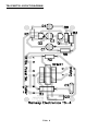
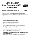
TS4 PARTS LAYOUT DIAGRAM
TS4 • 6
KIT PARTS LIST
Sort and “check off” the components in the boxes provided. We do our best to
pack all our kits correctly, but it is possible that a mistake has occurred and we
missed a part. Please note that physical descriptions of parts are for those
currently being shipped. Sometimes the parts in your kit may have a different
appearance but still have the same values.
1
2
2
1
2
1
2
1
1
1
1
6
.001 uF disc capacitor [marked .001, 102, or 1 nF] [C2]
100 ohm resistors [R1, R2]
33 uF electrolytic capacitors [C1, C3]
1K ohm 1/2 watt resistor [brown-black-red] [R4]
47K ohm resistors [yellow-purple-orange] [R5,R6]
33K ohm resistor [orange-orange-orange] [R3]
Small NPN transistors, [type 2N3904 or equivalent] [Q1, Q2]
Large NPN power transistor [marked JE200] [Q3]
Jumbo green LED (Light Emitting Diode) (D1)
PC-mount transformer (XFMR1)
TS4 printed circuit board
lengths of wire
TS4 • 7
TS4 PC BOARD ASSEMBLY STEPS
1. Identify and install the NPN 2N3904 transistors Q1 and Q2. Make sure
the flat sides face R1 as shown on the circuit board.
2. Install R1,100 ohm resistor (brown-black-brown). Save one of the
snipped off leads to use as a jumper for the points labeled E and F.
3. Install R6, 47K resistor (yellow-violet-orange), next to Q1.
4. Install D1, jumbo green LED. You’ll notice that the silkscreen for the part
shows a flat side. Orient the flat side on the diode with the flat side on the
silkscreen. Leave the leads as long as you wish depending on how you
want to mount your TS4 kit and if you’re not sure, leave them long; you can
always cut them down later but it’s not easy to make the leads longer
again!
5. Install R2, 100 ohm resistor (brown-black-brown), next to R6.
6. Install XFMR1. The transformer only goes in one way but the leads on
this part are extremely fragile and you cannot bend them as you normally
would to hold the part in place. Once the transformer is placed in the PC
board flip the board over so that it rests flat on the transformer; then the
part will be flat to the PC board and you can solder the leads into place.
This part, along with Q3, R4, and C2 form the high voltage oscillator that
generates the zap.
7. Install C3, 33uF electrolytic capacitor between Q1 and Q2. Be sure the
polarity is correct. The “+” on the circuit board needs to go with the positive
side of the cap and this lead is usually longer. The cap has a “-” stripe on it.
The other lead is “+”. If you are a regular Ramsey kit builder, this section of
circuitry may be starting to look familiar. It’s the Blinky Kit!!! It sits happily
next to the high voltage part of the circuit blinking away to lure in victims.
8. Install C1, 33uF electrolytic capacitor. Observe polarity again.
9. Install R5, 47K resistor (yellow-violet-orange), next to C1.
10. Install R3, 33K resistor (orange-orange-orange).
11. Install R4, 1K 1/2 Watt resistor (brown-black-red), under XFMR1. Be
careful when your kit is running; this resistor gets a bit toasty.
12. Install Q3, the big NPN transistor, under R4. This transistor may have
pre-bent leads that don’t line up the way they are supposed to be on the
board. Be sure the metal back faces the transformer, even if you have to
rebend the leads.
13. Install C2, .001uF capacitor (marked 102), across from Q3.
14. Solder a piece of cutoff component lead into the holes marked “Tilt Sw.”
TS4 • 8
You can form the lead into the shape of a very small staple, place it
through the PC board across those two holes and solder it into place. If
you decide to use a tilt switch in the future you would mount it across
these two points.
15. Solder two wires into the holes marked “Power Sw.” for the switch that
you get to provide.
16. Solder two pieces of wire into the holes marked “Power”. If you find it
confusing to use the same color wire for both the positive and the negative
inputs you can use your own red or other alternate color wire in the hole
marked “+”.
17. Lastly, solder two wires into the holes marked “Output” (one is marked
with a “+” sign and one with a “-” sign). These are the high voltage output
wires where you’ll connect your touch pads.
You’re all done!
SETUP AND TESTING
Now it’s time to power up. Your output wires need to be touching a metal
object to give you a good zap. You could attach them to little pieces of tin foil,
about a square inch or so. You could also solder them to little pieces of
copper-clad circuit board. Metal washers will work as well. When you have
something attached to them, twist together the two wires attached to the holes
marked “Power Sw.”; this is like turning the switch to the “on” position. Then
apply 3V-6V DC to the input wires from your battery, battery pack, or other DC
power source. Observe polarity! The DC positive is connected to the wire in
the hole marked “+” and the negative is connected to the wire in the hole
marked “-”. Warning, 6V will zap you pretty good! You might try 3V first. Go
ahead and touch the output pads you made and enjoy the shock.
Another warning: If you have a scope probe connected to the output leads to
see the voltage waveform you will get a surprise when you touch the output
pads! The shock will be much greater. This phenomenon is a hint at a way of
possibly juicing up your tickle stick without drawing any more power.
Once you know that the unit is operating correctly you can add a power switch
if you wish. It is recommended that you test the unit by twisting the wires
together first so that you know the kit works properly before adding another
element such as a power or tilt switch. If you went ahead and installed a
power switch before you read this and your Tickle Stick doesn’t seem to be
operating properly, check the troubleshooting section first, then remove your
power switch as a possible source of the problem and try it again.
TS4 • 9
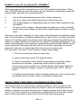
HAVING FUN WITH THE TICKLE STICK
The success of the TS4 as a novelty depends on your ingenuity in concealing
its real purpose while building it into some object that people are likely to
handle or fondle. Also, you need a clever way of turning it on and off easilywithout getting shocked yourself! A good way to approach your own design is
to think about how we designed our own prototype:
1). We used a plastic or cardboard food container, about the size of a food
can, for which there is a well-fitting press-on lid. Or, use one of those
promotional beverage cups that comes with its own lid.
2). Around the outside of the container, wrap TWO separate metal bands in
whatever way that a person is most likely to touch BOTH of them when
picking up the object. You can use aluminum foil, and a very neat installation
might be made with strips of self-adhesive window foil as used in security
systems.
3). The two metallic bands are the contact points for the two high-voltage
output wires from the TS4. So it should be obvious that the wires from the
points marked “Output +” and “Output -” are connected to the bands through
small holes in the container.
4). The switch may be concealed inside the container or in very plain view to
attract curiosity. It can be a manual slide or toggle switch, or a mercury switch,
depending on how you expect your "object" to be handled. Whether the
flashing LED is visible is up to you.
5). You may also choose to leave the LED flashing and switch only the highvoltage on and off (to conserve battery life). You may do this by removing the
jumper soldered in to the holes marked “Tilt Sw.”. Solder in a Mercury or Tilt
switch in its place. Now, the high voltage will be active only when the tilt switch
is closed. The flashing LED remains on attracting your next victim!
Now that you have a mental picture of our prototype, put your own
imagination to work. What about two tuna cans at each end of a short plastic
or cardboard tube? What about a "book" with fancy metallic covers? A small,
inexpensive telescope or kaleidoscope? A microphone, hollowed-out tennis
racquet or baseball bat? Some sort of regional souvenir or curio? A very
ordinary-looking flashlight just waiting for somebody to pick it up and fiddle
with it? And, don't forget a nice big ribbon bow on an inviting looking box!
TS4 • 10
For visitors to your shop, what about something very ordinary like some 2" to
3" PVC with a couple of innocent-looking hose clamps mounted in the "right"
places? What about a videogame joystick, peppermill, or something that looks
like a VCR remote control box? For your electronics-minded "what new
gadget did you build now?" friends, see if you can successfully insulate the
two halves of a plain aluminum "mini box" from each other!
When you get the nerve to grasp your Tickle Stick firmly yourself - and hold
on! - you'll notice the LED flashing more brightly and you will actually feel a
series of voltage pulses.
OTHER APPLICATIONS
A recent hamfest customer felt that the TS4 could be wired up to discourage a
neighborhood cat from using a spot in his garage as a litter box. We're not
sure how he was going to do this, but he sure seemed determined. To be
honest, we're just not sure what else you'd do with the Tickle Stick. That's your
department! Also, we are asked whether the TS4 is like a "stun gun". The
answer is that the principles are similar but that stun guns deliver 60 to 120
kilovolts! For classroom discussions, the TS4 output can be connected to an
AC voltmeter. Its output can light a standard NE-2 neon lamp.
The circuit will NOT deliver a higher voltage output in direct proportion to the
DC input. The unit works well at the recommended 3 to 6 volts input,
producing about 80 volts output. Attempts to increase the input voltage will
cause the transistor circuitry to draw considerably more current, which may
cause heat damage to R4 with no significant output voltage increase.
TS4 • 11
TROUBLESHOOTING GUIDE
If your kit doesn’t work it’s most likely a transistor installed incorrectly or a polarized component in backwards. Just make sure the transistors are lined up correctly and the electrolytic caps are in the right way. Also be sure you twisted the
ends of the wires in the holes marked “Power Sw.” together, otherwise your kit
is never turned on and cannot work! If the LED doesn’t light it is probably in
backwards. If all this checks out, make sure the right resistors are in the right
places. Also, while it is usually possible to feel a slight “jolt” from the bare wires
attached to the high voltage output, you must have a larger touch surface to get
the full effect of the shock. Your kit may be working but you won’t feel much until you attach your metal touch plates so try that first.
A FINAL WORD ABOUT THE APPROPRIATE USE OF HIGH VOLTAGE
As we emphasized in the beginning, it really is up to YOU to use the good judgment necessary to know who will enjoy the TS4 for the fun it is intended to be,
and who may become very angry about it. People DO have the basic right not
to experience an electrical shock of any kind. This feeling can be based on simple unfamiliarity with electricity, fear (a very real phobia), or a serious and
knowledgeable respect for electricity.
While writing this manual I had a chance to watch people’s reactions to the
Tickle Stick at a Hamfest. I told them EXACTLY what it was and what to expect.
A number of kids and other folks cheerfully accepted the Tickle Stick challenge
and said it was fun. Two different radio Hams said there was no way they would
pick it up, saying that it’s crazy to want to be shocked intentionally, especially
with 80 volts.
If someone were to become upset with you after encountering your Tickle Stick
you would be at their mercy if they decided to really complain about it. The burden of proving that you did not intend any harm and that your Tickle Stick is not
dangerous would rest squarely on you. People have a right not to want to have
anything to do with your Tickle Stick. Enough said? Ramsey Electronics, Inc.
shall not be liable for any consequences of any kind arising from any person’s
use of these kit components in any manner whatsoever.
We sell this kit with the belief that you know something about electricity and
safety. This kit, as properly assembled, is not dangerous, and probably could
not be made to be dangerous; BUT, given the fact that some people have
health problems and may be more susceptible to electric currents running
through their body than others, you should not indiscriminately shock people.
Use good judgment.
TS4 • 12
Anyway . . . have some fun with your Tickle Stick!
TS4 • 13
TS4 • 14
The Ramsey Kit Warranty
Please read carefully BEFORE calling or writing in about your kit. Most
problems can be solved without contacting the factory.
Notice that this is not a "fine print" warranty. We want you to understand your rights and ours too! All
Ramsey kits will work if assembled properly. The very fact that your kit includes this new manual is
your assurance that a team of knowledgeable people have field-tested several "copies" of this kit
straight from the Ramsey Inventory. If you need help, please read through your manual carefully, all
information required to properly build and test your kit is contained within the pages! However,
customer satisfaction is our goal, so in the event that you do have a problem, take note of the
following.
1. DEFECTIVE PARTS: It's always easy to blame a part for a problem in your kit, Before you conclude
that a part may be bad, thoroughly check your work. Today's semiconductors and passive components
have reached incredibly high reliability levels, and its sad to say that our human construction skills
have not! But on rare occasions a sour component can slip through. All our kit parts carry the Ramsey
Electronics Warranty that they are free from defects for a full ninety (90) days from the date of
purchase. Defective parts will be replaced promptly at our expense. If you suspect any part to be
defective, please mail it to our factory for testing and replacement. Please send only the defective part
(s), not the entire kit. The part(s) MUST be returned to us in suitable condition for testing. Please be
aware that testing can usually determine if the part was truly defective or damaged by assembly or
usage. Don't be afraid of telling us that you 'blew-it', we're all human and in most cases, replacement
parts are very reasonably priced.
2. MISSING PARTS: Before assuming a part value is incorrect, check the parts listing carefully to see
if it is a critical value such as a specific coil or IC, or whether a RANGE of values is suitable (such as
"100 to 500 uF"). Often times, common sense will solve a mysterious missing part problem. If you're
missing five 10K ohm resistors and received five extra 1K resistors, you can pretty much be assured
that the '1K ohm' resistors are actually the 'missing' 10 K parts ("Hum-m-m, I guess the 'red' band
really does look orange!") Ramsey Electronics project kits are packed with pride in the USA. If you
believe we packed an incorrect part or omitted a part clearly indicated in your assembly manual
supplied with the basic kit by Ramsey, please write or call us with information on the part you need
and proof of kit purchase.
3. FACTORY REPAIR OF ASSEMBLED KITS:
To qualify for Ramsey Electronics factory repair, kits MUST:
1. NOT be assembled with acid core solder or flux.
2. NOT be modified in any manner.
3. BE returned in fully-assembled form, not partially assembled.
4. BE accompanied by the proper repair fee. No repair will be undertaken until we have received the
MINIMUM repair fee (1/2 hour labor) of $18.00, or authorization to charge it to your credit card
account.
5. INCLUDE a description of the problem and legible return address. DO NOT send a separate letter;
include all correspondence with the unit. Please do not include your own hardware such as
nonRamsey cabinets, knobs, cables, external battery packs and the like. Ramsey Electronics, Inc.,
reserves the right to refuse repair on ANY item in which we find excessive problems or damage due
to construction methods. To assist customers in such situations, Ramsey Electronics, Inc., reserves
the right to solve their needs on a case-by-case basis.
The repair is $36.00 per hour, regardless of the cost of the kit. Please understand that our technicians
are not volunteers and that set-up, testing, diagnosis, repair and repacking and paperwork can take
nearly an hour of paid employee time on even a simple kit. Of course, if we find that a part was
defective in manufacture, there will be no charge to repair your kit (But please realize that our
technicians know the difference between a defective part and parts burned out or damaged through
improper use or assembly).
4. REFUNDS: You are given ten (10) days to examine our products. If you are not satisfied, you may
return your unassembled kit with all the parts and instructions and proof of purchase to the factory for
a full refund. The return package should be packed securely. Insurance is recommended. Please do
not cause needless delays, read all information carefully.
TS4 • 15
TS4 Tickle Stick
Quick Reference Page Guide
Introduction to the TS4 ...................................... 4
TS4 Circuit Description ..................................... 4
Parts Layout Diagram ....................................... 6
Parts List ........................................................... 7
Schematic Diagram ......................................... 14
Ramsey Kit Warranty ....................................... 15
REQUIRED TOOLS
• Soldering Iron Ramsey WLC100
• Thin Rosin Core Solder Ramsey RTS12
• Needle Nose Pliers Ramsey MPP4 or
RTS05
• Small Diagonal Cutters Ramsey RTS04
<OR> Technician’s Tool Kit TK405
ADDITIONAL SUGGESTED ITEMS
• Holder for PC Board/Parts Ramsey HH3
• Desoldering Braid Ramsey RTS08
• Digital Multimeter Ramsey M133
RAMSEY ELECTRONICS, INC.
590 Fishers Station Drive
Victor, New York 14564
Phone
(585) 924-4560
Fax
(585) 924-4555
www.ramseykits.com
TS4 • 16
TOTAL SOLDER POINTS
44
ESTIMATED ASSEMBLY
TIME
Beginner .............. 1.5hrs
Intermediate ........ 1 hrs
Advanced ............ 0.5 hrs