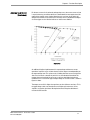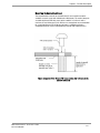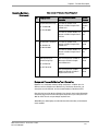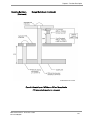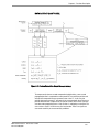
1
Chapter 3 – Receiver Description
3.0 RECEIVER DESCRIPTION
CHAPTER SUMMARY
Refer to this chapter for the following:
•
A simplified functional description of the operation of the Oncore receiver
•
Antenna power and gain requirements
•
Physical size and electrical connections of the Oncore receiver
•
Oncore receiver technical characteristics and operating features
•
Installation precautions and considerations
•
Oncore receiver mounting guidelines
•
Interface protocol description
•
Operational modes of the Oncore receiver
•
Additional customizing capabilities and operation
Motorola GPS Products - Oncore User’s Guide
Revision 5.0 08/30/02
3.1
Chapter 3 – Receiver Description
DETAILED TABLE OF CONTENTS
Overview ...................................................................................................................................3.4
Antenna Sense Circuit............................................................................................................3.6
Antenna Feed Current............................................................................................................3.6
Active Antenna Configuration ...............................................................................................3.8
M12+ and M12+ Timer Oncore Receiver Electrical Connections ...................................3.9
Oncore Operation Voltage And Current Ranges................................................3.9
M12+ Oncore Receiver Printed Circuit Board ..................................................................3.10
M12+ Oncore Receiver Technical Characteristics..........................................................3.11
M12+ Timer Oncore Receiver Technical Characteristics ..............................................3.12
GT+, UT+, SL Oncore Receiver Electrical Connections ..................................................3.13
Oncore Operation Voltage And Current Ranges..............................................3.13
GT+, UT+, SL Oncore Receiver Printed Circuit Board .....................................................3.14
GT+ Oncore Receiver Technical Characteristics ............................................................3.15
UT+ Oncore Receiver Technical Characteristics ............................................................3.16
SL Oncore Receiver Technical Characteristics ...............................................................3.17
1PPS Signal Definition ..........................................................................................................3.18
RF Jamming Immunity (UT Model Only).............................................................................3.18
Adaptive Tracking Loops .....................................................................................3.19
Automatic Site Survey (UT Model Only) ............................................................................3.20
100PPS Output (UT Model Only)..........................................................................................3.21
Time Raim Algorithm Description (M12 Timing and UT Models Only)..........................3.22
Receiver Module Installation ..............................................................................................3.24
Installation Precautions And Considerations ...................................................................3.24
Electrostatic Precautions ....................................................................................3.24
Electromagnetic Considerations ........................................................................3.24
RF Shielding............................................................................................................3.25
Real-Time Clock (RTC)..........................................................................................3.25
Thermal Considerations .......................................................................................3.25
Grounding Considerations ...................................................................................3.25
Oncore Receiver Mounting Instructions (GT+/UT+ Only)...............................................3.26
Mounting Hardware Design Guidelines ............................................................3.26
Design and Process Validation Test Information ............................................3.28
Sturdiness and Reliability of Metal Standoffs ..................................................3.29
Design Worksheets...............................................................................................3.29
Mean Time Between Failure (MTBF) .................................................................................3.31
Motorola GPS Products - Oncore User’s Guide
Revision 5.0 08/30/02
3.2
Chapter 3 – Receiver Description
System Integration ................................................................................................................3.32
Interface Protocol .................................................................................................................3.32
TTL Output...............................................................................................................................3.33
Motorola Binary Format .......................................................................................3.34
NMEA Support.......................................................................................................3.37
RTCM Differential GPS Support..........................................................................3.38
EXCLUSIVE-OR Checksum Creation...................................................................................3.39
Millisecond To Degree Conversion ....................................................................................3.40
Input/Output Processing Time.............................................................................................3.41
DATA Latency ........................................................................................................................3.42
Position DATA Latency.........................................................................................3.44
Velocity DATA Latency.........................................................................................3.44
Time DATA Latency ..............................................................................................3.44
One Pulse Per Second (1PPS) Timing................................................................................3.44
Measurement Epoch Timing ...............................................................................3.44
Output Data Timing Relative To Measurement Epoch....................................3.45
1PPS Cable Delay and 1PPS OfFset (M12 Timing and UT Model Only)........3.46
Operational Considerations .................................................................................................3.47
First Time On ..........................................................................................................3.47
Initialization ............................................................................................................3.48
Shut Down ..............................................................................................................3.48
Keep Alive Power..................................................................................................3.48
Rollovers In Time ...................................................................................................................3.49
Received Carrier To Noise Density Ratio (C/NO) .............................................................3.50
Motorola GPS Products - Oncore User’s Guide
Revision 5.0 08/30/02
3.3
Chapter 3 – Receiver Description
About the
Oncore
OVERVIEW
The Oncore receiver provides position, velocity, time, and satellite tracking status
information via a serial port.
A simplified functional block diagram of the Oncore receiver is shown in the following
illustration.
Figure 3.1: Oncore Receiver Functional Block Diagram
Motorola GPS Products - Oncore User’s Guide
Revision 5.0 08/30/02
3.4
Chapter 3 – Receiver Description
Simplified Block
Diagram Description
OVERVIEW (CONTINUED)
The Oncore Receiver has an eight channel design (12-channel design for the
M12+) capable of tracking eight (twelve for M12+) satellites simultaneously. The
module receives the Ll GPS signal (1575.42 MHz) from the antenna and operates off
the coarse/acquisition (C/A) code tracking. The code tracking is carrier aided. The
Oncore receiver must be powered with regulated +5 V (Nominal 3V for M12+) power.
Time recovery capability is inherent in the architecture. The UT Oncore is designed
specifically for precise timing applications.
The Ll band signals transmitted from GPS satellites are collected by a low-profile,
microstrip patch antenna, passed through a narrow-band bandpass filter, and then
amplified by a signal preamplifier contained within the antenna module. Filtered and
amplified Ll band signals from the antenna module are then routed to the RF signal
processing section of the receiver module via a single coaxial interconnecting cable.
This interconnecting cable also provides the +5 V (Nominal 3V for M12+) power
required for signal pre-amplification in the antenna module.
The RF signal processing section of the Oncore receiver printed circuit board (PCB)
contains the required circuitry for down-converting the GPS signals received from
the antenna module. The resulting intermediate frequency (IF) signal is then passed
to the eight channel code and carrier correlator section of the Oncore receiver PCB
where a single, high speed analog-to-digital (AD) converter converts the IF signal to a
digital sequence prior to channel separation. This digitized IF signal is then routed to
the digital signal processor (also contained within the eight channel code and carrier
correlator section) where the signal is split into eight parallel channels for signal
detection, code correlation, carrier tracking, and filtering.
The processed signals are synchronously routed to the position microprocessor
(MPU) section. This section controls the GPS receiver operating modes and decodes
and processes satellite data and the pseudorange and delta range measurements
used to compute position, velocity, and time. In addition, the position processor
section contains the inverted TTL serial interface.
Warning
Keep-alive random access memory (RAM) is provided for the retention of satellite
ephemeris data, custom operating parameters, almanac information, and other
information, as specified in Chapter 5. To prevent loss of this information when the
Oncore receiver is powered off, an external +5 V (Nominal 3V for M12+) BATT
voltage is required. Retention of the real-time-clock (RTC) value also requires the
external +5 V (Nominal 3V for M12+) BATT signal when the Oncore receiver is
powered off.
Motorola GPS Products - Oncore User’s Guide
Revision 5.0 08/30/02
3.5
Chapter 3 – Receiver Description
ANTENNA SENSE CIRCUIT
The Oncore receiver is capable of detecting the presence of an antenna. The
receiver utilizes an antenna sense circuit that can detect under current (open
condition), over current (shorted or exceeding maximum receiver limits), or a valid
antenna connection. The antenna sense circuit was designed around the Motorola
GPS antenna; therefore non Motorola antennas may exceed the threshold limits as
listed below
Under current circuit @ 25 degC:
Good indication:
greater than 5 mA
Bad indication:
less than 5 mA
Over current circuit @ 25 degC:
80 mA maximum for normal operation
45 mA maximum for short circuit
The above information is output in the following I/O messages, @@Ea (8-Channel
Position/Status/Data Output), @@Fa (8-Channel SelfTest), @@Ha
(Position/Status/Data 12-Channel), @@Ia (Self-Test Message 12-Channel). Upon
detecting an over current situation, the receiver will automatically shut down the antenna
feed section until the fault is cleared. Upon detecting an under current situation, the
receiver will continue to operate as normal, but will flag the fault mode in the two 1/O
messages. An external power source must be used if the antenna circuit power
requirements exceed the limits.
ANTENNA FEED CURRENT
The Oncore receiver now provide up to 80 mA of current via the antenna power
supply circuit. The circuit still has a short protection and a means for detecting over
current and open circuit conditions of the connection between it and the antenna.
This allows the user a degree of confidence that the antenna is connected and
drawing current. This feature can eliminate hours of troubleshooting, especially in a
new installation.
The antenna power supply circuit consists of a current sense resistor, two rail to rail
operational amplifiers, a pass transistor and a voltage divider to set the upper and
lower limits of the under current and over current thresholds. The operational
amplifiers compare the voltage developed across the current sense resistor with
these thresholds. if the antenna is drawing 5 mA or more, the first operational
amplifier will produce a logic level to the digital circuits where it is monitored by the
firmware. if the signal is absent, indicating an under current condition, an alarm bit is
set to alert the user.
Motorola GPS Products - Oncore User’s Guide
Revision 5.0 08/30/02
3.6
Chapter 3 – Receiver Description
Antenna Feed Circuit
(Continued)
For the over current circuit, when the voltage drop across the current sense resistor
is equal to the over current threshold (set at about 90 mA for room temperature) the
output of the amplifier starts shutting down the pass transistor. At this point, the
voltage to the antenna starts to decrease and a logic level is provided for the digital
circuit to trigger an alarm bit that indicates an overcurrent condition.
Figure: 3.2
An additional feed back path between this output voltage and the over current
operational amplifier causes a further decrease in the output current depending on
the output voltage level. This action results in folding back the current such that the
short circuit amount is about 45 mA, which is less than the 90 mA threshold. This
prevents the over heating of the series pass transistor should the shorted coax
condition occur. A chart of the typical output voltage vs. the load current is shown in
figure 3.2 above.
The output current limit is higher than previous versions of Oncore receivers. This is
to support longer cable runs through the use of higher gain antennas or in-line
amplifiers so that the signal does not drop below the tracking threshold when it
reaches the GPS receiver.
Motorola GPS Products - Oncore User’s Guide
Revision 5.0 08/30/02
3.7
Chapter 3 – Receiver Description
External Gain Range
ACTIVE ANTENNA CONFIGURATION
The recommended external gain (antenna gain minus cable and connector losses) for
the GT Oncore R3 model is 10 to 26 dB. The recommended external gain for the UT
Oncore R5 model is 10 to 33 dB. A typical antenna system might have an active
antenna with 24 dB of gain and six meters of cable with 6 dB of loss. The external
gain would then be 18 dB, which is within the acceptable range. For more
information, refer to the Active Antenna Applications Note.
Figure 3.3: Oncore Receiver
Motorola GPS Products - Oncore User’s Guide
Revision 5.0 08/30/02
3.8
Chapter 3 – Receiver Description
M12+ AND M12+ TIMER ONCORE RECEIVER ELECTRICAL
CONNECTIONS
The M12+ and M12+ Timer receives electrical power and receives/transmits I/O
signals through a 10pin power/data connector mounted on the Oncore. Refer to
Figure 3.3 for pin numbering.
The following table lists the assigned signal connections of the Oncore receiver's
power/data connector. For more information, refer to the Active Antenna
Applications Note.
Table 3.1: Oncore Power/Data Connector Pin Assignments
Pin #
Signal Name
Description
1
TTL TXD1
Transmit 3V logic
2
TTL RXD1
Receive 3V logic
3
+3V PWR
Regulated main power
4
1PPS
One per pulse per second signal
5
GROUND
Ground (receiver)
6
BATTERY
Externally applied backup power
7
Reserved
Not currently used
8
RTCM IN
RTCM input only
9
Antenna Voltage
3 V to 5 V antenna input voltage
10
Reserved
Not currently used
Oncore Operation Voltage And Current Ranges
3V PWR (Main power)
Voltage:
2.85V to 3.15V regulated
50 mV peak-to-peak ripple
Current:
0.225 W maximum (without antenna)
BATTERY (Externally applied backup power)
Voltage:
2.2V to 3.2V
Current:
5 uA typical @ 2.7V @25 degC
Retention
Backup power retains date, time, position, satellite data,
oscillator learning table and operating mode.
Motorola GPS Products - Oncore User’s Guide
Revision 5.0 08/30/02
3.9
Chapter 3 – Receiver Description
M12+ ONCORE RECEIVER PRINTED CIRCUIT BOARD
Figure 3.4: M12+ and M12+ Timer Oncore Printed Circuit Board Layout
Motorola GPS Products - Oncore User’s Guide
Revision 5.0 08/30/02
3.10
Chapter 3 – Receiver Description
M12+ ONCORE RECEIVER TECHNICAL CHARACTERISTICS
Table 3.2: Oncore Technical Characteristics – M12+ Model
GENERAL
CHARACTERISTICS
PERFORMANCE
CHARACTERISTICS
Receiver Architecture
Tracking Capability
Dynamics
Acquisition Time
(Time To First Fix, TTFF)
(Tested at –30 to +85ºC)
Positioning Accuracy
Timing Accuracy
(1 Pulse per second, 1 PPS)
Antenna Requirements
SERIAL
COMMUNICATION
ELECTRICAL
CHARACTERISTICS
PHYSICAL
CHARACTERISTICS
ENVIRONMENTAL
CHARACTERISTICS
MISCELLANEOUS
NOTES
Motorola GPS Products - Oncore User’s Guide
Revision 5.0 08/30/02
12 channel
L1 1575.42 MHz
C/A code (1.023 MHz chip rate)
Code plus carrier tracking (carrier aided tracking)
12 simultaneous satellite vehicles
Velocity: 1000 knots (515 m/s) > 1000 knots (515 m/s); at
altitudes < 60,000 ft. (18,000m)
Acceleration: 4g
Jerk: 5 m/s3
Vibration: 7.7G per Military Standard 810E
15s typical TTFF-hot (with current almanac,position,time and ephemeris)
40s typical TTFF-warm (with current almanac, position, and time)
60s typical TTFF-cold (no stored information)
< 1.0s internal reacquisition (typical)
100 meters 2dRMS with SA as per DoD specification
Less than 25 m SEP without SA
< 500nS with SA on
Active antenna module powered by receiver module
18dB to 36dB external antenna gain measured at input to receiver
3 V or 5 V Antenna power provided via header connector
Datum
WGS-84 Default
One user definable datum
Output Messages
Latitude, longitude, height, velocity, heading, time
Motorola binary protocol at 9600 baud
NMEA 0183 at 4800 baud (GGA,GLL, GSV, RMC, VTG, ZDA)
Software selectable output rate (continuous or poll)
TTL interface (0 to 3 V)
Second COM port for RTCM input
Power Requirements
2.85 to 3.15 Vdc; 50 mVp-p ripple (max)
“Keep-Alive” BATT Power
External 2.2 Vdc to 3.2 Vdc, 5 uA typical @ 2.7 Vdc @ 25ºC
Power Consumption
< 185mW @ 3 V without antenna
Dimensions
40.0 x 60.0 x 10.0 mm (1.57 x 2.36 x 0.39 in.)
Weight
Receiver 25 g (0.9 oz.)
Active Antenna Module < 40 g
Connectors
Data/power: 10 pin (2 x 5) unshrouded header on 0.050 in.
centers (available in right angle or straight configuration)
RF: right angle MMCX (subminiature snap-on)
Antenna to Receiver
Single coaxial cable
Interconnection
Antenna sense circuit
Operating Temperature
-40ºC to +85ºC
Storage Temperature
-40ºC to +105ºC
Humidity
95% over dry bulb range of +38ºC to +85ºC
Altitude
18,000 m (60,000 ft.) maximum
> 18,000 m (60,000 ft.) for velocities
< 515 m/s (1000 knots)
Standard Features
Motorola DGPS corrections at 9600 baud on COM port one
RTCM SC-104 input Type 1 and Type 9 messages for DGPS
at 2400, 4800 or 9600 baud on COM port two
NMEA 0138 output
Inverse DGPS support
Optional Features
Lithium battery backup
All specifications typical and quoted at 25°C unless otherwise specified
3.11
Chapter 3 – Receiver Description
M12+ TIMER ONCORE RECEIVER TECHNICAL CHARACTERISTICS
Table 3.2: Oncore Technical Characteristics – M12+ Timer Model
GENERAL
CHARACTERISTICS
PERFORMANCE
CHARACTERISTICS
SERIAL
COMMUNICATION
ELECTRICAL
CHARACTERISTICS
PHYSICAL
CHARACTERISTICS
ENVIRONMENTAL
CHARACTERISTICS
MISCELLANEOUS
NOTE
Motorola GPS Products - Oncore User’s Guide
Revision 5.0 08/30/02
Receiver Architecture
12 channel
L1 1575.42 MHz
C/A code (1.023 MHz chip rate)
Code plus carrier tracking (carrier aided tracking)
Tracking Capability
12 simultaneous satellite vehicles
Dynamics
Velocity: 1000 knots (515 m/s) > 1000 knots (515 m/s); at
altitudes < 60,000 ft.(18,000m)
Acceleration: 4g
Jerk: 5 m/s3
Vibration: 7.7G per Military Standard 810E
Acquisition Time
200s TTFF-hot (with current almanac,position,time and ephemeris)
(Time To First Fix, TTFF)
50s TTFF-warm (with current almanac, position, and time)
25s TTFF-cold (No stored information)
(Tested at –30 to +85ºC)
< 1.0s internal reacquisition (typical)
Positioning Accuracy
100 meters 2dRMS with SA as per DoD specification
Less than 25 m SEP without SA
Timing Accuracy
Performance using clock granularity message*
(1 Pulse per second
< 2nS 1 Sigma average
or, 100 PPS)
< 6nS 6 Sigma average
Position hold mode active
Performance not using clock granularity message*
< 10nS 1 Sigma average
< 20nS 6 Sigma average
Antenna Requirements
Active antenna module powered by receiver module
18dB to 36dB external antenna gain measured at input to receiver
3 V or 5 V Antenna power provided via header connector
Datum
WGS-84 Default
One user definable datum
Output Messages
Latitude, longitude, height, velocity, heading, time
Motorola binary protocol at 9600 baud
Software selectable output rate (continuous or poll)
TTL interface (0 to 3 V)
Power Requirements
2.85 to 3.15 Vdc; 50 mVp-p ripple (max)
“Keep-Alive” BATT Power
External 2.2 Vdc to 3.2 Vdc, 5 uA typical @ 2.7 Vdc @ 25ºC
Power Consumption
<185mW @ 3 V without antenna
Dimensions
40.0 x 60.0 x 10.0 mm (1.57 x 2.36 x 0.39 in.)
Weight
Receiver 25 g (0.9 oz.)
Active Antenna Module < 40 g
Connectors
Data/power: 10 pin (2 x 5) unshrouded header on 0.050 in.
centers (available in right angle or straight configuration)
RF: right angle MMCX (subminiature snap-on)
Antenna to Receiver
Single coaxial cable
Interconnection
Antenna sense circuit
Operating Temperature
-40ºC to +85ºC
Storage Temperature
-40ºC to +105ºC
Humidity
95% over dry bulb range of +38ºC to +85ºC
Altitude
18,000 m (60,000 ft.) maximum
> 18,000 m (60,000 ft.) for velocities
< 515 m/s (1000 knots)
Standard Features
Motorola Binary Protocol
Position hold with automatic site survey
Clock Granularity Error Message
T-RAIM (Timing Receiver Autonomous
Integrity Monitoring)
Optional Features
Lithium battery backup
All specifications typical and quoted at 25°C unless otherwise specified
3.12
Chapter 3 – Receiver Description
GT+, UT+, SL ONCORE RECEIVER ELECTRICAL CONNECTIONS
The Oncore receives electrical power and receives/transmits I/O signals through a
10pin power/data connector mounted on the Oncore Refer to Figure 3.3 for pin
numbering.
The following table lists the assigned signal connections of the Oncore receiver's
power/data connector. For more information, refer to the Active Antenna
Applications Note.
Table 3.3: Oncore Power/Data Connector Pin Assignments
Pin #
Signal Name
Description
1
BATTERY
Externally applied backup power (< + 5V)
2
+5V PWR
+5V regulated main power
3
GROUND
Ground (receiver)
4
VPP
Flash memory programming voltage
5
RTCM IN
RTCM input
6
1PPS
One per pulse per second signal
7
1PPS RTN
One per pulse per second return
8
TTL TXD
Transmit 5V logic
9
TTL RXD
Receive 5V logic
10
TTL RTN
Transmit/receive return
Oncore Operation Voltage And Current Ranges
5V PWR (Main power)
Voltage:
4.75 V to 5.25 V
50 mV peak-to-peak ripple
Current:
< 0.9 W at 5 V at 25øC with active antenna drawing 20 mA
BATTERY (Externally applied backup power)
Voltage:
2.5 V to 5.25 V
Current:
5 uA typical @ 2.5 V
100 uA typical @ 5.0 V
Motorola GPS Products - Oncore User’s Guide
Revision 5.0 08/30/02
3.13
Chapter 3 – Receiver Description
GT+, UT+, SL ONCORE RECEIVER PRINTED CIRCUIT BOARD
Figure 3.5: Oncore Printed Circuit Board Layout UT, GT and SL
Motorola GPS Products - Oncore User’s Guide
Revision 5.0 08/30/02
3.14
Chapter 3 – Receiver Description
GT+ ONCORE RECEIVER TECHNICAL CHARACTERISTICS
Table 3.4: Oncore Technical Characteristics – GT Plus Model
General
Characteristics
Performance
Characteristics
Receiver Architecture
Tracking Capability
Dynamics
Acquisition Time
(Time To First Fix, TTFF)
(Tested at –30 to +85ºC)
Positioning Accuracy
Timing Accuracy
(1 Pulse Per Second, 1 PPS)
Antenna
Datum
Serial
Communication
I/O Messages
Electrical
Characteristics
Power Requirements
“Keep-Alive” BATT Power
Power Consumption
Dimensions
Weight
Connectors
Physical
Characteristics
Environmental
Characteristics
Miscellaneous
Antenna to Receiver
Interconnection
Operating Temperature
Humidity
Altitude
Standard Features
Optional Features
Motorola GPS Products - Oncore User’s Guide
Revision 5.0 08/30/02
8 parallel channel
L1 1575.42 MHz
C/A code (1.023 MHz chip rate)
Code plus carrier tracking (carrier aided tracking)
8 simultaneous satellite vehicles
Velocity: 1000 knots (515 m/s); > 1000 knots at altitudes < 60,000 ft.
Acceleration: 4g
3
Jerk: 5 m/s
Vibration: 7.7G per Military Standard 810E
< 15 s typical TTFF-hot (with current almanac, position, time and
ephemeris)
< 45 s typical TTFF-warm (with current almanac, position, and time)
< 90 s typical TTFF-cold
< 1.0 s internal reacquisition (typical)
100 m 2dRMS with SA as per DoD specification
Less than 25 m SEP without SA
1-5 m typical in differential mode
< 500 ns (1 sigma) with SA on
Active micro strip patch antenna module
Powered by receiver module (5-80 mA @ 5 V)
WGS-84
One user definable datum
Latitude, longitude, height, velocity, heading, time
Motorola binary protocol at 9600 baud
NMEA at 4800 baud: GGA, GLL., GSA, GSV, RMC, VTG,ZDA
Software selectable output rate (continuous or poll)
TTL interface (0 to 5 V)
Second COM port for RTCM input
5 ± 0.25 V; 50 mVp-p ripple (max)
External 2.5 V to 5.25 V; 5 uA typical @ 2.5 V
<0.9 W @ 5 V with active antenna drawing 20 mA
2.00 x 3.25 x 0.64 in. (50.8 x 82.6 x 16.3 mm)
1.8 oz (51g)
Data/power: 10 pin (2x5) unshrouded header on 0.100 in, centers
RF: right angle OSX (subminiature snap-on)
Single coaxial cable
Antenna sense circuit
-40ºC to +85ºC
95% noncondensing +30ºC to +60ºC
60,000 ft. (18 km) (max.)
> 60,000 ft. (18 km) for velocities < 1000 knots
Motorola DGPS input corrections at 9600 baud on COM port one
RTCM SC-104 input Type 1 and Type 9 messages for DGPS at 2400, 4800, or
9600 baud on COM port two.
NMEA 0183 output
Velocity filtering (user controlled)
Lithium battery
Right angle SMB RF connector
On-board LNA for passive antenna support
Low profile shields
3.15
Chapter 3 – Receiver Description
UT+ ONCORE RECEIVER TECHNICAL CHARACTERISTICS
Table 3.5: Oncore Technical Characteristics – UT Plus Model
General
Characteristics
Performance
Characteristics
Receiver Architecture
Tracking Capability
Dynamics
Acquisition Time
(Time To First Fix, TTFF)
(Tested at –30 to +85ºC)
Positioning Accuracy
Timing Accuracy
(1 Pulse Per Second, 1 PPS)
Jamming Immunity
Antenna
Serial
Communication
Electrical
Characteristics
Physical
Characteristics
Environmental
Characteristics
Miscellaneous
Datum
Output Messages
Power Requirements
“Keep-Alive” BATT Power
Power Consumption
Dimensions
Weight
Connectors
Antenna to Receiver
Interconnection
Operating Temperature
Humidity
Altitude
Standard Features
Optional Features
Motorola GPS Products - Oncore User’s Guide
Revision 5.0 08/30/02
8 parallel channel
L1 1575.42 MHz
C/A code (1.023 MHz chip rate)
Code plus carrier tracking (carrier aided tracking)
8 simultaneous satellite vehicles
Velocity: 1000 knots (515 m/s); > 1000 knots at altitudes < 60,000 ft.
Acceleration: 4g
3
Jerk: 5 m/s
Vibration: 7.7G per Military Standard 810E
< 20 s typical TTFF-hot (with current almanac, position, time and
ephemeris)
< 50 s typical TTFF-warm (with current almanac, position, and time)
< 300 s typical TTFF-cold
< 1.0 s internal reacquisition (typical)
100 m 2dRMS with SA as per DoD specification
Less than 25 m SEP without SA
Time RAIM algorithm
< 130 ns (1 sigma) with SA on
In position hold mode, < 50 ns (1 sigma) with SA on
Immune to the following CW Jamming signal levels measured at the input
to the Oncore Active Antenna when the receiver is in position-hold mode.
Values are typical.
-50 dBm @ 1570 MHz
-79 dBm @ 1575.42 MHz
-56 dBm @ 1580 MHz
Active micro strip patch antenna module
Powered by receiver module (5-80 mA @ 5 V)
WGS-84
Latitude, longitude, height, velocity, heading, time (Motorola binary
protocol)
Software selectable output rate (continuous or poll)
TTL interface (0 to 5 V)
5 ± 0.25 V; 50 mVp-p ripple (max)
External 2.5 V to 5.25 V; 5 uA typical @ 2.5 V
<0.9 W @ 5 V with active antenna drawing 20 mA
2.00 x 3.25 x 0.64 in. (50.8 x 82.6 x 16.3 mm)
1.8 oz (51g)
Data/power: 10 pin (2x5) unshrouded header on 0.100 in, centers
RF: right angle OSX (subminiature snap-on)
Single coaxial cable
Antenna sense circuit
-40ºC to +85ºC
95% noncondensing +30ºC to +60ºC
60,000 ft. (18 km) (max.)
> 60,000 ft. (18 km) for velocities < 1000 knots
Time RAIM
100PPS output
Automatic site survey
Jamming protection)
Lithium battery
Straight OSX RF connector
3.16
Chapter 3 – Receiver Description
SL ONCORE RECEIVER TECHNICAL CHARACTERISTICS
Table 3.6: Oncore Technical Characteristics – SL Model
General
Characteristics
Performance
Characteristics
Receiver Architecture
Tracking Capability
Dynamics
Acquisition Time
(Time To First Fix, TTFF)
(Tested at –30 to +85ºC)
Positioning Accuracy
Timing Accuracy
(1 Pulse Per Second, 1 PPS)
Antenna
Datum
Serial
Communication
Output Messages
Electrical
Characteristics
Power Requirements
“Keep-Alive” BATT Power
Power Consumption
Dimensions
Weight
Connectors
Physical
Characteristics
Environmental
Characteristics
Miscellaneous
Antenna to Receiver
Interconnection
Operating Temperature
Humidity
Altitude
Standard Features
Optional Features
Motorola GPS Products - Oncore User’s Guide
Revision 5.0 08/30/02
8 parallel channel
L1 1575.42 MHz
C/A code (1.023 MHz chip rate)
Code plus carrier tracking (carrier aided tracking)
8 simultaneous satellite vehicles
Velocity: 1000 knots (515 m/s); > 1000 knots at altitudes < 60,000 ft.
Acceleration: 4g
3
Jerk: 5 m/s
Vibration: 7.7G per Military Standard 810E
< 15 s typical TTFF-hot (with current almanac, position, time and
ephemeris)
< 45 s typical TTFF-warm (with current almanac, position, and time)
< 90 s typical TTFF-cold
< 1.0 s internal reacquisition (typical)
100 m 2dRMS with SA as per DoD specification
Less than 25 m SEP without SA
1-5 typical in differential mode
< 500 ns (1 sigma) with SA on
Active micro strip patch antenna module
Powered by receiver module (5-80 mA @ 5 V)
WGS-84
One user definable datum
Latitude, longitude, height, velocity, heading, time
Motorola binary protocol at 9600 baud
NMEA at 4800 baud: GGA, GLL, GSA, GSV, RMC, VTG, ZDA
Software selectable output rate (continuous or poll)
TTL interface (0 to 5 V)
Second COM port for RTCM input
5 ± 0.25 V; 50 mVp-p ripple (max)
External 2.5 Vdc to 5.25 Vdc; 5 uA typical @ 2.5 Vdc
<0.9 W @ 5 Vdc with active antenna drawing 20 mA
40 x 80 x 12.2 mm (1.58 x 3.15 x 0.48 in.)
0.8 oz (22 g)
Data/power: 10 pin (2x5) unshrouded header on 0.050 in,. centers
RF: right angle OSX (subminiature snap-on)
Single coaxial cable
Antenna sense circuit
-40ºC to +85ºC
95% noncondensing +30ºC to +60ºC
60,000 ft. (18 km) (max.)
> 60,000 ft. (18 km) for velocities < 1000 knots
Motorola DGPS input corrections at 9600 baud on COM port one
RTCM SC-104 input Type 1 and Type 9 messages for DGPS at 2400,
4800, or 9600 baud on COM port two..
NMEA 0183 output
Velocity filtering (user controlled)
Inverse DGPS support
Straight 10 pin data/power connector
Right angle SMB RF connector
3.17
Chapter 3 – Receiver Description
1PPS SIGNAL DEFINITION
0 to 5 V live pulse (0 to 3 V for M12+)
1 PPS time mark is synchronous with the mid point of the rising edge of the pulse
rising from 0 V to 5 V
Rise time is approximately 20 to 30 ns
5 V pulse width is approximately 200 ms ± 1 ms
The falling edge will occur approximately 200 ms after the rising edge
Accurate to < 500 ns (1 sigma) in stand alone mode (with SA on)
UT Oncore accurate to < 130 ns (1 sigma) in stand alone mode (with SA on)
UT Oncore accurate to < 50 ns (1 sigma) in position-hold mode (with SA on)
RF JAMMING IMMUNITY (UT MODEL ONLY)
Many precise timing GPS installations require locating the GPS antenna at close
range to radiating antennas such as cellular telephone, paging, or other wireless
communications systems. Some of these transmitters may randomly cause the GPS
receivers to lose lock on tracked satellites. This can be very disconcerting to the
timing user since the system must rely on clock coasting' until the satellite signals
are reacquired. Long coasting times require more expensive oscillators for the timing
electronics in order to meet system specifications for holdover capability.
The GPS signal is broadcast at 1575.42 MHz with a bandwidth of +/- 1 MHz.
Experience has shown that receiver selectivity, or the ability to select only the GPS
band of information and reject all other signals, is an important feature for GPS
receivers, especially in cases such as those often encountered in timing applications.
To reduce the risk of unintentional jamming from high power out-of-band signals
causing dropouts, additional filtering has been added to the UT Oncore. The desired
result was achieved by working with various GPS L-band filter suppliers to develop
filters that were small economical and had the desired characteristics.
The VP Oncore (the predecessor to the UT Oncore) with the best selectivity (B8
model) uses two L-band filters and a five pole first IF filter. Experience from this
model was used to design the improved UT Oncore. Although the B8 design is
effective, the bandwidth of the input filter on this model is comparatively wide and the
low side roll off is not very steep. The image filter and the first IF filter are very
effective and have been retained for the R5 model of the UT Oncore. The first L-band
filter has been replaced with one with a narrower bandwidth and steeper low side
roll off. In addition, a third L-band filter was added between the first filter and the
image filter. The second IF filter has also been improved. The result is a GPS receiver
with greatly improved selectivity, which is to say, better immunity to jamming signals.
Motorola GPS Products - Oncore User’s Guide
Revision 5.0 08/30/02
3.18
Chapter 3 – Receiver Description
RF Jamming
Immunity
(continued)
Figure below compares the selectivity of the R5 model of the UT Oncore with the B8
model of the VP Oncore. An additional 30 dB of rejection (an improvement of 1000:1 in
power) has been achieved at the first image O/S 110 dB). The improvement is 15 dB at
the second image (J/S 87 dB). The jamming immunity of the GPS receiver and antenna
system will be further improved with the additional margin provided by the filtering in
the active antenna. Values are typical at 25 degC and a nominal gps power of –130
dBm.
Figure 3.6: Jammer Frequency (MHz)
Note: Jamming tests performed at 25 degC with a nominal gps signal power
of –130 dBm at the RF input of the UT+
Adaptive Tracking Loops
Motorola has developed an innovative software technique to further improve the
Adaptive Tracking Loops jamming immunity of the UT Oncore receiver. The technique
takes advantage of the fact that for precise timing applications, the receiver is not
moving.
In mobile applications of GPS, the receivers must be able to track satellites under
varying dynamics. Vehicle acceleration causes an apparent frequency shift in the
received signal due to Doppler shift. In order to track signals through acceleration, the
tracking loops are wide enough to accommodate the maximum expected vehicle
acceleration and velocity. When the GPS receiver is stationary, the tracking loops do
not need to be as wide in order to track the satellites.
In the UT Oncore 2.x firmware, the satellite tracking loops are narrowed once the
receiver has acquired the satellites and reached a steady state condition. This
adaptive approach allows the tracking loops to be narrowed for maximum interference
rejection while not unduly compromising the rapid startup and acquisition
characteristics of the UT Oncore.
Motorola GPS Products - Oncore User’s Guide
Revision 5.0 08/30/02
3.19
Chapter 3 – Receiver Description
RF Jamming
Immunity (continued
Test results have demonstrated that this approach is effective at providing an
additional 10 dB of jamming immunity both in the GPS band and out-of-band. The
combined results of the additional filtering and the adaptive tracking loops in the UT
Oncore make it very effective at improving RF jamming immunity, thus making
installation in timing applications more flexible and robust.
AUTOMATIC SITE SURVEY (UT MODEL ONLY)
The Automatic Site Survey mode simplifies system design for static timing
applications. This automatic position determination algorithm is user initiated and can
be deactivated at any time.
The Automatic Site Survey averages a total of 10,000 valid 2D and 3D position fixes. If
the averaging process is interrupted, the averaging resumes where it left off when
tracking resumes. During averaging, bit 5 of the DOP type field in the
Position/Status/Data Message (@@Ea) is set. Once the position is surveyed, the UT
Oncore automatically enters the Position-Hold Mode. At this point, the auto survey
flag is cleared and the normal position-hold flag is set in the receiver status byte of
the @@Ea message. Once the antenna site has been surveyed in this manner, the
user can expect a 2D position error of less than 10 m with 95% confidence and a 3D
error of less than 20 m with 95% confidence.
Throughout the survey time the Time RAIM algorithm is active (if enabled) and is
capable of detecting satellite anomalies, however isolation and removal of the bad
measurement is not possible. Once the survey is completed, the Time RAIM algorithm
is capable of error detection, isolation, and removal.
The status of the Automatic Site Survey and Position-Hold Mode is retained in RAM
when the receiver is powered down only if battery backup power is provided.
Motorola GPS Products - Oncore User’s Guide
Revision 5.0 08/30/02
3.20
Chapter 3 – Receiver Description
100PPS OUTPUT (UT MODEL ONLY)
With the UT Oncore 2.x firmware, the timing output can be selected between 1PPS
and 100PPS. This is done using the Pulse Mode command (@@AP). See chapter 6 for
information on the format of this command.
When selected, the 100PPS signal is output on the same pin as the 1PPS. The 100PPS
signal has the same accuracy and stability characteristics as the 1PPS signal. Each
pulse is approximately 2-3 ms in duration (the pulse width is not accurately
controlled) so the 100PPS signal has a nominal duty cycle of approximately 25%.
Every hundredth pulse is 6-7 ms in duration. The leading edge of the pulse following
the long pulse corresponds to the top of the second (UTC or GPS, depending on the
Time Mode). Figure 3.7 shows a diagram of the 100PPS output signal.
The 1PPS Offset and 1PPS Cable Delay features work the same in 100PPS mode as
they do in 1PPS mode. In 100PPS mode, these commands are used to accurately
control the placement of the pulse after the long pulse.
Figure 3.7
Motorola GPS Products - Oncore User’s Guide
Revision 5.0 08/30/02
3.21
Chapter 3 – Receiver Description
TIME RAIM ALGORITHM DESCRIPTION (M12 TIMING AND UT
MODELS ONLY)
Time Receiver Autonomous Integrity Monitoring (RAIM) is an algorithm in the Oncore
timing GPS receivers (M12 Timing and UT) that uses redundant satellite
measurements to confirm the integrity of the timing solution. The RAIM approach is
borrowed from the aviation community where integrity monitoring is safety critical.
In most surveying systems and instruments, there are more measurements taken
than are required to compute the solution. The excess measurements are redundant.
A system can use redundant measurements in an averaging scheme to compute a
blended solution that is more robust and accurate than using only the minimum
number of measurements required. Once a solution is computed, the measurements
can be inspected for blunders. This is the essence of Time RAIM. In order to perform
precise timing, the GPS receiver position is determined and then the receiver is put
into position-hold mode where the receiver no longer solves for position. With the
position known, the time is the only remaining unknown. In order to compute the time,
the GPS receiver only requires one satellite. If multiple satellites are tracked, then the
time solution is based on an average of the satellite measurements.
When the average solution is computed, it is compared to each individual satellite
measurement to screen for blunders. A residual is computed for each satellite by
differencing the solution average and the measurement. If there is a bad
measurement in the set, then the average will be skewed and one of the
measurements will have a large residual.
If the magnitude of the residuals exceeds the expected limit, then an alarm condition
exists and the individual residuals are checked. The magnitude of each residual is
compared with the size of the expected measurement error. If the residual does not
fall within a defined confidence level of the measurement accuracy, then it is flagged
as a blunder. Once a blunder is identified, then it is removed from the solution and the
solution is recomputed and checked again for integrity.
A simple analogy can be used to demonstrate the concept of blunder detection and
removal: a table is measured eight times using a tape measure. The measurements
are recorded in a notebook, but one of the measurements is recorded incorrectly.
The tape measure has 2 mm divisions, so the one sigma reading error is about 1 mm.
This implies that 95% of the measurements should be within 2 mm of truth.
The measurements and residuals are recorded in the table on the following page.
From the residual list, it is clear that trial six was a blunder. With the blunder
removed, the average and residuals are recomputed. This time, the residuals fall
within the expected measurement accuracy.
Motorola GPS Products - Oncore User’s Guide
Revision 5.0 08/30/02
3.22
Chapter 3 – Receiver Description
Table 3.7: Blunder Detection Example
Trial
Measurement
(m)
Residual
(mm)
Status
New Residual
(mm)
1
9.998
14.5
OK
2
2
10.001
11.5
OK
-1
3
9.999
13.5
OK
1
4
10.000
12.5
OK
0
5
10.002
10.5
OK
-2
6
10.100
-87.5
removed
7
9.999
13.5
OK
1
8
10.001
11.5
OK
-1
Average
10.0125
Motorola GPS Products - Oncore User’s Guide
Revision 5.0 08/30/02
10.000
3.23
Chapter 3 – Receiver Description
RECEIVER MODULE INSTALLATION
Your Oncore receiver has been carefully inspected and packaged to ensure optimum
performance. As with any piece of electronic equipment, proper installation is
essential before you can use the equipment.
When mounting the Oncore receiver board into your housing system, special
precautions need to be considered.
INSTALLATION PRECAUTIONS AND CONSIDERATIONS
Before you install an Oncore receiver, please review the following precautions and
considerations.
Electrostatic Precautions
The Oncore Receiver printed circuit boards (PCBs) contain parts and assemblies
sensitive to damage by electrostatic discharge (ESD). Use ESD precautionary
procedures when handling the PCB. Grounding wrist bands and anti-static bags are
considered standard equipment in protecting against ESD damage.
Electromagnetic Considerations
The Oncore receiver PCBs contain a very sensitive RF receiver; you must observe
certain precautions to prevent possible interference from the host system. Because
the electromagnetic environment will vary for each OEM application, it is not possible
to define exact guidelines to assure electromagnetic compatibility.
The frequency of GPS is 1.575 GHz. Frequencies or harmonics close to the GPS
frequency may interfere with the operation of the receiver, desensitizing the
performance. Symptoms include lower signal to noise values, longer TTFFs and the
inability to acquire and track signals. In cases where RF interference is suspected,
try moving the antenna away from the source of the interference.
Motorola GPS Products - Oncore User’s Guide
Revision 5.0 08/30/02
3.24
Chapter 3 – Receiver Description
Installer Caution
(Continued)
RF Shielding
The RF circuitry sections on the Oncore GPS receiver board are protected with a tin
plate shield to guard against potential interference from external sources. When a
design calls for the Oncore to be near or around RF sources such as radios, it is
recommended that the Oncore be tested and tried in the target environment to
identify potential interference issues prior to final design.
In worst case situations, the Oncore receiver PCB may require an additional
enclosure in a metal shield to eliminate electromagnetic compatibility (EMC)
problems..
Real-Time Clock (RTC)
When powered up, the RTC in the Oncore receiver will have an incorrect time unless
it was previously set and maintained by external backup power. To ensure a faster
time to first fix, the time, date, and GMT offset should be input if both the main power
and battery backup power have been disconnected.
Thermal Considerations
The receiver operating temperature range is -40øC to +85øC, and the storage
temperature range is -40øC to +105øC. The antenna operating range is-40øC to
+100øC. Before installation, you should perform a thermal analysis of the housing
environment to ensure that temperatures do not exceed +85øC when operating
(+105øC stored). This is particularly important if
air circulation in the installation site is poor,
other electronics are installed in the enclosure with the Oncore receiver PCB, or
the Oncore receiver PCB is enclosed within a shielded container due to
electromagnetic interference (EMI) requirements.
Grounding Considerations
The GT and UT Oncore receivers now have a different grounding scheme than
previous Oncore receivers for improved EMI/EMC performance. The RF shields on
both sides of the module are connected to ground at multiple points. The ground
plane of the receiver is connected to the four mounting holes.
For best performance, it is recommended that the mounting standoffs in the
application be grounded. The GPS receiver will still function properly if it is not
grounded via the mounting holes, but the shields may be less effective.
Motorola GPS Products - Oncore User’s Guide
Revision 5.0 08/30/02
3.25
Chapter 3 – Receiver Description
PCB Mounting
Hardware
ONCORE RECEIVER MOUNTING INSTRUCTIONS (GT+/UT+ ONLY)
Mounting Hardware Design Guidelines
For all the design validation and process validation tests that were conducted and
completed successfully by Motorola, the Oncore PCBs were mounted on round or
hex female threaded metal standoffs and screwed/tightened down with metal english
or metric screws. The mounting standoffs are available with english or metric
threads.
One of the key points in selecting the four standoffs that will mechanically hold and
secure the Oncore PCB to the application PCB directly or indirectly is the diameter of
the standoffs. Obviously the height of the standoff will be determined by the
customers application. Recommended nominal diameter of the standoffs should be
around 0.165 in. or 4.16 mm (See Figure 3.8).
These standoff should give ample space and clearance between
the outside diameter of the standoff and the outside edge of the RF shields of the GT
Oncore, and
the outside diameter of the standoff and the outside edge of the 10 pin header of the
GT Oncore.
If the recommended diameters of the standoff are not available, one can probably go
higher with the next available diameter. See the following table for a suggested list of
companies that carry standoffs equal or close to the recommended diameters. The
maximum limit is around 0.212 in. or 5.38 mm diameter; at this point the standoffs are
literally touching the RF shields of the Oncore.
Another important point to consider is the mating 10-pin receptacle on the application
PCB. When choosing this mating connector, one must be aware that the outer
diameter of the standoffs should not come too close to this connector.
Obviously the height of the standoffs will be determined by the components that
are populated on the application PCB, especially the height of the 10 pin receptacle.
See Figures 3.9 and 3.10 for recommended layouts of the standoffs and mating
receptacles. Also see Figure 3.5 which is an outline drawing of the Oncore receiver.
The drawing describes the overall placement and height of large components and
connectors populated on both sides of the Oncore PCB.
Motorola GPS Products - Oncore User’s Guide
Revision 5.0 08/30/02
3.26
Chapter 3 – Receiver Description
Mounting Hardware (Continued)
The recommended screws for the standoffs that will secure the Oncore to the
standoffs are metal screws with 4-40 threads or M3 threads. The nominal torque to
assemble the Oncore PCB with screws to the standoffs is 6 in-lb each with a
maximum of 7 and minimum of 5 in-lb. Washers are not required nor recommended
for use with the Oncore PCB. All design and process validation testing was
completed with metal screws mounted directly onto the PCB without washers.
Figure 3.8: Layout of the Oncore PCB cross section with reference to the
standoff and screw
Motorola GPS Products - Oncore User’s Guide
Revision 5.0 08/30/02
3.27
Chapter 3 – Receiver Description
Table 3.8: List of Threaded Standoff Suppliers
Mounting Hardware
(Continued)
No.
Company Name
Part description of metal
standoffs
Outside
diameter
1
Keystone Electronic Corp.
Plain female standoffs 4-40
threads available in lengths from
0.250 to 1.0 in.
0.187 in.
round or
hex
Plain female standoffs M3x0.5 mm
threads available in lengths from 5
to 25 mm
5 mm
hex
Plain female standoffs 4-40
threads available in lengths from
0.250 to 1.0 in.
0.187 in.
round
Plain female standoffs M3x0.5 mm
threads available in lengths from 5
to 25 mm
4.5 mm
hex
Self clinching female standoffs 440 threads available in lengths
from 0.250 to 1.0 in.
0.165 in.
round
Self clinching female standoffs
M3x0.5 mm threads available in
lengths from 5 to 25 mm
4.2 mm
round
Tel: 718-956-8900
Fax: 718-956-9040
2
RAF Electronics Hardware
Tel: 203-888-2133
Fax: 203-888-9860
3
PEM Engineering &
Manufacturing Corp.
Tel: 215-766-8533
Fax: 215-766=-0143
Design and Process Validation Test Information
Motorola has conducted numerous design and process validation tests for
different versions of the Oncore. Mechanically, the Oncore dimensions are
exactly the same for different versions (model numbers) of the Oncore PCB.
One of the key legs of the design validation is the thermal shock testing followed by
vibration testing. In thermal shock testing the temperature cycles every hour from 40øC to +85øC The units are put through anywhere from
300 to 500 cycles before going on to the vibration table where they are mounted on
metal standoffs.
Motorola GPS Products - Oncore User’s Guide
Revision 5.0 08/30/02
3.28
Chapter 3 – Receiver Description
Mounting Hardware
(Continued)
Sturdiness and Reliability of Metal Standoffs
The Oncore PCB mounted on standoffs 0.375 or 0.500 in. long passed the vibration test
successfully. The mechanical test is conducted in three axes, one hour each, at 7.7
Gs random vibration. In the final analysis this is a severe military specification as per
MILSTD 810E. After the vibration test leg of the design validation, the screws lose
about 60% to 80% torque, which is expected as per design. Also, all the parts
populated on both sides of the Oncore PCB remain soldered to the PCB with no loose
connections.
Motorola has also conducted independent vibration tests such as the SAE J1455
Truck Cab spec. (1.04 Gs for four hours per axis) and the SAE J1211 Car Chassis spec.
(2.57 Gs for four hours per axis). Both of them passed successfully with the GT
Oncore PCB mounted on 0.375 in. high standoffs.
Motorola conducted independent mechanical shock tests at the 30 G level (10 ms
duration) at least 100 times, which also passed successfully.
Design Worksheets
Given below in figures 3.9 and 3.10 are sample worksheets which show the Oncore
and the application PCB mounted in two different ways. The purpose of these
worksheets is to provide the reader with recommended design guidelines.
Figure 3.9: Sample layout of GPS Oncore PCB which is directly
connected to the application PCB
Motorola GPS Products - Oncore User’s Guide
Revision 5.0 08/30/02
3.29
Chapter 3 – Receiver Description
Mounting Hardware
(Continued)
Design Worksheets (Continued)
Figure 3.10: Sample layout of GPS Oncore PCB and the application
PCB independently mounted on a baseplate
Motorola GPS Products - Oncore User’s Guide
Revision 5.0 08/30/02
3.30
Chapter 3 – Receiver Description
MEAN TIME BETWEEN FAILURE (MTBF)
The MTBFs for the Oncore family of GPS receivers have been computed using the
methods, formulas, and database of MIL-HDBK-217.
Table 3.9: Oncore Receiver Mean Time Between Failure (MTBF)
Average
temperature (ºC)
VP Oncore
MTBF (hours)
GT/UT Oncore
MTBF (hours)
40
596,921
1,114,077
35
777,404
1,285,262
30
927,386
1,467,496
25
1,164,043
1,649,656
The above information is computed assuming a static application in a benign
environment at the given temperatures. These reliability predictions only provide
broad estimates of the expected random failure rates of the electrical components
during the useful life of the product, and are not to be used as absolute indications of
true field failure rates. The above MTBF values may not correspond to actual field
failure rates.
Motorola GPS Products - Oncore User’s Guide
Revision 5.0 08/30/02
3.31
Chapter 3 – Receiver Description
Operational
Overview
SYSTEM INTEGRATION
Interface Protocol
Description
INTERFACE PROTOCOL
The Motorola Oncore receiver is an intelligent GPS sensor intended to be used as a
component in a precision positioning, navigation or timing system. The Oncore
receiver is capable of providing autonomous position, velocity, and time information
over a serial TTL port. The minimum usable system combines the Oncore receiver,
antenna, and an intelligent system controller device.
The Motorola Oncore receiver has up to two TTL serial data ports. The first port is
configured as a data communications equipment (DCE) port and provides the main
control and data path between the Oncore receiver and the system controller. The
second port is for RTCM DGPS correction input (M12+ and GT+ only). Refer to table
below for the interface protocol parameters. To connect the Oncore to an RS-232
port, one must supply circuitry to convert TTL to RS-232 and RS-232 to TTL.
The I/O port operates under interrupt control. Incoming data is stored in a buffer that
is serviced by the Oncore receiver's operating program. This buffer is serviced every
1.0 seconds.
Table 3.10: Oncore Interface Protocol
Format
Motorola
NMEA0183
RTCM SC-104
Type
Binary
ASCII
1&9
Direction
In/out
In/out
In/out
Port
1
1
2
Baud Rate
9600
4800
2400, 4800, 9600
Parity
None
None
None
Data bits
8
8
8
Start/stop
1/1
1/1
1/1
Motorola GPS Products - Oncore User’s Guide
Revision 5.0 08/30/02
3.32
Chapter 3 – Receiver Description
TTL OUTPUT
The serial interface signals, RXD and TXD, are available for user connection. A
ground signal is also required to complete the serial interface. There is no additional
protection or signal conditioning besides the internal protection of the
microprocessor since they are connected to the microprocessor directly. TXD and
RXD are regular TTL signals with voltage ranges from (0v-3v or 0v-5v depending on
the receiver). For input signals, minimum input high voltage is 2 V and the maximum
input high voltage is 5 V. Minimum input low voltage is 0 V and the maximum input low
voltage is 0.8 V. For output signals, minimum output high voltage is 2.4 V and the
maximum output low voltage is 0.5 V
This interface is not a conventional RS-232 interface that can connect to a PC (which
are normally equipped with an RS232 interface) directly. An RS-232 driver/receiver is
required to make this connection. The driver/receiver provides a voltage shift from 0
to 5 V to a positive and negative voltage (for example, ñ10 V), and also has an
inversion process in it. Some RS-232 driver/receiver integrated circuits (ICs)-for
example; Motorola's MC145407will provide all these functions with only a +5 V
supply.
TTL
0 V to 0.8V
= logic
0 2.4 V to 5.0 V = logic 1
RS-232
-5 V to -15 V = logic 1
5 V to 15 V
= logic 0
NOTE: 50 pf maximum capacitance on TTL level output
Motorola GPS Products - Oncore User’s Guide
Revision 5.0 08/30/02
3.33
Chapter 3 – Receiver Description
Motorola Binary Format
The binary data messages used by the Oncore Receiver consist of a variable number
of binary characters. These binary messages begin with the ASCII @@ characters
and are terminated with the ASCII carriage return and line feed <CR><LF>. The first
two bytes after the @@ characters are two ASCII characters that identify the
particular structure and format of the remaining binary data. The byte preceding the
termination <CR><LF> of all messages is a single byte checksum (the exclusive-or of
all message bytes after the @@ and before the checksum). Every message has the
following components:
Message Start:
@@ - (two hex 40s) denotes start of binary message.
Message ID:
(A.Z(a..z, A..Z) - ASCII upper-case letter, followed by an ASCII lowercase or
upper case letter. These two characters together identify the message type
and imply the correct message length and format.
Binary Data Sequence:
Variable number of bytes of binary data dependent on the command type.
Checksum:
C - The exclusive-or of all bytes after the @@ and prior to the checksum.
Message Terminator:
<CR><LF> - carriage return and line feed denoting the end of the binary
message.
Every Oncore receiver input command has a corresponding response message so
that you can determine whether the input commands have been accepted or rejected
by the Oncore receiver. The message format descriptions in Chapter 6 detail the input
command and response message formats. Information contained in the data fields is
normally numeric. The interface design assumes that the operator display is under
the control of an external system data processor and that display format and text
messages reside in its memory. This approach gives you complete control of the
display format and language.
The Oncore receiver reads the input command string on the input buffer once per
second. If a full command has been received, then it operates on that command and
performs the indicated function. Input character string checks are performed on the
input commands. A binary message is considered to be received if
it began with @@ and is terminated with a carriage return and a line feed,
the message is the correct length for its type, and
the checksum validates.
Motorola GPS Products - Oncore User’s Guide
Revision 5.0 08/30/02
3.34
Chapter 3 – Receiver Description
Description of
Motorola Binary
Format (Continued)
Motorola Binary Format (Continued)
You must take care in correctly formatting the input command. Pay particular
attention to the number of parameters and their valid ranges. An invalid message
could be interpreted as a valid unintended message. A beginning CSC, a valid
checksum, a terminating carriage return line feed, the correct message length and
valid parameter ranges are the only indicators of a valid input command to the
Oncore receiver. For multi-parameter input commands, the Oncore receiver will
reject the entire command if one of the input parameters is out of range. Once the
input command is detected, the Oncore receiver validates the message by checking
the checksum byte in the message.
Input and output data fields contain binary data that can be interpreted as scaled
floating point or integer data. The field width and appropriate scale factors for each
parameter are described in the individual I/O message format descriptions. Polarity of
the data (positive or negative) is described via the two's complement presentation.
Input command messages can be stacked into the Oncore receiver input buffer, up to
the depth of the message buffer (1200 characters long). The Oncore receiver will
operate on all full messages received during the previous one second interval and
will process them in the order they are received. Previously scheduled messages
may be output before the responses to the new input commands.
Every input command has a corresponding output response message. This enables
you to verify that the Oncore receiver accepted the input command. The Oncore
receiver response to properly formatted commands with at least one out-of-range
parameter is to return the previous unchanged value(s) of the parameter(s) in the
response message.
Input commands may be of the type that change a particular configuration parameter
of the Oncore receiver. Examples of these input command types include commands
to change the initial position, the Oncore receiver internal time and date, satellite
almanac, etc. These input commands, when received and validated by the Oncore
receiver, change the indicated parameter and result in a response message to show
the new value of the parameter that was changed. If the new value shows no
change, then the input command was either formatted improperly, or one of the input
parameters was out of its valid range.
NOTE: Every change-parameter type input command has a corresponding
response message showing the configuration parameter change. To request
the current status of the Oncore receiver, enter an input command with at
least one out-of-range parameter. The response to properly formatted
commands with out-of-range parameters is to output the original unchanged
value of the parameter in the response message.
Input commands may also be of the type that enable or disable the output of data or
status messages. These output status messages include those that the external
controller will use for measuring position, velocity, and time.
Motorola GPS Products - Oncore User’s Guide
Revision 5.0 08/30/02
3.35
Chapter 3 – Receiver Description
Motorola Binary Format (Continued)
Status messages are output at the selected update rate (typically, once per second)
for those messages that contain position, velocity, or time, or can be commanded to
output the data one time upon request. The rate at which the data is output in the
continuous output mode is dependent on the type of data in the message. Table
below shows the rates at which the data messages are output for each type of
message, depending on the setting of the continuous/one-time option that is part of
the input command.
Table 3.11: Data Message Output Rates
OUTPUT MESSAGE TYPE
MSG.
ID
CONTINUOUS (m=1…255)
ONE TIME
(m=0)
Position/Status/Data Output
Message
Ea
At selected update rate
When requested
ASCII Position Output
Message*
Eq
At selected update rate
When requested
Time Raim Setup and Status
Message
En
At selected update rate
When requested
Almanac Data Output
Cb
When new almanac available
When requested
Visible Satellite Status
Message
Bb
When visibility data changes
When requested
UTC Offset Status**
Bo
When UTC offset data
available or when it changes
When requested
Leap Second Pending
Status
Bj
Not available
When requested
*GT Oncore receiver only, **UT Oncore receiver only
For the case where more than one output message is scheduled during the same one
second interval, the GPS receiver will output all scheduled messages but will attempt
to limit the total number of bytes transmitted each second to 800 bytes. For the case
of multiple output messages, if the next message to be sent fits around the 800 byte
length goal, then the message will be output. For example, if messages totaling 758
bytes are scheduled to be sent, and the user requests another 58 byte message, then
816 bytes will actually be sent. If the user requestsy et another 86 byte message, then
its output will be left pending and will be scheduled when the total number of output
bytes allows.
If external battery power is applied during the power-off state, the polled or
continuous option of each output message is remembered in the Oncore receiver
RAM memory.
The UT Oncore timing receiver supports the timing capabilities via the Motorola
binary I/O format. Non-timing receivers will not respond to, nor create, the timing I/O
messages.
Motorola GPS Products - Oncore User’s Guide
Revision 5.0 08/30/02
3.36
Chapter 3 – Receiver Description
Motorola Binary
Format Input/Output
Processing Time
NMEA Support
The GT Oncore 2.x firmware supports the NMEA 0183 format for GPS data output.
Output of data in the NMEA-0183 standard format allows a direct interface via the
serial port to an electronic navigation instrument that supports the specific output
messages. The following NMEA output messages are supported as per the NMEA0183 Specification Revision 2.0.1.
Message
Description
GPGGA
GPS Fix Data
GPGLL
Geographic Position Latitude/Longitude
GPGSA
GPS DOP and Active Satellites
GPGSV
GPS Satellites in View
GPRMC
Recommended Minimum Specific GPS/Transit Data
GPVTG
Track Made Good and Ground Speed
GPZDA
Time and Date
You can enable or disable each message output independently and control the
update rate at which the information is output. If back-up battery power is applied or
if the receiver has the battery option, then the GT Oncore receiver retains the output
settings when powered off and reconfigures itself to the same state when powered
up again. If no back-up power is provided, the receiver will start up in the default
state (Motorola binary format at 9600 baud) each time it is powered on.
All NMEA messages are formatted in sentences that begin with the ASCII $ (hex 24)
and end with ASCII <CR><LF> (hex OD and hex OA). A five character address occurs
after the ASCII $. The first two characters are the talker ID (which is GP for GPS
equipment), and the last three characters are the sentence formatter or message ID
from the list above. Note that the NMEA messages are not fixed length. Fields within
the message are delimited by the ASCII comma character. The maximum length of
any NMEA message is 79 characters.
The checksum is calculated by XORing the 8 data bits of each character in the
sentence between, but not including, the $ and the optional (*) or checksum (CS). The
high and low nibbles of the checksum byte are sent as ASCII characters.
The output of the above listed messages is controlled with a Motorola NMEA format
message. Input messages follow the NMEA specification, and take the form
$PMOTG,,,,,*CS<CR><LF>. All input parameters are separated with comma delimiters.
The P character identifies the message as Proprietary format, the MOT is the
manufacturer designator for Motorola, and the G is for GPS.
Motorola GPS Products - Oncore User’s Guide
Revision 5.0 08/30/02
3.37
Chapter 3 – Receiver Description
NMEA 0183 Format
Overview
(Continued)
For the case where more than one output message is scheduled during the same
one second interval, the GPS receiver will output all scheduled messages but will
attempt to limit the number of bytes transmitted each second to 400 bytes. For the
case of multiple output messages, if the next message to be sent fits into the 400 byte
length goal, then the message will be output. For example, if messages totaling 334
bytes are scheduled to be sent, and the user requests another 80 byte message, then
414 bytes will actually be sent. If the user requests yet another 70 byte message, then
its output will not be generated. The order for priority for transmitting messages is
simply alphabetical.
The NMEA input and output are on the primary serial port. For details on the
command formats see the Input/Output section of this document.
RTCM SC104 Format
Overview
RTCM Differential GPS Support
The M12+ and GT+ Oncore 2.x firmware supports the RTCM SC-104 format for
differential corrections. The receiver employs a decoding algorithm that allows the
unit to directly decode the RTCM Type 1 and Type 9 (6 of 8 type with two most
significant bits always 01) differential correction messages from the secondary input
serial port (pin 5). Having a separate port allows the M12+ and GT+ Oncore to
simultaneously accept the RTCM format data stream and other receiver input
commands (in either Motorola binary format or in NMEA format).
Motorola GPS Products - Oncore User’s Guide
Revision 5.0 08/30/02
3.38
Chapter 3 – Receiver Description
EXCLUSIVE-OR CHECKSUM CREATION
This application note describes the procedure to calculate checksums used in the
serial messages of the Oncore GPS receivers. An example message is used to
illustrate the procedure.
Command name: Position/Status/Data Output Message (eight channel)
Command in Motorola binary format: @@EamC<CR><LF>
In this message, ‘m’ indicates the response message rate (ie. 1 = once per second, 2
= once every two seconds, etc.), and ‘C’ is the checksum. In calculating the
checksum, only ‘Eam’ are used. The exclusive-or operation yields a one if only one of
the bits is a one. Setting ‘m’ to ‘1’, we have the following:
Character
E
a
Xor
1
Xor
Hexadecimal
45
61
24
01
25
Binary
01000101
01100001
00100100
00000001
00100101
The final checksum would then be ‘25’ in hexadecimal. The complete command
would then be as follows:
Message format
@
@
E
a
m
C
<CR> <LF>
Hexadecimal
40
40
45
61
01
25
Od
Oa
ASCII
@
@
E
a
^A
%
^M
^J
To enter this command using the PC controller software type: @@Ea01
Within the PC controller software, the characters beyond the fourth character are
treated as hexadecimal numbers and the checksum is computed automatically. The
receiver will now report the eight channel position/status/data message every
second. Note that this is equivalent to entering the ‘ps8 1’ controller command.
The checksum for the ASCII Position Message (@@Eq) is computed in a similar
manner. The 8-bit checksum is converted to a decimal value between 0 and 255 and
sent.
NMEA checksums, which are optional, are also calculated in a similar manner. The 8bit representations of all the characters between but not including the starting ‘$’ and
the ending" are used. The high and low four bits of the eight bit checksum are
converted to and sent as ASCII characters.
Motorola GPS Products - Oncore User’s Guide
Revision 5.0 08/30/02
3.39
Chapter 3 – Receiver Description
MILLISECOND TO DEGREE CONVERSION
The primary output message of Oncore receivers is the Position/Status/Data
Message (@@Ea). In this message, the latitude and longitude are reported in
milliarcseconds. This note describes how to convert milliarcseconds to degrees.
One degree of latitude or longitude has 60 arcminutes, or 3600 arcseconds, or
3,600,000 milliarcseconds.
To convert the positive or negative milliarcseconds to a conventional degrees,
minutes, seconds format follow this procedure:
Divide the milliarcsecond value by 3,600,000
The integer portion of the quotient is the degrees
Multiply the remaining decimal fraction of the quotient by 60
The integer portion of the product is the minutes
Multiply the remaining decimal fraction of the product by 60
The integer portion of the product is the seconds
The remaining decimal fraction of the product is the decimal seconds
CONVERSION EXAMPLE:
Michigan Avenue, Chicago, IL:
Latitude = 150748869 mas
Longitude=-315445441 mas
150748869 / 3600000 = 41.87468583
-315445441 / 3600000 = -87.62373361
Degrees = 41
Degrees = -87
0.87468583 * 60 = 52.48114980
-0.62373361 * 60 = 37.42401660
Minutes = 52
Minutes = 37
0.48114980 * 60 = 28.86898800
-0.42401660 * 60 = 25.44099600
Seconds = 28
Seconds = 25
Decimal seconds = 0.868988
Decimal seconds = 0.440996
Latitude = 41º 52'28.869"
Longitude = -87º 37'25.441"
Motorola GPS Products - Oncore User’s Guide
Revision 5.0 08/30/02
3.40
Chapter 3 – Receiver Description
Motorola Binary
Format Input/Output
Processing time
INPUT/OUTPUT PROCESSING TIME
The Oncore receiver always operates in position fix mode and the input buffer data is
serviced once a second. When powered on and available satellites are tracked, the
current receiver position is available. If no satellite signals are received, the last
known position is output.
The message response time will be the time from the transmission of the first byte of
input data to the transmission of the last byte of output data. The command
processing time will be skewed since the time will be dependent on when the input
message buffer is processed. For best case processing, the input command would
have to arrive just before the input buffer data is processed, and the output response
would have to be the first (or only) receiver output. For worst case processing, the
input command would have to arrive just after the input buffer data had been
processed, and the output response would have to be the last receiver output.
Assuming 1 ms per transmission of a data byte, assuming 50 ms command
processing, and assuming a uniform distribution for time of input command data
entry, the best case, typical case, and worst case scenarios are shown below.
Best case GMT Offset command:
BC time
=
shortest command input + command processing +
shortest command output
=
10 ms +50 ms +10 ms
=
70 ms
=
input anywhere across one second period + command
processing + output anywhere across one second
period following command processing
=
0.5s+0.05s+0.475s
=
1.025 s
=
input beginning of one second period + output end of
one second period
=
1 s+1 s =
=
2s
Typical case:
TC time
Worst case:
WC time
Note: The receiver Self-Test command takes 5-10 seconds to complete.
Motorola GPS Products - Oncore User’s Guide
Revision 5.0 08/30/02
3.41
Chapter 3 – Receiver Description
DATA LATENCY
The Oncore receiver can output position, velocity, and time data on the TTL port once
each second. The start of the output data is timed to closely correspond with the
receiver measurement epoch. The measurement epoch is the point in time at which
the receiver makes satellite range measurements for the purpose of computing
position. The first byte of TTL data in the position message is output between 0 and 50
ms after the most recent Oncore receiver measurement epoch.
Refer to Figure 3.11 for the discussions that follow.
Let Tk be the most recent measurement epoch. The Oncore Receiver takes about one
second to compute data from the satellite range measurements. Consequently, the
data output 0 to 50 ms after Tk represents the best
estimate of the position, velocity, and time based on the measurements taken one
second in the past, at time Tk _1. Position data (latitude, longitude, and height) is
computed from the most recent measurement epoch data, and is output immediately
after the next measurement epoch, which is 1.0 to 1.05 seconds after the original
measurements were taken.
Motorola GPS Products - Oncore User’s Guide
Revision 5.0 08/30/02
3.42
Chapter 3 – Receiver Description
DATA LATENCY (CONTINUED).
Figure 3.11: Position/Status/Data Output Message Latency
To compensate for the one second computational pipeline delay, a one second
propagated position is computed that corresponds to Tk based on the position and
velocity data computed from measurements taken at time Tk -1. In this way, the
position data output on epoch Tk will most closely correspond with the receiver true
position when the data is output on the TTL port. Of course, there can be a position
error due to the propagation process if the receiver is undergoing acceleration. The
error can be as large as 4.5 m for every G of acceleration. There is no significant
error under stationary or constant velocity conditions.
Motorola GPS Products - Oncore User’s Guide
Revision 5.0 08/30/02
3.43
Chapter 3 – Receiver Description
Position DATA Latency
The position data output in the current data packet (i.e., at time Tk) is the result of a
least squares estimation (LSE) algorithm using satellite pseudorange measurements
taken at time Tk-1. The resulting LSE position corresponding to time Tk-1 is then
propagated one second forward by the velocity vector (the result of an LSE fit using
satellite pseudorange rate measurements taken at Tk-1). The resulting propagated
position is output at the Tk epoch.
Velocity DATA Latency
The velocity data output in the current data packet (i.e., at time Tk) is the result of an
LSE fit using satellite pseudorange rate measurements taken at time Tk-1. The
pseudorange rate measurements are derived from the difference in integrated carrier
frequency data sampled at measurement epochs Tk-1 and Tk-1 -200 ms. In effect, the
resulting velocity data represents the average velocity of the receiver halfway
between Tk-1 and Tk-1 -200 ms.
Time DATA Latency
The time data output in the current data packet (i.e., at time Tk) is the result of an LSE
fit using satellite pseudorange measurements taken at time Tk-1 The time estimate at
Tk-1 is then propagated by one second plus the computed receiver clock bias rate at
time Tk-1 before being output at time Tk. The resulting time data is the best estimate of
local time corresponding to the Tk measurement epoch based on data available at Tk-1
ONE PULSE PER SECOND (1PPS) TIMING
Measurement Epoch Timing
The Oncore receiver timing is established relative to an internal, asynchronous, 1 kHz
clock derived from the local oscillator. The receiver counts the 1 kHz clock cycles,
and uses each successive 1000 clock cycles to define the time when the
measurement epoch is to take place. The measurement epoch is the point at which
the receiver captures the pseudorange and pseudorange rate measurements for
computing position, velocity, and time.
When the receiver starts, it defines the first clock cycle as the measurement epoch.
Every 1000 clock cycles from that point define the next measurement epoch. Each
measurement epoch is about one second later than the previous measurement
epoch, where any difference from 1.000000000 seconds is the result of the receiver
local oscillator intentional offset (about +60 us/s) and the oscillator's inherent
instability (+/-30 ppm over specified temperature range).
When the Oncore processor computes receiver local time, this time corresponds to
the time of the last receiver measurement epoch. This time is precisely known by the
Oncore process to an accuracy of approximately 20 to 300 ns depending on satellite
geometry and the effects of selective availability.
Motorola GPS Products - Oncore User’s Guide
Revision 5.0 08/30/02
3.44
Chapter 3 – Receiver Description
The computed time is relative to UTC or GPS time depending on the time type as
specified by the user by the Time Mode.
The Oncore system timing is designed to slip time when necessary in discrete one
millisecond intervals so that the receiver local time corresponds closely to the
measurement epoch offset. The Oncore observes the error between actual receiver
local time and the desired measurement epoch offset and then slips the appropriate
integer milliseconds to place the measurement epoch to the correct integer
millisecond. When a time skew occurs (such as after initial acquisition or to keep
time within limits due to local oscillator drift), the receiver lengthens or shortens the
next processing period in discrete one millisecond steps.
The rising edge of the 1PPS signal is the time reference. The falling edge will occur
approximately 200 ms (+/-1 ms) after the rising edge. The falling edge should not be
used for accurate time keeping.
Output Data Timing Relative To Measurement Epoch
Figure 3.12: Output Signal Timing
Motorola GPS Products - Oncore User’s Guide
Revision 5.0 08/30/02
3.45
Chapter 3 – Receiver Description
Output Data Timing Relative to Measurement Epoch (Continued)
The Position/Status/Data Message and the
Time RAIM Setup and Status Message are the only output messages containing time
information. If enabled, these messages will be output from the receiver shortly after
a measurement epoch. Generally, the first data byte in the first message will be
output between 0 to 50 ms after a measurement epoch. For the Position/Status/Data
Message, the time output in the message reflects the best estimate of the most
recent measurement epoch. A simple timing diagram is shown in figure 3.12.
IPPS Cable Delay and IPPS Offset (UT Model Only)
1PPS Cable Delay and 1PPS OfFset (M12 Timing and UT Model
Only)
Users can compensate for antenna cable length with the 1PPS Cable Delay
command. The IPPS can also be positioned anywhere in the one second window
using the 1PPS Offset command. The rising edge of the IPPS is placed so that it
corresponds to the time indicated by the following equation:
1PPS rising edge time = top of second -1PPS cable delay + 1PPS offset
Consider the following example:
Top of second =
10.000000000 s
1PPS cable delay =
0.000654321 s
1PPS offset =
0.100000000 s
1PPS rising edge time =
10.099345679 s
The rising edge of the IPPS signal is adjusted so that it occurs corresponding to the
fractional part of time equal to the total above. The fractional part of time is measured
relative to UTC or GPS time depending on the setting of the Time Mode.
Motorola GPS Products - Oncore User’s Guide
Revision 5.0 08/30/02
3.46
Chapter 3 – Receiver Description
OPERATIONAL CONSIDERATIONS
When powered on, the Oncore Receiver automatically acquires and tracks satellites;
measures the pseudorange and phase data from each of up to eight satellites;
decodes and collects satellite broadcast data; computes the Oncore receiver's
position, velocity, and time; and outputs the results according to the current I/O
configuration selected.
TTFF is a function of position uncertainty, time uncertainty, almanac age, and
ephemeris age as shown in the table below. The following information assumes that
the antenna has full view of the sky when turned on.
Table 3.12: GT+, UT+, SL Oncore TTFF Information
POWER-UP
STATE
INITIAL ERROR
AGE
TTFF
TTFF
(GT+)
(M12+)
POS
TIME
ALMANAC
EPHEMERIS
TYPICAL
90%
TYPICAL
Hot
100 km
3 min
1 month
<4 hrs
15s
30s
<15s
Warm
100km
3 min
1 month
U/A
45s
65s
<40s
Cold (default)
N/A
N/A
U/A
U/A
90s
210s
<60s
U/A – This parameter is assumed to be unavailable.
N/A – Not applicable. Knowledge of this parameter has no effect on TTFF in this configuration.
Reacquisition time for all GPS satellite signals after signal obscuration is a function of
the obscuration time, as shown in the table below.
Table 3.13: Reacquisition Times
TIME OBSCURED
<15 s
15 s
60 s
30 min
REACQUISITION TIME (Typical)
<1.0 s internal
2.5 s
3.6 s
300 s
First Time On
When the Oncore receiver powers up for the first time after factory shipment, the
initial date and time will be incorrect. This will force the Oncore receiver into a cold
power-up state (cold start), and it will begin to search the sky for all available
satellites. After one satellite has been acquired, the date and time will automatically
be set using the satellite. When three or more satellites are tracked, automatic
position computation is initiated. At power down, the Oncore receiver does not
remember its current configuration unless external battery power is applied.
Motorola GPS Products - Oncore User’s Guide
Revision 5.0 08/30/02
3.47
Chapter 3 – Receiver Description
Initialization
When powered up, the Oncore receiver executes the satellite acquisition and
tracking algorithms and will compute position when it acquires at least three
satellites. For each of the user-requestable outputs, the receiver (if battery backed)
remembers the previously requested message state (continuous or onetime) and
rate. If no messages were requested continuously the last time the receiver was
used, it waits for an input command before it outputs any other data, even though it
may have acquired satellites and is possibly computing position fixes internally.
The Oncore receiver does not need to be initialized to its approximate user position
coordinates to acquire satellites and output position, nor does it require a current
satellite almanac. However, the TTFF will be considerably shorter if you help the
Oncore receiver find satellites by setting the approximate initial position coordinates,
setting the time and date correctly, and installing a recent satellite almanac.
If backup power is available, the Oncore receiver retrieves its last known position
coordinates from RAM when main power is reapplied, and uses this information in
the satellite acquisition algorithm. It also retrieves time and date information from the
internal real-time clock so you do not have to initialize this information after you
initially set the time or after it is obtained from the satellites. In addition, the receiver
retains the almanac and last used satellite ephemeris as long as the backup power is
applied. If you move the Oncore receiver a great distance before using it again, it will
find and acquire satellites, but the TTFF will be longer than normal the first time you
use the receiver. You can initialize the approximate position coordinates for faster
TTFF if desired.
Each message in the I/O format description in Chapter 6 shows the default value for
each parameter.
Shut Down
It is recommended that the receiver not be shut down within 35 s of computing an
initial 2D or 3D position fix. This allows for a full set of ephemerides to be downloaded
to RAM, which may shorten the next startup time.
Keep Alive Power
If you disconnect the keep alive power (BATT power), then the real-time clock (RTC)
and the battery backed RAM memory will be erased. In this scenario, date and time
are lost and the Oncore receiver will enter the cold powerup state when power is
reapplied. If the keep alive power is maintained during main power off, then the
receiver will retain the last known position and time as well as the almanac,
ephemeris, settings, and communications mode. If the receiver is turned on within
four hours of power down, then a hot start condition may apply. Otherwise, a warm
start condition will apply.
Motorola GPS Products - Oncore User’s Guide
Revision 5.0 08/30/02
3.48
Chapter 3 – Receiver Description
ROLLOVERS IN TIME
In August of 1999, the GPS week number will rollover from 1023 to 0 due to the limited
length of the GPS week field in the navigation data stream. Motorola Oncore
receivers (M12+, M12 Timing, GT+, UT+, VP, XT, and Basic) have been designed and
tested to properly distinguish the correct 20 year window (1024 weeks is just shy of 20
years). They will not need reprogramming or replacement come 1999. In fact, the
transition will be completely transparent to users of Motorola Oncore GPS receivers.
Motorola Oncore GPS receivers are also year 2000 compliant.
Multichannel GPS satellite simulators have been used to test each rollover condition
in GPS. For example, each week there is a rollover in the GPS seconds on midnight
Saturday. The August 1999, year 2000, leap day, and leap second rollovers have all
been successfully tested using simulators.
In order to handle the 1999 rollover, Motorola GT and UT Oncore GPS receivers use a
date stored in flash memory. For example, if the firmware date is 1998, a defaulted
receiver that does not have back-up power (or battery) will start with an internal time
of 12:00 on 1/1/98 and begin acquiring satellites. Once the first satellite is acquired,
the time and week number will be downloaded from the navigation data message.
The receiver determines the current date by starting from the week number of 1/1/98
(week 938) and searching for the first occurrence of the current week number (week
964 for 7/1/98).
Motorola GPS Products - Oncore User’s Guide
Revision 5.0 08/30/02
3.49
Chapter 3 – Receiver Description
RECEIVED CARRIER TO NOISE DENSITY RATIO (C/NO)
The Position/Status/Data Message outputs C/No, which can be used to determine
the relative signal levels of received satellite signals (refer to Figure below). C/No is
the received carrier to noise density ratio. The units are dBHz, where No is the noise
density ratio received in a 1 Hz bandwidth. The plot in Figure 3.13 is linear. The
satellite signal strength is measured at the antenna input. Typically, the C/No is
between 30 and 55 dB.
Figure 3.13
Motorola GPS Products - Oncore User’s Guide
Revision 5.0 08/30/02
3.50