1
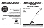
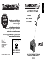
STOP
ARRÊT
ALTO
Electric
Snow Thrower
For problems or questions, DO NOT return
this product to the store. Contact your
Customer Service Agent .
31A-020-900
En cas de problèmes ou pour des questions,
NE PAS retourner ce produit au point de vente. S'adresser
au préposé du Service à la clientèle en composant.
Para problemas o preguntas, NO devolver este producto a la tienda
Contacte a su Agente de Servicio al Cliente.
U.S.A. Imported by:
MTD LLC
P.O. Box 361131
Cleveland, OH 44136-0019
For Consumer Assistance Please Call
L'Aide Du Consommateur Necessitez S'il Vous Plait
Para La Ayuda Del Consumidor Llame Por Favor
Canada Imported by / Importé par:
MTD PRODUCTS LIMITED
97 Kent Avenue
Kitchener, ON
CANADA N2G 4J1
U.S.A. 1-866-747-9816
CANADA 1-800-668-1238
Made in China / Fabriquè à China / Hecho en China
IMPORTANT: READ SAFETY RULES
AND INSTRUCTIONS CAREFULLY
P/N 6096-MD2301
PRINTED IN CHINA
English
Operator’s Manual
TABLE OF CONTENTS
RULES FOR SAFE OPERATION
Rules for Safe Operation
Pages 2-7
Specifications
Page 12
Operating Instructions
Page 8-9
Parts List
Page 13
Maintenance Instructions
Pages 10-11
Notes
Page 14
Troubleshooting
Page 12
Manufacturer’s Limited Warranty Page 15
The purpose of safety symbols is to attract your attention to possible dangers. The safety symbols, and their
explanations, deserve your careful attention and understanding. The safety warnings do not by themselves
eliminate any danger. The instructions or warnings they
give are not substitutes for proper accident prevention
measures.
SYMBOL
SYMBOL
MEANING
Failure to obey a
safety warning will
result in serious injury to yourself or to others. Always follow the safety precautions to
reduce the risk of fire, electric shock and
personal injury.
DANGER:
MEANING
Failure to obey a
WARNING: safety warning can
Indicates
danger,
warning or
caution. Attention is required in order to
avoid serious personal injury. May be used
in conjunction with other symbols or pictographs.
SAFETY ALERT:
result in injury to yourself and others.
Always follow the safety precautions to
reduce the risk of fire, electric shock and
personal injury.
Failure to obey a
safety warning may
result in property damage or personal injury
to yourself or to others. Always follow the
safety precautions to reduce the risk of fire,
electric shock and personal injury.
CAUTION:
NOTE: Advises you of information or instructions vital to
the operation or maintenance of the equipment.
Read the Operator’s Manual(s) and follow all warnings
and safety instructions.
Failure to do so can result in serious injury to the
operator and/or bystanders.
FOR QUESTIONS, CALL 1-800-668-1238
• IMPORTANT SAFETY INSTRUCTIONS •
READ ALL INSTRUCTIONS
• Carefully inspect the area before starting the unit.
Remove all debris and hard or sharp objects such as
glass, wire, etc.
BEFORE OPERATING
When using the
unit, please read
safety rules instructions before operating
the unit in order to ensure the safety of the
operator and any bystanders. Please keep
these instructions for later use.
• Clear the area of children, bystanders, and pets. At a
minimum, keep all children, bystanders, and pets outside a 50 feet (15m.) radius; there still may be a risk to
bystanders from thrown objects. If you are approached,
stop the unit immediately.
WARNING:
• Read the instructions carefully. Be familiar with the
controls and proper use of the unit.
• Do not operate this unit when tired, ill or under the
influence of alcohol, drugs or medication.
• Children must not operate the unit. Teens must be
accompanied and guided by an adult.
• All guards and safety attachments must be installed
properly before operating the unit.
• Inspect the unit before use. Replace damaged parts.
Make sure all fasteners are in place and secure.
Replace parts that are cracked, chipped or damaged in
any way. Do not operate the unit with loose or damaged parts.
1
2
RULES FOR SAFE OPERATION
MINIMUM WIRE GAUGE RECOMMENDATIONS
PLEASE READ - SAVE THESE
INSTRUCTIONS
VOLTS
When using an electrical appliance, basic precautions
should always be followed to assure maximum safety and
optimum performance. Read this manual before assembling and operating this appliance. Failure to comply with
instructions may result in electrical shock, burns, fire, or
personal injury.
120
3.
4.
5.
6.
WIRE SIZE
REQUIRED
18 A.W.G.*
16 A.W.G.*
16 A.W.G.*
Table 1
(1). When using the appliance, an extension cord of adequate size must be used for safety and to prevent
loss of power and overheating.
(2). The extension cord must be specifically intended for
outdoor use and marked “SJ” or “SJT” and with the
suffix “WA”. In Canada, the extension cord must be
marked “SFTW”.
(3). Inspect extension power cord for loose or exposed
wires and damaged insulation. If damaged, replace
before using appliance.
DO NOT ABUSE CORD - Never carry appliance by
cord or pull cord to disconnect from outlet. Keep cord
clear of operator and obstacles at all times. Do not
expose cord to heated surfaces, oil or water. Do not
pull cord around sharp edges, corners or close door
on cord.
NO SERVICEABLE PARTS INSIDE - Your dou7.
ble insulated appliance has no serviceable parts
inside. Do not attempt to repair it yourself. For service information, contact the Yard Machines Product
Service Department listed on the back cover of this
User Manual.
8. RISK OF EYE INJURY - Always wear goggles or
other suitable eye protection when operating your
snow thrower. Always keep bystanders at a safe distance.
9. DRESS PROPERLY - Always wear long pants, shoes
and gloves. Do not wear loose clothing, jewelry, Wear
rubber boots when operating snow mover.
10. KEEP AREA CLEAR - Keep everyone, especially
children and pets away from the area of operation 50
feet (15m). Turn off unit immediately if you are
approached. Never allow children to operate the
appliance to be used as a toy or to run unattended at
any time.
11. Do not use on graveled surface unless the snow
mover is adjusted for such a surface in accordance
with the operator’s manul.
12. KEEP CHILDREN AWAY - All visitors should be kept
a safe distance from work area.
TO REDUCE THE RISK OF ELECTRIC
SHOCK, BURNS, FIRE OR PERSONAL
INJURY:
2.
EXTENSION CORD
LENGTH
25 feet / 7.5m
50 feet / 15m
100 feet / 30m
*American Wire Gauge
WARNING
1.
RULES FOR SAFE OPERATION
FOLLOW ALL SAFETY INSTRUCTIONS listed in
this manual before/during operation of this snow
thrower.
TO REDUCE THE RISK OF ELECTRIC SHOCK this
equipment has a polarized plug (one blade is wider
than the other). This plug will fit in a polarized extension cord only one way. If the plug does not fit fully in
the extension cord, reverse the plug. Do not change
the plug in any way.
INSPECT UNIT FOR DAMAGE to the housing or
plug. Keep all fasteners tight. Do not use if the trigger
does not turn the unit off properly. Never use unit if
cord or plug has been damaged, the motor or unit
itself is not working as it should or has been dropped,
damaged, left outdoors or dropped in water. Never
operate with any air opening blocked. Keep air openings free of debris that may reduce air flow. Replace
damaged parts that are chipped, cracked or damaged in any way.
DOUBLE INSULATED to help protect against
electric shock. Double insulation construction
consists of 2 separate “layers” of electric insulation.
Appliances built with this insulation system are not
intended to be grounded. As a result, the extension
cord used with your unit can be plugged into any
conventional 120 volt electrical outlet. Normal safety
precautions must be observed when operating an
electrical appliance. The double insulation system is
only for added protection against injury resulting from
a possible internal electrical insulation failure.
When the double insulation symbol (a square within a
square) is used as the only marking to identify a unit
as being double insulated, the symbol shall be
defined in the instruction manual.
EXTENSION CORD - Use only with an extension
cord intended for outdoor use. Match wire gauge to
the cord length. See table below. A 2-wire cord without a ground connection may be used since this
appliance is double insulated. If in doubt of proper
wire size, use the next heavier gauge. Please note
that the smaller the gauge number, the heavier the
cord.
3
WHILE OPERATING
13. Wear rubber boots when operating the snow mover.
14. Cautionary statements regarding the use of proper
clothing and footwea during operations to reduce the
risk of injury that may be caused by flying debris.
15. Operation of the snow mover in the hand-held position is unsafe, except in accordance with the special
instructions for such use provided in the operator’s
manual.
16. WARNING - This snow mover should be grounded
while in use to protect the operator form electric
shock. To prevent electric shock use only with an
extension cord suitable for outdoor use.
17. EXTENSION CORD - To prevent disconnection of
snow mover cord from the extension cord during
operation.
18. AVOID ACCIDENTAL STARING - Don’t carry
plugged - in snow mover with finger on switch. Be
sure switch is off when plugging in.
19. If cord is damaged in any manner while plugged in,
pull extension cord from wall receptacle.
20. DON’T ABUSE CORD - Never carry snow mover by
cord or yank it to disconnect from receptacle. Keep
cord from heat, oil, and sharp edges.
21. Keep hands away from moving parts.
22. Keep guards in place and in working order.
23. DON’T FORCES SNOW MOVER - It will perform
better and safer at the rate for which it was
designed.
24. DON’T OVERREACH - Keep proper footing and
balance at all times.
25. If the snow mover strikes a foreign object follow
these steps:
i) Stop snow mover.
ii) Inspect for damage.
iii) Repair any damage before restarting and operating the snow mover.
26. DISCONNECT SNOW MOVER - Disconnect the
snow mover from the power supply when not in use,
before servicing, when changing accessories, and
the like.
27. STORE IDLE SNOW MOVERS INDOORS - When
not in use, snow movers should be stored indoors in
dry, locked-up place - out of reach of children.
28. MAINTAIN SNOW MOVERS WITH CARE - Follow
instructions for lubricating and changing accessories.
29. Don’t use any other accessory or attachment might
incrase the risk of injury.
1.
2.
3.
4.
5.
6.
7.
8.
9.
10.
11.
12.
13.
14.
15.
16.
17.
18.
19.
20.
21.
4
Walk, never run.
Be sure the snow thrower is not in contact with anything before staring the unit.
Stay away from the discharge opening at all times.
Keep face, hands, and feet away from concealed
moving or rotating parts.
Be attentive when using the snow thrower, and stay
alert for holes in the terrain and other hidden hazards
or traffic.
Do not use on a gravel surface or crushed rock surfaces. Use extreme caution when crossing
gravel/crushed rock drives, walks, or roads.
Never clear snow from steep slopes.
Never attempt to use the snow thrower on a roof or
any steep, inclined, slippery surfaces.
Never operate snow thrower without proper guards,
plates or other safety protective devices in place.
Never operate the snow thrower near glass enclosures, automobiles, trucks, window wells, dropoffs,
etc. without proper adjustment of the snow discharge
angle. Keep children and pets away.
Don’t force or overload the snow thrower. The snow
thrower will perform at its best and safest when it is
run at the rate for which it was designed.
Never direct discharge towards people or allow anyone in front of the unit while operating.
Wear safety glasses or goggles that are marked as
meeting ANSI Z87.1 standards, and ear/hearing protection when operating this unit.
Use the unit only in daylight or good artificial light.
Avoid accidental starting. Remain in the starting position whenever starting the unit. The operator and unit
must be in a stable position while starting.
Use the right tool. Only use this tool for the purpose
intended.
Do not overreach. Always keep proper footing and
balance.
Always hold the unit with both hands when operating.
Keep a firm grip on handles or grips.
Keep hands, face, and feet at a distance from all
moving parts. Do not touch or try to stop the rotor
when it is rotating.
If the rotor will not rotate freely due to frozen ice, thaw
the unit thoroughly before attempting to operate it
under power.
Keep the rotor clear of debris.
Never attempt to clear the rotor with the motor running. Turn the motor off first and unplug the extension
cord.
RULES FOR SAFE OPERATION
EXPLANATION OF NOTE, WARNING, and
WARRANTY SYMBOL
22. Keep clothing and body parts away from the rotor.
23. Always stop the motor when clearing snow is delayed
or when walking from one location to another.
24. Disengage power to the rotor when snow thrower is
transported or not in use.
25. After striking a foreign object, turn the unit off and
inspect the snow thrower from damage. Unplug the
unit. Repair damage before restarting and operating
the unit.
26. If the unit should start to vibrate abnormally, stop the
unit and check immediately for the cause. Vibratioin
is generally a warning of trouble.
27. Stop the motor and unplug the unit whenever you
leave the operating position, before unclogging the
rotor or discharge vanes, and when making any
repairs, adjustments, or inspections.
28. Use only original equipment manufacturer replacement parts and accessories for this unit. These are
available from your authorized service dealer. Use of
any unauthorized parts or accessories could lead to
serious injury to the user or damage to the unit, and
void your warranty.
29. Do not use the unit in the hand held position. Do not
pick up the unit when it is powered and running. The
unit is designed to travel along the ground.
1.
2.
3.
4.
3.
4.
5.
6.
SAFETY AND INTERNATIONAL SYMBOLS
This operator's manual describes safety and international symbols and pictographs that may appear on this product.
Read the operator's manual for complete safety, assembly, operating and maintenance and repair information.
SYMBOL
SYMBOL
MEANING
• SAFETY ALERT SYMBOL
WARNING : Unplug unit if cord is
damaged or cut.
Indicates danger, warning, or caution.
May be used in conjunction with
other symbols or pictographs.
• THROWN OBJECTS AND ROTATING CUTTER CAN CAUSE SEVERE
INJURY
• WARNING - READ OPERATOR'S
MANUAL
WARNING : Small objects can be
propelled at high speed, causing
injury. Keep away from the rotating
rotor.
Read the Operator’s Manual(s) and
follow all warnings and safety
instructions. Failure to do so can
result in serious injury to the operator
and/or bystanders.
• KEEP BYSTANDERS AWAY
WARNING : Keep all bystanders, at
least 50 feet (15m) from the operating
area.
• SPINNING ROTOR CAN CAUSE
SEVERE INJURY
WARNING: Keep hands, feet, and
clothing away from the discharge
area. Do not step in front of the unit,
or use hands to clean the rotor area.
Be sure to secure the unit while transporting.
Store the unit in a dry area, locked up or up high to
preventunauthorized use or damage, out of the reach
of children.
Never douse or squirt the unit with water or any other
liquid. Keep handles dry, clean and free from debris.
Clean after each use.
If the labels on the unit become defaced or start lifting off, contact your authorized service dealer.
Keep these instructions. Refer to them often and use
them to instruct other users. If you loan someone this
unit, also loan them these instructions.
Maintain snow movers with care. Follow instructions
for lubricating and changing accessories.
5
MEANING
• ELECTRIC SHOCK HAZARD
SAVE THESE INSTRUCTIONS
OTHER SAFETY WARNINGS
1.
2.
A NOTE is used to convey additional information, or
highlight a particular explanation, or to expand a step
instruction.
A WARNING identifies a procedure which, if not
undertaken or if improperly done, can result in a serious personal injury or damage to the unit and/or
both.
(WARRANTY SYMBOL) serves notice that
unless instructions or procedures are followed, any
damage will void the warranty and repairs will be at
owner’s expense. Service other than user maintenance should be performed by a Yard Machines
Authorized Service Center. Damage or conditions
caused by improper maintenance practices which
render this product inoperable will void the manufacturer’s warranty.
FOR WARRANTY OR SERVICE contact the nearest
Yard Machines Authorized Service Center by calling
800# on back cover.
RULES FOR SAFE OPERATION
6
RULES FOR SAFE OPERATION
OPERATING INSTRUCTIONS
REAR
HANDLE
LOCK-OFF
BUTTON
CONNECT THE CORD
POSITIONING THE ASSIST HANDLE
1.
1.
2.
2.
3.
ON/OFF TRIGGER
CORD RETAINER
ASSIST
HANDLE
4.
5.
Ensure the cord is NOT plugged into a receptacle
before this procedure.
Make a loop with 8″ - 10″ (20 - 25cm) of the end of the
extension cord.
Place the loop into the slot (A) under the rear handle
and lock into place on the cord retainer (B) as shown
in Figure 1.
Plug the extension cord into the electrical receptacle
in the snow thrower handle.
Plug the extension cord into a receptacle ONLY when
you are ready to operate the snow thrower.
3.
Loosen the knob (A) on the assist handle (B). (Fig. 3)
Adjust the assist handle to an angle that is comfortable to you.
Tighten the knob on the assist handle.
B
PLUG FOR
EXTENSION CORD
A
A
Fig. 3
B
STARTING AND STOPPING
To start the snow thrower, push the button (A) on the side
of the handle grip and squeeze the trigger (B). To stop the
product, release the trigger. (Fig. 4)
NOTE: When properly started, the safety button will stay
engaged when holding the trigger. When the trigger is
released, the unit stops and the safety button will disengage.
ADJUSTMENT RING
Fig. 1
ADJUST SHAFT LENGTH
ADJUSTABLE
SHAFT
1.
2.
3.
Loosen the adjustment ring (A) by rotating the ring
clockwise.
Adjust the shaft to a height that is comfortable to you.
Tighten the adjustment ring (A) by rotating the ring (A)
counter clockwise. (Fig. 2)
A
AIR OPENINGS
MOTOR HOUSING
B
A
Fig. 4
BELT CASE COVER
Fig. 2
SCRAPER
ROTOR
7
8
OPERATING INSTRUCTIONS
MAINTENANCE INSTRUCTIONS
OVERLOAD PROTECTION SWITCH
TIPS FOR BEST SNOW THROWING RESULTS
SERVICING THE UNIT
This unit is equipped with an overload protection switch to
protect the circuit (that the unit is plugged into) from short
circuit overloads.
If the switch pops out:
1. Release the bail and allow the unit to stop and cool for
a minute.
2. Press the overload switch (A) to reset. Resume operation. (Fig. 5)
If the switch pops again shortly after the first time:
1. Allow the unti to cool for 15 to 30 minutes.
2. After the unit has cooled, press the overload switch to
reset. Resume operation.
If the switch does not stay in or if it continues to pop out
during operation, take the unit to an autorized service dealer for repair.
1.
Extreme care and knowledge of the system is required
when servicing this unit. Service should be performed by
qualified service personnel only. Replacement parts for this
unit must be identical to the parts they replace. Refer any
repair to an authorized service dealer.
2.
For the most efficient snow throwing, throw snow
downwind.
Slightly overlap each swath you make. (Fig. 6)
Ax7
B
INSPECTING/REPLACING THE DRIVE BELT
When servicing the unit, use only original equipment manufacturer replacement parts. Inspect the drive belt once a
year or every 50 hours of operation, whichever comes first,
for wear. If the drive belt needs to be replaced, use the following instructions.
Fig. 7
To avoid serious
personal injury,
turn off the unit and allow it to cool. Unplug
the unit before you perform any maintenance.
WARNING:
D
1.
Fig. 6
A
Fig. 5
OPERATING THE SNOW THROWER
1.
2.
3.
Start the unit according to the starting instructions.
The depth and weight of the snow governs the forward
speed.
Push the unit so that it rides on the scraper.
Make sure the power cord is attached to the cord
retainer. The power cord should trail to the side of the
operator.
9
Remove the 7 screws (A) from the belt case cover (B)
using a #T20 torx bit or flat blade screwdriver. (Fig. 7)
2. Remove the flange lock nut (C) and remove the 3
screws (D) from the belt case cover (E) using a #T20
Torx bit or flat blade screwdriver. (Fig. 8)
3. Pull the belt tensioner (F) away from the drive pulley
(G). Remove the damaged or broken belt (H) from the
driven pulley (I) and drive pulley inside of the housing.
Discard appropriately. (Fig. 9)
4. Loop the new belt around the drive pulley and driven
pulley (Fig. 8). Pull the belt tensioner (idler arm) away
from the drive pulley to install the belt around the drive
pulley.
NOTE: Make sure the washer is still in place on the driven
pulley shaft prior to reinstalling the belt case cover.
5. Reinstall the flange lock nut. Torque the nut to 50-100
in• lb (90-11.2 N•m) and reinstall the 3 screws. Torque
all screws to 18-23 in• lb (20-2.5 N•m).
6. Reinstall the cover with the 7 screws. To make installation easier, place the narrow part of the cover into
the recess of the housing. Install the top 2 screws,
then push the rest of the cover down into the recess
and over the rotor shaft. Toque all 7 screws to 18-23
in• lb (20-2.5 N•m)
NOTE: If the flange lock nut is damaged, do not replace it
with a standard nut. Replace only with an original equipment manufacturer replacement part.
C
E
Fig. 8
F
G
H
I
Fig. 9
10
MAINTENANCE INSTRUCTIONS
REPLACING THE PLATE
CLEANING
Use only original equipment manufacturer replacement
parts.
To avoid serious
personal injury,
always turn your unit off and unplug it
before you clean or service it.
WARNING:
To avoid serious
personal injury,
always turn your unit off and unplug it
before you perform maintenance.
WARNING:
1.
2.
3.
4.
Use a small brush to clean off the outside of the unit. Do not
use strong detergents. Household cleaners that contain
aromatic oils such as pine and lemon, and solvents such as
kerosene, can damage plastic housing or handle. Wipe off
any moisturer with a soft cloth.
Place the unit on the ground or on a work bench.
Position the unit so the vanes and rotor are facing up.
Beneath the rotor, locate the 3 screws (A) securing
the plate (B) to the housing. Remove them using a
#T20 Torx bit or flat blade screwdriver. (Fig. 10)
Remove the scraper and discard it appropriately.
The new scraper will snap into place. Once in place,
attach it to the unit by reinstalling the 3 screws.
TRANSPORTING
1.
2.
Secure the unit while transporting.
To move the unit, grasp it by the top and middle front
handles.
TROUBLESHOOTING
UNIT WILL NOT START
CAUSE
ACTION
Unit is unplugged
Check cord to make sure it is plugged into an electrical
outlet
Trigger lock button or trigger were improperly actuated
Press in trigger lock button, hold it, and press in trigger
Overload protection switch has popped out
Push it in and follow the starting instructions
MOTOR IS ON, BUT ROTOR WILL NOT TURN
CAUSE
ACTION
Belt is damaged
Replace the belt, according to inspecting/Replacing the
driver belt
UNIT LEAVES A THIN LAYER OF SNOW ON PLOWED SURFACES
CAUSE
ACTION
Scraper is worn
Replace the scraper
If further assistance is required, contact your authorized service dealer
A
SPECIFICATIONS
B
Fig. 10
Motor type . . . . . . . . . . . . . . . . . . . . . . . . . . . . . . . . . . . . . . . . . . . . . . . . . . . . . . . . . . . . . . . . . . . .A. C. 120 Volts Electric
Amperage . . . . . . . . . . . . . . . . . . . . . . . . . . . . . . . . . . . . . . . . . . . . . . . . . . . . . . . . . . . . . . . . . . . . .7.5 Amps
STORAGE
1.
2.
3.
4.
clearing Width . . . . . . . . . . . . . . . . . . . . . . . . . . . . . . . . . . . . . . . . . . . . . . . . . . . . . . . . . . . . . . . . .12.5” (318mm)
Allow the motor to cool before storing.
Store the unit locked up to prevent unauthorized use
or damage.
Store the unit in a dry, well-ventilated area.
Store the unit out of the reach of children.
Intake Height . . . . . . . . . . . . . . . . . . . . . . . . . . . . . . . . . . . . . . . . . . . . . . . . . . . . . . . . . . . . . . . . . .6” (152mm)
Weight . . . . . . . . . . . . . . . . . . . . . . . . . . . . . . . . . . . . . . . . . . . . . . . . . . . . . . . . . . . . . . . . . . . . . . .15 lbs
11
12
PARTS LIST
NOTES
1
45
2
3
4
5
6
44
7
8
48
51
53
46
6
10
11
43
9
12
42
6
47
13
52
14
15
6
41
54
40
39
16
17
18
38
50
37
19
36
49
6
35
34
20
21 22
23
24
16
25
26
27 28
29
17
30
55
31
32
33
No.
Parts No.
Description
No.
Parts No.
Description
1
2
3
4
5
6
7
8
9
10
11
12
13
14
15
16
17
18
19
20
21
22
23
24
25
26
27
28
6022-MD2301
6068-MD2301
6134-MD2301
6196-MD2302
6196-MD2301
6SGEBB04-18
6070-MD2301
6037-MD2301
6010-MD2301
6067-MD2301
6129-MD2301
6131-MD2301
6187-MD2301
6099-MD2301
6017-MD2301
6014-MD2301
6148-MD2301
6250-MD2301
6100-MD2302
6WFB-04
6200-MD2301
6064-MD2301
6111-MD2302
6024-MD2301
6004-MD2302
6DB-620301
6004-MD2301
6137-MD2301
SWITCH
HANDLE RIGHT
KNOB
ASSIST HANDLE
ASSIST HANDLE
SCREW
PLUG PIPE
TUBE
SPRING CODE
HOUSING TOP
PIPE
SPOOL
FIXED PLATE
MOTOR
COVER RIGHT
WASHER
SLEEVE
BLADE
PLATE
WASHER
PLATE
MAIN BODY
SHAFT
SPRING
HOLDER BOTTOM
BEARING
HOLDER TOP
PULLEY
29
30
31
32
33
34
35
36
37
38
39
40
41
42
43
44
45
46
47
48
49
50
51
52
53
54
55
6137-MD2302
6149-MD2301
6072-MD2301
9NAC-08
6017-MD2302
6SDABB04-20
6WFB-04-12
9WFB-08-13
9SKKBY10/24-0.5
6014-MD2302
6189-MD2301
6078-MD2301
6067-MD2302
6068-MD2302
6SXDZ-06-100
6272-MD2301
6041-MD2301
6010-MD2304
6032-070-01
6041-610201
6014-MD2303
6139-MD2302
6059-MD2304
6SGEBB04-35
6SDABB3.5-18
6183-MD2301
6014-211901
PULLEY ACTIVE
STRAP
FIXED PLATE
NUT
COVER LEFT
SCREW
WASHER
WASHER
SCREW
WASHER
WASHER
CAP
HOUSING BOTTOM
HANDLE LEFT
SCREW
PROTECT SWITCH
CONNECTOR
WIRE ASS'Y
BAND, PLASTIC
TERMINAL
WASHER
PLASTIC WASHER
PIPE
SCREW
SCREW
GASKET
WASHER
13
14
STOP
ARRÊT
ALTO
Electric
Snow Thrower
For problems or questions, DO NOT return
this product to the store. Contact your
Customer Service Agent .
31A-020-900
En cas de problèmes ou pour des questions,
NE PAS retourner ce produit au point de vente. S'adresser
au préposé du Service à la clientèle en composant.
Para problemas o preguntas, NO devolver este producto a la tienda
Contacte a su Agente de Servicio al Cliente.
U.S.A. Imported by:
MTD LLC
P.O. Box 361131
Cleveland, OH 44136-0019
For Consumer Assistance Please Call
L'Aide Du Consommateur Necessitez S'il Vous Plait
Para La Ayuda Del Consumidor Llame Por Favor
Canada Imported by / Importé par:
MTD PRODUCTS LIMITED
97 Kent Avenue
Kitchener, ON
CANADA N2G 4J1
U.S.A. 1-866-747-9816
CANADA 1-800-668-1238
Made in China / Fabriquè à China / Hecho en China
IMPORTANT: READ SAFETY RULES
AND INSTRUCTIONS CAREFULLY
P/N 6096-MD2301
PRINTED IN CHINA
English
Operator’s Manual