1
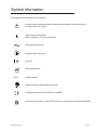
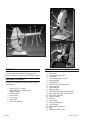
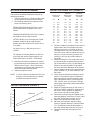
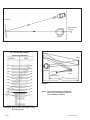
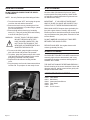
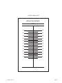
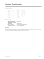
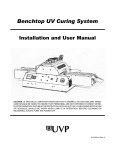
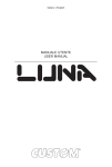
®
LongLife
P-O-C
User’s Guide
©2009 Reichert, Inc. Reichert is a registered trademark of Reichert, Inc.
The information contained in this document was accurate at time of publication. Speciications subject to change without notice. Reichert, Inc.
reserves the right to make changes in the product described in this manual without notice and without incorporating those changes in any
products already sold.
Federal law restricts this device to sale by or on the order of a physician.
ISO 9001 Certiied – Reichert products are designed and manufactured under quality processes meeting ISO 9001 requirements.
No part of this publication may be reproduced, stored in a retrieval system, or transmitted in any form or by any means, electronic, mechanical, recording, or otherwise, without the prior written permission of Reichert, Inc.
Page 2
12084-101 Rev. D
Table of Contents
Warnings & Cautions ............................................................................................. 4
Symbol Information................................................................................................ 5
Package Contents ................................................................................................. 6
Instrument Components ........................................................................................ 6
Installation And Alignment ..................................................................................... 7
Slide Selection ....................................................................................................... 9
Bulb Life................................................................................................................. 9
Filament Alignment ................................................................................................ 9
Internal Fuse.......................................................................................................... 9
Bulb Replacement ............................................................................................... 10
Slide Cleaning ..................................................................................................... 10
Screen Cleaning .................................................................................................. 10
Accessory/Part Numbers ..................................................................................... 10
Symbol Information.............................................................................................. 10
Letter Sizing Chart (feet) .................................................................................... 11
Letter Sizing Chart (meters) ............................................................................... 12
General Specifications......................................................................................... 13
Classifications and Standards ............................................................................. 14
Warranty .............................................................................................................. 15
12084-101 Rev. D
Page 3
Warnings & Cautions
Reichert, Inc. (Reichert) is not responsible for the safety and reliability of this
instrument when:
• Assembly, disassembly, repair, or modiication is made by unauthorized dealers or persons
• Instrument is not used in accordance with this User’s Guide
WARNING: AN INSTRUCTION THAT DRAWS ATTENTION TO RISK OF INJURY OR DEATH.
WARNING: ANY REPAIR OR SERVICE TO THE LONgLIfE POC MUST BE PERfORMED BY EXPERIENCED PERSONNEL
OR DEALERS THAT ARE TRAINED BY REICHERT SO THAT CORRECT OPERATION Of THE LONgLIfE POC IS MAINTAINED.
WARNING: DO NOT PLACE fINgERS INTO THE OPENINg SURROUNDINg THE NOSEPIECE.
WARNING: THIS INSTRUMENT IS NOT SUITABLE fOR USE IN THE PRESENCE Of fLAMMABLE ANESTHETIC MIXTURES, SUCH AS OXYgEN OR NITROUS OXIDE.
CAUTION: AN INSTRUCTION THAT DRAWS ATTENTION TO THE RISK
OF DAMAGE TO THE PRODUCT.
CAUTION: DO NOT USE SOLVENTS OR STRONg CLEANINg SOLUTIONS ON ANY PART Of THIS INSTRUMENT AS
DAMAgE TO THE UNIT MAY OCCUR. SEE MAINTENANCE SECTION fOR DETAILED CLEANINg INSTRUCTION.
CAUTION: USE Of ALCOHOL ON THE LIQUID CRYSTAL DISPLAY (LCD) MAY CAUSE DAMAgE TO THE DISPLAY. SEE
MAINTENANCE SECTION fOR DETAILED CLEANINg INSTRUCTION.
CAUTION: THIS INSTRUMENT IS NOT SUITABLE fOR USE IN THE PRESENCE Of fLAMMABLE ANESTHETIC MIXTURES SUCH AS OXYgEN OR NITROUS OXIDE.
CAUTION: PORTABLE AND MOBILE Rf COMMUNICATIONS EQUIPMENT CAN AffECT MEDICAL ELECTRICAL EQUIPMENT.
CAUTION: THE INTERNAL CIRCUITRY Of THE INSTRUMENT CONTAINS ELECTROSTATIC DISCHARgE SENSITIVE DEVICES (ESDS) THAT MAY BE SENSITIVE TO STATIC CHARgES PRODUCED BY THE HUMAN BODY. DO NOT REMOVE
THE COVERS WITHOUT TAKINg PROPER PRECAUTIONS.
CAUTION: MEDICAL ELECTRONIC EQUIPMENT NEEDS SPECIAL PRECAUTIONS REgARDINg EMC AND NEEDS TO
BE INSTALLED AND PUT INTO SERVICE ACCORDINg TO THE EMC INfORMATION PROVIDED IN THE ACCOMPANYINg
DOCUMENTS.
CAUTION: THIS INSTRUMENT IS NOT TO BE USED NEAR HIgH-fREQUENCY EMITTINg SURgICAL EQUIPMENT.
Page 4
12084-101 Rev. D
Symbol Information
The following symbols appear on the instrument.
Caution symbol indicating important operating and maintenance instructions that are
included in this User’s Guide.
Type B Product Classiication.
Class 1 Equipment, Continuous Operation.
Alternating Current Power.
Protective Earth Connection.
ON / OFF.
Date of Manufacture.
[REF]
Catalog Number.
Waste of Electrical and Electronic Equipment.
Compliance to Medical Device Directive 93/42/EEC.
Authorized to mark given by Intertek ETL Semko for conformance with electrical standards.
12084-101 Rev. D
Page 5
13
14
1
11
12
15
10
2
16
17
3
18
9
4
6
7
19
8
21
20
5
PRODUCT
This manual should be used in reference to the
Reichert LongLife™ Project-O-Chart® Model 12084.
PACKAGE CONTENTS
Contents of the shipping container should include
the following:
1 LongLife P-O-C™ Head
(See Instrument Components for
detailed listing.)
1 Objective Tube
1 Power Cord
1 Dust Cover
1 Cross Slide
1 Instruction Manual
Page 6
INSTRUMENT COMPONENTS
1.
2.
3.
4.
5.
6.
7.
8.
9.
10.
11.
12.
13.
14.
15.
16.
17.
18.
19.
20.
21.
Rear Cover
Horizontal Line Selector
Cross Slide
Vertical Slide Motion Control
Mounting Knob
Support Barrel
Variable Focus Objective Tube
Outer Objective
Inner Objective
Retaining Ring
Outer Objective Tube Locking Screw
Inner Objective Tube Locking Screw
Rear Cover Fastener
ON/OFF Switch
AC Inlet
Power Cord
Yoke (Not Supplied)
Yoke Screws
Bulb Relector Housing
Bulb
Relector Housing Screw
12084-101 Rev. D
INSTALLATION AND ALIGNMENT
The projector should be installed according to the
following procedures:
1. If using a wall mount, it is best to locate a wall
stud to support the projector head’s weight.
2. The following distances are important in the
setup of a refracting room:
REFRACTING DISTANCE (RD) This is equal
to the distance from the patient’s eye to the
screen.
PROJECTION DISTANCE (PD) This is equal to
the distance from the slide to screen.
LETTER HEIGHT (LH) The height of a 20/200
character should be equal to the refraction
distance times the tangent of 50 minutes of arc
or .014545.
LH (inches or mm) = RD (inches or mm) x
.014545
For example, a refracting distance of 240 inches (20 feet) will require a letter height of 3.49
inches (240 inches x .014545 = 3.49 inches)
3. Determine the refracting distance by measuring the distance from the patient to the screen.
Please refer to Figures 1 and 2 which show
combinations of refraction and projection distances achievable with this system.
4. Install the projector screen.
NOTE: To ensure maximum performance from your
projector, we recommend that you always
use Reichert projection screens.
PROJECTION RANGE (FIGURE 1)
Refraction Distance (FT.)
30
Maximum
25
20
Minimum
15
10
5
0
8 9 10 11 12 13 14 15 16 17 18 19 20
PROJECTION RANGE LIST (FIGURE 2)
PROJECTION
DISTANCE
MINIMUM
REFRACTING
DISTANCE
MAXIMUM
REFRACTING
DISTANCE
FT
M
FT
M
FT
M
8
9
10
11
12
13
14
15
16
17
18
19
20
2.5
2.8
3.1
3.4
3.7
4.0
4.3
4.6
4.9
5.2
5.5
5.8
6.2
6.6
7.7
8.7
9.8
10.9
11.9
13.0
14.1
15.1
16.2
17.3
18.3
19.4
2.0
2.4
2.7
3.0
3.4
3.7
4.0
4.3
4.6
4.9
5.3
5.6
6.0
9.9
11.5
13.0
14.5
16.1
17.6
19.1
20.7
22.2
23.7
25.3
26.8
28.3
3.0
3.5
4.0
4.5
5.0
5.4
5.9
6.4
6.8
7.3
7.8
8.2
8.7
5. Insert the variable focus objective tube into the
support barrel. Do not fully tighten the outer
objective lock screw (11) to allow for inal focus adjustments. Check the in and out movement of the outer and inner objective tubes (8)
and (9). It may be necessary to loosen lock
screws (11) and (12) to provide freedom of
movement.
6. Attach the LongLife P-O-C head to the mount
by unscrewing the mounting knobs (5) inserting the head into the yoke (17) and reitting the
knobs into the proper position. Fully tighten
the knobs after inal adjustment of the system.
7. Insert a character slide into the instrument and
project a 20/200 “E” (or other character) onto
the screen.
8. Check the three dimensional alignment of the
system. This projection system is optimized
when the projector screen is angled to direct
light to the patient’s head. Turn the projector
“ON”. Place a mirror on the screen. The light
should project where the patient’s head would
be. See Figure 3.
9. Adjust the image positioning on the screen. It
may be necessary to adjust the projector and
the screen. Secure projector by tightening
yoke screws (18) and mounting knobs.
10. Determine the proper letter size based on the
refracting distance used. Refer to Figure 4 and
the Letter Sizing Chart on pages 11 & 12.
11. Attach Letter Sizing Chart to the screen.
12. Move the inner and outer objective tubes,
usually in opposite directions, until the 20/200
“E” is in sharp focus and ills the bracket on
the Letter Sizing Chart as shown in Figure 4.
13. Tighten the inner and outer objective lock
screws.
Projection Distance (FT.)
12084-101 Rev. D
Page 7
Screen
Spot of Light
on Wall
Patient
FIGURE 3
Screen
LETTER SIZING CHART
REFRACTING DISTANCE
8.53
8.23
7.92
7.62
7.32
7.01
6.71
6.40
6.10
5.79
5.49
4.27
26
25
24
Patient
6"x 6"
Mirror
23
22
21
Project-O-Chart
20
8'.0"
19
17
4.57
15
3.96
13
18
16
12'.0"
FIGURE 5
14
3.66
NO
T
28
27
5.18
TO
4.88
Mirror
FEET
SC
AL
E
METERS
12
3.35
11
2.74
9
2.14
7
3.05
10
2.44
8
NOTE: Care should be taken in alignment
when using vectographic slides to
insure optimum contrast.
FIGURE 4 (Not to Scale - See pages 11 & 12
for sizing charts)
Page 8
12084-101 Rev. D
NOTE: To obtain longer refracting distances in small
rooms, a mirror system can be used. A high
quality front-surface mirror is required. See
Figure 5 as an example of an arrangement
for a short room with full 20 foot refracting
distance.
SLIDE SELECTION
The cross slide (3) contains three apertures which
index into position in front of any frame of characters
projected from the acuity slide. The large aperture
is centrally located on the slide. In this position,
an entire frame of characters is projected onto the
screen.
By moving the slide to the left or right of the central
position, either the vertical line aperture or the red
and green ilters (Duochrome Test) will be moved into
position for projection.
To attach the cross slide, unscrew one of the knobs
and insert the slide into the slot, through the projector. When inserting the cross slide, be certain that the
frame holding the ilters faces towards the rear of the
instrument and that the index notches face upward.
The cross slide, as well as the horizontal line selector
(2), may be operated from either the left or the right
side of the instrument. When the horizontal line selector is used with the vertical aperture of the selector
slide, projection of single characters is possible.
BULB LIFE
The LongLife P-O-C uses the 11143 Halogen Bulb
(20) to produce a superb combination of brightness
and long bulb life.
You can maximize the bulb’s useful life by following
these guidelines:
1. After turning the unit “ON”, use it for at least one
hour.
2. If you do not plan to use the projector for at least
an hour, turn the unit “OFF”.
3. Regardless of the bulb’s expected life, it is good
practice to always have a spare bulb available.
FILAMENT ALIGNMENT
There should be no need to align the ilament. Should
you want to align or check the alignment of the bulb’s
ilament proceed as follows:
12084-101 Rev. D
1. Turn “OFF” the projector and disconnect power
cord from projector and wall.
2. Remove the rear cover.
3. Reconnect power cord to projector and wall
outlet.
4. Mark inner and outer objective tubes to identify
their positions.
5. Loosen locking screws and slide both tubes into
unit as far as possible.
WARNING:
!
DO NOT REMOVE BULB REFLECTOR HOUSING (19). LAMP IS VERY
BRIGHT AND MAY POSSIBLY
EXPLODE.
6. Turn on the projector and hold a card or piece of
paper 1" (25mm) in front of the objective tube.
7. Adjust the three adjustment screws located on
the bulb base so that the image of the ilament is
centered and in best focus.
8. Check for even ill of screen with no noticeable
darkening in any corner of the screen. If darkening occurs, readjust the three adjustment screws
to correct any darkening.
9. Reposition the objective tubes to their previous
position and tighten lock screws.
INTERNAL FUSE
This instrument contains an internal fuse to assure
safe operation and continued high performance. If
you need to replace the fuse please follow these
procedures:
1. Turn the projector “OFF”
2. Unplug the power cord from the wall and the
instrument.
3. Remove the rear cover as described in the
section on Bulb Replacement (see page 8).
4. Locate fuse in lower portion of the electrical
assembly.
5. Remove the fuse cover and gently remove the
fuse from the holder.
6. Replace the fuse with a fuse of the same size
and rating. The size and rating is printed in a
triangular label underneath the fuse or on the
fuse itself.
CARE OF THE INSTRUMENT
This projector requires very little care. The exterior
housing is can be cleaned with any mild soap or
detergent. Occasionally wipe the slides and focusing
tube with a soft clean dry cloth.
Page 9
BULB REPLACEMENT
SLIDE CLEANING
DO NOT REMOVE LENSES FROM THE OBJECTIVE BARRELS.
Emulsion slides (ilm between 2 pieces of glass)
require special care during cleaning. Newer slides
are typically a metallic deposition on glass and can
be cleaned more easily.
NOTE: Use only Reichert speciied Hallogen Bulbs.
1. Turn the Instrument “OFF” and unplug the power
cord from the wall and the instrument.
2. Remove the back cover by inserting a tool into
the rear cover fastener (13) and turning a quarter
turn counterclockwise.
3. Remove bulb relector housing by loosening
screw (21). Then pull housing back and lift away
to uncover bulb (See Figure 6).
WARNING:
!
DO NOT TOUCH THE BULB HOUSING OR THE BULB UNTIL THEY
HAVE COOLED COMPLETELY. DO
NOT TOUCH THE GLASS OF THE
NEW BULB AS FINGERPRINTS WILL
SHORTEN THE BULB LIFE.
4. To remove the bulb, grasp the glass envelope
with a thick cloth and pull the bulb upwards.
5. To replace, grasp the glass envelope with a thick
cloth and insert the pins straight into the socket
and gently push down until fully seated.
6. Replace the bulb relector housing and the
cover.
7. Plug the power cord into the instrument and then
into the wall. The projector is now ready for use.
IMPORTANT: IF YOU ARE NOT SURE WHAT
KIND OF SLIDE YOU HAVE, WE SUGGEST YOU
CLEAN IT AS IF IT WERE AN EMULSION SLIDE.
EMULSION SLIDES: Dampen tissue (preferably lintfree) with a glass cleaner. Carefully wipe surface.
Extreme pressure should be avoided as excess liquid
may seep between the glass plates. Examine for and
remove streaks.
DO NOT IMMERSE IN LIQUID AS IT MAY SEEP
BETWEEN THE GLASS PLATES.
DEPOSITION SLIDES: Use a glass cleaner with
a tissue (preferably lint-free).
SCREEN CLEANING
The REICHERT PROJECT-O-CHART screen has an
extremely high relective characteristic and is very
susceptible to abrasive scratches and ingerprints.
HANDLE WITH CARE.
THE SURFACE CANNOT BE REFINISHED EASILY
Periodic cleaning of the screen is advised: Use a mild
detergent solution, wiping screen surface gently with
dampened absorbent cotton.
ACCESSORY/PART NUMBERS
12090
12091
12092
12096
12094
11808
Table Mount
Wall Mount
Instrument Stand Mount
Floor Stand
Yoke
P-O-C Screen
FIGURE 6
Page 10
12084-101 Rev. D
LETTER SIZING CHART
REFRACTING DISTANCE
FEET
28
28
27
27
26
26
25
25
23
23
21
21
19
19
24
24
22
22
20
20
18
18
17
17
15
15
13
13
11
11
16
16
14
14
12
12
10
10
9
9
7
7
8
12084-101 Rev. D
8
Page 11
LETTER SIZING CHART
REFRACTING DISTANCE
METERS
9.00
9.00
8.75
8.75
8.25
8.25
7.75
7.75
7.25
7.25
6.75
6.75
6.25
6.25
5.75
5.75
5.25
5.25
4.75
4.75
4.25
4.25
3.75
3.75
3.25
3.25
2.75
2.75
2.25
2.25
8.50
8.50
8.00
8.00
7.50
7.50
7.00
7.00
6.50
6.50
6.00
6.00
5.50
5.50
5.00
5.00
4.50
4.50
4.00
4.00
3.50
3.50
3.00
3.00
2.50
2.00
Page 12
2.50
2.00
12084-101 Rev. D
General Speciications
Instrument Data:
Height:
(with table mount)
Width:
(with table mount)
Depth:
(with table mount)
Weight, unpacked:
Voltage:
Frequency:
11.75 in
15.50 in
4.50 in
7.75 in
12.25 in
15.75 in
4.37 lbs
115 VAC
50/60 Hz
(29.8 cm)
(39.4 cm)
(11.4 cm)
(19.7 cm)
(31.1 cm)
(40.0 cm)
(2.0 kg)
Environmental:
Operating Temperature
Transportation & Storage
Temperature:
Relative Humidity:
Atmospheric Pressure:
10°C to 35°C
-40°C to +70°C
10% to 80% (non-condensing)
50 to 106 kilopascals
Disposal:
This product does not generate any environmentally hazardous residues. At the end of its product life, follow your
local laws and ordinances regarding the proper disposal of this equipment.
12084-101 Rev. D
Page 13
Classiications and Standards
The Reichert LongLife POC is designed and manufactured in the USA according to the following equipment and classiications and standards:
Technical Standards
93/42/EEC
IEC 60601
Equipment Classiication per EN
Class I.
60601-1
Refer to Note 1.
Degree of Protection against Elec- Type B Equipment
trical Shock per EN60601-1-1
Refer to Note 2.
Classiication according to Direc- Class IIa Equipment
tive 93/42/EEC
IPX Classiication
IPX0 Equipment
Refer to Note 3.
Continuous Operation Equipment Yes
ISO 9001, ISO 13485 Certiied
Yes
Note 1: Class 1 Equipment is equipment in which protection against electric shock does not rely on basic insulation only, but which includes an additional safety precaution in that means are provided for the connection of the equipment to a protective earth conductor in the ixed wiring of the installation in such a way
which accessible metal parts cannot become live in the event of a failure of the basic insulation.
Note 2: Type B Equipment provides an adequate degree of protection against electrical shock, particularly regarding allowable leakage currents and reliability of the protective earth connection.
Note 3: IPX0 Equipment is ordinary equipment enclosed without protection against ingress of water.
Page 14
12084-101 Rev. D
Warranty
This product is warranted by Reichert, Inc. against defective material and workmanship under normal use for a period of one
year from the date of invoice to the original purchaser. (An authorized dealer shall not be considered an original purchaser.)
Under this warranty, Reichert’s sole obligation is to repair or replace the defective part or product at Reichert’s discretion.
This warranty applies to new products and does not apply to a product that has been tampered with, altered in any way,
misused, damaged by accident or negligence, or which has had the serial number removed, altered or effaced. Nor shall this
warranty be extended to a product installed or operated in a manner not in accordance with the applicable Reichert instruction manual, nor to a product which has been sold, serviced, installed or repaired other than by a Reichert factory, Technical
Service Center, or authorized Reichert Dealer.
Lamps, bulbs, charts, cards and other expendable items are not covered by this warranty.
All claims under this warranty must be in writing and directed to the Reichert factory, Technical Service Center, or authorized
instrument dealer making the original sale and must be accompanied by a copy of the purchaser’s invoice.
This warranty is in lieu of all other warranties implied or expressed. All implied warranties of merchantability or itness for a
particular use are hereby disclaimed. No representative or other person is authorized to make any other obligations for Reichert. Reichert shall not be liable for any special, incidental, or consequent damages for any negligence, breach of warranty,
strict liability or any other damages resulting from or relating to design, manufacture, sale, use or handling of the product.
PATENT WARRANTY
If notiied promptly in writing of any action brought against the purchaser based on a claim that the instrument infringes a U.S.
Patent, Reichert will defend such action at its expense and will pay costs and damages awarded in any such action, provided
that Reichert shall have sole control of the defense of any such action with information and assistance (at Reichert’s expense)
for such defense, and of all negotiation for the settlement and compromise thereof.
PRODUCT CHANGES
Reichert reserves the right to make changes in design or to make additions to or improvements in its products without obligation to add such to products previously manufactured.
CLAIMS FOR SHORTAGES
We use extreme care in selection, checking, rechecking and packing to eliminate the possibility of error. If any shipping errors
are discovered:
1. Carefully go through the packing materials to be sure nothing was
inadvertently overlooked when the unit was unpacked.
2. Call the dealer you purchased the product from and report the
shortage. The materials are packed at the factory and none
should be missing if the box has never been opened.
3. Claims must be iled within 30 days of purchase.
CLAIMS FOR DAMAGES IN TRANSIT
Our shipping responsibility ceases with the safe delivery in good condition to the transportation company. Claims for loss or
damage in transit should be made promptly and directly to the transportation company.
If, upon delivery, the outside of the packing case shows evidence of rough handling or damage, the transportation company’s
agent should be requested to make a “Received in Bad Order” notation on the delivery receipt. If within 48 hours of delivery,
concealed damage is noted upon unpacking the shipment and no exterior evidence of rough handling is apparent, the transportation company should be requested to make out a “Bad Order” report. This procedure is necessary in order for the dealer
to maintain the right of recovery from the carrier.
12084-101 Rev. D
Page 15