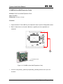
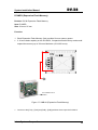
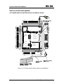
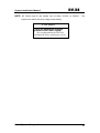
1
System Installation Manual DV-38 Ari s t e l Ne t w o rk s DV38 INSTALLATION GUIDE Version number 1.1 issued November 2004 Aristel Networks Pty Ltd Unit 3A, 100 Station Street Nunawading VIC 3161 Telephone: 03 9837 2300 Facsimile: 03 9872 4433 Arista Systems Corporation 1 System Installation Manual DV-38 INTRODUCTION .............................................................................................4 GENERAL DESCRIPTION ..............................................................................5 SYTEM CONFIGURATION..............................................................................7 SYSTEM CAPACITY AND SPECIFICATIONS ....................................................................7 KEY TELEPHONE SPECIFICATION......................................................................8 SYSTEM MODEL DESCRIPTION ..........................................................................9 FEATURE LIST.......................................................................................................10 ENVIROMENTAL REQUIREMENT ...............................................................12 EQUIPMENT REQUIREMENT ......................................................................13 POWER SUPPLY AND KSU INSTALLATION...............................................14 PCB AND CABINET LAYOUT ......................................................................15 D1MBUB (MOTHER BOARD UNIT) ..........................................................................16 D1PWUA (POWER BOARD UNIT).......................................................................18 D1TKUC (TRUNK UNIT, 4 TRUNK PORTS) .......................................................19 D1DTKA (ISDN BRI TRUNK UNIT) ........................................................................20 D1DLUB (DIGITAL KEY STATION UNIT, 8 KEY STATION PORTS) ..............................22 D1STUB (ANALOG KEY STATION UNIT, 8 KEY STATION PORTS) ..............................23 D1SLCB (SINGLE LINE STATION CARD, 2 SLT STATION PORTS) ..............................24 D1RSCA (RS232 CARD, 2400BPS SERIAL RS232 PORT) .........................................25 D1VSCA/B (VOICE SERVICE CARD, 2 VOICE CHANNEL).........................................28 D1MFCA (MULTI FUNCTION CARD, 2 SENSOR + 2 RELAYS + 2 DOOR PHONES) ......29 D1MDCA (METERING PULSE CARD) .......................................................................30 D1RPCA (REMOTE PROGRAMMING CARD, 2400BPS STANDARD MODEM)...............32 D1VMCA (VOICE MAIL CARD) ...............................................................................33 D1VMEA (VOICE MAIL EXPANSION CARD).............................................................34 D1VMFA (EXPANSION FLASH MEMORY) .................................................................35 INSTALLATION AND WIRING ......................................................................36 AC POWER AND DC BATTERY BACK-UP INSTALLATION............................36 D1MBUB JUMPER SETTING ...............................................................................38 POTS CO LINE WIRING FOR D1TKUC...............................................................39 D1CIDC AND D1MDCA INSTALLATION .............................................................40 DIGITAL KEYPHONE WIRING FOR D1DLUB .............................................................41 2 Arista Systems Corporation System Installation Manual DV-38 ANALOGUE KEYPHONE WIRING FOR D1STUB.........................................................42 50 PINS (25 PAIRS) MALE AMPHENOL CONNECTOR LAYOUT ....................................43 SINGLE LINE PHONE WIRING FOR D1SLCB .............................................................44 2-WIRES DOOR PHONE INSTALLATION ......................................................................45 SENSOR INSTALLATION .............................................................................................46 DOOR SWITCH INSTALLATION ...................................................................................47 EXTERNAL MUSIC SOURCE INSTALLATION ................................................................48 RS232(SERIAL PRINTER OR PC)INSTALLATION ..............................................49 SPECIFICATIONS ARE SUBJECT TO CHANGE WITHOUT NOTICE Arista Systems Corporation 3 System Installation Manual DV-38 INTRODUCTION This manual provides detailed procedures to install your new ARISTEL DV-38 Digital Key Telephone System. Please read this entire section before proceeding with the actual installation. The National Electrical Code (NEC) requires the local telephone company (Telecom) to provide the primary protection devices for the telephone lines terminating at the customer’s site. Make sure that a primary protection device has indeed been installed by the Telecom. If no such device is present, notify the Telecom before installing your Aristel system. 4 Arista Systems Corporation System Installation Manual DV-38 GENERAL DESCRIPTION Aristel DV-38 Fully Digital Key Phone System is an intelligent Telecom device and based on state of the art advanced technology. This system uses digital circuitry employing PCM, TDM, 2B+D, etc. The multi-function digital key phone has very flexible programming functions. The users can simply operate the DSS keys to activate the applications as they require. The new built-in Voice Mail not only provides standard voice mail functions but also has the Intelligent Recording function – to record message during conversation. The Windows version Customer Manager System (CMS) is fully integrated into the system to make customer management easier and more efficient. Aristel DV-38 Intelligent Digital Key Telephone System, has the listed capacities:trunk card (basic 4 lines per card, maximum 3 cards = 12 ports) and 8~26 extension ports. It can also be equipped with the following system peripherals: SMDR interface, Door Phone Interface, Multi-Function Sensor Interface, Multi-Function Relay, Remote Programming Interface, External Music Interface, External paging interface, Voice Mail and Auto Attendant Interface, DECT Interface, ADSL/ISDN…etc. Aristel DV-38 Digital Intelligent Key Telephone System uses modular PCB construction. External-Line, Internal-Line and peripherals of the main system are completely independent PCBs. All functions are able to be programmed to Macro keys, enabling complex functions to covert into single-keypad operation. This is an excellent option for the new digital age; Aristel DV-38 is the best partner to lead you into the diverse broadband world of telecommunications Arista Systems Corporation 5 DV-38 System Installation Manual Aristel DV-38 Digital Intelligent Key Phone System Multiple Processors. Time Division Multiplexing. Unique ARISTEL ASIC Chip “A-SERIES” 6 Arista Systems Corporation DV-38 System Installation Manual SYSTEM CONFIGURATION System Capacity and Specifications DV-38 Basic Capacity Expandable Capacity Max. Capacity POTS 4 8 12 ISDN (BRI) 0 0~6 6 Digital 8/0 16/0 24/0 Analog 0/8 0/16 0/24 0 2 2 Auto Attendant 0 4/0 4/0 Voice Mail 0 0/4 0/4 Recording Extension 0 26 26 Door Phone interface 0 2 2 Relay Switches 0 2 2 Sensor 0 2 2 Fax Monitor 1 2 3 RS232 For SMDR 0 1 1 Remote Programming 0 1 1 UPS interface 1 0 1 Speed Dial 1000 sets 0 1000 sets Caller ID card 0 12 12 Power Failure Transfer Phone 1 2 3 External Music 1 0 1 External Paging 0 1 1 DSS64 consoles N/A N/A 4 CO Line Key phone Single Line Phone Voice Service interface Arista Systems Corporation 7 DV-38 System Installation Manual KEY TELEPHONE SPECIFICATION DIGITAL KEY TELEPHONE Key Phone Model DKP30 DKP31 DKP32 DKP33 DKP50 DKP51 DKP52 DKP53 DSS Function Key 12 Keys 12 Keys 12 Keys 12 Keys 25 Keys 25 Keys 25 Keys 25 Keys 2 * 16 digits LCD Display … 9 … 9 … 9 … 9 Back-Light LCD Display … … … … … Option … Option Hands-Free Dialing 9 9 9 9 9 9 9 9 Direct intercom 9 9 9 9 9 9 9 9 Outgoing Call Hands-Free … … 9 9 … … 9 9 9 9 9 9 9 9 9 9 9 9 9 9 9 9 9 9 Digital Volume Control 8 Levels 8 Levels 8 Levels 8 Levels 8 Levels 8 Levels 8 Levels 8 Levels OHCA Function … … 9 9 … … 9 9 One Touch Paging 9 9 9 9 9 9 9 9 Last Number Redial 9 9 9 9 9 9 9 9 Name Speed Dial … 9 … 9 … 9 … 9 Calculator … … … … … 9 … 9 Individual Speed Dial 9 9 9 9 9 9 9 9 Difference Ringing Frequencies 9 9 9 9 9 9 9 9 Dual Color Tri Status LED 8 keys 8 keys 8 keys 8 keys 16 keys 16 keys 16 keys 16 keys One Digit Auto Answer 9 9 9 9 9 9 9 9 Incoming LED Indication 9 9 9 9 9 9 9 9 Internal/External Direct Dial Photo Interrupt Hook Switch Remarks: Postfix W= White Color, C= Dark Grey Color, B= Back-Light LCD Display 8 Arista Systems Corporation DV-38 System Installation Manual SYSTEM MODEL DESCRIPTION Model Description Main Service Unit - Consisting of Plastic Cabinet + D1MBUB + D1-408DK D1PWUA + D1TKUC + D1DLUB Remark Standard Shipment D1CBMA Main Service Unit - Consisting of (Plastic Cabinet + D1MBUB + Standard Shipment D1PWUA) D1MBUB Mother Board Unit Spare Part D1PWUA Power Unit Spare Part D1TKUC Trunk Unit - Consisting of 4 PSTN ports with Polarity Reverse, one Fax port Connector 、 one PFT port connector and Interface for D1MDCA and D1CIDA Connections. D1DTKA ISDN Trunk Card - Consisting of 2 BRI S/T interface D1DLUB Digital Key Station Unit – Consisting of 8 Digital Key Station ports Expansion Card D1STUB Key Station Unit – Consisting of 8 Analog Key Station ports Expansion Card D1SLCB Single Line Station Card – Consisting of 2 Single Line Station Ports Expansion Card D1RSCC RS232 Card – Providing 1 RS232 port and working for SMDR Optional Card D1VSCA Voice Service Card – Consisting of 2 Voice Channels (60 sec. per channel) for Auto Attendant applications Optional Card D1VSCB Voice Service Expansion Card - Additional 2 Voice Channels (60 sec. per channel) for Auto Attendant applications Optional Card D1MFCA Multi Function Card – (2 Doors + 2 Relays + 2 Sensors + 1 External Paging) Optional Card D1MDCA Meter Pulse Detection Card - 12KHz/16KHz Meter Pulse Detection Optional Card D1CIDC FSK/DTMF CLI Interface - One Channel of POTS Caller Number Identification Card Expansion Card D1RPCA Remote Programming Card - Providing 1 standard modem port 2400 bps) and working for Remote maintenance Optional Card D1VMCA Built-in Voice Mail Card - 2 ports of Voice Mail with 6.5 hours recording time Optional Card D1VMEA Voice Mail Expansion Card - one port of Voice Mail Optional Card D1VMFA Expansion Flash Memory - Software control with 4 hours store memory Optional Card WP5007 25-Pair Amphenol Cable – (for Station Wiring Connection) Arista Systems Corporation Expansion Card Optional Card Optional Required 9 DV-38 System Installation Manual FEATURE LIST System Features List z z z z z z z z z z z z z z z z z z z z z z z z z 3 Parties Conference 5 Different Trunk Access Codes Account Code Auto Attendant Auto Accessing Trunk Automatic Answer Auto Pick Up Automatic Call Distribution (ACD) Automatic Transfer Baby Listening Be/Internal/External/Group Paging Built-in Voice Mail Caller’s Number Identification (Caller ID) Call Limit Time Duration Call Park Call Split Data Monitor Console Grouping Date/Time Setting Day Time Schedule Day/Night Service Direct Intercom Dialing Direct Inward Dialing (DID) Direct Inward Station Access (DISA) Door Phone Connection Door Switch Control EMI Filter Environment Monitor External Call Forward (ECF) Fax Monitor Flexible Function Key Assignment Forced Account Code Headset Function Hot Line Hotel/Motel Function w/o PC Illegal Outgoing Protection z z z z z z z z z z z z z z z z z z z z z z z z z Intercom Busy Reminder Incoming Hunting Incoming Paging Intercom Hunting Internal/External Music Source Internal/External Paging ISDN Compatible Key Station Short Protection LCR (Least Cost Routing) Lightning Protection Manual Line Message Waiting Metering Pulse Detection Name Speed Dialing (Phone Book) One Touch Operation Polarity Reverse Power Failure Telephone Private Line Programming Help List Remote Programming Remote Relay Control Security/Fire Alarm System Single Digit Dialing SLT Hold Message/Function Capability Station Loud Bell SOS Station Message Details Report (SMDR) System Alarm Toll Restriction Tone/Pulse Dialing Trunk Grouping Trunk Loud Bell Trunk Queuing Unsupervised Conference Means the optional function. 10 Arista Systems Corporation DV-38 System Installation Manual Station Features List z z z 16×2 Dot-Matrix LCD Display 5 Different Numbers Auto Redial 9 Different Ringing Frequencies on Key Station z Adjustable LCD Angle (DKP50) Back Light LCD Display Calculator Function (Display Phone) z Call Forward/Call Follow Me z Call Forward To Individual Speed Dial z Call Pick Up z Call Transfer z Camp On z Conference z Day/Night Service Indication z Digital Volume Control (8 Levels) z Do Not Disturb z Dual-Color/Tri-Status BLF Indication z z z z z z z z z z z z z z z Ergonomics Receiver Handset Handsfree Dialing Handsfree Conversation Hold/Exclusive Hold Last Number Redial Macro Key Setting Message Text Monitor Off Hook Call Announcement (OHCA) Override Page/Be Paged Station Lock/Unlock Station Name Setting Station Operation Help List Station Lock/Unlock Station Name Setting Station Operation Help List means the optional function. Arista Systems Corporation 11 System Installation Manual DV-38 ENVIROMENTAL REQUIREMENT z The Key System Unit (KSU) should be installed at a clean, dry and secure location accessible only by authorized personnel. The location must have adequate ventilation and a temperature range between 0 ~ 45o C with a 10 ~ 90% non-condensing relative humidity. z The installation site should have sufficient room to mount the KSU along with the necessary connecting blocks and ancillary equipment on a wall. The installation site should not be in areas subject to static electricity (e.g. Dry copiers), or vibration (e.g. Heavy machinery). z A dedicated earthed power outlet for the KSU (either 240VAC/50Hz or 110VAC/60Hz) and a 10 Amp circuit are required. An integral earth is required in the AC power cord. If a music source or optional external paging equipment is installed, it must be connected to an AC circuit separate from the KSU’s dedicated AC line. ONLY THE KSU’S POWER SUPPLY SHOULD BE CONNECTED TO THE DEDICATED AC OUTLET. 12 Arista Systems Corporation System Installation Manual DV-38 EQUIPMENT REQUIREMENT Prior to installation, carefully inspect all packages for evidence of damage. Compare the equipment received against equipment ordered to ensure that ALL components have been received. The following materials are required (not provided) for installation: z Exterior grade plywood back board for the KSU. z 1 Male-Tail per extension board for Station wiring. z Appropriate mounting hardware. Arista Systems Corporation 13 DV-38 System Installation Manual POWER SUPPLY AND KSU INSTALLATION z Attach the plywood back board to the selected location with the appropriate fasteners. z A surge protector should be installed at the dedicated AC outlet. z Connect Male-Tail, and connect the plug to each station board for station wiring; also connect the wire to the RJ-11 for connector on each trunk card for the CO lines wiring. z Plug in the power cord of the power supply to an AC Power Outlet and then turn on the power of the system. 14 Arista Systems Corporation DV-38 System Installation Manual PCB AND CABINET LAYOUT SYSTEM INTER-CIRCUIT LAYOUT D1PWU D1SLC D1VSCA D1VMCA D1DLUB D1STUB D1MBUB D1RPCA D1RSC D1TKUC D1DTKA D1MFC Figure 1. System Inter-Circuit Layout 1. AC Power Inlet. 2. AC Power Switch. 3. Power Indicator(LED Type). 4. DC Power Switch. 5. For D1SLCB Earth Grounding. 6. 2-Wire Female Connector.(For External Battery Box Connection). 7. Earth Ground(For Lightning Protection Ground). 8. Wiring Area and the Cable Outlet. 9. RS232(Female DB9)for the connection to the D1RSCC. Arista Systems Corporation 15 DV-38 System Installation Manual D1MBUB (Mother Board Unit) Product: DV-38 Mother Board Unit Item: D1MBUB Size: 310 mm x 130 mm Function: 1. The motherboard control entire system functions and audio switching. 2. Motherboard supports External Music Source Input Terminal. 3. System programming Auto-Protection by Li Battery. 10 1 2 11 3 4 12 5 13 The installation site of D1MBUB 6 14 15 7 8 16 17 9 16 Arista Systems Corporation System Installation Manual 1. POWER: DV-38 6 pins Wafer Connector to connect with D1PWUA by 6 wires cable [HD-3903-10, VH Type] 2. VSC: 20Px2 Wafer Connector for D1VMCA or D1VSCA connections. 3. EPROM: 4. CPU: Intel 80188 Processor. 5. RPC: 20Px2 Wafer Connector Either D1RPCA or D1RSCB connections. 6. BAT: “3 VDC, 180mA/H” Li-Battery to back-up system programming data during Flash Memory EPROM “MX28F2000” which stored the system software. AC power failure. 7. RSC: 10Px2 Wafer Connector for D1RSCC connection. 8. SVR: Variable Resistor to adjust the volume of the Internal Melody Source that use for [BGM] and [MOH] applications. 9. MFC: 13Px2 Wafer Connector for D1MFCA connection. 10. SLC: 13Px2 Wafer Connector for D1SLCB connection. 11. STA1~3: 30Px2 Header Connector for both D1DULB and D1STUB connection. 12. ASIC: Aristel proprietary ASIC. 13. LCD: Additional LCD connector for engineering system maintenance. 14. JP1: 3 Pins Wafer Jumper to turn ON/OFF Li battery power. 15. TKU1~3: 25Px2 Header Connector for both D1TKUC and D1DTKA connection. 16. JP2: 3 Pins Wafer Jumper for Internal/External music selection. 17. EX-MUSIC: The input terminal for External Music Source connection. Arista Systems Corporation 17 DV-38 System Installation Manual D1PWUA (POWER BOARD UNIT) Product: DV-38 POWER UNIT Item: D1PWUA Size: 270 mm x 95 mm 1 5 2 6 Function: 3 7 1. To supply entire system power. 2. The input AC Voltage ranges are AC110V~240V 3. Support 24V Battery Charger for external Back-up Battery. The installation site of D1PWUA 4 Figure 3. D1PWUA (POWER UNIT) 1. LED501: 2. SW101: AC Power Switch. 3. CN101: AC Power Inlet. 4. CN802: 4 Pins Connector. (Reserved for further Applications) 5. SW401: External backup battery Power Switch. 6. CN105 : Earth Terminal for D1SLCB Grounding. 7. CN402: External Battery Connector; Left Side is (+), Right side is (-). 8. CN301 : 6 Pins Connector for D1MBUB connection. 18 Power Indicator. Arista Systems Corporation 8 DV-38 System Installation Manual D1TKUC (TRUNK UNIT, 4 TRUNK PORTS) Product: DV-38 TRUNK UNIT Item: D1TKUC Size: 162 mm x 122 mm Function: 1. Support Polarity Reverse detection for each CO lines. 2. A maximum of 3 D1TKUC boards can be installed onto the DV-38 main frame. 4. Support either D1CIDC or D1MDCA connections on each CO line. 1 2 The installation site of D1TKUC, D1DTKA 4 3 Figure 4. D1TKUC (TRUNK UNIT, 4 TRUNK PORTS) 1. CN1: 60-Wires rainbow Cable to connect to TKU1~3 positions where upon the D1MBUB. 2. CN3: The socket for both Power Failure standard Phone and FAX connections. 3. CN2: The RJ socket for POTS CO lines connections. 4. CH1~4B: Connectors for each CO lines to interface either D1CIDC or D1MDCA. Arista Systems Corporation 19 DV-38 System Installation Manual D1DTKA (ISDN BRI Trunk Unit) Product: DV-38 ISDN TRUNK UNIT Item: D1DTKA (ISDN BRI CARD) Size: 162 mm x 122 mm Function 1. Supports 2 lines of 2B+D interface which support 4 voice channels. 2. The system provides 3 slots of ISDN Trunk Unit connector. (Maximum expansion capability: 6 lines for 2B+D or 12 lines for Voice channel.) 1 2 7 4 6 3 The installation site of 5 D1DTKA Figure 5. D1DTKA (ISDN TRUNK UNIT, 2 BRI PORTS) 1. Test Connector for engineer testing. 2. Test Connector for engineer testing. 3. Flat cable connect to D1MBUB. 4. RJ-45 connector to connect to ISDN BRI Line. 5. JP1 jumper for first line-line termination enable/disable. DO NOT ALTER 6. JP2 jumper for second line-line termination enable/disable. DO NOT ALTER 7. JP3 jumper for DTKA card of TKU slot number. See table on next page. 20 Arista Systems Corporation DV-38 System Installation Manual JP1: Short: line termination enable (default). N/C: line termination disable. JP2: Short: line termination enable (default). N/C: line termination disable. JP3: please see below table for reference. Link # 0 IN REMOVED IN Link # 1 IN IN REMOVED Arista Systems Corporation Slot number of TKU 1 2 3 21 DV-38 System Installation Manual D1DLUB (Digital Key Station Unit, 8 Key Station ports) Product: DV-38 DIGITAL KEY STATION UNIT Item: D1DLUB Size: 162 mm x 155 mm Function: 1. Supports 8 ports of digital Key Phone interface. 2. Totally 3 pieces of D1DLUB could be installed onto the DV-38 main frame (24 Extensions Maximum). 4. D1DLUB fully compatible with DV-Series Key Telephones. Ex: DKP-30, DKP-31, DKP-32 DKP-33, DKP-50, DKP-51, DKP-52, DKP-53. 1 The installation site of D1DLUB, D1STUB 2 Figure 6. D1DLUB (Digital Key Station Unit, 8 Key Station ports) 1. STA: 60-wires Rainbow Cable to connect to SAT1~3 positions where upon the D1MBUB. 2. CN1: Am phenol Connector Key Station Wiring. 22 Arista Systems Corporation DV-38 System Installation Manual D1STUB (Analog Key Station Unit, 8 Key Station ports) Product: DV-38 ANALOG KEY STATION UNIT Item: D1STUB Size: 162 mm x 155 mm Function: 1. Supports 8 ports of digital Key Phone interface. 2. Totally 3 pieces of D1STUB could be installed onto the DV-38 main frame (24 Extensions maximum). 3. D1STUB fully compatible with AV-Series Key Telephones. Ex: KP-10 Series , KP-20 Series or KP30 Series. 1 The installation site of D1DLUB, D1STUB 2 Figure 7. D1STUB (Analog Key Station Unit, 8 Key Station ports) 1. CN1: 60-wires Rainbow Cable to connect to STA1~3 positions where upon the D1MBUB. 2. CN2: Am phenol Connector for analogue Key Station Wiring. Arista Systems Corporation 23 DV-38 System Installation Manual D1SLCB (Single Line Station Card, 2 SLT Station Ports) Product: DV-38 SINGLE LINE STATION CARD Item: D1SLCB Size: 195 mm x 69 mm Function: 1. D1SLCB provides 2 SLT Stations Ports. of occupying Extension ports socket. 2. It is installed on a special socket instead All of single line station can be connected to SLT ports. EX, SLT, Modem, Wireless Phone. 1 2 The installation site of D1SLCB Figure 8. D1SLCB (Single Line Station Card, 2 SLT Station Ports) 1. CN1_B: 6 Pins Wafer Connector for both Single Line Telephone Ports connections. 2. SLC: Wafer Connector to connect to [SLC] Position where upon the D1MBUB. 24 Arista Systems Corporation DV-38 System Installation Manual D1RSCC (RS232 Card, 2400bps Serial RS232 Port) Product: DV-38 RS232 CARD Item: D1RSCA Size: 51.5 mm x 69 mm Function: 2400bps Serial interface is used for SMDR and Aristel’s WinSM applications. 1 2 3 4 5 6 The installation site of D1RSCC Figure 9. D1RSCC (RS232 Card, 2400bps Serial RS232 Port) 1. CN: 10-Pins Male Wafer Connector. Connect to the position of Point 9 in Figure 1 by the special DB9 Cable [FD-10-9-400, Male Type] for the connection of either PC COM Port or Serial Printer. 2. RSC: 26-Pins Connector to connect to [RSC] position where upon the D1MBUB. 3. Jumper Setting. 3.1 JP4: 3-Pins Jumper Selection. Receive (SYS→ PC) JP4 Arista Systems Corporation 25 DV-38 System Installation Manual Transmit (SYS← Serial Printer) JP4 3.2 JP3: 3-Pins Jumper Selection. Receive Transmit 3.3 JP2: 3-Pins Jumper Selection. PC COM Port P (SYS← PC) P JP2 Transmit (SYS→ Serial Printer) JP2 3.4 JP1: 3-Pins Jumper Selection. Receive (SYS→ PC) JP1 JP1 26 Arista Systems Corporation DV-38 System Installation Manual CAUTION! A. If the system’s RS232 is connected to PC, please make ALL jumpers to be [PIN1 + PIN2] SHORTED. JP2 JP1 JP3 JP4 B. If the system’s RS232 is connected to Serial Printer, please make ALL jumpers to be [PIN2 + PIN3] SHORTED. JP1 JP2 JP3 JP4 C. Note:Some serial printers have already changes the TX. Rx. DTR. DSR mode. If those didn’t change, the system of mini jumper must change to pin1 & pin2. Arista Systems Corporation 27 DV-38 System Installation Manual D1VSCA/B (Voice Service Card, 2 Voice Channel) Product: DV-38 D1VSCA/D1VSCB Model: D1VSCA/D1VSCB Size: 138 mm x 69 mm Function: 1. D1VSCA is consisting of 2 voice service channels which provide 60 seconds nonvolatile memory space in each. 2. Each channel could be pre-recorded the voice for Auto-Attendant and Emergence Call applications. 1 2 3 The installation site of D1VSCA/B, D1VSMA 4 Figure 10. D1VSCA/B (VOICE SERVICE CARD, 2 VOICE CHANNEL) 1. VSC: 26-Pin Connector to connect to [VSC] position where upon D1MBUB. 2. Expansion Connector for D1VSCB connection. 3. Variable Resistors. To adjust the Playing Volume of each voice channel. 4. The expansion Connector to connect both D1VSCA and D1VSCB for channel expansion. 28 Arista Systems Corporation DV-38 System Installation Manual D1MFCA (Multi Function Card, 2 Sensor + 2 Relays + 2 Door Phones) Product: DV-38 MULTI FUNCTION CARD Item: D1MFCA Size: 83.5 mm x 69 mm Function: 1. The Multi Function Card provides 2 ports of Door Phone interface, 2 ports multi function Relay Switch, 2 Ports of Multifunction Sensor interface, 2 ports of External Paging interface. 2. Multi function card is an important interface of communicating others related products in our DV-38 .ex, Sensor Control, Relay Control, External Paging, Fire Alarm, and Emergency Alarm. .etc. 1 The installation site of D1MFCA 2 3 4 5 Figure 11. D1MFCA (Multi Function Card, 2 Sensor + 2 Relays + 2 Door Phones) 1. SEN2: Terminal-Block Connector for the 2nd Sensor Connection. 2. SEN2: Terminal-Block Connector for the 1st Sensor Connection. 3. External Page: Terminal-Block Connector for External Page Connection. 4. DOOR2: Terminal –Block Connector for the 2nd Door Phone Connection. 5. DOOR1: Terminal –Block Connector for the 1st Door Phone Connection. 6. SW2: Terminal-Block Connector for the 2nd Relay Connection. 7. SW1: Terminal-Block Connector. For the 1st Relay Connection 8. AUX: The Connector to connect [MFC] position where upon the D1MBUB. Arista Systems Corporation 29 DV-38 System Installation Manual D1MDCA (Metering Pulse Card) Product: DV-38 Metering Pulse CARD Item: D1MDCA Size: 91 mm x 21 mm Function: Provide signal channel of the POTS CO line 12/16KHz Metering Pulse detection. The installation site of D1MDCA 2 1 Figure 12. D1MDCA (Metering Pulse Card) 1. CN2: To connect to the position [CH1~4B] where upon the D1TKUC. 2. CN1: To connect to the position [CH1~4A] where upon the D1TKUC. 30 Arista Systems Corporation DV-38 System Installation Manual D1CIDC (CALLER ID Card) Product: DV-38 CALLER ID CARD Item: D1CIDC Size: 91 mm x 21 mm Function: Provide signal channel of the POTS CO line DTMF/FSK Calling Line Identification detection. The installation site of D1CIDC 1 2 Figure 13. D1CIDC (CALLER ID Card) 1. CN2: To connect to the [CH1~4B] position where upon the D1TKUC. 2. CN1: To connect to the [CH1~4A] position where upon the D1TKUC. Arista Systems Corporation 31 DV-38 System Installation Manual D1RPCA (Remote Programming Card, 2400bps Standard Modem) Product: DV-38 REMOTE PROGRAMING CARD Item: D1RPCA Size: 70.5 mm x 69 mm Function: 1. Standard 2400bps Modem. 2. Cooperate with Aristel’s Win-SM for system remote programming and Maintenance. 1 The installation site of D1RPCA Figure 14. D1RPCA (Remote Programming Card) 1. 32 RPC: 26-Pin Connector to connect to [RPC] position where upon the D1MBUB. Arista Systems Corporation DV-38 System Installation Manual D1VMCA (Voice Mail Card) Product: DV-38 VOICE MAIL CARD Item: D1VMCA Dimension: 225 mm x 124 mm Function: 1. Support 2 basic Voice mail on board and could be expanded up to 4 ports by D1VMEA. 2. On board Flash memory chip to stores the voice message. 1 2 3 The installation site of D1VSMA Figure 15. D1VMCA (Voice Mail Card) 1. Expansion Flash Memory for D1VMCA 2. Expansion Voice Mail Port for D1VMCA 3. Flat cable connector to connect to the [VSC] position where upon the D1MBUB. Arista Systems Corporation 33 DV-38 System Installation Manual D1VMEA (Voice Mail Expansion Card) Product: DV-38 Voice Mail Expansion Card Item: D1VMEA Dimension: 41 mm x 41 mm Function: 1. Signal channel of Voice Mail for port expansion where upon the designated socket. 2. Basic 2 channels on one board, Maximum capability can be expanded to 4 channels. 1 The installation site of VMB-01 Figure 16. D1VMEA (Voice Mail Expansion Card) 1. Connect to the [DSP3A] , [DSP4A] and [DSP3B] , [DSP4B] positions where upon the D1VMCA. 34 Arista Systems Corporation DV-38 System Installation Manual D1VMFA (Expansion Flash Memory) Product: DV-38 Expansion Flash Memory Item: D1VMFA Size: 30 mm x 25 mm Function: 1. Each Expansion Flash Memory Card provides 8 hours memory space. 2. 2. 6 hours basic capacity on the D1VMCA, 3 expansion flash memory cards could expand the memory up to 30 hours Maximum (6+24=30 hours). 1 The installation site of VMB-01 Figure 17. VMB-04 (Expansion Flash Memory) 1. Connect to the [F2A] ~ [F5A] and [F3B] ~ [F5B] positions where upon the D1VMCA. Arista Systems Corporation 35 DV-38 System Installation Manual INSTALLATION AND WIRING AC POWER AND DC BATTERY BACK-UP INSTALLATION D1SLCB D1VSCA D1VMCA D1DLUB D1STUB D1RPCA D1RSC D1MFCA D1TKUC D1DTKA Figure 18. AC Power and DC Battery Back-Up Installation 36 Arista Systems Corporation DV-38 System Installation Manual NOTE. AC Power input to the system can be either 115VAC or 230VAC. The system can detect the input voltage automatically. CAUTION There are Hazardous voltages present in the Power Supply. We recommend that the Power be switched off before opening any covers. Arista Systems Corporation 37 DV-38 System Installation Manual D1MBUB JUMPER SETTING Please refer Figure 2 the D1MBUB plot for detail positions. 1. Li Battery installation and jumper setting. 1.1 [JP1] – Li Battery power ON/OFF. 1.2 [BAT] – Battery Holder. CAUTION Danger of explosion if battery is incorrectly replaced. Replace only with the same or equivalent type recommended by the manufacturer. Dispose of used batteries according to the manufacturer’s instructions. 2. Music source selection and volume control for both MOH and BGM. 2.1 [JP2] - Music Source Selection. External Music Source Internal Music Source 2.2 [VR1] – Volume Control. 38 Arista Systems Corporation DV-38 System Installation Manual POTS CO LINE WIRING FOR D1TKUC 6 5 4 3 2 1 6 5 4 3 2 1 PFR1 PFT1 FAX-R FAX-T COR4 PFR1+PFT1 ===> PF Tel. 1 FAX-R+ FAX-T ===> FAX Machine COR4+COT4 ===> CO Line 4 COT4 1. There are 4 CO Line Ports that can be wired on D1TKUC, each CO Line Port containing 2-wires. 2. The above diagram depicts the connection of a FAX machine working with FAX MONITOR function. 3. FAX monitor function installation is only available on D1TKUB. Arista Systems Corporation 39 DV-38 System Installation Manual D1CIDC and D1MDCA INSTALLATION D1CIDC / D1MDCA D1TKUC CH4B CH4A CH3B CH3A CH2B CH2A CH1B CH1A Figure 20. Metering Pulse Detection Card Installation 1. There is a maximum of 4 D1CIDC cards that can be installed in each D1TKUB, one card for one CO Line. 2. The connection for the 1st, 2nd, 3rd and 4th CO Lines are from (CH1A)+(CH1B)to(CH4A) +(CH4B). 40 Arista Systems Corporation System Installation Manual DV-38 Digital Keyphone Wiring for D1DLUB D1DLUB Phone Box 4 Wires Figure 21. Digital Key Station Wiring on D1DLUB 1. (ST1)~(ST8) are all for the Digit Key Telephone connections. 2. BT/BR is the Data/Audio/Power pair(no polarity). Arista Systems Corporation 41 DV-38 System Installation Manual Analogue Keyphone Wiring for D1STUB D1STUB CN1 Phone Box 4 Wire Figure 22. Analogy Key Station Wiring on D1STUB 1. (ST10~(ST8) are all for the Analogy Key Telephone connections. 2. AT/AR is the audio pair;AT = Transmission(Green Color), AR = Receiving(Red Color). 3. BT/BR is the Data/Power pair;BT=(-) Pole and Data Receiving (Black Color), BR = (+) Pole and Data Transmission (Yellow Color). 42 Arista Systems Corporation DV-38 System Installation Manual 50 Pins (25 Pairs) Male Amphenol Connector Layout Pair Pair 1 Pair 2 Pair 3 Pair 4 Pair 5 Pair 6 Pair 7 Pair 8 Pair 9 Pair 10 Pair 11 Pair 12 Pair 13 Pair 14 Pair 15 Pair 16 Pair 17 Pair 18 Pair 19 Pair 20 Pair 21 Pair 22 Pair 23 Pair 24 Pair 25 D1DLUB NC Pair 2 for Station 1 NC Pair 2 for Station 2 NC Pair 2 for Station 3 NC Pair 2 for Station 4 NC Pair 2 for Station 5 NC Pair 2 for Station 6 NC Pair 2 for Station 7 NC Pair 2 for Station 8 NC NC NC NC NC NC NC NC NC D1STUB Pair 1 for Station 1 Pair 2 for Station 1 Pair 1 for Station 2 Pair 2 for Station 2 Pair 1 for Station 3 Pair 2 for Station 3 Pair 1 for Station 4 Pair 2 for Station 4 Pair 1 for Station 5 Pair 2 for Station 5 Pair 1 for Station 6 Pair 2 for Station 6 Pair 1 for Station 7 Pair 2 for Station 7 Pair 1 for Station 8 Pair 2 for Station 8 NC NC NC NC NC NC NC NC NC The Above pairs refer to the standard color coding as they appear when terminated on the frames. Arista Systems Corporation 43 DV-38 System Installation Manual Single Line Phone Wiring For D1SLCB D1-SLCA Phone Box Wire Single Line Telephone Figure 23. SLT Station Wiring on D1SLCB 1. Connect D1SLCB on D1MBUB. 2. Only for 2 SLT ports (SLT1) and (SLT2) provided on D1SLCB can connect with Single Line Telephone. 3. 44 The wiring of (SLT2) to connect with Single Line Telephone is analogous to that of (SLT1). Arista Systems Corporation DV-38 System Installation Manual 2-Wires Door Phone Installation EXT PAGE AUX D1MFCA EXT PAGE Figure 24. Door Phone Wiring on D1MFCA 1. D1MFCA is an option, which must be installed to provide 2 Door Phone Connection. 2. This option allows the user to connect any kind of external 2-Wires Door Phone device. 3. The program setting refer to Zone 602. Arista Systems Corporation 45 DV-38 System Installation Manual Sensor Installation EXT PAGE AUX D1 MFCA EXT PAGE Figure 25. External Sensor Wiring on D1MFCA 1. D1MFCA is an option, which must be installed to provide 2 Sensor Connections. 2. This option allows the user to connect any kind of external SENSOR device, such as Door Sensor, Smoke Detector, or Heat Sensor, among others. 46 Arista Systems Corporation DV-38 System Installation Manual Door Switch Installation Connect to Door Switch Power EXT PAGE AUX D1 MFCA EXT PAGE Figure 26. Door Switch Wiring on D1MFCA 1. D1MFCA is an option, which must be installed to provide 2 Relay Connections. 2. This option allows the user to connect any kind of external Relay Control device, such as Door Switch, Loud Bell among others. Arista Systems Corporation 47 DV-38 System Installation Manual External Music Source Installation D1MBUB External Music Source Figure 27. External Music Source Wiring on D1MBUB 1. Connect 2-conductor wiring cord from External Music Source to (EXMUSIC) on D1MBUB. 48 Arista Systems Corporation DV-38 System Installation Manual RS232(Serial Printer or PC)Installation View from the D1MBUB Male DB9 which is RS232 Output Port of the system front of DB9 D1TKUB Wiring table Inside Wiring table Female DB9(Pin positions are viewed from the Rear inside DB9) Female DB9(Pin positions are viewed from the Rear inside DB9) DB-9 Male Connector Standard DB-9 Cable Inside Wiring table DB-9 Male Connector Connect to PC COM Port Serial Printer (or PC) including RS232 interface D1-MBUA RS232 D1-TKUB RS232 Output Connector DB-9 Male Connector “DB9 to RJ11” Convertor (GREY Color Box, Female) 6P6C Line Cord “DB9 to RJ11” Convertor (RED Color Box, Female) Serial Printer (or PC) including RS232 interface Figure 28. RS232 Wiring on D1MBUB (wired by customer) 2. Install D1RSCC (RSC) position on D1MBUB as the FIRST RS232 interface, or install D1RSCC to (RPC) position on D1MBUB as the SECOND RS232 interface. 3. Set up the jumper Selection onD1RSCC according to which one of PC or Serial Printer is connected to the system. Please refer to Figure 9. Point 2,3,4,5, on Page 29. Arista Systems Corporation 49