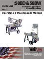
1
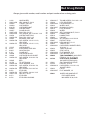
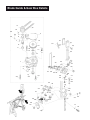
MODEL
58BD&58BW
Parts List
Portable/Convertible
Manual Bandsaw
and
Built better to work stronger and last longer
Operating & Maintenance Manual
REV 131109
2829 N. Burdick
rdick St. Kalamazoo, MI 49004
Phone: 269-345-1132
69-345-1132 Fax: 269-345-0095
www.wellsaw.com
Index
Full Year
Limited Warranty
Specifications ........................................................... 2
Warranty Info ............................................................ 2
Safety Instructions .................................................... 3
Operation & Maintenance ......................................... 5
Recommended Service Kit ....................................... 7
This WELLSAW is warranted against defects
in material or workmanship installed or performed at
the factory. Within one year fro, date of purchase, we
will free of charge and at our option, either repair or
replace any part of this WELLSAW which our examination discloses to be defective because of workmanship
or a defect in the material. This warranty does not apply if this WELLSAW has been used in a manner not
consistent with its’ design or which has been subject
to accident, alteration, abuse or misuse or which fails
due to lack of care or is the result of inadequate power
supply and specifically does not apply to normal wear
parts. THERE ARE NO WARRANTIES WHICH EXTEND BEYOND THE DESCRIPTION OF THE FACE
HEREOF.
WELLSAW shall not be liable for consequential
or incidental damages suffered or incurred with respect
to defective materials or workmanship.
We do not authorize any person or representative to
make any other warranty or to assume for us any liability in connection with the sale of our products other
than those contained herein. Any agreements outside
of or contradictory to the foregoing shall be void and of
no effect.
All transportation costs on products or parts
submitted to WELLSAW under this warranty must be
paid by the user. No products or parts are to be returned without first obtaining permission
Parts Drawings & Parts Lists
Bed & Leg ............................................................. 8-9
Wheel & Frame ................................................. 10-11
Blade Guide & Gear Box ................................... 12-13
Coolant, Switch & DashPot .............................. 14-15
Service Parts Changes (Before Serial # 22020)..... 16
Switch Box Assembly ............................................. 16
Trouble Shooting .................................................. 17
Electrical Schematic ............................................... 18
Wellsaw® Select-O-Chart........................................ 20-21
Specifications
Horizontal Capacity
Rectangular .......................................... 9.5” H x 11”W
Round .................................................... 9.5”Diameter
Flat......................................................................... 12”
45 Degree Angle .............................5-1/2”H x 5-1/2”W
Vertical Capacity
Work Table ...................................................... 8” x “10
Throat Height .....................................................9-1/2”
Throat Depth......................................................6-1/4”
Speeds, FPM .......................................... 76, 141, 268
Blade Size ............................ 1/2” x .025” x 7’-9” (93”)
Motor ............................................................... 1/2 HP
Bed Width ..........................................................8-1/2”
Floor to top of bed ................................................. 26”
Floor space ................................................... 26” x 54”
Height (Frame Vertical)....................................55-3/4”
Height (Frame Horizontal) ...............................42-3/4”
Approximate Shipping Weight, 58BD ............. 350 lbs
Aproximate Shipping Weight, 58BW ..............365 lbs.
For Your Convenience
When contacting your WELLSAW supplier or the
Company for parts or service, it is helpful to have
both your saw Serial Number and Purchase Date
available. Jot them down her for handy reference.
Serial Number:
Purchase Date:
Additional blades available:
6, 10, 14, 18 & 24 teeth per inch
2
SAFETY INSTRUCTIONS
Know your machine,
its safe and proper use!
DISCONNECT POWER before adjusting or servicing
the saw or changing a blade.
FOR ALL TOOLS
STAY CLEAR of all moving parts. Keep hands and
fingers away form the saw blade.
KEEP GUARD IN PLACE and in working order.
WHEN MOVING SAW, with hinged frame (saw head),
secure the head in its down position.
REMOVE ADJUSTING KEYS AND WRENCHES.
Form a habit. Check to see that all keys and wrenches
are removed from the tool before turning the tool on.
WHEN CUTTING MAGNESIUM, take special precautions. Use a sharp saw blade, make only dry cuts, prevent chip accumulation, and keep fire-fighting equipment nearby.
KEEP WORK AREA CLEAN. Cluttered areas and
benched invite accidents.
THIS SAW SHOULD BE GROUNDED WHILE IN USE
TO PROTECT THE OPERATOR FROM ELECTRICAL SHOCK.
AVOID DANGEROUS ENVIRONMENT. Do not use
power tools in damp or wet locations. Keep your work
area well lighted.
CORD CONNECTED TOOLS. If the saw is equipped
with an approved 3-conductor cord and a 3-prong
grounding type plug, it should only be connected to
a properly equipped and grounded receptacle. The
green conductor in the cord is the grounding wire.
Never connect the green wire to a live terminal.
KEEP CHILDREN AWAY. All visitors should be kept a
safe distance from work area.
MAKE WORKSHOP KID-PROOF with padlocks, master switches, or by removing starter keys form tools.
DON’T FORCE TOOL. It will do the job better and
safer at the rate for which it is designed
Use only a 3-wire extension cord having a 3-pronged
receptacle, a 3-pronged plug and ample amperage rating. Replace or repair a damaged or worn cord immediately.
USE RIGHT TOOL. Don’t use a tool a or attachment
to do a job for which it was not designed.
WEAR PROPER APPAREL. No loose clothing or jewelry to get caught in moving parts. Rubber-soled footwear is recommended for best footing.
PERMANENTLY CONNECTED TOOLS. The saw
should be connected to a grounded, metal-enclosed
wiring system or an equipment-grounding conductor
should be run with the circuit conductors and connected to the saw’s grounding terminal or lead.
USE SAFETY GLASSES. Also use face or dust mask
if operation is dusty.
To reset the manual starter after a power interruption,
return the switch to OFF and press the RESET button
before restarting.
SECURE WORK. Use clamps or a vise to hold work.
Provide adequate support to prevent injury from falling
work pieces.
3
MAINTAIN TOOLS WITH CARE. Keep tools sharp
and clean for best and safest performance. Follow instructions for lubricating and changing accessories.
The work area should be neat, well lighted, properly
ventilated and free of pedestrian or vehicle traffic. Ample room is needed for stock handling and storage,
the floors must be free of slipping or tripping hazards
as many machines have exposed tooling that can be
fallen on.
DISCONNECT TOOLS before servicing or when
changing accessories such as blades, bits, cutters, etc.
These items, though they are not specific machine
guard needs, are equally important.
AVOID ACCIDENTAL STARTING. Make sure the
switch is in OFF position before connecting power
tools.
It is also interesting to note that operators observed
and questioned by the survey representatives and employed on some woodworking and metalworking equipment are often new hires with little or no experience
with machine operation. This is substantiated by the
finding that proper training programs are almost absent
from industry (Field Supplement, page 8) and by the
fact that the highest percentage of accidents occurs
at a young age (see Field Survey Supplement, page
8). The best example of this is with operators of saws
where the operation seems self-explanatory through
observation. Perhaps the operation is basically simple; nevertheless, operators should be carefully trained
and enthusiastically motivated to perform safely.
DON’T OVER REACH. Keep proper footing and balance at all times.
USE ONLY RECOMMENDED ACCESSORIES. Consult the owner’s manual for recommended accessories.
The use of improper accessories may be hazardous.
NEVER STAND ON A TOOL. Serious injury can occur if the tool is tipped or the cutting tool is accidentally
contacted.
CHECK DAMAGED PARTS. Before further use of the
tool, a guard, or other part that is damaged, should be
carefully checked to ensure that it will operate properly and performed its intended function. Check for
alignment of moving parts, breakage, mounting and
any other condition that may affect the tool’s proper
operation. Any guard or part that is damaged should
be properly repaired or replaced.
A final observation found through field surveys has to
do with the size of the company versus the number
of unguarded machines (see Field Survey Supplement, page 2). The smaller the company in number
of employees, the larger the percentage of unguarded
machines observed. This illustrates a further need for
machine guards.
This excerpt from a survey report does not necessarily reflect the views and policies of OSHA however it is
presented for your consideration in maintaining workplace safety.
The age of the operator, the size of the company, and
the lack of training programs, along with the investigation of specific machines to identify inherent hazards,
establishes a definite need for machine guarding. The
fact that a hazard exists and a worker performs in proximity to that hazard will undoubtedly result in an injury.
Because of this, the use of machine guards to divorce
the operator from the hazard to the highest possible
degree is not only desirable but needed. It is the moral
responsibility of the employer and expected benefit to
the employee to be able to manufacture goods without
occupational injuries.
From
“Machine Guarding Assessment of Need”
HEW publication No. (OSHA) 75-173
SUMMARY:
The previous information discussed specific machines
and their inherent characteristics and hazards. All machines, however, require proper power installation and
maintenance. High-speed, rotating cutting tools must
be properly sharpened and well balanced to eliminate
vibration. Saw blades must be properly sharpened
and set to eliminate binding and ensure clean cuts.
Any cutting tool that is cracked or chipped must be discarded.
4
Operation & Maintenance
READ CAREFULLY
The MODEL 58B METAL CUTTING BAND SAW is designed for efficient performance. With proper care, it
will give you many years of dependable service. READ
THIS MANUAL CAREFULLY BEFORE OPERATING
YOUR NEW SAW.
After final assembly, each saw is inspected and
tested. No adjustment should be needed.
This manual has been prepared to assist you in
the operation and maintenance of your new saw. If
you desire additional information or assistance, please
contact your dealer’s service representative.
9. Briefly start and stop motor a few times to make
sure blade is riding correctly on band wheels, then
tighten blade to proper operating tension.
10. Replace blade guard.
11. Lower frame for horizontal cutting.
12. Check safety bar. Be sure it is in proper position to
prevent frame from being raised beyond maximum
position when used as a horizontal cutt-off saw.
QUICK ACTION VISE
The sliding vise jaw is equipped with a ratchet dog
arm for quick action and a hand wheel for tightening
work in the vise. Excessive pressure is not required to
hold material securely in the vise.
INSTALLATION
Uncrate and check all parts. Report any damage
to your carrier and file a Proof of Loss Claim with the
carrier.
Be sure motor specifications correspond with your
power source.
Place the saw so that each leg is carrying its share
of the load. The 58B Saw can be operated horizontally
and vertically. For vertical operation. place frame in
upright position, attach the vertical work table and, operate switch manually.
FIXED JAW VISE
Two pins in the fixed vise jaw assist in the quick
relocation of the fixed vise jaw for 90° cutting. For final
and accurate adjustment, the blade should be squared
with the vise jaw by placing machinist’s square head
lightly against the side of the blade and the squares
blade against the machined face of the vise jaw.
NOTE: These pins must be removed before fixed
vise jaw can be turned. For angle cutting, use the
clamp bolts to hold fixed vise jaw.
Loosen sliding vise jaw and push against fixed jaw
vise jaw, then cap screw tightened, leaving vise jaws
parallel.
OPERATION
Do not apply too much feed rate. Start cut carefully
and the new blade will last much longer. Make sure all
four legs are in solid contact with the floor. Keep blade
guide as close to the work as possible.
MAXIMUM VISE CAPACITY & 45° ANGLE ADJUSTMENT
PLACING BLADE ON SAW
1a. DRY CUTTING MACHINE. Release from safety
latch bar and swing frame into vertical position.
1b. MACHINE WITH WET CUTTING SYSTEM. Remove chip pan, then follow instructions in 1a.
2. Open idler wheel hinged guard.
3. Remove blade guard.
4. Turn blade tension wing screw to lower the idler
wheel and slide block assembly.
5. Uncoil a 1/2” x 93” blade.
6. When facing cut-off side of machine, blade must
travel toward the motor end.
7. Be sure blade teeth point in this direction. If not,
twist blade band inside-out.
8. Install blade as follows:
a. Place blade between guide bearings and brushes.
b. Insert blade into slot between frame and guard.
c. Slide blade onto the drive and idler wheels.
d. Turn tension wing screw until blade is taut.
1. Remove blade brush assembly from blade guide
arm.
2. Remove the two 5/16” cap screws holding guide
arm to the frame.
3. Move guide arm back to the next two holes. Replace cap screws and tighten in place.
4. Remove vise jaw pins in fixed vise.
5. Remove 1/2” cap screw from quadrant.
6. Loosen cap screw in center of vise jaw and slide
vise toward motor end of machine about 2-1/4”.
7. Replace 1/2” cap screw in tapped holes and tighten
lightly.
8. With saw frame in cut-off position, place head of
machinist’s square lightly against slot in bed with
the blade of square against machined face of vise
jaw. Tap lightly with lead hammer until vise jaw is
parallel to blade of square. Tighten cap screws.
Use a protractor for angle adjustment.
5
DASH POT
MAINTENANCE
Wellsaws are equipped with a dash pot (frame
check) to stabilize the downward travel of the saw
frame to protect the saw blade from damage. The
action is hydraulic. The flow of fluid being bypassed
through an orifice controls the downward stroke of the
saw frame.
Fill the dash pot to within 1” of top of the bottom of
cylinder with Cities Service “Amplex 05” Hydraulic Oil
or equivalent.
BEFORE MAKING ANY ADJUSTMENTS, ALWAYS
TRY A NEW BLADE TO MAKE SURE THE CAUSE
OF THE PROBLEM IS NOT A WORN BLADE.
Blade guides are provided to hold the blade in both
horizontal and vertical alignment.
Accuracy of cut depends on proper adjustment of
the blade bearings. Check their condition for wear or a
tendency to stick. When the blade is moved sideways
or with a twisting action, the movement should stop at
the bearings and not be transferred beyond this point.
FRAME WEIGHT ADJUSTMENT
The position of the collar in relation to the spring on
the dash pot acts as the frame weight adjustment.
The proper frame weight is approximately 10 lbs.
and is obtained by positioning the collar 3-3/4” down
from the top edge of the upper cylinder to the top edge
of the collar. For less frame weight, loosen collar and
move downward toward tension spring. Reverse procedure for more frame weight.
Too much frame weight will cause the blade to cut
crookedly.
An eccentric axle is provided on each blade guide.
By rotating this axle, the bearing is drawn away from
the blade.
WHEEL PITCH ADJUSTMENT
If the blade runs too low on wheels, it may be because of too much blade tension. Loosen the blade by
turning the “T” handle (10) counterclockwise (CCW).
The blade must be reasonably tight.
If this adjustment does not correct the problem, adjust the wheel pitch. Usually, adjusting the idler wheel
will correct the problem. However, if it doesn’t, both
idler and drive wheels will have to be adjusted as follows:
SWITCH AND MOTOR
This saw is equipped with a start-stop switch that
automatically shuts off the motor at the completion of a
cut when the wheel guard contacts the switch control
lever to the desired position for proper shut-off.
It is necessary to raise the saw frame clear of the
switch control lever before the saw can be started.
Thermal overload protection is provided in the motor. Should the motor stop for other than normal reasons, it may be due to overload. After the problem has
been corrected, the motor may be reset by following
the instructions on the motor name plate.
1. Loosen blade tension until the blade is slack by
turning the “T” handle CCW.
2. Raise the frame into the vertical position. See Diagram.
3. Loosen 2 cap screws 7A and 7B 1/2 turn.. Then
tighten 2 cap screws 7C and 7D 1/2 turn.
4. Tighten blade by turning “T” handle CW. If the
blade then runs in proper position on both wheels,
no further adjustment is necessary.
SPEED SELECTION
If the blade runs back to the flange of the idler wheel
and not on the drive wheel, make the following adjustment:
Saws are equipped with step pulleys that provide
three speeds: 76, 141 and 268 blade feet-per-minute.
Change blade speed by loosening wing screw close to
the motor pivot. Place belt in desired position, tighten
wing screw until belt is snug and lock wing screw with
wing nut.
FAST speed to cut thin-wall metal, tubing, thin
brass or any metal that will not burn teeth.
MEDIUM speed on general cutting such as cold
rolled machine steels or any metals which require a
slow speed on a lathe.
Use beeswax when cutting brass. Brass should
always be cut with a new blade. If teeth wear unusually fast, use slower speed. Always keep the blade in
proper tension.
1. Loosen the 2 cap screws, 22E and 22F, at the motor end of the wheel plate.
2. Tighten the 2 Allen screws, 22G and 22H, about
1/2 turn.
3. Tighten all four cap screws.
4. Start the motor to see if the blade runs back to the
flange of the wheel.
CAUTION:
Too much pitch will wear the wheel
flanges and roll over the back of the blade! This
problem can usually be determined by the noise of
the blade rubbing against the flange. To check further, place a piece of paper between the blade and the
wheel. Start the saw. The blade should not shear the
paper but just fold it over. If it shears the paper, back
off the adjustment a little at a time until proper adjustment is reached.
6
BLADE BRUSHES
Blade brushes should be cleaned frequently with
kerosene or a good solvent. To take advantage of both
rows of bristles, invert blade brushes and install them
on the opposite side of the blade.
For best results, replace worn, filled or sticky brushes. When bolting brushes to the mounting angles, be
sure wire bristles are turned in the same direction that
the blade travels.
BLADE GUIDE ADJUSTMENT
1. Check the blade fit between guide bearings by
grasping the blade between the guide and the band
wheel.
2. Twist blade back and forth.
3. If too much clearance is found, rotate the eccentric
axle (34), page 12, until the bearing (32) is snug
against blade and all clearance has been removed.
4. Check guide bearing (32) with thumb by applying
force against bearing. It should be possible to rotate
the bearing while it is snug against the blade and all
clearance has been removed.
5. When looseness has been corrected, make another
cut. If the cut is not straight, further adjustment must
be made.
6. Place a square on the cut. Determine if the blade is
cutting toward or away from the bed or if it is out of
square with the vise.
7. If the vise is out of square, correct this by squaring
the vise with the slot in the saw bed.
8 If the cut is out of square on the vertical dimension,
correct this by moving the guides either away from
or towards the saw bed. This is accomplished as
follows:
a. Loosen the 2 cap screws (31), which hold the
guide (28) to the guide brackets (23 & 37). Hold
the guide from twisting and tap it in the desired
direction until the blade is square with the saw
bed. To do this:
1. Place a spacer between the frame wheel
guard and the switch box raising the blade
teeth just over the saw bed.
2. Place a machinist’s square on the saw bed
and move it to touch the body of the saw
blade - making sure it does not touch the
blade teeth.
3. Use a feeler gauge, .002” or less, to see that
the lade is square from top to bottom. If
further adjustment is needed, loosen cap
screws on one blade guide and rotate guide
so the feeler gauge will not enter at top or
bottom. Do not move guide sideways. This
may move the blade out of square with the
vise. Tighten cap screws.
LUBRICATION
Correct and adequate lubrication is very important
to achieve maximum service. It is imperative that all
dust and dirt be removed before lubricating.
7
Marfak Grade “O” Grease, or equivalent, is used
in the gear case. Other parts of the saw may be lubricated as follows:
1. Vise adjusting screw. Use a heavy oil or light
grease.
2. Keep internal ring gear and pinion well lubricated
with a good quality, medium grade, fibrous grease.
3. Wheel ball bearings are sealed and permanently
lubricated.
4. For proper motor lubrication, follow the motor manufacturer’s instructions.
LUBRICATION SUMMARY
GEAR CASE:
Service interval; inspect after 3 years and
annually thereafter.
Lubricant: Mobilgrease XHP220 or
equivalent.
VISE SCREW, RING GEAR, PINION: Inspect monthly
Lubricant: Use Anti-seize on vise screw
Use Extreme Pressure Open Gear Lube on ring
and pinion gears sparingly.
HELPFUL SUGGESTIONS
1. To select proper blade, consider the type of material to be cut as well as to its size and shape. The
SELECT-O-CHART is a handy reference guide.
2. Use the correct blade speed and correct pressure
for each type of material cut.
3. Always maintain proper blade tension.
4. Lower saw frame carefully so that the blade will
start cutting before full frame feed pressure is applied to the blade.
5. Reduce feeding pressure for the first two or three
cuts with a new blade.
6. Keep the adjustable blade guide as close as possible to the material being cut.
7. Keep blade brushes in contact with the blade teeth
at all times.
Recommended Service Kit
for Insurance Against Downtime
100406-001
100066-002
M-426
2 years
Bearing
“V” Belt
Blade Brush
6 req’d
1 req’d
2 req’d
Bed & Leg Details
14
13
15
12
44
56
58
26
45
18
19
20
10
6
7
9
21 24
48
52
47
49
51
22
5 9
3
8
50
11
8
4
43
42
46
17
16
41
27
36
32
26
43
28
40
2
42
30
53
1
57
58
23
34
14
58
24
34
25
33
14
50
35
37
9
50 9
52
55 24
54
38
8
31
29
39
Bed & Leg Details
Always give model number, serial number and part number when ordering parts.
1
2
3
4
5
6
7
8
9
10
11
12
13
A-016
100019-008
100402
102889
M-061B
102890
102957
100053-005
100004-020
120232
100053-002
105847
100004-039
14
100004-037
15
16
17
18
19
20
21
155107
A-031
M-065
A-151
105839
105840
100004-013
22
23
24
25
105845
101750
100025-002
100004-063
26
27
28
29
30
31
100034-003
A-062
100033-023
100017-003
A-013
A-036
HAND WHEEL
HEX JAM NUT, 3/4-10
THRUST COLLAR
VISE SCREW
VISE SCREW NUT
VISE RATCHET
CLAMP BLOCK
ROLL PIN, 3/16 X 1
CAP SCREW, HH, 5/16-18 X 1-1/4
VISE RATCHET DOG
ROLL PIN, 3/8 X 2-1/2
MOVABLE VISE JAW
CAP SCREW, 1/2-13 X 2-1/2,
HEX HEAD
CAP SCREW, 1/2-13 X 1-1/2,
HEX HEAD
VISE WASHER
STATIONARY VISE JAW
LOCATING PIN
CLAMP NUT
VISE SLIDE BLOCK
VISE SLIDE BLOCK GUIDE
CAP SCREW, 5/16-18 X 5/8,
HEX HEAD
BED
TIP OFF BLOCK
LOCK WASHER, 5/16
CAP SCREW, 5/16-18 X 3/4,
HEX HEAD
SET SCREW, 5/16-18 X 3/8
STOP BAR
SET SCREW, 3/8-16 X 2-1/2
HEX NUT, 3/8-16
STOP ARM
STOP ARM HOUSING
32
33
34
35
36
37
38
39
40
41
42
43
44
45
46
47
100042-017
120209
100025-005
102932
100419-007
120210
102938
100023-005
105826
105818
102886
100034-001
102887
100019-005
102923
100064-001
48
49
50
51
52
102924
102955
100030-004
100050-003
102922
53
101709
54
55
56
120201
101300
100008-010
57
58
120033
100030-007
102931
9
THUMB SCREW, 5/16-18 X 1-1/4
LEG, DRIVE END
LOCK WASHER, 1/2
WHEEL AXLE
BUSHING (2 EACH)
LEG, IDLE END
WHEEL
SELF-LOCKING NUT, 5/18-11
HANDLE GRIP
HANDLE ROD
COLLAR
SET SCREW, 1/4-20 X 3/16
RATCHET DOG
HEX JAM NUT, 1/2-13
TABLE PLATE
CAP SCREW, WASHER HEAD,
5/16-18 X 1
TABLE SUPPORT
STOP LATCH
FLAT WASHER, 5/16
COTTER PIN, 1/8 X 1
TABLE ASSEMBLY (INCLUDES
ITEMS 21, 24, 26, 47 & 48)
STOP STOCK ASSEMBLY
(INCLUDES ITEMS 26-32)
AXLE MOUNTING STRAP
HEX NUT, 5/16-18
CAP SCREW, 1/2-13 X 2-1/2,
SOCKET HEAD
LATCH
FLAT WASHER, 1/2
WHEEL AND HANDLE KIT
FOR OLDER SAWS
INCLUDES 35,38,40-42
Wheel & Frame Details
7A 7B
7C 7D
8
7 (4 req’d)
22 (4 req’d)
26
27
21
24 22F
10
22E
22G
22H
Wheel & Frame Details
Always give model number, serial number and part number when ordering parts.
1
2
3
4
102874
A-046
A-012
100004-013
5
6
7
100025-002
A-010
100004-019
8
9
10
11
12
13
14
15
16
17
18
19
102360
A-009
102896
A-017B
100414-003
105415
105420
100019-011
100065-007
A-017A
A-086
100004-053
20
21
22
100025-001
102900
100004-063
23
24
25
26
27
28
100034-003
102903
100023-005
100042-010
100024-001
100846-016
100846-010
FRAME
WHEEL SLIDE BLOCK
SLIDE BLOCK
CAP SCREW, 5/16-18 X 5/8, HEX
HEAD
LOCK WASHER, 5/16
WHEEL ADJUSTING BLOCK
CAP SCREW, 5/16-18 X 1-1/8,
HEX HEAD
SPACER
WING SCREW BLOCK
WING SCREW
BAND WHEEL, IDLE END
BEARING
SPACER
WHEEL AXLE
HEX JAM NUT, 5/8-18
HEX NUT, 5/8-18
BAND WHEEL, DRIVE END
RING GEAR
CAP SCREW, 1/4-20 X 1,
HEX HEAD
LOCK WASHER, 1/4
WHEEL PLATE
CAP SCREW, 5/16-18 X 3/4,
HEX HEAD
SET SCREW, 5/16-18 X 3/8
MOTOR SUPPORT
SELF LOCKING NUT, 5/8-11
THUMB SCREW
WING NUT, 1/4-20
1/2 HP MOTOR 115/60/1
3/4 HP MOTOR 220/60/3 (OPTION)
29
30
101238
100004-012
31
32
33
34
35
36
37
38
39
40
41
102876
100000-017
100063
100218-010
100000-025
102877
105530
105811
105810
102879
100004-026
42
43
100025-003
100004-067
44
45
46
100029-004
100017-003
105423
47
105422
48
49
50
105615
105856
105858
PULLEY MOTOR
CAP SCREW, 5/16-19 X 1/2,
HEX HEAD
WHEEL GUARD
MACHINE SCREW, 10-32 X 1/4
THUMB SCREW
CLAMP
MACHINE SCREW, 1/4-20 X 1/2
BLADE GUARD
BELT GUARD
ANGLE WHEEL GUARD
WHEEL GUARD, DRIVE END
WHEEL GUARD SUPPORT
CAP SCREW, 3/8-16 X 7/8,
HEX HEAD
LOCK WASHER, 3/8
CAP SCREW, 3/8-16 X 3,
HEX HEAD
FLAT WASHER, 3/8
HEX NUT, 3/8-16
WHEEL ASSEMBLY COMPLETE,
IDLE END (INCLUDES ITEMS
11-14)
WHEEL ASSEMBLY COMPLETE,
DRIVE END (INCLUDES ITEMS
12-15, 17-20)
DRIVE WHEEL GUARD
BLADE GUARD
WHEEL AND BLADE GUARD ASSEMBLY (INCLUDES ITEMS 31
AND 49)
WHEEL PITCH ADJUSTMENT
If the blade runs too low on wheels, it may be because of too much blade tension. Loosen the blade by turning
the “T” handle (10) counterclockwise (CCW). The blade must be reasonably tight.
If this adjustment does not correct the problem, adjust the wheel pitch. Usually, adjusting the idler wheel will correct the problem. However, if it doesn’t, both idler and drive wheels will have to be adjusted as follows:
1.
2.
3.
4.
Loosen blade tension until the blade is slack by turning the “T” handle CCW.
Raise the frame into the vertical position. See Diagram.
Loosen 2 cap screws 7A and 7B 1/2 turn.. Then tighten 2 cap screws 7C and 7D 1/2 turn.
Tighten blade by turning “T” handle CW. If the blade then runs in proper position on both wheels, no further
adjustment is necessary.
If the blade runs back to the flange of the idler wheel and not on the drive wheel, make the following adjustment:
1.
2.
3.
4.
Loosen the 2 cap screws, 22E and 22F, at the motor end of the wheel plate.
Tighten the 2 Allen screws, 22G and 22H, about 1/2 turn.
Tighten all four cap screws.
Start the motor to see if the blade runs back to the flange of the wheel.
CAUTION:
Too much pitch will wear the wheel flanges and roll over the back of the blade! This problem can usually be determined by the noise of the blade rubbing against the flange. To check further, place a
piece of paper between the blade and the wheel. Start the saw. The blade should not shear the paper but just
fold it over. If it shears the paper, back off the adjustment a little at a time until proper adjustment is reached.
11
Blade Guide & Gear Box Details
11
12
10
50
9
30
2
8
7
13
47
21
24
6
16
22
5
16
17
17
23
14
25
32
1
34
35
33
3
4
36
15
19
27 26
32 33
49
18
20
28
10
29
30
31
32
35
30
29
33
10
28
34
42
41
31
36
32 33
38
40
39
37
44
45
35
46
17
42
16
43
12
Blade Guide & Gear Box Details
Always give model number, serial number and part number when ordering parts.
1
2
3
4
5
6
7
8
9
10
M-013
101291
100068-001
100072-001
100404-002
101343
100056-001
100414-003
100068-002
100034-003
11
12
13
14
15
15A
101292
100066-002
101286
100404-001
101644
100056-001
16
100004-017
17
18
100025-002
100008-061
19
20
21
22
23
101645
100053-005
JK-057
100008-003
102908
105832
105853
120018
24
25
26
27
28
29
30
31
32
102898
105856
105860-001
100024-005
101297
100029-002
100025-001
100004-053
100406-001
GEAR CASE
GEAR CASE COVER
SNAP RING, 3 REQ’D
EXPANSION PLUG
BALL BEARING
PULLEY SHAFT & PINION
KEY - 3/16 X 3/16 X 1
BALL BEARING
SNAP RING
SET SCREW - 5/16-18 X 3/8
(NOT USED AFTER SN 23053)
PULLEY
“V” BELT
DRIVEN GEAR
BALL BEARING
DRIVE SHAFT
KEY FOR DRIVE SHAFT 1/8 X 1/8 X 3/4 (NOT ILLUSTRATED)
CAP SCREW - 5/16-18 X 7/8 HEX HEAD
LOCK WASHER - 5/16
CAP SCREW - 1/4-20 X 1-1/2 SOCKET HEAD
DRIVE PINION
ROLL PIN - 3/16 X 1
SLIDE BLOCK
CAP SCREW - 1/4-20 X 3/4 - SH
GUIDE BRACKET BEFORE S/N11751
GUIDE BRKT IE S/N 11752-11884
GUIDE BRACKET - IDLE END
(SN 11885-23616)
GUIDE BRACKET - IDLE END
(AFTER SN 23617)
WING SCREW
MOVEABLE BLADE GUARD
ROLLER AXLE - IDLE END
WING NUT - 1/4-20
ROLLER SUPPORT
FLAT WASHER - 1/4
LOCK WASHER - 1/4
CAP SCREW - 1/4-20 X 1 - HEX HEAD
BALL BEARING
33
34
35
36
37
100097-001
101299
101298
101300
102912
105830
120017
38
105842
105842-001
39
105844
105844-001
40
41
42
43
M-426
100073-003
100017-001
100013-011
44
45
46
47
49
100027-003
100147-004
102949
105885
100000-047
102901
101643
105841
105843
101322-001
105591-001
FLAT WASHER
ECCENTRIC ROLLER AXLE
ROLLER AXLE
ECCENTRIC AXLE NUT
GUIDE BRACKET DE < S/N 11751
GUIDE BRACKET - DRIVE END
(SN -11752 - 23616)
GUIDE BRACKET - DRIVE END
(AFTER SN 23617)
BLADE BRUSH ANGLE-LONG
BEFORE S/N 23617
BLADE BRUSH ANGLE-LONG AFTER
S/N 23617
BLADE BRUSH ANGLE - SHORT
BEFORE SN 23617
BLADE BRUSH ANGLE-SHORT
AFTER SN 23617
BLADE BRUSH
WELD BOLT - 1/4-20 X 1/2
HEX NUT - 1/4-20
CAP SCREW BUTTON HEAD
10-32 X 1-1/4LOCK WASHER #10
KEPS NUT - 10-32
STATIONARY BLADE GUARD
SLIDE BLOCK SHIM
ROUND HD MACH SCR 1/4-20 X 2”
GEAR BOX ASSEMBLY INCLUDES ITEMS 1-9 & 13-20
DRIVE SHAFT & PINION INCLUDES ITEMS 15, 19 & 20
BLADE BRUSH ASSEMBLY INSIDE INCLUDES ITEMS 38, 41 & 42
BLADE BRUSH ASSEMBLY OUT
SIDE - INCLUDES ITEMS 39-45
ROLLER SUPPORT ASSEMBLY DRIVE 1/2” - INCLUDES ITEMS
28 & 32-36
ROLLER SUPPORT ASSEMBLY IDLE 1/2” - INCLUDES ITEMS 26, 28,
32-36
3/4” Blade Guide Option
101322-002 Roller Support Assy Drive 3/4”
105591-002 Roller Support Assy Idle 3/4”
32 100416-001 Side Bearing
4 req’d
26 120234
Roller Axle
1 req’d
35 B-043
Roller Axle
1 req’d
34 B-109
Eccentric Roller Axle 2 req’d
13
Coolant, Switch & Dash Pot Details
4
3
2
20
23
12
12
11
10
1
11
10
13
14
6
8
7
9
33 32
5
27
22 35
24
20
19
21
28
31
18
26
20
49
50
30
25
51
41 40
42
62
47 34
38
43
60
52
63
35
44
46
53
54
36
45
39
37
35
55
56
57
58
59
61
14
Coolant, Switch & Dash Pot Details
Always give model number, serial number and part number when ordering parts.
1
2
3
4
5
6
7
8
9
10
11
12
13
14
16
120064
120041
120231
120230
120160-001
120162
101565-009
100000-017
100249-010
102617
100219-001
100220-020
105780
102984
120229
17 120228
18 105584-002
19 100017-001
20 100004-053
21
22
23
24
25
26
27
28
30
31
32
33
34
100851-001
100805-001
105959
100674-006
100866
120211
105889
105961
100755-001
100004-018
100030-004
120217
105828
35 100017-007
CHIP PAN
SPLASH GUARD
DRIP EDGE
DRIP PAN
COOLANT TANK
COOLANT TANK COVER
SCREEN
ROUND HEAD MACHINE SCREW
COOLANT PUMP
ADAPTER
HOSE CLAMP
COOLANT HOSE, 3/8 X 96”
VALVE (USED AFTER SN 23053)
COOLANT NOZZLE ASSEMBLY
SWITCH BOX ASSEMBLY
(INCLUDES ITEMS 18-31 LESS 27)
SWITCH ASSEMBLY
(INCLUDES ITEMS 18-26)
SWITCH LEVER WITH KNOB
HEX NUT, 1/4-20
CAP SCREW,1/4-20 X 1,
HEX HEAD
PUSH BUTTON GUARD
RESET SWITCH
CLAMP
SWITCH BOX COVER
TOGGLE SWITCH
RELAY
COOLANT TANK BRACKET
SWITCH BOX
CORD & PLUG
CORD SET, 115V FOR COOLANT
CAP SCRW, 5/16-18 X 1, HEXHEAD
FLAT WASHER, 5/16
FRAME RATCHET
(USED AFTER SN 23616)
FRAME RATCHET
(USED UP TO SN 23616)
HEX NUT, 5/8-11
36 102885
37 120012
105829
38
39
40
41
42
43
44
45
46
47
48
49
50
51
52
53
54
55
56
57
58
59
60
61
62
120134
105881
102895
101311
100034-025
120133
M-107
120135
100053-010
M-155
N/A
100017-003
M-144
101524
101527
M-166
100070
M-148
100050-002
102918
101777
101523
101776
M-147
100000-025
63 M-301
64 101526
098049-001
PIVOT BAR
FRAME PIVOT BRACKET
(USED AFTER 23616)
FRAME PIVOT BRACKET
(USED UP TO SN 23616)
LATCH
SPRING WITH “S” HOOK
STUD
FRAME SPRING ANCHOR
SET SCREW, 1/4-20 X 3/8
STOP BLOCK WITH SET SCREW
COLLAR WITH SET SCREW
RELEASE LEVER
ROLL PIN, 3/8 X 1-1/2
DASH POT UPPER STUD
HEX NUT, 3/8-16
PISTON ROD END
OUTSIDE TUBE
PISTON ROD
CUP LEATHER
CUP WASHER
SPRING
COTTER PIN, 3/32 X 3/4
SPRING
WASHER
INSIDE TUBE
CLAMP WITH BOLT
LOWER STUD
MACHINE SCREW, 1/4-20 X 1/2,
ROUND HEAD
DASH POT ASSEMBLY
(INCLUDES ITEMS 50-61, LESS
59 & 60)
PISTON ROD ASSEMBLY COMPLETE
(INCLUDES ITEMS 52-56)
DASH POT OIL
(FILL TO 1” FROM TOP)
Coolant System
for Field Installation order
Part # 120218
This kit includes all parts to convert a
Model 58BD to 58BW
15
58B Service Parts Changes
Before 17240 to 21035
Beginning 20855
Beginning 21036
To Serial Number 11751
From Serial Number 11752
To Serial Number 11885
ELECTRICALS
100670-1 (Switch Only) or 102888 Switch Box Assembly
105869
Safe Start Plus and Cord Set
120228
Switch Assembly & 100846-16 Motor
102858
102908
102912
101322
105828
105832
105830
101322
BLADE GUIDES
Frame Ratchet
Guide Bracket Idle End
Guide Bracket Drive End
Roller Guide Assembly
Frame Ratchet
Idle Guide Bracket End
Guide Bracket Drive End
Roller Guide Assembly
102963
102949
102961
BLADE GUARDS
Blade Guard Idle End
Blade Guard Drive End
Pivot Rod
Current Idle Wheel Guard Assembly could replace old assembly
using the following parts:
To Serial Number 22020
105868
105860
Idle Wheel Guard Assembly
Roller Axle
102931
WHEEL KITS
Wheel and Handle Kit for field installation
122029 Switch Box Assembly
1.
2.
3.
4.
5.
6.
7.
8.
9.
10.
Disconnect power.
Remove existing cover.
Remove wire nut (A) and add white pigtail with push connector.
Cut off red motor wire (B) from both ends of motor cord.
Connect black wire (C) from motor and wet saw pigtail (C) to toggle switch terminal (E).
Cut off existing terminal on black power wire (D) and replace with push terminal supplied.
Connect new white pigtail to relay coil terminal (F).
Connect black power wire (D) with new push terminal to relay line terminal (G)
Install cover on switch box.
Saw operation. Push reset button only after loss of power. Normal saw operation is by toggle switch.
16
Trouble Shooting
For Greater Service and Efficiency
Careful Operation - Blade Consideration
Cutting out of line Too heavy a feed or worn blade
Guides in wrong position
Set as close to work as possible
Guides out of alignment
Follow adjustment instructions
Set worn on one side of blade
Keep brushes clean. Avoid teeth rubbing in cut by applying enough weight so
that each tooth is cutting a good chip
Starting cut on odd shape where
blade does not contact flat surface
Stripping teeth
Breaking
Excessive wear
Reduce feed rate by adjusting frame
weight or replace blade. Replace worn
guide bearings when they begin to show
excessive wear
Retard feed until blade has a good start
in the material
Blade teeth too coarse
Be sure that two or more blade teeth are
in contact with material being cut
Hard spots on material
Rotate stock, if possible. Do not put new
blade in cut at same angle
Guides out of alignment
Follow adjustment instructions.
Blade twisting
Adjust guides as close to work as possible. Be sure material being cut is held
firmly
Lack of blade tension
Always keep blade tight
Dash Pot malfunction
Check hydraulic fluid level and/or condition of cup leather
Blade speed too fast.
Follow recommended cutting speeds
Blade running off Lack of blade tension
wheel
Improper wheel pitch adjustment
Always keep blade tight
See instructions for wheel pitch adjustment
Always use a light feed on new blades!
17
ELECTRICAL SCHEMATIC
18
19
Wellsaw® Select-O-Chart
To assist in selecting the right blade and the right speed for your job!
Speed = Suggested blade speed in feet-per-minute
Feeding pressure: L = light, M = medium, H = heavy • T = teeth per inch
20
21
The Original........Since 1926
2829 N. Burdick St.
Kalamazoo, MI 49004
Phone: 269-345-1132
Fax: 269-345-0095
website: www.wellsaw.com
email: [email protected]
22