1
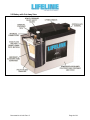
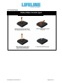
TECHNICAL MANUAL For Lifeline® Batteries Manufactured by: Concorde Battery Corporation 2009 San Bernardino Road West Covina, CA 91790 Phone 626-813-1234 Fax 626-813-1235 www.lifelinebatteries.com Document No. 6-0101 Revision D April 14, 2014 NOTICE: The technical data contained herein has been reviewed and approved for general release on the basis that it contains no export controlled information. No part of this document may be copied or reproduced by any means, including electronic or mechanical, without written permission from Concorde Battery Corporation. DISCLAIMER: The technical data contained herein is based upon the best information available as of the latest revision date. Concorde Battery Corporation makes no warranty of merchantability, fitness for any particular purpose, or any other warranty, expressed or implied, with respect to such information, and we assume no liability resulting from its use. It is the obligation of each user of the product to determine the suitability for any particular application and to comply with the requirements of all applicable laws regarding use and disposal of this product. Copyright © Concorde Battery Corporation 2014 RECORD OF REVISIONS Revision Initial Release Rev. A Rev. B Rev. C Rev. D Document No. 6-0101 Rev. D Date 10/27/08 3/25/09 9/09/09 7/18/11 4/14/14 Page 2 of 38 SAFETY SUMMARY DANGER OF EXPLODING BATTERIES Lead acid batteries can produce explosive mixtures of hydrogen and oxygen. Take the following precautions: Never install batteries in an airtight or sealed enclosure and make sure installation is adequately ventilated. Charge batteries in accordance with the instructions given in this manual. Keep all sparks, flames and cigarettes away from batteries. Connect cables tightly to the terminals to avoid sparks. Wear proper eye and face protection when installing and servicing batteries. DANGER OF CHEMICAL BURNS Lead acid batteries contain sulphuric acid electrolyte which can cause severe burns to body tissue. Take the following precautions: Avoid contact of the electrolyte with skin, eyes or clothing. Never remove or damage vent valves. In the event of an accident, flush with water and call a physician immediately. DANGER OF BURNS IF TERMINALS ARE SHORTED Lead acid batteries are capable of delivering high currents if the external terminals are short circuited. The resulting heat can cause severe burns and is a potential fire hazard. Take the following precautions: Do not place metal objects across battery terminals. Remove all metallic items such as belt buckles, watches, bracelets and rings when installing or servicing batteries. Wear insulating gloves when installing or servicing batteries. Use insulating tools when installing or servicing batteries. DANGER OF THERMAL RUNAWAY Thermal runaway is a condition in which the battery temperature increases rapidly resulting in extreme overheating of the battery. Under rare conditions, the battery can melt, catch on fire, or even explode. Thermal runaway can only occur if the battery is at high ambient temperature and/or the charging voltage is set too high. Take the following precautions: Charge batteries in accordance with the instructions given in this manual. Do not install batteries near heat sources or in direct sunlight that may artificially elevate their temperature. Provide adequate air circulation around the batteries to prevent heat build up. Document No. 6-0101 Rev. D Page 3 of 38 Table of Contents Chapter 1 - Introduction 1.1 Company Background ……………………………………………………………………………. 5 1.2 Overview of Lifeline® AGM Technology ……………………………………………………….. 5 1.3 About this Manual ………………………………………………………………………………… 5 Chapter 2 - Battery Construction 2.1 Component Description ………………………………………………………………………….. 6 2.2 Battery with Cut Away View ……………………………………………………………………… 8 2.3 Terminal Types ……………………………………………………………………………………. 9 Chapter 3 - Technology Comparison 3.1 Lifeline® versus Flooded Batteries ……………………………………………………………… 10 3.2 Lifeline® versus Gel Batteries …………………………………………………………………… 11 3.3 Lifeline® versus other AGM Batteries ………………………………………………………….. 12 Chapter 4 - Battery Specifications 4.1 Battery Models …………………………………………………………………………………….. 13 4.2 Terminals …………………………………………………………………………………………… 13 4.3 Handles …………………………………………………………………………………………….. 13 4.4 Definition of Ratings ………………………………………………………………………………. 13 4.5 Temperature Range ………………………………………………………………………………. 13 4.6 UL Recognition ……………………………………………………………………………………. 13 4.7 Shipping Classification …………………………………………………………………………… 13 Chapter 5 - Commissioning and Servicing Instructions 5.1 Storing ……………………………………………………………………………………………… 14 5.2 Installation ………………………………………………………………………………………….. 14 5.3 Discharging ………………………………………………………………………………………… 18 5.4 Charging ……………………………………………………………………………………………. 19 5.5 Conditioning ………………………………………………………………………………………... 20 5.6 Deep Discharge Recovery ……………………………………………………………………….. 21 5.7 Capacity Testing ……………………………………………………………………………………21 5.8 Temperature Considerations …………….……………….……………………………………… 22 5.9 Servicing …………………………………….……………………………………………………… 23 5.10 Recycling …………………………………….…………………………………………………… 24 Chapter 6 - Safety Information 6.1 Release of Ignitable Gases ………………………………………………………………………. 25 6.2 Acid Exposure ………………………………………………………………………………………25 6.3 Shorting of Terminals …………………………………………………………………………….. 25 6.4 Thermal Runaway …………………………….…………………………………………………… 25 Appendix A – Glossary Appendix B – Frequently Asked Questions Appendix C – Charts and Graphs Document No. 6-0101 Rev. D Page 4 of 38 CHAPTER 1 - INTRODUCTION 1.1 Company Background Concorde Battery Corporation was founded in 1977 and is a manufacturer of premium quality lead acid batteries. Originally, Concorde’s main product emphasis was dry charged and gelled electrolyte lead acid batteries. In 1985, Concorde developed its valve regulated, absorbent glass mat [AGM] technology for use in aircraft applications. The success of this technology in the aviation market has been outstanding. Concorde is now the largest manufacturer of valve regulated lead acid batteries for both commercial and military aircraft. In 1986, Concorde further developed the AGM technology for deep cycle applications. This development effort provided higher energy density (higher capacity) and better cycle life than its gelled electrolyte battery. Concorde soon discontinued the gel product line and concentrated all engineering developments on the AGM product line. In 1987, Concorde began supplying the marine and recreational vehicle market with our deep cycle AGM batteries. Over the years it has been our design expertise, quality and customer focus that has made Concorde a leader in providing the best battery available for this market segment. Concorde is committed to the proposition that the customer deserves the best performing and highest quality product. Our batteries are tailored to the application rather than make the designer/user settle for what is available. It is this commitment – to meet the needs of the customer – that sets Concorde apart. 1.2 Overview of Lifeline® AGM Technology Lifeline® AGM batteries are valve-regulated, recombinant gas, absorbed electrolyte, lead acid batteries. The cells are sealed with a pressure relief valve that prevents gases within the battery from escaping. The positive and negative plates are sandwiched between layers of glass mat consisting of a blend of glass micro fibers of varying length and diameter. This blend features superior wicking characteristics and promotes maximum retention of the electrolyte. An envelope of micro porous polyethylene surrounds each wrap of glass mat to further protect the plates from shorting. Electrolyte is absorbed and held in place by the capillary action between the fluid and the glass mat fibers. The mat is over 90% saturated with the electrolyte. By design it is not totally saturated with electrolyte, a portion is filled with gas. This void space provides the channels by which oxygen travels from the positive to the negative plates during charging. When the oxygen gas reaches the negative plate, it reacts with lead to form lead oxide and water. This reaction at the negative plate suppresses the generation of hydrogen that otherwise would come off the negative plate. In this manner, virtually all of the gas is “recombined” inside the cell, eliminating the need to add water, resulting in “maintenance free” operation. Furthermore, since the acid electrolyte is fully absorbed in the AGM separator, the battery is nonspillable even when turned upside down. 1.3 About this Manual This manual is intended to provide the customer with technical information for selecting, installing, operating, and servicing Lifeline® AGM batteries. The next Chapter provides a detailed description of the product, its design features and materials of construction. Concorde is very proud of this innovative product line and we think you will share our enthusiasm. Chapter 3 provides a comparison of Lifeline® with other lead acid technologies: floodedelectrolyte batteries, gelled-electrolyte batteries, and AGM batteries from other manufacturers. Chapter 4 presents an overview of the battery specifications for the Lifeline® product line; detailed specifications for each model are published separately. Chapter 5 provides instructions for storing, operating and servicing Lifeline® AGM batteries. Chapter 6 gives important safety information. Further technical information can be found in the Appendices. If you have additional questions beyond what is covered in this manual, please contact Concorde Battery Corporation or any of our distributors. Document No. 6-0101 Rev. D Page 5 of 38 CHAPTER 2 - BATTERY CONSTRUCTION 2.1 Component Description Refer to the battery pictorial in Section 2.2 showing a cut away view of the cell and a summary of the features and benefits. A more detailed description of the battery’s construction is given below. GRIDS - The negative grid is made of pure lead calcium alloy. The positive grid is extra thick and is made from a proprietary, pure lead-tin-calcium alloy with special grain refiners. These features improve corrosion resistance of the grid and gives the battery excellent cycling capability and float life. PLATES – The grids are pasted on state-of-the-art pasting machines to give the highest quality plates with tightly controlled weight and thickness specifications. The lead oxide paste used to make the positive plates is our high density formula. With time and use, the active material tends to soften and give less discharge capacity. The high density paste formula retards the active material softening and extends battery life. ABSORBENT GLASS MAT [AGM] SEPARATOR – The AGM is a premium blend of glass micro fibers having an optimum ratio of fine and extra fine fiber sizes. This blend features superior wicking characteristics and promotes maximum retention of the electrolyte. The AGM layer is squeezed to an optimum level of compression during assembly to provide sufficient contact with the surface of the plate over the life of the battery. This compression also promotes retention of the active material if the battery is exposed to shock or vibration conditions. POLYETHYLENE ENVELOPE – Concorde is the only manufacturer that envelopes the AGM separator with a thin layer of microporous polyethylene. The microporous layer is wrapped around the glass-matted plate and then sealed along the sides to eliminate the possibility of shorts at the edges of the plate (a common failure mode). The microporous polyethylene is more durable and puncture resistant than the AGM material alone and significantly reduces the occurrence of plate to plate shorts. INTERCELL CONNECTIONS - Massive “over the partition” fusion welds are used which increase the strength of the intercell connection. This minimizes the possibility of open welds and provides a low resistance connection between cells. Other manufacturers use “through the partition” spot welded construction that inserts a weak point into the assembly because of the small cross section area and the difficulty of making a reliable weld and leak proof construction. HIGH IMPACT, REINFORCED CONTAINER & COVER – The battery container and cover are made of a thick walled polypropylene copolymer. This material provides excellent impact resistance at extreme low temperatures and minimizes bulging at high temperatures. COVER-TO-CONTAINER SEAL - The batteries use an epoxy-filled tongue and groove seal between the cover and container. Most other manufacturers heat seal their cover to the container. The epoxy-filled tongue and groove seal is a far stronger than a heat seal and will not separate in high or low temperature extreme applications. Document No. 6-0101 Rev. D Page 6 of 38 PRESSURE RELIEF SAFETY VALVE - Each cell in the battery employs a pressure relief safety valve. The valve is designed to release excess pressure that builds up over time to vent the small quantity of gasses that do not recombine inside of the battery. Once the pressure is released, the valve automatically re-seals. The gasses that escape are mainly oxygen and some hydrogen, and these gasses rapidly dissipate into the atmosphere. TERMINALS - Lifeline® AGM batteries are available in a variety of terminal configurations. Most terminal types are made of copper alloy which provide a long lasting, low resistance electrical connection. The copper alloy terminals are non corrosive, unlike lead terminals. Additionally, the copper alloy terminals offer increased environmental protection and personal safety in comparison to commonly used lead terminals. Refer to the pictorial in Section 2.3 to see a detailed view of the various terminal types that are available. HANDLES – Lifting handles are incorporated into all Lifeline® AGM batteries. This provides easier handling for lifting, carrying and installation. Document No. 6-0101 Rev. D Page 7 of 38 2.2 Battery with Cut Away View Document No. 6-0101 Rev. D Page 8 of 38 2.3 Terminal Types Document No. 6-0101 Rev. D Page 9 of 38 CHAPTER 3 - TECHNOLOGY COMPARISON 3.1 Lifeline® versus Flooded Batteries Flooded-electrolyte lead acid batteries have been around since 1859 and tend to be less expensive than AGM or Gel batteries. However, they have major deficiencies compared to AGM or Gel batteries. For instance, deep cycle flooded lead acid batteries contain antimony in the grid alloy which causes a high rate of self discharge and rapid water loss due to gassing reactions. The escape of hydrogen and oxygen from the battery represents a serious safety hazard if the gasses are not ventilated properly. In flooded batteries, replacing the antimony lead alloy with calcium lead alloy reduces the amount of gassing and water loss, but the cycle life is much lower and they are no longer considered deep cycle batteries. Electrolyte stratification can occur in all types of flooded batteries. As the battery is discharged and charged, the concentration of acid becomes higher at the bottom of the cell and becomes lower at the top of the cell. The low acid concentration reduces capacity at the top of the plates, and the high acid concentration accelerates corrosion at the bottom of the plates and shortens the battery life. Although stratification can be minimized by raising the charging voltage so that the increased gassing agitates the electrolyte, this will accelerate the water loss and watering frequency. One other difference is that flooded batteries can not tolerate freezing temperatures when in the discharged state, whereas AGM batteries are not damaged by freezing temperatures. The following table provides a side by side comparison of Lifeline® AGM and flooded deep cycle batteries. Table 3-1. Comparison of Lifeline® AGM Batteries with Flooded Deep Cycle Batteries Characteristic Lifeline® AGM Battery Flooded Deep Cycle Battery 1 to 3% per month – remains 5-10% per month when new – Self Discharge stable over life. Water Addition Never. Hydrogen Gas Emissions Negligible unless severely overcharged. Electrolyte Spillage Electrolyte Stratification Nonspillable in all orientations – electrolyte is retained in AGM separator. No stratification occurs. Tolerance to freezing temperatures Resistant to damage when frozen. Document No. 6-0101 Rev. D increases drastically with age due to antimony contamination of the negative plate. Frequent – increases dramatically with age due to antimony contamination of the negative plate. Significant volume is generated and must be ventilated to prevent explosion. Spills when tilted, inverted, or cracked. Stratification occurs when operated at low charging voltages or in taller batteries. Battery destroyed when frozen. Page 10 of 38 3.2 Lifeline® versus Gel Batteries Gel batteries have been commercially available since the early 1970’s and are still offered by some manufacturers. Concorde manufactured gel batteries for many years before developing the AGM technology and, therefore, is aware of inherent deficiencies associated with gel batteries. The gel product employs a highly viscous, semisolid mixture of silica gel and dilute sulfuric acid in a colloidal suspension as an electrolyte. The electrolyte is difficult to keep homogeneous and the solid silica can separate from the acid, creating a “flooded” battery. Handling and vibration exposure are operational factors that can cause the silica and acid mixture to separate as there is no chemical bond. In high temperature environments, the semisolid electrolyte develops cracks and voids that reduce contact between the plates and causes the battery to lose capacity. This same effect gradually occurs even at normal room temperatures. By contrast, AGM batteries employ a glass micro fiber mat separator that holds the liquid electrolyte like a sponge. Shrinkage of the separator does not occur as the battery ages and the electrolyte remains in direct contact with the plates. The electrolyte remains immobilized even when the battery is exposed to severe vibration, so electrolyte spillage or leakage is prevented. Since it is easier to fill a container with a liquid than a semi-solid, AGM batteries require less space between battery plates. The closer plate spacing gives the AGM battery a lower internal resistance, making it more charge efficient and giving better power performance on discharge, especially at low temperatures. Gel batteries are also more sensitive to charging voltage. If the charging voltage is not controlled within a very tight range relative to the battery’s temperature, the life of the battery will be adversely affected. For example, one manufacturer of gel batteries claims that if the charging voltage is 0.7V higher than the recommended level, the cycle life will be reduced by 60 percent. The reason for this effect is the limited oxygen recombination capability of gelled batteries. Lifeline® AGM batteries are more forgiving in overcharge conditions and their ability to recombine the hydrogen and oxygen gases back into water is more efficient. With Lifeline® AGM batteries, tests have shown that increasing the charging voltage 1.0V above the recommended charging voltage results in only a 23% reduction in the cycle life. The charge acceptance of gel batteries is also less than that of Lifeline® AGM batteries. This means it takes longer to recharge gel batteries. As an example, tests have shown that when discharged to 50% of rated capacity (fairly common in a deep cycle applications), gel batteries took twice as long to reach full charge as compared to Lifeline® AGM batteries. The following table provides a side by side comparison of Lifeline® AGM and gel batteries: Document No. 6-0101 Rev. D Page 11 of 38 Table 3-2. Comparison of Lifeline® AGM Batteries with Gel Batteries Characteristic Lifeline® AGM Battery Gel Batteries Excellent – AGM acts like a flexible Prone to solid / liquid separation leading Electrolyte Stability sponge. High Rate Performance Excellent due to low internal impedance. Sensitivity to Charging Voltage Levels Moderately sensitive. Life is somewhat reduced if charged outside of recommended charge voltage levels. Excellent. Battery can be fully charged in 2 hours if high inrush current is available. Charge Acceptance Rate to spillage / spewage of acid and premature failure. Electrolyte loses contact with plates due to cracks and voids as the battery ages, especially at higher ambient temperatures. Inferior. Plate spacing must be greater to allow for gel passage during filling. Gel adds to impedance, especially at low temperatures. Very Sensitive. Life is greatly reduced if charged outside of recommended charge voltage levels. Inferior. Must limit in rush current and charge time is at least twice as long to reach full charge. 3.3 Lifeline® versus other AGM Batteries Lifeline® AGM batteries have been specifically designed for true deep cycle, long service life capability in adverse temperature and handling conditions. Concorde uses extra thick positive plates, high density paste, thick AGM separator layers encased within a microporous polyethylene envelope, thick walled containers with epoxy-sealed covers. A side by side comparison of Lifeline® AGM batteries with typical AGM batteries from other manufacturers is provided in the following table: Table 3-3. Comparison of Lifeline® AGM Batteries with Other AGM Batteries Characteristic Lifeline® AGM Battery Other AGM Batteries Extra thick grids (typically 0.095” or Thinner grids, typically 0.045 to 0.060”. Positive Grids Pasted Plates AGM Separator Microporous polyethylene separators Intercell connections greater) and extra thick plates (typically 0.105” or greater), for long cycle and float life. High density positive paste for long cycle life. Extra thick for maximum electrolyte reserve. Premium grade of AGM with extra fine fibers for long life. Envelopes the positive plate to prevent shorting due to shock, vibration and dendrites Massive over the partition connectors provide a robust, leak proof connection with low voltage loss. Battery Terminals Copper alloy – low electrical resistance and no exposed lead. Container Thick wall for rigid support of cell elements and high compression of AGM separator. Cover is epoxied to container – high strength bond for reliable operation at temperature extremes. Cover Seal Document No. 6-0101 Rev. D Lower density, resulting in lower cycle life. Thinner material used. Inferior grade of AGM without the extra fine fiber content. Not present, AGM is the only separator protecting the plates. Inferior through the partition welds have less cross sectional area, provide weaker structural connection, and are leak prone. Lead alloy - higher in electrical resistance and user is exposed to lead contamination. Thinner walls, less support of cell elements and lower compression of AGM separator. Cover is heat sealed (melted) to container – prone to separation and leakage at temperature extremes. Page 12 of 38 CHAPTER 4 - BATTERY SPECIFICATIONS 4.1 Battery Models The Lifeline® Series consists of deep cycle as well as engine starting batteries. Capacities of the deep cycle batteries range from 33 to 1200 ampere hours (rated at the 20 hour rate) and a variety of 2-volt, 6-volt and 12-volt models are available. Ratings of the starting batteries range from 550 amperes to 810 amperes (CCA at 0°F) and these are only available in 12 volt models. Refer to the battery specification sheet (published separately) for a complete listing of the mechanical and electrical specifications for each battery model. 4.2 Terminals Standard Terminals: The following table shows the standard type of terminal used on each battery model: Table 4-1. Battery Terminals Battery Model Standard Terminal Type GPL-24T, GPL-2400T, GPL-27T, GPL-2700T, GPL-31T, GPL-3100T, GPL-31XT, GPL-31T-2V GPL-4DL, GPL-8DL GPL-4DA, GPL-8DA GPL-1400T, GPL-30HT, GPL-4CT, GPL-6CT, GPL-L16T, GPL-4CT-2V, GPL-6CT-2V, GPL-L16T-2V GPL-U1T Marine Terminal (Copper Alloy) Positive = M10 and Negative = M8 L-Blade Terminal (Copper Alloy) with M8 Hardware SAE Automotive Post (Lead) M8 Threaded Insert (Copper Alloy) M6 Threaded Insert (Copper Alloy) Optional Terminals: The 2 and 6 volt models are available with marine terminals on a special order basis. Terminal Hardware: When requested, batteries are supplied with silicon bronze bolts, nuts and washers as required for installation. Terminal Torque Values: Use 35 in-lbs / 4.0 nm for M6. Use 70 in-lbs / 7.9 nm for M8 and M10. 4.3 Handles All batteries include lifting handles, either built into the cover, dual ropes attached to the cover, or a single plastic handle attached to brackets on the sides of the container. 4.4 Definition of Ratings Capacity ratings are after 15 cycles per BCI specifications and are stated at 77°F (25°C) to 1.75 volts per cell. 4.5 Temperature Range Storage (when fully charged): -67°F (-55°C) to 122°F (50°C) Operating: -40°F (-40°C) to 160°F (71°C). 4.6 UL Recognition All Lifeline® AGM batteries meet the requirements of UL® 1989 (Standby Battery) and are UL recognized under UL File Number MH-17983. 4.7 Shipping Classification Lifeline® AGM batteries have been tested and determined to be in compliance with the vibration and pressure differential tests in accordance with DOT 49 CFR 173.159(d) and Special Provision A67 of the International Air Transport Association (IATA) Dangerous Goods regulations. As such, they are classified as a “NONSPILLABLE BATTERY” and can be shipped as non-hazardous material by any means. To comply with DOT shipping regulations, the battery must be packaged to protect against short circuits and the battery and outer packaging must be plainly and durably marked “NONSPILLABLE” or “NONSPILLABLE BATTERY”. Document No. 6-0101 Rev. D Page 13 of 38 CHAPTER 5 - COMMISSIONING AND SERVICING INSTRUCTIONS 5.1 Storage Lifeline® Batteries are charged at the factory and are ready for installation when they are received. Batteries may be stored prior to installation for up to 2 years, provided they are boost charged as described below. Batteries should be stored in the coolest environment available, preferably not exceeding 68°F (20°C). The higher the temperature, the faster the battery will self-discharge and require boost charging. See Appendix C for data on storage time versus temperature. While in storage, batteries should be boost charged every 90 days or when the open circuit voltage (OCV) drops to 12.5 volts for a 12 volt battery (6.25 volts for a 6 volt battery and 2.08 volts for a 2V battery). This OCV corresponds to approximately 75% state of charge. Boost charge batteries using a constant voltage charger set at 14.4 to 15.0 volts for a 12 volt battery (7.2 to 7.5 volts for a 6 volt battery and 2.40 to 2.50 for a 2 volt battery). The boost charge should be applied until the charging current falls below 0.5 percent of the battery’s 20 hour rated capacity (0.5 amps for a 100 Ah battery). 5.2 Installation Be sure there is adequate ventilation in the area where the batteries are to be installed (see Chapter 6). Batteries may be installed in any orientation except upside down (i.e., terminals facing the earth). The space surrounding adjacent batteries should be at least 0.25 inch to permit airflow around each battery. Always use batteries of the same size and condition in multibattery installations. When replacing batteries, it is best to replace the entire set of batteries so they remain balanced. Connect batteries using cabling that is sized for the maximum load of the system. The voltage drop on the cables during charging should not exceed 0.2 volts at full output. Protect the battery terminals from shorting during installation. Batteries may be connected in series (voltage adds, capacity stays the same), in parallel (capacity adds, voltage stays the same), or a combination of series and parallel (voltage and capacity adds). Each of these connection options are illustrated in Figures 5-1 through 5-3, respectively. Document No. 6-0101 Rev. D Page 14 of 38 Figure 5-1. Series Connection Figure 5-2. Parallel Connection Figure 5-3. Series/Parallel Connection Document No. 6-0101 Rev. D Page 15 of 38 Connection options for 4-terminal batteries are illustrated in Figures 5-4 through 5-8. For low rate applications (current levels less than 400 amperes), only two of the four terminals need to be connected, but it is still best to use all four terminals for redundancy. For high rate applications (current levels greater than 400 amperes), all four terminals should be connected. Figure 5-4. Series Connection for 4-Terminal Batteries (Low Rate Applications Only) Figure 5-5. Series Connection for 4-Terminal Batteries (Low or High Rate Applications, Option A) Figure 5-6. Series Connection for 4-Terminal Batteries (Low or High Rate Applications, Option B) Document No. 6-0101 Rev. D Page 16 of 38 Figure 5-7. Series/Parallel Connection for 4-Terminal Batteries (Low Rate Applications Only) NOTE: Cables A, B and C carry different current levels and should be sized accordingly. In this example, the current in Cable B is 2 times that of Cable A and the current in Cable C is three times that of Cable A. Document No. 6-0101 Rev. D Page 17 of 38 Figure 5-8. Series/Parallel Connection for 4-Terminal Batteries (Low or High Rate Applications) 5.3 Discharging Discharge data for Lifeline® AGM batteries are given in Appendix C. The capacity delivered by the battery depends on the rate of discharge as well as the battery temperature. The battery will deliver less capacity as the discharge rate increases and less capacity as the temperature is lowered. Graphs are provided in Appendix C to quantify these effects. Peukert plots (Amps vs Time) are also included, along with formulas for calculating the current that can be removed or any discharge time from 0.5 hours to 120 hours. To calculate the discharge time for a specified amperage, these formulas can be inverted as follows: A = C x T -n 1/n -1/n T=C xA (A = Amps, T = Time in hours, C & n are constants specific for each battery model) In general, batteries should be sized such that the rated capacity is at least twice the capacity required by the load. For example, if 100 Ah is required on average, select at least a 200Ah battery. This approach will limit the average depth of discharge to 50% and will dramatically extend the life of the battery (see chart of Cycle Life versus Depth of Discharge in Appendix C). Document No. 6-0101 Rev. D Page 18 of 38 5.4 Charging Charging Lifeline® AGM batteries is a matter of replacing the energy removed during discharge plus a little extra to make up for charging inefficiency. The amount of energy necessary for complete recharge depends on the depth of discharge, rate of recharge, and temperature. Typically, between 102% and 110% of the discharged ampere-hours must be returned for full recharge. The most efficient method of charging Lifeline® AGM batteries is to use a 3 stage charging profile. In the first stage, a constant current is applied until the voltage reaches a pre-set limit. The first stage is often called the Bulk charging stage. In the second stage, the voltage is held constant at the same pre-set limit until the charging current tapers to a very low value, at which point the battery is fully charged. The second stage is often called the Absorption charging stage. A voltage limit of 14.3 volts ± 0.1 volts (7.15 ± 0.05 volt for a 6 volt battery) should be used when the battery temperature is 77°F (25°C). The battery is fully charged when the current drops below 0.5% of the battery’s rated capacity (0.5A for a 100Ah battery). In the third stage, the charging voltage is reduced to a lower value that minimizes the amount of overcharge, while maintaining the battery at 100% state of charge. This third stage is often called the Float charging stage. A float voltage of 13.3 ± 0.1 volts (6.65 ± 0.05 volts for a 6 volt battery) should be used when the battery temperature is 77°F (25°C). The charging voltages at other temperatures can be determined from the following table: Table 5-1. Charging Voltage at Different Temperatures for a 12 Volt Battery* Temp °F -40 -30 -20 -10 0 10 20 30 40 50 60 Absorption Voltage 16.88 16.58 16.30 16.03 15.78 15.54 15.31 15.10 14.90 14.72 14.56 Float Voltage 15.86 15.56 15.28 15.01 14.76 14.52 14.29 14.08 13.88 13.70 13.54 Temp °F 70 77 80 90 100 110 120 130 140 150 160 Absorption Voltage 14.41 14.30 14.27 14.15 14.04 13.95 13.87 13.81 13.76 13.73 13.71 Float Voltage 13.39 13.30 13.25 13.13 13.02 13.00 13.00 13.00 13.00 13.00 13.00 * For a 6 volt battery, divide the voltage by 2. For a 2 volt battery, divide the voltage by 6. The charging current during the Bulk stage should be set as high as practical; higher current levels mean faster recharge time. Due to the low impedance design, Lifeline® batteries can tolerate in-rush current levels as high as 5C (500A for a 100Ah battery). The time to reach full charge at temperatures in the range of 68 to 86°F (20-30°C) can be estimated from the following equation: Time to Reach Full Charge = [(DOD/100) x Rated Capacity (Ah) ÷ Rated Output of Charger (Amp)] + 2 hours. For example, charging a 100Ah battery at 50% DOD with a 25A charger would take: [(50/100) x 100 ÷ 25] + 2 = 4 hours to reach full charge. If a 10A charger is used, it would take: [(50/100) x 100 ÷ 10] + 2 = 7 hours to reach full charge. Document No. 6-0101 Rev. D Page 19 of 38 Note that the above formula is approximate and the full charge state should be verified using the criteria given above (current drops below 0.5% of rated capacity). If the recharge does not return 102% to 110% of the discharged capacity, the battery’s state of charge will gradually “walk down” as it is cycled leading to premature failure. Therefore, it is important to verify that the battery is not being undercharged. For repetitive deep cycling applications (deeper than 50% DOD), chargers should have an output current of at least 0.2C (20 Amps for a 100 Ah battery). If the output current is less than this value, the cycle life of the battery may be negatively affected. If a charger with at least 0.2C output is not practical, an alternative charge profile using a low rate constant current stage at the end of the absorption stage will normally improve the cycle life. The constant current stage should be at 0.02C (2 Amps for a 100Ah battery) for no more than one hour. Some types of battery chargers allow the user to input the Peukert constant to obtain an optimum charging profile. For Lifeline® batteries, the recommended value of the Peukert constant is n = 1.12. 5.5 Conditioning Conditioning should only be done when the battery is showing symptoms of capacity loss due to extended time in a partial or low state of charge condition. This could be caused, for example, by low charging voltage for an extended number of charge cycles, or by repeatedly charging to only 90% state of charge. NOTE: Some chargers use the term Equalizing Charge instead of Conditioning Charge. An Equalizing Charge is generally applied to flooded lead acid batteries that are susceptible to acid stratification. However, an Equalizing Charge may be used to provide a Conditioning Charge for Lifeline® batteries as described below. To apply a conditioning charge, first go through the normal charge cycle to bring the battery to full charge. The conditioning charge should then be applied by charging for 8 hours. At 77°F (25°C), the conditioning voltage should be set at 2.58 VPC (15.5 volts for a 12 volt battery). The conditioning voltage at other temperatures is shown in Table 5-2. By using the temperaturecompensated conditioning voltage, batteries that are not in controlled temperature environments may be conditioned without bringing them to room temperature. If temperature compensation is not available, it is best to bring the battery as close to room temperature as possible before applying the conditioning charge. Table 5-2. Conditioning Voltage at Different Temperatures for a 12 Volt Battery* Conditioning Conditioning Temperature °F Voltage Temperature °F Voltage -40 18.05 70 15.58 -30 17.75 77 15.48 -20 17.47 80 15.44 -10 17.20 90 15.32 0 16.95 100 15.21 10 16.71 110 15.12 20 16.48 120 15.04 30 16.27 130 14.98 40 16.07 140 14.93 50 15.89 150 14.90 60 15.73 160 14.88 * For a 6 volt battery, divide the voltage by 2. For a 2 volt battery, divide the voltage by 6. Document No. 6-0101 Rev. D Page 20 of 38 5.6 Deep Discharge Recovery Batteries that have been in storage for long periods of time without boost charging, or have been kept deeply discharged for an extended time, may need to be charged at constant current instead of constant voltage to restore capacity. The following procedure is effective if the batteries are not too badly sulfated. WARNING: This procedure should only be done in a well ventilated area because a significant amount of hydrogen gases may be released from the battery. 1. 2. 3. 4. Stabilize the battery at 68-86°F (20-30°C) for at least 24 hours prior to testing. Charge at a constant current of 5% of rated (20 hour) capacity until the voltage reaches 15.6 volts (7.8 volts for a 6 volt battery), then continue charging at this rate for an additional 4 hours. Note that the charging voltage may get as high as 18.0 volts (9.0 volts for a 6 volt battery), so the power supply must be capable of outputting this level to maintain constant current. This constant current charge may take 16 to 20 hours. CAUTION: If the battery becomes hot (above 130°F/55°C) during this charge, stop the current and allow the battery to cool to room temperature before continuing the charge. Perform a capacity test as described in Section 5.7. If the capacity is less than 80% of the battery’s rating, steps 2-3 may be repeated up to 2 times. Be sure to start the constant current charge with a fully discharged battery. NOTE: The above procedure should be performed by an experienced battery maintenance facility utilizing the proper charging and test equipment. For information regarding Concorde’s recommended test equipment go to: www.concordebattery.com/accessories.php. 5.7 Capacity Testing To determine the actual capacity of a Lifeline® AGM battery relative to its rated capacity, a full discharge test should be performed. Although there are various battery testers available on the market, such as carbon pile testers, impedance meters, conductance meters, and others, these testers are not reliable in determining the battery’s actual capacity. To determine the battery’s actual capacity relative to its rated capacity, use the following procedure: 1. 2. 3. 4. 5. 6. Stabilize the battery at 68-86°F (20-30°C) for at least 24 hours. Bring the battery to full charge as described in Sections 5.4, 5.5 or 5.6 as applicable. Discharge the battery at a constant current of 25 amperes until the voltage falls to 10.5 volts (5.25 volts for a 6 Volt battery). Record the discharge time in minutes. Compare the measured discharge time to the published 25A rating (reserve capacity minutes) for the battery. If the battery delivers less than 80% of the rated capacity the conditioning procedure given in Section 5.5 should be attempted and the battery capacity should be retested. If the battery delivers less than 50% of its rated capacity, it should be replaced. However, the user should determine the amount of capacity needed for their particular application and adjust the pass/fail threshold accordingly. NOTE: The above procedure should be performed by an experienced battery maintenance facility utilizing the proper charging and test equipment. For information regarding Concorde’s recommended test equipment go to: www.concordebattery.com/accessories.php. Document No. 6-0101 Rev. D Page 21 of 38 5.8 Temperature Considerations The temperature of the battery has a significant impact on its performance and life capability. Battery capacity is reduced significantly in cold temperatures. For example, a battery that operates continuously at -18ºC (0º F.) will only provide about 60% of its normal room temperate capacity. Appendix C provides a chart of capacity versus temperature at various discharge rates. Battery life is also affected by temperature. As a rule of thumb, the battery life decreases by 50% for every 10⁰C rise in temperature. Thus, a battery that lasts 6 years at 25⁰C will last 3 years at 35⁰C, 1.5 years at 45⁰C, and 0.75 years at 55⁰C. It should be realized that the temperature of the battery itself and ambient temperature can be vastly different. While ambient temperatures can change very quickly, battery temperature change is much slower. This is due to the large thermal mass of the battery. It takes time for the battery to absorb temperature and it takes time for the battery to relinquish temperature. If the battery is exposed to cold climates, the state of charge should be kept at a maximum to prevent freezing of the electrolyte. A fully charged battery will not freeze even under the coldest weather conditions, but a discharged battery will freeze even when moderately cold. Table 6-2 gives the freezing point of electrolyte at various states of charge. Frozen batteries are not capable of charging or discharging except at very low rates, and may be permanently damaged by expansion of the electrolyte. If a battery becomes frozen, it should be thawed by placing it at room temperature for at least 24 hours, and then charged in accordance with Sections 5.4, 5.5 or 5.6 as applicable. However, if the battery container has any evidence of cracking, the battery is no longer serviceable and should not be used. Table 6-2. Electrolyte Freezing Point at Various Battery States of Charge Battery State of Charge (%) 100% 75% 50% 25% 0% Document No. 6-0101 Rev. D Approximate Electrolyte Freezing Temperature -70°C (-94°F) -47°C (-53°F) -25°C (-13°F) -13°C (9°F) -6°C (21°F) Page 22 of 38 5.9 Servicing Lifeline® AGM batteries do not need electrolyte additions as do flooded lead-acid batteries, but periodic servicing is essential to assure continued integrity of the battery system. Servicing should include good record keeping to document the life history of the battery system and to identify whether corrective action needs to be taken. The following servicing schedule is recommended: Installation 1. Within the first week of operation, put the battery system on a full charge cycle and record the following parameters (baseline readings): a. Charger amperage output b. Absorption voltage at battery system terminals c. Float voltage at battery system terminals d. Ripple voltage at battery system terminals (see Note 1) e. Voltage of each battery when charger is in float mode (see Note 2) f. Ambient temperature 2. Allow the battery system to discharge until it reaches the low voltage disconnect, and record the following parameters: a. Run time b. Capacity delivered (Ampere-hours) c. Average DC load (amperes) d. Endpoint voltage at battery system terminals 3. After discharging, return the battery to a fully charged condition as soon as possible. Quarterly 1. Inspect each battery terminal for any corrosion deposits. If present, remove with a wire brush, neutralize with a baking soda solution, dry, and then apply NO-OX-ID grease. 2. Record the following parameters with the battery on float charge: a. Float voltage at battery system terminals b. Voltage of each battery (see Note 2) c. Ambient temperature Yearly 1. Put the battery on a full charge cycle and record the following parameters: a. Charger amperage output b. Absorption voltage at battery system terminals c. Float voltage at battery system terminals d. Ripple voltage at battery system terminals (see Note 1) e. Voltage of each battery when charger is in float mode (see Note 2) f. Ambient temperature 2. Allow the battery system to discharge until it reaches the low voltage disconnect, and record the following parameters: a. Run time b. Capacity delivered (Ampere-hours) c. Average DC load (amperes) d. Endpoint voltage at battery system terminals 3. After discharging, return the battery to a fully charged condition as soon as possible. Document No. 6-0101 Rev. D Page 23 of 38 NOTES: (1) Excessive ripple voltage will negatively impact battery life. Maximum recommended ripple voltage (peak to peak) is 0.5% of the float voltage setting. (2) A large variation of individual float voltages in a new battery system is normal because of variations in oxygen recombination efficiency due to slight variations of acid saturation within the AGM. As the battery ages, the variation should drop to lower values. Excessive variation of float voltages after the first 1-2 months is an indication that the batteries may be out of balance. If individual battery voltage readings during float charge vary by more than 0.10 volt per cell (0.10 volt for 2V batteries, 0.30 volt for 6V batteries, and 0.6 volt for 12V batteries), then a conditioning charge per Section 5.5 is recommended. 5.10 Recycling Batteries that have reached the end of their service life should be returned to a local or regional collection center for recycling. All local regulations and ordinances must be followed. Never discard Lifeline® AGM batteries in the trash or in a landfill. The recycle rate of lead acid batteries is close to 100% and this is very good for the environment! Document No. 6-0101 Rev. D Page 24 of 38 CHAPTER 6 - SAFETY INFORMATION There are four main safety hazards associated with the use of any valve regulated lead acid (VRLA) battery. These hazards are: a) Release of ignitable gas, b) Exposure to acid, c) Shorting of terminals, d) Thermal runaway. This chapter provides a description of each of these hazards and means to mitigate them. 6.1 Release of Ignitable Gasses All lead acid batteries, including VRLA batteries, produce hydrogen and oxygen gases during normal charging. Even though VRLA batteries are designed to recombine these gases internally, the recombination efficiency is less than 100%. Small amounts of hydrogen and oxygen are released from the pressure relief valve during charging. Normally, the hydrogen gas dissipates very rapidly and never reaches a concentration level that is hazardous. However, if the battery is installed in an enclosure with minimal airflow, the concentration of hydrogen could build up to a high enough concentration to be of concern. Hydrogen can ignite at concentrations as low as 4% in air. For this reason, never install a Lifeline® AGM battery in a sealed or an airtight container. 6.2 Exposure to Acid All lead acid batteries contain sulfuric acid in the electrolyte, which can cause chemical burns to body tissue. Although Lifeline® AGM batteries are classified as Nonspillable, exposure to the electrolyte is possible under extreme conditions (e.g., if the battery is cracked open or crushed). In the event that electrolyte is displaced from the battery, avoid contact with the skin, eyes and clothing. In the event of an accident, flush with water and call a physician immediately. 6.3 Shorting of Terminals Lifeline® AGM batteries have very low internal impedance and therefore are capable of delivering high currents if the external terminals are short circuited. The resulting heat can cause severe burns and is a potential fire hazard. Accidentally placing metal objects across the terminals can result in severe skin burns. It is a good practice to remove all metallic items such as belt buckles, watches, bracelets and rings when installing or servicing batteries. As a further precaution, insulating gloves should be worn and only insulated tools should be used when installing or servicing batteries. 6.4 Thermal Runaway Thermal runaway is a condition in which the battery temperature increases rapidly resulting in extreme overheating of the battery. Under rare conditions, the battery can melt, catch on fire, or even explode. Thermal runaway can only occur if the battery is at high ambient temperature and/or the charging voltage is set too high. As the battery accepts current, its internal temperature rises. The rise in temperature reduces the battery impedance, causing it to accept more current. The higher current further heats the battery, and so on, causing the battery temperature to “runaway”. An upper limit will eventually be reached when the electrolyte starts to boil, but once the electrolyte has boiled away, the temperature can climb even further to the point of plastic meltdown and possible fire. As of this writing, Concorde does not know of any Lifeline® AGM batteries that have failed due to thermal runaway. To preclude the possibility of thermal runway, the charging instructions in Chapter 5 should be carefully followed, especially if the battery will be subjected to high ambient temperatures. Batteries should not be installed near heat sources or in direct sunlight that may artificially elevate their temperature. Also, there should be adequate air circulation around the batteries to prevent heat build-up. Document No. 6-0101 Rev. D Page 25 of 38 APPENDIX A – GLOSSARY OF BATTERY TERMS AGM - Stands for Absorbed Glass Mat. This is the separator system used in all Lifeline® AGM batteries. Active Material - Electrode material which produces electricity during its chemical conversion. In the positive plate it is lead dioxide. In the negative plate, it is sponge lead. Ampere - Unit of electrical current abbreviated as amps or A. Amps = Watts/Volts or A = W/V. Ampere Hour (Ah) - The capacity of a storage battery is measured in ampere hours. One ampere hour is defined as a current flow of one ampere for a period of one hour. Five ampere hours means a current flow of one ampere for five hours, a current flow of 2 1/2 ampere for 2 hours, or any multiple of current and time that will result in five. This relationship can be expressed as follows: Capacity (Ampere hours)= I*T, where I is the current (in amperes) and T is the time (in hours). The capacity of a storage battery is based on a given discharge rate, since the capacity will vary with the rate of discharge. Boost Charge - A charge applied to a battery which is already near a state of full charge, usually of short duration. Capacity - The quantity of electricity delivered by a battery under specified conditions, usually expressed in ampere hours. Capacity, Rated - A designation by the battery manufacturer which defines the performance of a new battery at a defined rate of discharge. For Lifeline® AGM batteries, the rated capacity is based on the 20 hour rate. Capacity, Residual - Capacity remaining at particular point in time and set of operating conditions, usually at a partial state of charge condition. Cell Reversal - Reversing of polarity within a cell in a multi cell battery due to over discharge. Charge - The conversion of electrical energy from an external source, into chemical energy within a cell or battery. Charge Rate - The rate at which current is applied to a cell or battery to restore its capacity. Charge Retention - The ability of a charged cell or battery to resist self discharge. Charge, State of - Ratio of the amount of capacity remaining in a battery to the capacity when fully charged. A battery at 25% state of charge has 25% capacity remaining versus what it could give if fully charged. Charger - Device capable of supplying electrical energy to charge a battery. Charging - The process of converting electrical energy to stored chemical energy. The opposite of discharging. Charging Efficiency - Ratio of the Ampere hours delivered on discharge to the Ampere hours needed to fully charge a battery. Conditioning - A special constant current charge process used to restore a battery’s capacity after extended storage periods or deep discharge exposure. Also known as reconditioning. Constant Current (CC) Charge - Charging technique where the output current of the charge source is held constant. Warning! This procedure may damage the battery if performed on a repetitive basis. Constant Voltage (CV) Charge - Charging technique where the output voltage of the charge source is held constant and the current is limited only by the resistance of the battery and / or the capacity of the charge source. Also known as Constant Potential (CP) charge. Document No. 6-0101 Rev. D Page 26 of 38 Current - The rate of flow of electricity. The movement of electrons along a conductor. It is comparable to the flow of a stream of water. The unit of measurement is an ampere. Cut Off Voltage - Battery voltage reached at the termination of a discharge. Also known as end point voltage or EPV. Cycle - One sequence of discharge and charge. Cycle Life - The total number of charge/discharge cycles before the battery reaches end of life (generally 80% of rated capacity). Deep Discharge - Withdrawal of more than 80% of the rated capacity. Depth Of Discharge - The portion of the capacity taken out during a discharge, expressed as a percent of rated capacity. Discharge - The conversion of the chemical energy of a cell or battery into electrical energy and withdrawal of the electrical energy into a load. End Of Life - The stage at which the battery fails to deliver acceptable capacity (typically 80% of nameplate rating). Float charge - A method of maintaining a battery in a charged condition by continuous, long term, constant voltage charging at level sufficient to balance self-discharge. Gassing - The evolution of gas from one or more of the electrode plates in a cell. Gassing commonly results from local action (self discharge) or from the electrolysis of water in the electrolyte during charging. Internal Impedance - Same as Internal Resistance. Internal Resistance - The opposition or resistance to the flow of a direct electric current within a cell or battery; the sum of the ionic and electronic resistance of the cell components. Its value varies with the current, state of charge, temperature, and age. With an extremely heavy load, such as an engine starter, the cell voltage may drop significantly. This voltage drop is due to the internal resistance of the cell. A cell that is partly discharged has a higher internal resistance than a fully charged cell, hence it will have a greater voltage drop under the same load. This change in internal resistance is due to the accumulation of lead sulfate in the plates. Open Circuit Voltage - The voltage of a battery when it is not delivering or receiving power, and has been at rest long enough to reach a steady state (normally, at least 4 hours). Overcharge - The forcing of current through a cell after all the active material has been converted to the charged state. In other words, charging continued after 100% state of charge is achieved. The result will be the decomposition of water in the electrolyte into hydrogen and oxygen gas, heat generation, and corrosion of the positive electrode. Self Discharge - The decrease in the state of charge of a cell or a battery, over a period of time, due to internal electrochemical losses. Series Connection - Voltage of the system is cumulative. Capacity stays the same. Shelf Life - The period of time (measured from date of manufacture) at a specified storage temperature after which the cell or battery needs to be boost charged so it does not suffer permanent capacity loss. State Of Charge (SOC) - The available ampere hours in a battery at any given time relative to its full charge capacity. State Of Health (SOH) - The available ampere hours in a battery when fully charged relative to its rated capacity. Sulfation - Refers to the formation of hard lead sulfate crystals in the plates that are difficult, if not impossible, to reconvert to active material. Temperature, Ambient - The average temperature of the battery's surroundings. Document No. 6-0101 Rev. D Page 27 of 38 Temperature, Cell - The average temperature of the battery's internal components. Trickle Charging - Method of charging in which the battery is either continuously or intermittently connected to a constant current charging source to maintain the battery in a fully charged condition. Not recommended for use with Lifeline® AGM batteries. Vent Valve - A normally closed check valve located in a cell which allows the controlled escape of gases when the internal pressure exceeds its rated value. Venting - A release of gas either controlled (through a vent) or accidental from a battery cell. Document No. 6-0101 Rev. D Page 28 of 38 APPENDIX B – FREQUENTLY ASKED QUESTIONS (FAQ’S) What does AGM stand for? It stands for Absorbed Glass Mat, the type of separator used in all Lifeline® AGM batteries. What is the difference between AGM batteries and Gel batteries? Both AGM and Gel batteries utilize oxygen recombination and pressure relief valves to minimize water loss and allow maintenance-free operation. That is where the similarities end. AGM batteries have the advantage of being mountable in any orientation without capacity loss, have lower internal impedance to support high load currents, and have better capacity at low temperatures. Gel batteries must be mounted upright to prevent air pockets from forming that will burn out the plates. They have inferior performance at high discharge rates and low temperatures. Refer to Chapter 3 for further details. Why should I choose Lifeline® AGM batteries? Concorde has been supplying Lifeline® AGM batteries to the marine and recreational vehicle marketplace for over 20 years, providing excellent performance, reliability and life. With this long history and wide variety of successful applications, prospective customers are assured that Lifeline® AGM batteries have proven themselves over and over again. What depth of discharge should be used when sizing a battery? To get the best cycle life, the average depth of discharge should be as low as possible. Concorde recommends the average depth of discharge be no greater than 50% of the battery’s 20 hour rating. What is the maximum number of batteries that can be connected in parallel? There is no theoretical limit to the number of batteries that can be connected in parallel. As more batteries are paralleled together, the risk of one faulty battery affecting the entire battery bank increases. Depending on the criticality of the application, there may be a need to isolate each battery or battery string for fault protection or to allow servicing of individual batteries. This can be accomplished by incorporating additional circuitry in the battery system that includes fuses, circuit breakers, or diodes. For more details on this subject, contact Concorde Battery for technical assistance. Can Lifeline® AGM batteries be installed in sealed containers? NO! Do not install Lifeline® AGM batteries in a sealed container or enclosure. During storage, charging, or discharging hydrogen gas can be released and must be ventilated to prevent the possibility of ignition and/or explosion. What is the best way to charge my battery? Charge with a 3 stage charger that compensates the voltage setting as the battery temperature changes. See Chapter 5 for further information. What is the best charge voltage setting for outdoor applications if temperature sensing is not available? NONE! Charging voltage varies widely depending on the battery’s temperature and there is no single voltage that will work over a wide temperature range. Batteries will fail prematurely if this is attempted. How can I tell if my battery is fully charged? For a battery at room temperature, it can be considered fully charged when the charging current falls below 0.5A per 100Ah of rated capacity. The open circuit voltage (after at least 4 hours of rest) will be 2.17 volts per cell or higher (13.0 volts for a 12-volt battery), regardless of the battery temperature. What causes some batteries to have convex or concave end walls? Lifeline® AGM batteries contain a pressure relief valve (PRV) that prevents excessive pressure buildup when the battery is being charged, and automatically reseals once the pressure is released. A slight bulge in the battery container (convex end walls) can appear when the internal pressure is above the surrounding atmospheric pressure but not enough to open the PRV. Alternatively, the end walls can flex inward (concave end walls) when the internal pressure is less than surrounding atmospheric pressure. Both of these conditions are normal and do not affect the battery’s operation How do I know when it is time to replace my battery? Perform a capacity test as described in Chapter 5. Short duration load tests and impedance/conductance measurements are not reliable to determine the actual capacity of a battery. Document No. 6-0101 Rev. D Page 29 of 38 APPENDIX C – CHARTS AND GRAPHS Battery Load Voltage vs. DOD Below are listed the 1 hour, 8 hour, 20 hour and 120 hour load voltages during the discharge cycle from full charge to 100% discharge to 1.75V/cell or 10.5V (6 cells) at 25°C (77°F). DOD (%) 10 20 30 40 50 60 70 80 90 100 1 hr. Rate 12.23 12.16 12.07 11.96 11.83 11.70 11.55 11.38 11.15 10.50 8 hr. Rate 12.60 12.51 12.39 12.25 12.11 11.98 11.79 11.59 11.32 10.50 20 hr. Rate 12.65 12.55 12.42 12.28 12.15 12.02 11.83 11.61 11.34 10.50 120 hr. Rate 12.69 12.58 12.45 12.32 12.18 12.05 11.88 11.65 11.40 10.50 Please note that these voltages are averages and will vary slightly from battery to battery even of the same rating. They are, however, a good indicator of state of charge and can be used when setting low voltage alarms or disconnects for a Concorde AGM battery. Other battery types or manufacturers voltage vs. DOD may be substantially different. The data is for newer batteries with relatively few cycles. An older battery will measure a lower voltage for a given DOD. SOC (%) vs. OCV An easy method to estimate the State of Charge (SOC) of the battery is by measuring its Open Circuit Voltage (OCV). This measurement should be made after the battery has been at rest for a minimum of four hours with the battery shut off from its charging source and load. The voltage is listed as Volts/cell and for a 12V (6 cell) battery at 25°C (77°F). State of Charge (%) 100 75 50 25 0 OCV per cell 2.13 or greater 2.08 2.03 1.98 1.93 or less OCV per 12V battery 12.8 or greater 12.5 12.2 11.9 11.6 or less These voltage levels are approximate and give an indication of the state of charge of a battery at rest. As the battery ages these voltage measurements will be lower. Document No. 6-0101 Rev. D Page 30 of 38 Copyright © Concorde Battery Corporation 2014 Document No. 6-0101 Rev. D Page 31 of 38 Copyright © Concorde Battery Corporation 2014 Document No. 6-0101 Rev. D Page 32 of 38 Copyright © Concorde Battery Corporation 2014 Document No. 6-0101 Rev. D Page 33 of 38 Copyright © Concorde Battery Corporation 2014 Document No. 6-0101 Rev. D Page 34 of 38 Copyright © Concorde Battery Corporation 2014 Document No. 6-0101 Rev. D Page 35 of 38 Copyright © Concorde Battery Corporation 2014 Document No. 6-0101 Rev. D Page 36 of 38 Copyright © Concorde Battery Corporation 2014 Document No. 6-0101 Rev. D Page 37 of 38 Copyright © Concorde Battery Corporation 2014 Document No. 6-0101 Rev. D Page 38 of 38