1
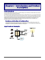
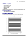
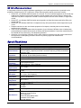
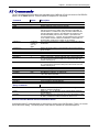
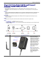
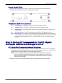
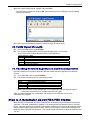
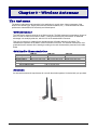
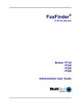
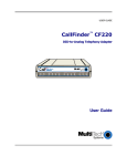
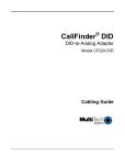
CallFinder® GSM
Cellular Gateway
CF100FX2-G
User Guide
Copyright and Technical Support
User Guide
CallFinder® GSM Cellular Gateway, Model CF100FX2-G
S000420E, Revision E
Copyright © 2009 by Multi-Tech Systems, Inc.
This publication may not be reproduced, in whole or in part, without prior expressed written permission from
Multi-Tech Systems, Inc. All rights reserved.
Multi-Tech Systems, Inc. makes no representation or warranties with respect to the contents hereof and
specifically disclaims any implied warranties of merchantability or fitness for any particular purpose.
Furthermore, Multi-Tech Systems, Inc. reserves the right to revise this publication and to make changes from
time to time in the content hereof without obligation of Multi-Tech Systems, Inc., to notify any person or
organization of such revisions or changes. Check Multi-Tech’s Web site for current versions of our product
documentation.
Record of Revisions
Revision
Date
A
11/03/06
B
04/24/07
C
D
E
10/04/07
04/30/08
07/10/08
05/13/09
Description
Initial release. Version 1.10. Includes the Waste Electrical and Electronic Equipment
Statement.
Add AT commands, update tech support contact list, revise warranty statement, and add
items to Safety Warnings Telecom.
Update tech support list and activation procedures.
Remove CDMA version from manual and update power supply information.
Incoming DTMF tone detection notice.
Added link to website for warranty information.
Trademarks
Registered trademarks of Multi-Tech Systems, Inc. include CallFinder GSM, MultiModem, the Multi-Tech logo, and MultiTech. Windows is a registered trademark of Microsoft Corporation in the United States and other countries. All products or
technologies are the trademarks or registered trademarks of their respective holders.
Technical Support
Country
Europe, Middle East, Africa:
U.S., Canada, all others:
By Email
[email protected]
[email protected]
By Phone
+(44) 118 959 7774
(800) 972-2439 -or- 763-717-5863
World Headquarters
Multi-Tech Systems, Inc.
2205 Woodale Drive
Mounds View, Minnesota 55112
(763) 785-3500 or (800) 328-9717
Fax 763-785-9874
http://www.multitech.com
Warranty
To read the warranty statement for your product, please visit: http://www.multitech.com.
Multi-Tech Systems, Inc.
CallFinder GSM Cellular Gateway
2
Table of Contents
CHAPTER 1 – INTRODUCTION AND PRODUCT DESCRIPTION ......................................................................................... 4 Introduction ...................................................................................................................................................................... 4 Application Example ....................................................................................................................................................... 4 Ship Kit Contents............................................................................................................................................................. 5 Mechanical Mounting ...................................................................................................................................................... 5 Safety Warnings............................................................................................................................................................... 6 Safety Warnings Telecom .......................................................................................................................................... 6 RF Interference Issues ............................................................................................................................................... 7 Specifications .................................................................................................................................................................. 7 AT Commands ................................................................................................................................................................. 8 CHAPTER 2 – GETTING STARTED ............................................................................................................................... 9 Step 1. Obtain a Wireless Account................................................................................................................................. 9 Step 2. Set Voice/Data Switch and Connect Antenna, Serial Cable, & Power .......................................................... 10 Front Panel LEDs ..................................................................................................................................................... 11 CallFinder LED Descriptions..................................................................................................................................... 11 Step 3. Using AT Commands to Verify Signal Strength and Network Registration ................................................. 11 3A. Open the Communications Program .................................................................................................................. 11 3B. Verify Signal Strength ........................................................................................................................................ 13 3C. Checking Network Registration and Roaming Status ........................................................................................ 13 Step 4. A Reminder about FXO/FXS Status ................................................................................................................. 13 CHAPTER 3 – WIRELESS ANTENNAS ........................................................................................................................ 14 The Antenna ................................................................................................................................................................... 14 GSM Antennas ......................................................................................................................................................... 14 GSM Radio Characteristics ...................................................................................................................................... 14 Antenna .................................................................................................................................................................... 14 CHAPTER 4 – WIRELESS CALLFINDER APPLICATION OPTIONS .................................................................................. 15 CHAPTER 5 – TROUBLESHOOTING ............................................................................................................................ 22 General Troubleshooting Tips ...................................................................................................................................... 22 GSM Specific Troubleshooting Tips ............................................................................................................................ 22 APPENDIX A – WASTE ELECTRICAL AND ELECTRONIC EQUIPMENT ............................................................................ 23 Multi-Tech Systems, Inc.
CallFinder GSM Cellular Gateway
3
Chapter 1 – Introduction and Product
Description
Introduction
This User Guide describes the CallFinder ® Cellular Gateway: the CF100FX2-G; a GSM model with connectors
for both the FXS and FXO telephony interfaces.
The CallFinder cellular gateway connects to a PBX trunk line, a PBX extension line, or to a single PSTN (POTS)
line. It routes incoming and outgoing calls through the wireless network. Users can take advantage of the lower
costs that cellular networks offer under certain circumstances (like free calling between cellular phones from the
same provider, and free/reduced costs for weekend and night-time calls initiated on cellular phones). The
CallFinder can also be used to bring phone service to an area where land lines are not available or for
emergency access to the cellular network from a PBX.
Interfaces, Activation, & Configuration
The CF100FX2-G will connect to either an FXS or FXO interface; FXS is the default factory setting. The
CF100FX2-G is activated by inserting a SIM from a cellular provider; no AT commands are required for this.
Configuration is done through Multi-Tech specific AT commands.
Application Example
Multi-Tech Systems, Inc.
CallFinder GSM Cellular Gateway
4
Chapter 1: Introduction and Product Description
Ship Kit Contents
The Wireless CallFinder is shipped with the following:
•
•
•
•
•
•
•
•
One CallFinder Cellular Gateway unit.
An interchangeable power supply.
Four rubber feet for desktop placement.
One printed Quick Start Guide.
One CallFinder Cellular Gateway product CD that contains documentation.
One RJ11 phone cable.
One serial cable.
One antenna.
When unpacking the Wireless CallFinder from its box, check to see that all of the items listed above are present.
Extra Items That You May Need:
• A small needle-nosed pliers for inserting the SIM card.
• A serial-to-USB 2.0 adapter if your command computer lacks a serial port but has a USB 2.0 port.
Mechanical Mounting
If you intend to mount the CF100 on a flat surface, use the dimensions provided on the figure below.
Multi-Tech Systems, Inc.
CallFinder GSM Cellular Gateway
5
Chapter 1: Introduction and Product Description
Safety Warnings
Handling Precautions
All devices must be handled with certain precautions to avoid damage due to the accumulation of static
charge. Although input protection circuitry has been incorporated into the devices to minimize the effect of
this static build up, proper precautions should be taken to avoid exposure to electrostatic discharge during
handling and mounting.
Caution: Maintain a separation distance of at least 20 cm (8 inches) between the
transmitter’s antenna and the body of the user or nearby persons. The modem is not
designed for, nor intended to be, used in applications within 20 cm (8 inches) of the body
of the user.
Safety Recommendations for Rack Installations
• Ensure proper installation in a closed or multi-unit enclosure by following the recommended installation as
defined by the enclosure manufacturer.
• If installing the wireless CallFinder in a closed or multi-unit enclosure, ensure adequate airflow so that the
maximum recommended ambient temperature is not exceeded.
• Do not place the device directly on top of other equipment or place other equipment directly on top of this
device.
• Ensure that the device is properly connected to earth ground via a grounded power cord. If a power strip
is used, ensure that the power strip also provides adequate grounding.
• Ensure that the main supply circuit is capable of handling the load. See the power label on the device for
requirements.
• Maximum ambient temperature is 50 degrees Celsius.
• This device should be installed by qualified personnel.
• Only connect like circuits; e.g., connect SELV (Secondary Extra Low Voltage) circuits to SELV circuits and
TN (Telecommunications Network) circuits to TN circuits.
Safety Warnings Telecom
•
•
•
•
•
•
•
•
•
•
•
•
Never install telephone wiring during a lightning storm.
This product must be disconnected from power source and telephone network interface when servicing.
This product is to be used with UL and cUL listed computers.
Never touch uninsulated telephone wires or terminals unless the telephone line has been disconnected at
the network interface.
Use caution when installing or modifying telephone lines.
Avoid using a telephone (other than a cordless type) during an electrical storm. There may be a remote
risk of electrical shock from lightning.
Do not use the telephone to report a gas leak in the vicinity of the leak.
To reduce the risk of fire, use only 26 AWG or larger telecommunication line cord.
Never install a telephone jack in wet locations unless the jack is specifically designed for wet locations.
Do not connect the FXS port to an outside line (PSTN).
Connect this product only to an indoor antenna.
This product is not intended for use on a cable distribution system.
Multi-Tech Systems, Inc.
CallFinder GSM Cellular Gateway
6
Chapter 1: Introduction and Product Description
RF Interference Issues
It is important to follow any special regulations regarding the use of radio equipment due in particular to the
possibility of radio frequency, RF, interference. Please follow the safety advice given below carefully.
• Switch OFF your Wireless CallFinder when in an aircraft. The use of cellular telephones in an aircraft may
endanger the operation of the aircraft, disrupt the cellular network and is illegal. Failure to observe this
instruction may lead to suspension or denial of cellular telephone services to the offender, or legal action
or both.
• Switch OFF your Wireless CallFinder when around gasoline or diesel-fuel pumps and before filling your
vehicle with fuel.
• Switch OFF your Wireless CallFinder in hospitals and any other place where medical equipment may be
in use.
• Respect restrictions on the use of radio equipment in fuel depots, chemical plants or where blasting
operations are in progress.
• There may be a hazard associated with the operation of your Wireless CallFinder close to inadequately
protected personal medical devices such as hearing aids and pacemakers. Consult the manufacturers of
the medical device to determine if it is adequately protected.
• Operation of your Wireless CallFinder close to other electronic equipment may also cause interference if
the equipment is inadequately protected. Observe any warning signs and manufacturers’
recommendations.
Specifications
Features
CF100FX2-G GSM Modem
GPRS Class 12
Performance
Band, Frequency Dual-band 850/1900 or 900/1800 MHz GSM/GPRS
Half rate (HR), Full rate (FR), Enhanced full rate (EHR), echo cancellation, noise
reduction (option), telephony and Dual Tone Multi Frequency (DTMF) transmission,
Voice Features
emergency calls
Antenna
RF Antenna: 50 ohm SMA (female connector)
Connectors
Standard 3V SIM receptacle
SIM Connector
Interface
9-pin female DB9
Connectors
Power
2.5mm miniature screw
Connectors
Voice Connectors 1 RJ11 FXS port, 1 RJ11 FXO port.
Power
7V to 12 VDC
Requirements
Power
6 watts
Consumption
7 7/16” W x 6 1/8” D x1 1/4” H (16.4cm x 15.6 cm x 3.2 cm)
Physical
1 lb. 3.8 oz (561.33 grams)
Description
Operating
0° to +50° C
Temperature
(+32 to +100 degrees F)
Storage
-40° to +85° C
Temperature
Relative humidity: 25% to 85% non-condensing
Humidity
FCC part 15 class "A",
CE mark,
Certifications
UL 60950
Command
autobaud speeds 115200, 57600, 38400, 9600 (bps); proprietary AT commands
Interface
AT Command Compatible
Desktop or panel mounting
Carrier approved
Miscellaneous
Numerous LEDs display status
Embedded TCP/IP stack
Two year warranty
Multi-Tech Systems, Inc.
CallFinder GSM Cellular Gateway
7
Chapter 1: Introduction and Product Description
AT Commands
The AT commands listed below are those supported by the CallFinder CF100 unit when its VOICE/DATA
switch is in the VOICE position. These are Multi-Tech-specific AT commands.
Command
Values
Description
ATI
ATI1
AT&F
AT>AD=p<cr>
---p = 0 or 1
ATDnA<cr>
AT>AD?<cr>
n is phone
number of
up to 10
digits
--
Returns model number of CallFinder unit.
Returns CallFinder’s software version.
Resets parameter values to factory defaults.
p = 0/1 turns autodial feature off/on. CallFinder must be set to
FXO and connected to a station port (extension) of the PBX. If
autodial feature is enabled and a party at another PBX extension
calls the CallFinder extension, the CallFinder will answer the call
and will immediately direct it to the number, n, specified in the
command ATDnA<cr>. Typically, the auto-dialed number would be
on the cellular network to which the CallFinder is subscribed, but
the destination could be any number (up to 10 digits).
This command specifies the number to which the autodial call will
be directed.
AT>FXS
AT>FXO
AT>HFX=0
AT>HFX=1
--0
1
AT>HFX=2
2
AT>SPK=
AT>MIC=
AT>CID=
AT>MAX=
0-4
0-7
0, 1
0-99
AT>LR=0
AT>LR=1
AT>LR=2
AT>LR=3
Reports the status (off/on) of the autodial function and the stored
phone number.
Sets unit to FXS mode.
Sets unit to FXO mode.
HFX function is off.
Used in voice mode. Causes CallFinder port to open tip and ring
for 4 seconds and causes the PBX port to disconnect when the
cellular side hangs up.
Used in voice mode. Causes CallFinder port to open tip and ring
for 1.2 seconds and causes the PBX port to disconnect when the
cellular side hangs up.
Sets audio output level.
Sets audio input gain.
Turns on/off Caller ID signaling. 0= off; 1= on.
Sets Maximum call time. 0 = feature off;
1-99 = time limit in seconds.
Turns off both line reversal features.
Turns on billing line reversal feature.
Turns on ‘disconnect-on-line-reversal’ feature.
Turns on both line reversal features.
Query Commands
AT>fx?
AT>lr?
AT>CID?
Returns FXS or FXO, depending on the current setting of the
telephony interface parameter.
Returns 0, 1, 2, or 3, depending on the current setting of the line
reversal feature.
Returns CallFinder unit’s status (0= off; 1= on) with regard to Caller
ID, that is, whether the Caller ID function is active or not.
Wireless CallFinder Models and the VOICE/DATA Switch
Configuration with AT commands must be done with the switch in the VOICE position. There is no current
use for the DATA setting. The DATA portion of this switch is available for future development.
Multi-Tech Systems, Inc.
CallFinder GSM Cellular Gateway
8
Chapter 2 – Getting Started
Step 1. Obtain a Wireless Account
Obtain a GSM Network Account
1.
Contact your GSM network agent to obtain an account and/or SIM card. Be sure to specify if you
want a data only, voice only or voice and data account.
2.
Provide the agent with the CallFinder’s model number and IMEI number. Both are located on the
label on the bottom of the product. You will also need to provide information about billing and about
the wireless services/features you need.
3.
After Activation, your agent or wireless provider will give you the following:
∗ a SIM card, and
∗ a phone number.
4.
Install the SIM Card.
Note: The wireless CallFinder requires a SIM card (Subscriber Identity Module) to operate on a GSM
network. The GSM CallFinder will not operate without a SIM.
To install the SIM card:
∗ Use a small screwdriver to remove the screw closest to the outside edge of the modem. Then
swing the loosened SIM slot cover up and over to the left.
∗ Insert the SIM card into the SIM card slot. A small, needle-nosed plier may be useful for this.
The following graphic illustrates the correct SIM card orientation.
∗ Verify that the SIM card fits properly; then replace the cover.
Multi-Tech Systems, Inc.
CallFinder GSM Cellular Gateway
9
Chapter 2: Getting Started
Step 2. Set Voice/Data Switch and Connect
Antenna, Serial Cable, & Power
Voice/Data Switch
Be sure that the VOICE/DATA switch is in VOICE position before connecting the power cord. The
VOICE/DATA switch should always be in the VOICE position. The DATA position is for future potential
products.
Antenna
Connect a suitable antenna to the SMA connector. An antenna is supplied with each unit. See chapter one
of this manual for antenna/RF specifications; see chapter three of this manual for more details about
antennas.
Serial Cable
Connect the DB9-to-DB9 cable between the CallFinder’s RS-232 receptacle and a serial port on your
command computer.
Power
Plug one end of the power cord into the device and the other end onto a live power outlet.
Notes
• The PWR LED. The PWR LED lights after power-up.
• Serial-to-USB 2.0 adapters. If your command computer lacks a serial port, then you will need a serialto-USB2.0 adapter.
Antenna
Power Supply & Connectors
Remove the protective
shipping cover. Attach the
appropriate interchangeable
blade piece to the power
supply module. Connect the
power lead from the power
supply module into the
power connection on the
CallFinder and tighten the
barrel lock. Now, plug the
power supply into your
power source.
Note: Use only the power
supply supplied with the unit.
Use of any other power
supply voids the warranty
and can damage the
modem.
Multi-Tech Systems, Inc.
CallFinder GSM Cellular Gateway
10
Chapter 2: Getting Started
Front Panel LEDs
Once the power is connected, the LEDs on the front panel will present information about the
CallFinder’s wireless modem functions, including signal strength.
CallFinder LED Descriptions
RI
RING INCOMING - Indicates an incoming ring from the wireless module.
CD
CONNECT DATA – This LED is not used as it is for future potential products.
LS
LINK STATUS - This LED blinks when there is network activity between the carrier and the
cellular module.
OH
OFF HOOK indicator - This LED lights whenever the FXO or FXS interface is active.
Signal Signal Strength - Three LEDs. If at least one LED (the left-most LED) is lit, there is enough
signal to maintain the wireless connection with Low signal strength. If the left two LEDs are
lit, a Medium signal strength is present. If all three LEDs are lit, a High signal strength is
present.
Step 3. Using AT Commands to Verify Signal
Strength and Network Registration
3A. Open the Communications Program
A1. Connect the command cable between the CallFinder and the command computer. The CallFinder
is shipped with a standard DB9 serial cable, male at one end (for attachment to the CallFinder) and
female at the other end (for attachment to the command computer).
NOTE: If your command computer has no serial ports but has only USB ports instead, you
must obtain a USB2.0-to-Serial adapter (“dongle”) for use between the serial cable
and your computer’s USB port. This USB2.0-to-Serial adapter must have a male end
to attach to the DB9 cable.
A2. At the command PC, open the HyperTerminal (or equivalent) communications program.
Multi-Tech Systems, Inc.
CallFinder GSM Cellular Gateway
11
Chapter 2: Getting Started
A3. Establish a named HyperTerminal ‘connection’ to the CallFinder.
A4. Select the command computer’s available COM port that is physically connected to the CallFinder.
Click OK.
A5. At the “COMx Properties” screen, set the connection parameters to these values:
Bits per second = 115200
Data bits: = 8
Parity:
= none
Stop bits: = 1
Flow control= Hardware
Click Apply and click OK. Click OK again when the “COMx Properties” screen returns.
Multi-Tech Systems, Inc.
CallFinder GSM Cellular Gateway
12
Chapter 2: Getting Started
A6. At the HyperTerminal prompt, type AT and press Enter.
The CallFinder will return the response OK, thus confirming that the CallFinder is communicating
with the command PC.
At this point, the communications program is set up for steps 3B and 3C below.
3B. Verify Signal Strength
B1.
In the command window, type AT+CSQ
B2.
The modem responds with the received signal strength (rssi) in numeric form.
The meaning of the number returned is shown in the table below.
Signal Strength – RSSI
20 - 31
High signal (three LEDs lit)
10-19
Medium signal (two LEDs lit)
4-9
Low signal (one LED lit; CallFinder can operate with this level of signal)
0-3
Insufficient signal (no LEDs lit)
99
No signal (no LEDs lit)
3C. Checking Network Registration and Roaming Status
Use this command to verify that the wireless CallFinder modem has been registered on a wireless
network.
C1.
C2.
In the command window, type AT+CREG?
The modem will respond in one of the following ways:
Value
+CREG: 0,0
+CREG: 0,1
+CREG: 0,5
Network Registration Verification
Network Registration Status
The modem is not registered on any network
The modem is registered on the home network
The modem is registered on a network and it is roaming
Note: If the CallFinder modem indicates that it is not registered, verify the signal strength to
determine if the problem is the strength of the received signal.
When you have completed your configuration and checking of the CallFinder, exit from the
communications program.
Step 4. A Reminder about FXO/FXS Status
So far we have not mentioned the FXS or FXO interface connectors on the back panel of the Wireless
CallFinder. This issue is addressed in Chapter 4. Be aware that the CallFinders are set to FXS at the
factory. Note also that in order to use the FXO interface connector you must re-set the interface using a
communications program (like HyperTerminal). It does not work merely to connect the CallFinder to a
telephony device using the FXO connector. The internal setting must be set to match the connector that
you use.
Multi-Tech Systems, Inc.
CallFinder GSM Cellular Gateway
13
Chapter 3 – Wireless Antennas
The Antenna
The antenna sub-system and integration in the application is a major issue. Many parameters of the
antenna are variable (type, length, performances, thermal resistance, etc.). These elements can affect
performance characteristics like sensitivity and emitted power.
GSM Antennas
The CallFinder’s antenna connector is an SMA connector. The SMA connector incorporates a 'Screw-on’
action in order to make the connection easier. It also gives excellent RF performance. An additional
advantage is its small physical size, which is 50% of the standard MCX connector.
This type of connector is suitable for the standard ranges of flexible and semi-rigid cables. The
characteristic impedance of the MMCX coaxial connector is 50 ohms. The antenna manufacturer must
guarantee that the antenna will be working according to the radio characteristics presented in the table
below.
GSM Radio Characteristics
GSM 850
GSM 1800
Frequency RX
869 to 894 MHz
1805 to 1880 MHz
Frequency TX
824 to 849 MHz
1710 to 1785 MHz
RF Power Stand
2W at 12.5% duty cycle
1W at 12.5% duty cycle
Impedance
50 ohms
VSWR
<2
Typical Radiated Gain
0 dBi on azimuth plane
GSM 1900
1930 to 1990 MHz
1850 to 1910 MHz
1W at 12.5% duty cycle
Antenna
An antenna that meets the requirements for use with the wireless product is included with your purchase.
Multi-Tech Systems, Inc.
CallFinder GSM Cellular Gateway
14
Chapter 4 – Wireless CallFinder
Application Options
Prerequisites: A. You must have a valid and activated SIM chip from your wireless service provider
B. Be sure the VOICE/DATA switch is in the VOICE position.
C. You will need a serial-to-USB2.0 adapter if your command computer lacks a serial port (see
step 2).
1. There are four common setups for the CF100FX2-G unit, as shown in the table below. Identify the situation in
which you will use the Wireless CallFinder.
CallFinder connects to...
Situation 1
an analog telephone
Situation 2
Situation 3
a PBX trunk port (also
referred to as a CO
port)
a PBX station port
Situation 4
a telco POTS line
Interface
FXS
FXS
FXO
FXO
Purpose
Cellular service to kiosk or remote location lacking
land lines.
Cellular access through PBX trunk port (to enjoy
free/reduced cellular rates), as well as emergency
phone service in case of PSTN failure.
Cellular access through PBX station port (to enjoy
free/reduced cellular rates), as well as emergency
phone service in case of PSTN failure.
Free or reduced-rate access to a local PSTN from
distant cell phones.
The CF100FX2-G is set to FXS by default. Because FXS is the default, if your application fits Situation 1 or
Situation 2 (requiring the FXS interface), you can skip to step 10 and, from there, proceed to the setup
description for Situation 1 or 2. If your application fits situations 3 or 4, proceed to step 2.
2. Connect the command cable between the CallFinder and the command computer. The CallFinder is shipped
with a standard DB9 serial cable, male at one end (for attachment to the CallFinder) and female at the other
end (for attachment to the command computer).
NOTE: If your command computer has no serial ports but has only USB ports instead, you must
obtain a USB2.0-to-Serial adapter (“dongle”) for use between the serial cable and your
computer’s USB port. This USB2.0-to-Serial adapter must have a male end to attach to the
DB9 cable.
3. At the command PC, open the HyperTerminal (or equivalent) communications program.
4. Establish a named HyperTerminal ‘connection’ to the CallFinder.
Multi-Tech Systems, Inc.
CallFinder GSM Cellular Gateway
15
Chapter 4: Wireless CallFinder Application Options
5. Select one of the command computer’s available COM ports for the connection. Click OK.
6. At the “COMx Properties” screen, set the connection parameters to these values:
Bits per second = 115200
Data bits:
=8
Parity:
= none
Stop bits:
=1
Flow control
= Hardware
Click Apply and click OK. Click OK again when the “COMx Properties” screen returns.
7. At the HyperTerminal prompt, type AT and press Enter.
The CallFinder will return the response OK, thus confirming that the CallFinder is communicating with the
command PC.
Multi-Tech Systems, Inc.
CallFinder GSM Cellular Gateway
16
Chapter 4: Wireless CallFinder Application Options
8. To determine whether the CF100 is set as FXS or FXO, type at>fx? .
The CallFinder will return either “FXS” or “FXO.”
9. To set the interface as needed for your system, type the appropriate command:
AT>FXS and then press Return.
AT>FXO and then press Return.
10. Connect the RJ-11 cable to the appropriate receptacle on the CallFinder (FXS or FXO).
Connect the other end of the RJ-11 cable to the telephony device appropriate for your situation (analog
phone, PBX CO/line port, PBX station port, or telco POTS line).
Important note about DTMF tones
When the GSM network sends DTMF digits to the CallFinder, they are "in-band" as part of the compressed
voice stream. This audio compression may distort the DTMF digits causing them to be "out of spec". Because of
this potential distortion, we cannot guarantee that the attached PBX will properly detect incoming DTMF digits.
Connection Situation #1: CF100 to Analog Phone
Cellular Network
FXS
CF100
Wireless
CallFinder
2nd Party Phone
Analog Phone
1. Plug an analog phone into the FXS port of the CF100 Wireless CallFinder.
2. Make a call to a 2nd Party with the analog phone (dial as you would from any cell phone).
3. If a connection is made, the CF100 CallFinder has been configured properly.
If a connection is not made, see the “Troubleshooting” tips in Chapter 5 of this manual.
Multi-Tech Systems, Inc.
CallFinder GSM Cellular Gateway
17
Chapter 4: Wireless CallFinder Application Options
Connection Situation #2: CF100 to PBX’s CO Port
Cellular Network
1
PBX
1
2
2nd Party
Phone
3
FXS
CF100
Wireless
CallFinder
4
2
Analog
CO/Line
Ports
Analog
Station
Ports
(POT 1-4)
Ethernet Port
3
4
Ext 203
Analog
Phone
Ext 3009
IP Phone
1. Setting Directionality. In the PBX software, set the “Direction” parameter to Both Directions to allow both
inbound and outbound calling through the CallFinder.
2. Outgoing Calls. Set up the PBX with an access code for outgoing calls. “9” or “8” are commonly used as
access codes for special connections from a PBX.
3. Incoming Calls. For incoming calls, you must set additional parameters in the PBX software. Incoming CO
calls should be routed to ring a group of phones (in our example, we have a group of two members: extension
203 is an ordinary station port serving a POTS phone; 3009 is an extension connected through the Ethernet
Port and terminating in an IP phone). Alternatively, one could also route these incoming calls to an autoattendant.
4. Resulting Performance – The Inbound Calling Pool. By setting up the PBX as shown above, multiple
extensions will ring when a call comes into the PBX through the CF100 CallFinder. The first person to answer
completes the call, the ringing will cease, and the call cannot be joined by subsequent members of the huntgroup who might try to answer the call.
Multi-Tech Systems, Inc.
CallFinder GSM Cellular Gateway
18
Chapter 4: Wireless CallFinder Application Options
Connection Situation #3:
CF100 to Analog Station Port on PBX
Caution: When connecting a CF100 CallFinder to an analog station port and allowing incoming calls
through that CallFinder, the PBX must be configured to prevent the incoming caller from using
the CallFinder’s secondary dial tone to make calls to a third party. Such ‘call-through’ activity
could be expensive to the PBX owner. The secondary dial tone is intended to allow the outside
party to reach any extension on the PBX. However, without limitations on dialing at the
secondary dial tone, an unscrupulous caller could make toll calls (perhaps very expensive
calls) that would be charged to the PBX.
1. Set CallFinder’s Interface to FXO. Use HyperTerminal (or other communications program) to check the
current Interface setting, to change the Interface to FXO if necessary, and to confirm that change.
Multi-Tech Systems, Inc.
CallFinder GSM Cellular Gateway
19
Chapter 4: Wireless CallFinder Application Options
2. Connect Cables. Identify the PBX station port to be used and connect an RJ11-to-RJ11 cable between the
PBX station port and the CF100 FXO port.
Cellular Network
1
PBX
2
3
4
CF100
Wireless
CallFinder
FXO
1
2
Analog
CO/Line
Ports
Analog
Station
Ports
(1-4)
Ethernet Port
3
2nd Party Phone
4
Ext 203
Analog Phone
Ext 3009
IP Phone
3. Configuring PBX software for Outbound Calling through CallFinder. Any user of the PBX (whether that user
is on an analog station port or is connected via Ethernet to an IP phone) can call the analog station port to
which the CF100 is connected (“ext 204” in our example) and get a secondary dial tone from the CallFinder.
This secondary dial tone gives PBX users access to the wireless network. They simply dial 204 and the
CallFinder produces the secondary dial tone.
To set up the PBX software for this equipment configuration, follow the sub-steps below.
3A. In the PBX software, select the extension (station port) to which the CF100 is attached.
3B. In the PBX software, select the ‘User’ identifier of the CF100 (in our example, it’s “Ext204”).
3C. In the PBX software, disable voicemail for the extension used by the CallFinder.
4. Configuring the PBX software for Inbound Calling through CallFinder. Restrictions must be placed on the
inbound callers’ use of the secondary dial tone given to them by the CF100. The restrictions must prevent
the inbound caller from making toll calls billable to the PBX.
The most straightforward way to prevent such piracy of phone services is to block the incoming caller from
using, as initial dialed digits, the outbound access digits that would be needed to re-dial outward (for
example, 8, 9, and 1).
Multi-Tech Systems, Inc.
CallFinder GSM Cellular Gateway
20
Chapter 4: Wireless CallFinder Application Options
Connection Situation #4: CF100 to Telco POTS Line
National
Cellular Network
Local
PSTN
FXO
CF100
Wireless
CallFinder
POTS
Line
1. Set CallFinder’s Interface to FXO. Use HyperTerminal (or other communications program) to check the
current Interface setting, to change the Interface to FXO if necessary, and to confirm that change.
2. Connect Cables. Connect an RJ11-to-RJ11 cable between the telco POTS line and the CF100 FXO port.
3. Purpose. This setup allows cell phone users to have toll-free access to land-line phone numbers in the local
PSTN where the CallFinder is located.
Multi-Tech Systems, Inc.
CallFinder GSM Cellular Gateway
21
Chapter 5 – Troubleshooting
General Troubleshooting Tips
1. Be sure that the RJ11 cable is plugged into the CallFinder telephony connector that is appropriate for your
application (either the FXS or the FXO interface).
2. To check which interface type your CallFinder is set for internally, use a terminal program (like
HyperTerminal) accessed at your command computer (connected from serial port on computer to RS-232
connector on CallFinder). The terminal program should be set to 115200 bps, 8N1, and Hardware flowcontrol type. The command used to check the CallFinder’s current interface type is AT>FX?. The CallFinder
will return either “FXS” or “FXO” in response.
3. Check the VOICE/DATA switch on the back of the CallFinder. It should be in the VOICE position during
operation. The switch on the GSM CallFinder never needs to be in the DATA position. Be sure that the
switch is definitely in the VOICE position during operation.
4. Check the signal strength LEDs. At least one LED should be illuminated. If not, your Wireless CallFinder
does not have enough signal strength to operate properly.
GSM Specific Troubleshooting Tips
1. Check the orientation of the SIM. It is possible to install the SIM backwards and/or upside down.
Note that your Wireless CallFinder will produce dial tone even if there is no SIM installed.
2. Try calling the telephone number assigned to the SIM. It is possible that your service is not ready or that
there is a problem with your subscription.
Multi-Tech Systems, Inc.
CallFinder GSM Cellular Gateway
22
Appendix A – Waste Electrical and
Electronic Equipment
July, 2005
Waste Electrical and Electronic Equipment (WEEE)
The WEEE directive places an obligation on EU-based manufacturers, distributors, retailers and importers to take-back
electronics products at the end of their useful life. A sister Directive, ROHS (Restriction of Hazardous Substances)
complements the WEEE Directive by banning the presence of specific hazardous substances in the products at the design
phase. The WEEE Directive covers all Multi-Tech products imported into the EU as of August 13, 2005. EU-based
manufacturers, distributors, retailers and importers are obliged to finance the costs of recovery from municipal collection
points, reuse, and recycling of specified percentages per the WEEE requirements.
Instructions for Disposal of WEEE by Users in the European Union
The symbol shown below is on the product or on its packaging, which indicates that this product must not be disposed of
with other waste. Instead, it is the user’s responsibility to dispose of their waste equipment by handing it over to a designated
collection point for the recycling of waste electrical and electronic equipment. The separate collection and recycling of your
waste equipment at the time of disposal will help to conserve natural resources and ensure that it is recycled in a manner
that protects human health and the environment. For more information about where you can drop off your waste equipment
for recycling, please contact your local city office, your household waste disposal service or where you purchased the
product.
Multi-Tech Systems, Inc.
CallFinder GSM Cellular Gateway
23