1
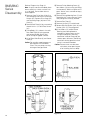
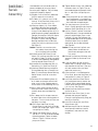
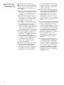
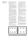
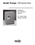
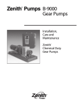
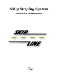
Zenith Pumps
®
B-Series
Gear Pumps
Installation,
Care and
Maintenance
Zenith
Chemical Duty
Gear Pumps
®
Thoroughly read and understand this entire manual
before installation and operation of pump.
®
Zenith
®
In 1926, Zenith was approached by the
synthetic fiber industry to design a
pump to provide a precise, pulseless,
repeatable flow and assure better quality
control. The options then were the same
as those in the chemical process industry
today — diaphragm, lobe, coarse gear,
piston, plunger and screw pumps. Each
had problems with pulsation, flow inaccuracies, multiple seal areas and slippage,
which required constant calibration, high
maintenance and extended downtimes.
Zenith met the challenge and
designed a rotary external gear pump
of unique precision and simplicity. Man-
ufacturing techniques were developed to
hold tolerances to ±.00005", minimizing
internal clearance to assure accurate and
precise metering. The pump’s simplistic
design of only three moving parts–two
metering gears and a drive shaft–provided long life and easy maintenance.
For years since, chemical engineers
have relied on Zenith to provide precision
fluid handling solutions for their most
difficult pumping applications. Zenith
gear pumps can be found wherever
precise, pulseless, repeatable metering
of fluids is required.
High Accuracy
Stable, repeatable flows are assured
even under varying conditions of
temperature, viscosity and pressure.
High Volumetric Efficiency
Maximum efficiency is achieved
with optimum operating clearances.
®
Benefits
Minimum Pulsation
Unique design offers virtually pulseless
flow without valves or flexible elements
to hinder performance.
Precision Construction
Ground and lapped components and
built-in dowels allow for close control
of operating clearances.
Specifications
®
®
Corrosion Resistance
400 series stainless steel provides good
bearing qualities and the necessary
corrosion resistance for most standard
chemical processes.
Maximum Life
Only three moving parts; components
are through hardened to HRc 54 or better.
Pump Type: Rotary external spur gear, single stream.
Rotation: See pump drawing.
Operating Speed: 3-180 rpm depending upon application conditions and fluid
viscosity.
Temperature: To 300° F (150° C). Heat jacket required for above ambient
temperatures.
2
Design
The B-Series pumps are constructed
from cutlery grade 420 and 440C stainless steel. The pumps consist of two or
three gears rotating in mesh within a
closely fitted housing that is comprised
of three plates. The center or gear plate
fits closely around the outside diameter
of the metering gears. The front and rear
plates sandwich the gear plate and
restrict axial movement of the gears. In
the BPB, BMB, BLB, and BXB series, the
gear set is comprised of a driving and a
driven gear. The BMC series is comprised of a driving gear and two driven
gears. In all series, the driving gear is
keyed to the drive shaft while the driven
gears ride on stationary arbors.
The B-Series pumps have two seal
designs: a mechanical face seal and a
lip seal (the BMB/BMC has only a lip
seal). The standard seal is a single or
double lip seal while the mechanical
face seal is available as an option. The
mechanical face seal design consists of
a rotating universal seal coupling that
acts as a coupling between the inner and
outer drive shafts and, at the same time,
seals against a fixed seal plate or anchor
washer. The mechanical face seal is
dependent upon sufficient inlet pressure
(usually 25-50 psi) to force the inner
rotating coupling against the outer stationary anchor. This design is common
in abrasive fluid applications.
Since the metal seal requires sufficient
inlet or working pressure to be effective,
a spring-loaded lip seal design is usually
recommended. Pumps with lip seals
normally will only require a flooded inlet.
The BPB pumps use a lip seal with an
“O” ring; the BMB/BMC pumps use a
lip seal alone; and the BLB and BXB
pumps use two lip seals. The Teflon
lip seal with stainless steel spring is
chemically inert and is most commonly
used for general-purpose metering in a
variety of applications.
All B-Series pumps (with the exception of the BXB) come equipped with an
outer drive gear and drive strap. The
BXB Series is direct drive. The outer
drive gear is meshed with a pinion gear
mounted on the output shaft of a motor or
gear box. The drive strap is incorporated
into the design to act as the weak element
in the pump. Should something go
wrong in the process, such as line
blockage, the increased back pressure
will increase the amount of torque
required to turn the pump. The drive
strap is designed with a critical breaking
torque that will allow it to fail before any
excess stress is exerted on the internal
pump parts. This protects the precision
manufactured inner workings of the
metering pump.
3
Operation
In the trunnion-ported BPB, BMB and
BMC pumps, fluid enters the pump at
the outer drive gear side of the pump. A
passage has been drilled from the inlet
port up through the front plate into the
center plate gear pocket. Fluid flows into
the gear pocket and fills the gear tooth
volumes. As the gears rotate, the fluid is
transported around the outer diameter of
the gear pocket to the discharge side.
As the gears mesh together, the fluid is
displaced back down a passage drilled
into the rear plate and out the discharge
port at the rear side of the pump.
In rear-ported BPB, BLB and BXB
pumps, fluid enters the pump through a
port drilled into the rear side plate (the
side opposite the outer drive gear/shaft).
The fluid again fills the exposed gear
tooth volumes and is transported around
the outer diameter of the gear pocket.
As the gears mesh, the fluid is displaced
out through the discharge port that is
drilled alongside the inlet port in the rear
plate.
Since Zenith pumps are not selfpriming, a flooded suction is usually the
minimum inlet pressure required. However, when high-viscosity fluids are
used, more time is required to fill the
tooth volumes. As a result, the inlet
pressure must be increased or the gears
must rotate at a slower speed to ensure
complete volume filling and to prevent
cavitation.
®
®
Zenith pumps rely on the metered
fluid for lubrication of internal bearing
areas. The pump should never be
allowed to run dry or be allowed to run
with non-lubricating fluids such as water.
Because of close clearances in the
bearing areas, lack of sufficient lubrication
can cause pump seizure and possibly
catastrophic failure.
Under extreme conditions, slip may
occur across the face of the gears from
in between the high-pressure side to the
low-pressure side. Pump efficiency
depends on four factors: fluid viscosity,
pump speed, differential pressure and
gear clearances. Under reasonably
stable operating conditions, slip is
repeatable and predictable, and
pump operation can be adjusted to
compensate.
The Zenith B-Series pumps are
designed for low-temperature operation.
As such, the maximum operating temperature should not exceed 300° F.
When operating at temperatures above
ambient, heat jackets should be used,
and pumps should be heated slowly
and uniformly.
The 400-Series stainless steels used
in the construction of the B-Series
pumps provide sufficient corrosion
resistance for most standard chemical
processes. The material hardness will
provide a high degree of wear resistance
as well. However, processes involving
corrosive or abrasive fluids should
always be approved by Zenith .
®
®
4
Installation
Pumps should be carefully unpacked
and checked to make sure that the shipment is complete. If any items are missing or damaged, the freight carrier and
Zenith should be notified immediately.
The following is a general installation
procedure. For special applications,
considerations, or simply to ask for
advice, please contact our Applications
Engineering Group.
It is not recommended to flush
downstream process equipment utilizing
Zenith precision metering pumps. Most
fluids used as flushing agents, such as
solvents and water, have a low viscosity
and have poor lubricating qualities.
Catastrophic failure may occur
under certain operating conditions. If it
is necessary to flush the system, the
following suggestions are recommended
to prevent premature pump failure:
®
®
1) If possible, flush the system using a
lubricating fluid.
2) Minimize the differential pressure
across the pump ports to 25 psi.
3) Reduce the pump speed to an
acceptable level (approximately 10
rpm).
4) Flush the pump for the shortest
allowable time, yielding effective
cleansing of the system, and no
longer than necessary.
5) It is recommended to use a bypass
around the pump as illustrated in
Figure A. This will allow for high velocity
flushing of the system while minimizing
risk to the metering pump. During the
flush cycle, fluid will pass through and
around the pump. This will allow the
system to be flushed quickly and
effectively.
Figure A
Pump
To prepare the pump for use:
1) Always flush out the plumbing system
before connecting the pump.
2) Filters should be installed prior to the
pump inlet and should filter ideally to
half the pump gear clearances.
3) Turn pumps by hand before running.
Pumps should turn freely.
4) Pivot mount pumps should be mounted
in the L-5677 mounting saddle, and
the trunnions should be loosely
tightened to support but not restrict
movement of the pump. Fixed-mount
pumps should be installed on an
L-shaped saddle, and mounting
screws securely tightened.
5) Make certain that bearing grease has
been applied between the hub and
Outer Drive Gear. If necessary, apply
a suitable lubricant to the grease fitting
located on the pump. Rotate the Outer
Drive Gear, by hand, to ensure that a
layer of grease is evenly spread
between the hub and outer drive gear
bearing area. Pumps without a grease
fitting do not require lubrication.
Note: Lubrication applied to a grease
fitting will not lubricate internal bearings
or come in contact with the pumped fluid.
6) Carefully mesh the outer drive gear
with the drive pinion gear. A backlash
of .005" is recommended. Trunnions
can then be securely tightened.
7) Make sure the pump is primed before
starting. Be sure to apply positive inlet
pressure when metering high-viscosity
fluids. Pumps with universal face seals
require approximately 25-50 psi inlet
pressure to seat the seal.
8) Start the pump slowly and, if possible,
operate with a lubricating fluid.
9) When satisfactory operation is
achieved, the pump and system may
be gradually brought up to normal
operating conditions.
10) If, at any time during operation, the
pump does not appear to be running
smoothly, stop the pump immediately
to avoid serious internal damage.
Bypass
Valve
5
Cleaning,
Inspection
and Repair
Lapping
Or Blocking
®
Zenith metering pumps are made for
exacting duty. All parts are machined to
extreme accuracy; critical dimensions
are held between one and two tenthousandths of an inch (.0001"/.0002").
Accurate performance is dependent
upon proper handling. Please treat them
with care, and if it’s at all possible, set
aside a separate clean area for pump
maintenance.
It is recommended that pump users
institute a program of dimensional inspection of critical parts in order to keep
maintenance and operating costs at a
minimum. By noting the performance of
a pump immediately before removing it
from service and correlating the performance to measured component wear,
the user can establish the maximum
wear limits for the pump’s critical components. Further, the service life of the
pump can be predicted and downtime
scheduled accordingly.
As with any other Zenith pump,
B-Series pumps may be returned to
Zenith for complete rehabilitation. This
procedure may be desirable if only a
few pumps are involved. If a large
number of pumps are to be maintained
at the user’s plant, it may be worthwhile
to have key personnel attend a maintenance seminar at Zenith to learn the
manufacturing, gauging, and assembly
techniques involved in producing the
B-Series pump. In addition, Zenith also
offers a contract service program. Please
contact Zenith for further information on
these items.
Remember: Zenith pumps are precision instruments. You can’t keep them
too clean. The slightest bit of debris may
cause damage.
Place two layers of 400-Grit Emery Cloth
on a lapping block or plate–a granite flat
is suitable. Apply light pressure to the
component and turn it in a “Figure 8”
pattern (as shown in Figure 1) approximately 10 times until a smooth finish
appears. Components that are commonly
lapped are the sides of metering gears
and the inside faces of front, rear and
center plates. The components are now
ready to be cleaned. An ultrasonic
cleaner with a safe industrial solvent (Nu
solution) is preferred, but you may also
use a large container filled with about
four inches of solution.
Caution: Never drop the components
into a tank or container; place them gently
onto the bottom to avoid damage.
Always use clean, lint-free rags and
compressed air to clean components.
Paper towels are not acceptable; they
may leave small pieces of paper and
dust on the components. Use chemical
brushes to clean between gear teeth,
bores and reliefs. Tooth brushes are not
acceptable. After all components are
“hospital clean,” the pump is ready for
assembly.
New parts should be deburred and
cleaned using the above procedures.
®
®
®
®
®
®
*
*
*
*
*
*
Figure 1
6
Note: Part should be rotated by quarter turns as it moves
through a "Figure 8" pattern.
BPB Series
Disassembly
Refer to Diagram 1 on Page 10 (general
reference only).
Note: As parts are disassembled, place
them carefully on a clean surface such
as a soft cloth. Do not allow them to
knock together.
1) Remove Outer Drive Gear (18) by first
removing Drive Strap Screws (28) and
Drive Strap (20). Slide Yoke Retainer
(19) out of slot in Hub (12).
2) Pull Outer Drive Shaft (11) out of
Hub (12).
3a) LIP SEAL DESIGN. Place pump in a
soft-jawed vise with the Hub (12)
facing upward. Never clamp on
lapped surfaces. Remove three #1024 Hub Screws (27) and Hub (12).
Note: We strongly advise removing
the Lip Seal (14) from the Hub (12)
and discarding it.
3b) METAL SEAL DESIGN. Place pump
in a soft-jawed vise with the Hub (12)
facing upward. Never clamp on
lapped surfaces. Upon removal of
the three #10-24 Hub Screws (27),
the Hub (12), Coupling Housing (13),
Anchor Washer (15) and Universal
Seal Coupling (14) are all easily
removed. Remove and carefully
store the Compression Spring (16).
4) Turn the pump over and clamp the
vise onto the Front Side Plate (1).
Remove two of the diagonally opposed
#12-24 Binder Screws (21). Loosen
the other two screws but leave them
engaged by two or three threads.
5) Separate the Front Side Plate (1) and
Rear Side Plate (3) by gently tapping
the slightly engaged Binder Screws
(21) with a plastic hammer.
6) Lift off the Rear Side Plate (3), Center
Plate (2) and Spacer (9).
Caution: Do not allow the metering gears
to be lifted out with the Center Plate (2).
They may drop, causing damage to the
gear teeth. On Metal Seal Design
pumps, be careful to retain Ball (29).
7) Remove Driving Metering Gear Assembly (6) by gently turning and lifting.
Repeat for Driven Metering Gear (7).
Never use pliers to lift gears. Never
use a screwdriver to pry gear upward.
If there is a film of oil or other tenacious fluid between the gear and the
side plate, it helps to immerse the
parts in solvent. On Metal Seal Design
pumps, Driving Metering Gear (6) and
Drive Shaft (4) are not a press fit
assembly.
8) Remove Port Seal Screws (23 & 25)
and Gaskets (22 & 24). Repeat for
Shaft Seal Screw (31) and Gasket (30).
9) If the Arbor (5) is to be replaced or
thoroughly checked, press out by
using an arbor tool, pressing towards
the inside of the pump (the shortest
press direction). Repeat for Dowels (10).
7
BPB Series
Assembly
Considerable care should be taken to
prevent wedging or jamming. Never
force the parts together. They will drop
into place if properly aligned.
1) Provide a can of clean oil, preferably
SAE-50 motor oil or mineral oil.
2) Press Arbor (5) and Dowels (10) into
Rear Side Plate (3) using the Driven
Metering Gear (7) as a guide for
press-ing the arbor upright and perpendicular to the plate. See Figure 2.
3) Install Port Seal Screws (23 & 25) in
both plates with new Gaskets (22 &
24). Repeat for Shaft Seal Screw (31)
and Gasket (30).
4) Fix the Rear Side Plate (3) in a bench
vise inside face up.
5) Lubricate the drive shaft bearing hole
and arbor with a few drops of oil. See
Figure 3.
6a) LIP SEAL DESIGN. Place Driving
Metering Gear Assembly onto plate.
Place the shaft into bearing hole,
rotating several times to insure free
rotation.
6b) METAL SEAL DESIGN. Place Ball
(29) into depression on shaft seal
screw. Assemble loose-fit Driving
Metering Gear (6), Drive Shaft (4)
and Key (8). Place stub end of drive
shaft into bearing hole and rotate
several times to insure free rotation.
7) Position Driven Metering Gear (7)
over the Arbor (5), rotating several
times to insure free rotation.
8) With a thin film of oil on your fingertips,
lubricate the gear pockets of the
Center Plate (2).
9) Carefully lower Center Plate (2) over
gears.
10) Lower Spacer (9) over Dowel (10).
11) Place a drop of oil into each port in
Center Plate (2) (i.e. either side of
meshing gear teeth) and turn Drive
Shaft (4) several times to insure free
rotation. See Figure 3.
12) Carefully lower the Front Side Plate
(1) over the Dowel (10) and Drive
Shaft (4).
13) Flip pump over in the vise, clamp to
Front Side Plate (1), and insert
Binder Screws (21) until finger tight.
Check for free rotation.
14) Tighten binder screws to 60 lbs.-in.,
50% of the recommended tightening
torque. Follow the order shown in
Figure 4 depending on whether the
pump has 4 or 6 binder screws. Be
sure the pump turns freely.
8
15) Tighten binder screws to the recommended tightening torque of 120
lbs.-in.; follow the order shown in
Figure 4.
Note: If the pump will not turn freely after
each component is installed, then
the last piece installed needs additional attention or replacement.
16) Flip pump over and fix it in a vise. Set
leading chamfer of Lip Seal (14) into
Hub (12) opening. For Metal Seal
Design pumps, place Compression
Spring (16) into hole on top of Drive
Shaft (4).
17) LIP SEAL DESIGN only. Use of the
Zenith Lip Seal Installation Guide is
recommended to prevent lip seal
damage. [P/N 14-00131-0001-1
(Items A,B & C)].Set guide (B) down
over Lip Seal (14) and against the
Hub (12) in order to compress the
seal O.D. and ease its entry into the
hub. See Figure 5.
18a) LIP SEAL DESIGN. Holding the Lip
Seal Guide (B) against the Hub
(12), press the Lip Seal Inserter (C)
down firmly, but gently, until Lip
Seal (14) is seated against the
bottom of the hole. Be careful not
to crush the seal. See Figure 5.
18b) METAL SEAL DESIGN. Place the Universal Seal Coupling (14) over the
drive shaft and slide the Coupling
Housing (13) over the coupling. The
Anchor Washer (15) is then inserted
into the coupling housing right on
top of the coupling itself. The two
ears on the anchor washer fit into
grooves in the housing. See
Diagram 1 Inset.
19) LIP SEAL DESIGN only. Place “O” Ring
(32) over the Drive Shaft (4) and
using the Bullnose (A) on end of
Drive Shaft (4), carefully lower hub
and seal assembly down over Drive
Shaft (4). See Figure 6.
20a) LIP SEAL DESIGN. Remove Bull-nose
Installation Tool and rotate Hub (12)
until grease fitting is facing in the
desired orientation.
20b) METAL SEAL DESIGN. Place the Hub
(12) on top of the Coupling Housing
(13) and orient the Grease Fitting
(26) as desired.
21) Insert Hub Screws (27) and tighten
to first 32 lbs.-in. in a circular rotation,
then complete tightening to recommended torque of 64 lbs.-in.
®
BPB Series
Assembly
(continued)
22) Place Outer Drive Shaft (11) into Hub
(12) (when applicable), and rotate
until Drive Shaft (4) and Outer Drive
Shaft (11) mate.
23) Place Outer Drive Gear (18) over
Hub (12), insert Yoke Retainers (19)
into appropriate grooves followed by
Drive Strap (20) and tighten down
with Drive Strap Screws (28).
24) Pour oil into inlet port to lubricate
internal components, then rotate
pump to check for free rotation.
25) Apply standard gun grease to
Grease Fitting (26). Conoco Super
Lube M EP Grease or equivalent is
recommended.
Figure 2
Figure 3
Figure 4
Figure 5
Figure 6
9
BPB Series
Diagram 1
BMB/BMC Series
Diagram 2
10
BLB Series
Diagram 3
BXB Series
Diagram 4
11
BMB/BMC
Series
Disassembly
Refer to Diagram 2 on Page 10.
Note: As parts are disassembled, place
them carefully on a clean surface such
as a soft cloth. Do not allow them to
knock together.
1) Remove Outer Drive Gear (2) by first
unscrewing the two #10-24 Drive Strap
Screws (32). Remove Drive Strap (31)
and Retaining Rings (30) from Drive
Shaft (8).
2) Remove Seal Plate (16) by unscrewing
three #10-24 x 1/2" Seal Plate Screws
(20).
3) Clamp Body (1) in a bench vise with
Rear Side Plate (3) facing upward
and remove Binder Screws (28).
Never clamp on lapped surfaces.
4) Lift off Rear Side Plate (3) and Center
Plate (4).
Caution: Do not allow metering gears to
be lifted out with the Center
Plate. They may drop, causing
damage to the gear teeth.
5) Remove Driven Metering Gears (6)
from Arbors (10) by turning and lifting
simultaneously. Never use pliers to lift
gears. Never use a screwdriver to pry
gears upward.
6) Remove Driving Metering Gear (7) and
Round Key (12) in the same way, while
also pulling Drive Shaft (8) outward.
7) Remove Port Plate (5).
8) Remove Lip Seal (15) and discard.
9) Remove Port Seal Screws (24 & 26) and
Gaskets (25 & 27). Discard gaskets.
10) If the Arbors (10) and/or Sleeve
Bearing are to be replaced or
thoroughly checked, press out by
using an arbor press, pressing
toward the inside of the pump (the
shortest press distance.) Removing
these items during general maintenance is not recommended.
Caution: Extreme care must be taken
with arbors when pressing out
of or installing into cast body.
P/N 15-00131-0009-1
12
Figure 7
Figure 8
Figure 9
Figure 10
BMB/BMC
Series
Assembly
Considerable care should be taken to
prevent wedging or jamming. Never
force the parts together. They will drop
into place if properly aligned.
1) Provide a can of clean oil, preferably
SAE-50 motor oil or mineral oil.
2) Fix Body (1) in a bench vise, inside
face up. Install Port Seal Screws (24 &
26) with new Gaskets (25 & 27).
3) Lubricate Arbors (10). If the Arbors
and Sleeve Bearing were removed,
press Arbors into the Pump Body (1)
using a Driven Metering Gear (6) as a
guide for pressing arbors perpendicular
(upright) to the plate. Reinstall Sleeve
Bearing lead end first into Body (1)
and press in place allowing Sleeve
Bearing to project from inside face
slightly less than the thickness of the
Port Plate (5).
Caution: Extreme care must be taken
with arbors when pressing out
of or installing into cast body.
4) Carefully place Port Plate (5) over
Arbors (10) making sure ports line up
with ports in Body (1). Make sure plate
is not 180° out of position; relief grooves
face up toward Center Plate (4).
5) Assemble Driving Metering Gear (7),
Round Key (12) and Drive Shaft (8).
6) Lubricate Sleeve Bearing and place
Driving Metering Gear assembly into
Body (1) and through Sleeve Bearing.
Rotate several times to insure free
rotation.
7) Place one Driven Metering Gear (6)
on its arbor and rotate several times
to be sure it is free. Repeat process
for the other Driven Metering Gear (6).
8) Rub a slight amount of oil over gear
recesses of the Center Plate (4), then
carefully lower over the Metering
Gears.
9) Put a drop of oil in the port recesses
on either side of the meshing point of
the gears. Turn the shaft to make sure
the gears turn freely.
10) Place Rear Side Plate (3) over
Center Plate (4) and screw in Binder
Screws (28) finger tight. Again, make
sure pump turns freely.
11) Tighten the Binder Screws (28) to
150 lbs.-in., 50% of the recommended
tightening torque. Follow the order
shown in Figure 7. Make sure the
pump turns freely.
12) Tighten Binder Screws (28) (following
the order shown in Figure 7) to recommended tightening torque of 305
lbs.-in. and make sure pump turns
freely.
Note: If the pump will not turn freely after
each component is installed, then
the last piece installed needs additional attention or replacement.
13) Turn the pump over (so the Drive
Shaft is facing upward) and clamp on
edges of Rear Side Plate (3) in vise.
14) Use of a Zenith Lip Seal Installation
Guide (Bullnose) is recommended to
prevent seal damage. Place a new
Lip Seal (15) over the Bullnose with
spring-loaded open end facing down
and push down firmly to slightly
expand Lip Seal inside diameter.
See Figure 8.
Caution: Do not push the Lip Seal completely down the bullnose or
permanent damage to the seal
may result.
15) Remove Lip Seal from Bullnose and
attempt to slide Lip Seal onto Drive
Shaft.
16) If the seal does not slip on easily,
repeat Step 14, being careful not to
over-expand the Lip Seal. (The seal
will soon recover from the slight
expansion necessary.)
17) Once the Seal is installed onto the
Drive Shaft, place the Seal Plate (16)
into position as shown in Figure 9.
18) Install the three Seal Plate Screws
(20) and tighten evenly to draw the
Lip Seal into the pump body, being
careful not to cock the seal or damage
it in any way. See Figure 9.
19) Torque the three Seal Plate Screws
(20) to 50 lbs.-in.
20) Reinstall Outer Drive Gear (2) with
relieved side upward. Replace
External Locking Retaining Ring (30)
onto Drive Shaft (8).
21) Install Drive Strap (31) and Drive
Strap Screws (32).
22) After pouring oil into the inlet port,
rotate pump to lubricate internal
components and check for free
rotation.
®
13
BLB Series
Disassembly
14
Refer to Diagram 3 on Page 11.
Note: As parts are disassembled, place
them carefully on a clean surface such
as a soft cloth. Do not allow them to
knock together.
1) Remove Drive Strap Screws (28) and
Drive Strap (20). Remove Seal Plate
Screws (41) and Seal Plate (19) and
remove the Outer Drive Gear (1).
2) Remove Seal Housing (13) and Lip
Seals (14) in the housing. In all cases
we strongly advise removing and discarding used Lip Seals (14).
3) For pumps with a mechanical face
seal, remove Outer Drive Gear (1) by
first removing Drive Strap Screws
(28), Drive Strap (20) and Outer Drive
Shaft (11). Remove Coupling Housing
Screws (41) and Seal Plate (2) to
allow outer drive gear to be removed.
4) With the pump ports facing upward,
clamp the sides of the Front Side
Plate (2) in a vise. Note: Never clamp
the pump on a lapped surface.
Loosen the four 1/2-13 Binder Screws
(21) and remove two diagonal screws
completely. Back the other two
screws out until only one or two
threads are engaged.
5) Remove the pump from the vise and
lay it on its long side on the bench.
Separate the Front Side Plate (2),
Center Plate (4) and Rear Side Plate
(3) by gently tapping the engaged
Binder Screws (21) with a plastic
hammer. Some process fluids make
disassembly difficult, and a soft-face,
dead blow hammer may have to be
used in these cases.
6) After the plates are apart, completely
remove the partially engaged Binder
Screws (21). Pull the Front Plate (2)
off the Dowels (10) and carefully
remove the Drive Shaft (5), Key (8)
and Metering Gears (6 & 7). Never
pry the pump parts with a screwdriver
or similar tool or use pliers to lift the
gears.
7) The Center Plate (4) may, at times, be
difficult to separate from the Rear Side
Plate (3). If this is the case, it can
sometimes be loosened by jarring the
dowel ends against a table top. To do
this, grasp the Center Plate (4) and,
with the Rear Plate (3) upward, give
a downward thrust with the plates
parallel to the table top. If this doesn’t
work, the Dowels (10) must be
pressed out in the direction from the
Rear Plate (3) through the Center
Plate (4).
8) If the Arbor (9) or Hollow Dowels (10)
are to be replaced or checked, use
an arbor tool and press toward the
inside of the pump (the shortest press
distance). If there is residue present
on the surfaces of the front and rear
side plates, it is better to remove the
Arbor (9) and Dowels (10) in order
to hand lap, or “block” the plates as
described earlier.
BLB Series
Assembly
Considerable care should be taken to
prevent wedging or jamming. Never
force parts together. They will drop into
place if properly aligned.
1) Provide a can of clean oil, preferably
SAE-50 motor oil or mineral oil.
2) Using the Driven Metering Gear (7) as
an upright guide, press the Arbor (9),
using an arbor press, into the Front
Side Plate (2) until flush with the outside of the plate. Apply a light film of
oil to the Arbor (9) before pressing it
into the plate.
3) Making sure that the surfaces are
clean, place the Center Plate (4) on
top of the inside surface of the Rear
Side Plate (3). Be sure that the port
hole sizes on the Center Plate coincide with the port holes on the Rear
Side Plate. The thicker center plates
have only a short portion of the dowel
hole precision ground. This ground
portion should be placed adjacent to
the rear plate.
4) Insert the lightly oiled Dowels (10) into
the Center Plate (4) and carefully
press them into the Rear Side Plate
(3) and flush with its outer surface.
5) Place the sub-assembly on a clean
bench top. Making sure that the
Center Plate (4) and Rear Side Plate
(3) are in close contact, insert the
Driving Gear (6) and Driven Gear (7)
into their respective gear pockets.
Do not force the gears into the gear
pockets. If force is necessary, there is
something wrong, and the plates and
gears should be checked for burrs,
dents, or the like.
6) Install the Drive Shaft (5) and the
Drive Shaft Key (8) into the Driving
Gear (6) and the lightly oiled bearing
of the Rear Side Plate (3). Turn the
drive shaft to assure free rotation of
the gears. If there is any binding,
remove the gear shaft and key and
examine for damage.
7) Apply a thin coat of oil to the drive
shaft bearing and arbor of the Front
Side Plate (2) and place into position
over Center Plate (4).
8) Insert Binder Screws (21) finger tight
and rotate drive shaft to insure free
rotation.
9) Clamp pump into vise by front side
plate edges, Rear Side Plate (3) facing
upward. Tighten Binder Screws (21)
in the order shown in Figure 11 to 390
lbs.-in., 50% of the full recom-mended
tightening torque. Rotate to make sure
the pump turns freely.
10) Tighten Binder Screws (21) in the
order shown in Figure 11 to the full
recommended tightening torque of
780 lbs.-in. Rotate to insure free
rotation.
11) Install Seal Assembly per instructions
on page 18.
Note: If the pump does not turn freely
after each component is installed, then
the last piece installed needs additional
attention or replacement.
New pumps may occasionally develop
intermittent bind points or tight spots.
Since precision metering requires minute
tolerances, this is perfectly normal and
will pass quickly as the pump “wears
in.”
If a tight spot is interfering with operation,
it can be reduced or minimized by lifting
one of the metering gears out of the
center plate and rotating it a few teeth.
#1
#5
#3
#1
#3
#4
#6
#2
#4
#2
Figure 11
15
BXB Series
Disassembly
16
Refer to Diagram 4 on page 11.
Note: As parts are disassembled, place
them carefully on a clean surface such
as a soft cloth. Do not allow them to
knock together.
1) Remove the Key (17) from the end of
the Drive Shaft.
2) Remove the Seal Plate Screws (20).
3) Slide the Seal Plates (13) and Flush
Plate (14) over the end of the shaft.
4) Pry the Lip Seals (31) from the Seal
Plates and discard. It is recommended
that the Lip Seals be replaced anytime
the pump is taken apart.
5) Remove the Dowels (9) and Arbor (5)
and press in the direction which disengages the press fit in the shortest
distance. Note: Dowels are press fit
in the Rear Side Plate and slip fit in
the Front and Gear Plates. The arbor
is press fit in the Front Plate and slip
fit in the Gear and Rear Plates.
6) Place the pump in a vise with the
ports facing upward. Note: Never
clamp the pump on lapped surfaces.
Loosen the four Binder Screws (21)
and remove two Diagonal Screws.
Back out the remaining two screws
until only two or three threads are
engaged.
7) Remove the pump from the vise and
lay it on its side.
8) Separate the Front Side Plate (1),
Gear Plate (2), and Rear Side Plate
(3) by gently tapping the engaged
Binder Screws with a plastic hammer.
Some process fluids make disassembly
difficult and therefore a soft-face
hammer may be used.
9) After the plates are apart, completely
remove the two remaining Binder
Screws. Separate the plates by gently
tapping them with a soft-head dead
blow hammer. Note: Do not attempt
to pry the plates apart or damage to
lapped surfaces may occur.
10) Carefully remove the Drive Shaft (4),
Key (8), and Driving Gear Assembly
(6) from the Gear Plate (2). Next,
remove the Driven Gear (7).
11) After all components are thoroughly
cleaned, inspected, or replaced, the
pump may be reassembled. Note: If
the Drive Shaft Bearings (49, 50) are
replaced, they must be honed to the
proper inner diameters after being
pressed into the Front (1) and Rear
(3) Plates. Contact Zenith for details.
®
BXB Series
Assembly
Note: Considerable care should be
taken to prevent wedging or jamming of
parts. Never force parts into place. All
parts should drop into place if properly
aligned. During assembly, manually turn
the metering gears to ensure free rotation.
If binding occurs at any time, determine
the cause and correct it immediately. A
small nick, burr, or foreign particle may
cause extensive damage to pump
components.
1) Provide a can of clean oil, preferably
SAE-50 motor oil or mineral oil.
2) Lubricate the dowel and arbor holes
in the Front and Rear Plates. Using
the Driven Gear as a guide, press the
arbor (5) into the Front Side Plate (1).
The thermocouple hole in the arbor
should be facing upwards. Press the
dowels (9) into the rear side plate (3).
3) Place the rear side plate onto a bench
with the dowels and arbor facing up.
4) Lower the gear plate (2) over the
dowels and onto the rear side plate.
Ensure that the correct port location
of the gear and rear plates are
maintained.
5) Gently insert the drive shaft (4), key
(8), and driving gear assembly (6)
into the gear pocket and rear side
plate bearing. Ensure free rotation of
the drive shaft.
6) Carefully insert the driven gear (7)
onto the arbor (5) and lower into the
gear plate. Again, ensure free rotation
of the driving and driven gears.
7) Place the front side plate (1) and arbor
(5) over the end of the drive shaft and
into position over the dowels.
8) Turn the pump onto its side and insert
the binder screws (21).
9) Place the pump into a vice with the
drive shaft facing down. Tighten the
binder screws to 50% of their rated
torque using a crossing pattern. Turn
the drive shaft to ensure free rotation.
If no binding occurs, completely tighten
the binder screws to 100% of their
rated torque. Again, check for free
rotation.
10) Turn the pump over so that the drive
shaft is facing up.
11) Insert new lip seals (31) into the seal
plates (13).
12) Use of a Zenith Lip Seal Installation
Guide is recommended to expand
the ID of the seals prior to sliding the
seals down the drive shaft preventing
seal damage (P/N 15-00131-0026-2).
A piece of tape can also be used
over the keyway located at the end
of the drive shaft. This is to prevent
damage to the seals during assembly.
13) Slide the seal plates (13) and flush
plate (14) over the end of the shaft
and onto the front side plate.
14) Insert the seal plate screws (20) into
the seal plates. Allow the plates to
center themselves around the shaft
before tightening the screws. Torque
the screws to 50% and then 100% of
their rated torque using a crossing
pattern.
15) Remove the tape from the end of the
shaft and insert the key (17).
16) Lubricate the pump by squirting
mineral oil into the inlet port and
rotating the pump shaft until oil
appears at the outlet port.
®
17
“Seal Area”
For BLB Lip
Seal Type
Pump
1) Use of a Zenith Lip Seal Installation
Guide is recommended to expand the
ID of the seals prior to sliding the
seals down the drive shaft preventing
Lip Seal damage (P/N 15-001310071-2). Install Lip Seals (14) into Seal
Housing (13) as shown in Figure 12.
2) Carefully lower Seal Housing (13)
over Drive Shaft (5) making sure that
the grease hole in the Front Side Plate
(2) coincides with the grease hole in
the Seal Housing (13).
3) Apply a thin coat of oil inside the bore
of the Outer Drive Gear (1) and carefully place over Seal Housing (13).
4) Place Seal Plate (19) into Outer Drive
Gear (1) and install Seal Housing
Screws (41) finger tight.
5) Tighten Seal Housing Screws (41) (in
order shown in Figure 13) to 60 lbs.in., 50% of the full recommended
tightening torque. Check for free
rotation.
6) Tighten Seal Housing Screws (41) (in
order shown in Figure 13) to the full
recommended tightening torque of
120 lbs.-in. Check for free rotation.
7) Place Drive Strap (20) over Drive
Shaft (5) and install Drive Strap
screws (28). Tighten to full recommended tightening torque of 305 lbs.in. Check for free rotation.
8) Apply standard gun grease to Grease
Fitting (26). Conoco Super Lube M EP
Grease or equlvalent is recommended.
“Seal Area”
For BLB
Mechanical
Face Seal
Type Pump
1) Place Coupling Housing (13) on Front
Side Plate (2) making sure that the
grease hole in the coupling housing
coincides with the grease hole in the
front side plate.
2) If the pump is equipped with an
Anchor Washer (15), drop it into the
Coupling Housing (13). Make sure it
lies flush on the Front Side Plate (2).
3) Place Universal Coupling (14) with
proper (shallow) female tang over
Drive Shaft (5).
4) Apply a thin coat of oil to the inside
bore of the Outer Drive Gear (1) and
carefully place over Coupling
Housing (13).
5) Place Seal Plate (19) onto Outer Drive
Gear (1) and install Seal Plate Screws
(41) finger tight.
6) Tighten Seal Plate Screws (41) (in
order shown in Figure 13) to 60 lbs.in., 50% of the full recommended
tightening torque. Check for free
rotation.
7) Tighten Seal Plate Screws (41) (in
order shown in Figure 13) to full
recommended tightening torque of
120 lbs.-in. Check for free rotation.
8) Install the Drive Strap (20) over the
tang on the Outer Drive Shaft (11)
and fasten to the Outer Drive Gear (1)
with Drive Strap Screws (28). Torque
to 305 lbs.-in.
9) Apply standard gun grease to Grease
Fitting (26). Conoco Super Lube M EP
Grease or equivalent is recommended.
®
14
13
#1
#4
#3
#2
Figure 12
18
Figure 13
Bolt Torque
Troubleshooting
Size
(UNC Alloy Steel)
Recommended Torque
(in -lbs)
#10-24
64
#12-24
120
5/16-18
305
1/2-13
780
5/8-11
900
Trouble
Probable Cause
Remedy
Pump will not turn
1) Drive malfunction
Verify drive powered.
Check to assure all alarm
circuits are clear. Check
drive motor current and
speed settings.
2) Process conditions
changed
Check process conditions
for proper temperature,
pressures, viscosities and
materials.
3) Entrained particle
Disassemble and clean
pump; replace any damaged
parts.
4) Possible internal
damages
Disassemble and clean
pump; replace damaged
parts. Consult factory.
1) Same as above
Same as above
2) Pump rotation
Correct drive arrangement
or power leads
1) Worn lip seal
Replace lip seals.
2) Worn seal plate
Replace seal plate and
coupling if necessary.
3) Insufficient inlet
pressure
(Mechanical Face Seal
version)—increase inlet
pressure.
1) Worn gear(s)
Replace worn gears.
2) Worn bearings
Replace worn bearings.
3) Process conditions
changed
Consult factory for clearance
recommendations on new
process conditions.
No flow from pump
Excessive seal
assembly leakage
Reduced pump
efficiency
19
FAILURE, IMPROPER SELECTION OR IMPROPER USE
OF THE PRODUCTS AND/OR SYSTEMS DESCRIBED
HEREIN OR RELATED ITEMS CAN CAUSE DEATH,
PERSONAL INJURY AND PROPERTY DAMAGE.
WARNING
This document and other information from Zenith
Pumps, its subsidiaries and authorized distributors provide product
and/or system options for further investigation by users having
technical expertise. It is important that you analyze all aspects of
your application and review the information concerning the product
or system in the current product catalog. Due to the variety of
operating conditions and applications for these products or systems,
the user, through its own analysis and testing, is solely responsible
for making the final selection of the products and systems and
assuring that all performance, safety and warning requirements
of the application are met.
The products described herein, including without limitation,
product features, specifications, designs, availability and pricing,
are subject to change by Zenith Pumps and its subsidiaries at any
time without notice.
ISO 9001: 2000 Registered
Zenith® Pumps
A Colfax Buisiness Unit
1710 Airport Road
Monroe, NC 28110
Phone: 704-289-6511 • Fax: 704-289-9273
[email protected] • www.zenithpumps.com
© Copyright 2000 Zenith Pumps
B C&M 10/04