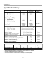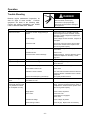
1
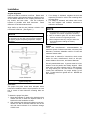
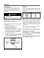
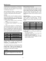
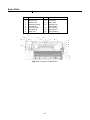
Induction Motors/ Generators Horizontal – Medallion 500, 580, 880, SH400, SH450, SH560 Frames TEFC Enclosures Type CZ, NCZ, CGZ, CMZ, NCMZ, 1LA4 ANIM-03522-0814 (Supercedes all previous issues of ANIM-03522) ©2014 Siemens Industry, Inc. All rights reserved. Installation Operation Maintenance Table of Contents TABLE OF CONTENTS SAFETY PROCEDURES INTRODUCTION Warranty Receiving Handling Temporary Storage Type Designations INSTALLATION Motor Dimensions Location Foundation Mounting Coupling of Sleeve Bearing Motors External Wiring Changing Direction of Rotation Alignment Hot Alignment Vibration Doweling Force Feed Lubrication Oil Mist Purge Typical Motor Control Settings Page 1 2 3 3 3 4 4 4 5 5 5 5 5 5 6 6 6 8 8 9 9 9 10 OPERATION Initial Start Oil Circulating Systems Normal Operation Voltage/Frequency Variation Trouble Shooting MAINTENANCE Preventive Maintenance Inspection Hazardous Location Corrective Maintenance Rotor Cleaning Stator Cleaning Insulation Resistance Drying Insulation Bearings Bearing Lubrication Bearing Replacement SPARE PARTS Identification MOTOR SERVICE RECORD VIBRATION ANALYSIS SHEET NOTES Page 11 11 11 11 11 12 14 14 15 15 16 17 17 17 17 18 21 22 26 26 31 32 33 Note - These instructions do not purport to cover all details or variations in equipment, nor to provide for every possible contingency to be met in connection with installation, operation or maintenance. Should further information be desired or should particular problems arise which are not covered sufficiently for the user’s purposes, the matter should be referred to; 1. Your local Siemens Sales Office. --Or-2. Siemens Technical Support Communication Center: Inside the U.S.: 1-800-333-7421 Outside the U.S.: +1 423-262-5710 Online: www.industry.usa.siemens.com/industry and click on Industry Services The contents of this instruction manual shall not become part of or modify any prior or existing agreement, commitment or relationship. The sales contract contains the entire obligation of Siemens. The warranty contained in the contract between the parties is the sole warranty of Siemens. Any statements contained herein do not create new warranties or modify the existing warranty. Siemens machines are built in accordance with the latest applicable revision of the National Electric Code, Underwriters Laboratories Standards and Procedures, and NEMA (National Electrical Manufacturers Association) Standards. These publications and this instruction manual should be thoroughly read and understood prior to beginning any work on this equipment. The information contained within is intended to assist operating personnel by providing information on the general characteristics of the purchased equipment. It does not relieve the user of the responsibility of using accepted engineering practices in the installation, operation and maintenance of this equipment. Should a conflict arise between the general information in this manual and the contents of the drawings and supplementary material, the latter shall take precedence. The illustrations in this book show typical machines. Special features deviate from those pictured. -1- Safety Procedures This equipment contains hazardous voltages. Death, serious personal injury or property damage can result if safety instructions are not followed. Do not operate this equipment in excess of the values given on nameplate or contrary to the instructions contained in this manual. The equipment (or a prototype) has been factory tested and found satisfactory for the condition for which it was sold. Operating in excess of these conditions can cause stresses and strains beyond design limitations. Failure to heed this warning may result in equipment damage and possible personal injury. The successful and safe operation of motors and generators is dependent upon proper handling, installation, operation and maintenance, as well as upon proper design and manufacture. Failure to follow certain fundamental installation and maintenance requirements may lead to personal injury and the failure and loss of the motor as well as damage to other property. DANGER Hazardous voltage. Only qualified personnel should work on or around this equipment after becoming thoroughly familiar with all warnings, safety notices and maintenance procedures contained herein. Only qualified personnel should be involved in the inspection, maintenance and repair procedure and all plant safety procedures must be observed. Will cause death, serious injury, electrocution or property damage. Disconnect all power before working on this equipment. NOTE Qualified Person: For the purpose of this manual and product labels, a Qualified person is one who is familiar with the installation, construction and operation of the equipment, and the hazards involved. In addition, he or she has the following qualifications: Squirrel cage induction machines can be driven by various types of prime movers. These will act as induction generators. This instruction manual applies to both motors and induction generators. However, for clarity reasons, the machine will be referred to as a “motor”. a. Is trained and authorized to energize, de-energize, clear, ground and tag circuits and equipment in accordance with established safety practices. b. Is trained in the proper care and use of protective equipment, such as rubber gloves, hard hat, safety glasses, face shields, flash clothing, etc., in accordance with established safety practices. c. Is trained in rendering first aid. Danger: For the purpose of this manual and product labels, Danger indicates an imminently hazardous situation which, if not avoided, will result in death or serious injury. Warning: For the purpose of this manual and product labels, Warning indicates a potentially hazardous situation which, if not avoided, may result in minor or moderate injury. Caution: For the purpose of this manual and product labels, Caution indicates a potentially hazardous situation which, if not avoided, may result in minor or moderate injury. It is also used to alert against unsafe practices. Motors should be installed and grounded per local and national codes. -2- Introduction temporary film of rust inhibiting oil or, when a motor is supplied specifically with “provisions for oil mist lubrication” (oil supply system furnished by the user), the motor is shipped from the factory with grease in the bearings. DANGER Hazardous voltage. Will cause death, serious injury, electrocution or property damage. Disconnect all power before working on this equipment. When receiving a motor with sleeve bearings: 1. Remove shaft blocking materials. 2. Visually inspect bearing condition through sight glass and bearing drain opening. 3. Check for moisture accumulation. Remove any traces of oxidation before putting the motor into service. 4. Fill bearing reservoirs to normal level with a high grade industrial lubricating oil. See Maintenance Section of this instruction book to determine proper oil level. 5. Rotate the shaft a minimum of 10 complete turns by hand to distribute oil over bearing parts. Make sure the oil rings in each bearing rotate freely. These instructions present general recommendations for installation, operation and maintenance of induction motors built at the Norwood plant. If additional information is required, contact Siemens Industry. Warranty See your sales contract for warranty coverage. Documentation of storage maintenance, alignment and regreasing may be required for certain warranty considerations. When receiving a motor with grease lubricated anti-friction bearings: Motors having grease lubricated antifriction bearings are shipped with the bearings already lubricated and ready for operation. Receiving Motors are shipped in first class condition. They have been inspected and are skidded to prevent damage from ordinary handling during shipment. If the elapsed time from the time of shipment to the time in which the unit is to be started is in excess of thirty (30) days, regrease per the lubrication plate mounted on the motor. Inspect new motors for shipping invoice. Make the examination before removing from cars or trucks. If damage or indication of rough handling is evident, file a claim with the carrier at once, and notify your Siemens sales representative. When receiving a motor with oil mist lubricated anti-friction bearings: 1. Be sure that the motor is not stored outdoors. 2. Be sure that the oil mist lubrication is connected and operating before starting the motor. 3. The oil mist lubrication should be in operation within two weeks after the motor is received from the factory. Remove only the shipping invoice. Do not remove tags pertaining to lubrication, operation and storage instructions. Read and follow all instructions to insure that no damage to motor bearings, (due to condensation) and motor windings occurs during storage. Use care in handling. Dropping the motor or otherwise imposing shock loads can cause unseen and undetected damage to bearings. This damage such as false brinelling of the races of anti-friction bearings can result in early bearing failure. When receiving a motor with “provisions for oil mist lubrication”: 1. Leave the grease in the bearings if the motor is to be stored. 2. Before operating the motor with oil mist lubrication, disassemble the motor, and clean the grease from bearings, end caps, and the bearing housing cavities with a suitable solvent. If supplied, energize space heaters to help prevent condensation within the motor enclosure. Motors having sleeve bearings or oil lubricated antifriction bearings are shipped WITHOUT OIL in the bearing reservoir. These bearings and journal surfaces are protected during shipment by a -3- Introduction Temporary Storage WARNING Heavy equipment. Improper handling may cause death, serious injury or property damage. Check lifting devices before lifting. Use proper slings, chains and spreaders. Note any warning plates on motor and follow instructions on each plate. Handling Lifting devices are provided for handling only. An experienced rigger should be used to install motors. To avoid damage, the use of spreader bars is recommended on other than single point lifts. Lifting devices are provided to facilitate handling with shackles and cables. Avoid pounding or bumping shaft, coupling or bearing parts, as shocks may damage bearings. If the equipment is not to be installed and operated soon after arrival, store it in a clean, dry, wellventilated place, free from vibration and rapid or wide variations in temperature. Rotate the shaft a minimum of 10 complete turns by hand each month to coat the bearings with lubricant which will retard oxidation or corrosion, and prevent possible false brinelling. If drain plugs are provided in enclosed motors, they must be removed periodically to drain any water accumulation from the motor. Consider a unit in storage when: 1. It has been delivered to the job site and is awaiting installation. 2. It has been installed but operation is delayed over 30 days pending completion of plant construction. 3. There are long (30 day) periods between operating cycles. 4. The plant (or department) is shut down for 30 days. NOTE Storage requirements vary, depending on the length of storage and the climate. For storage periods of thirty (30) days or longer or climate variations, consult Siemens Storage Recommendations ANIM-03114. Storage maintenance is to be documented for warranty information. NOTE WEIGHT BEFORE LIFTING. The weight is indicated on the outline drawing. Apply tension gradually to cables. Do not jerk or attempt to move the unit suddenly. Motor Weights (in pounds) Frame Size Minimum Maximum 500 3300 5300 580 4600 6700 880 15800 19700 SH400 8200 9900 SH450 11500 13700 SH560 18078 22267 Type Designations The motor type designation consists of a basic letter or letters indicating the motor enclosure type to which other letters may be added denoting modifications. -4- Motor Type Motor Enclosure CZ, NCZ, CGZ, CMZ, CMZ, or 1LA4 Totally-Enclosed Fan Cooled Installation Motor Dimensions For motors built in the frame sizes covered by this manual, the letter dimensions have the same definitions as established NEMA standards. Established dimensions for these frames may be found on catalog sheets or certified drawings. CAUTION Before pouring, locate foundation bolts by use of template frame and provide secure anchorage (not rigid). It is recommended that a fabricated steel base be used between motor feet and foundation. See certified drawings of motor, base, and driven unit for exact location of foundation bolts. Allow for grouting base when pouring. Cast the base footpads level and in the same plane. Mounting Damp Location. Mount the motor base (if used) on foundation or other support. Shim as required to level. Use laser or spirit o level (check two directions at 90 ) to insure motor feet will be in one plane (base not warped) when base bolts are tightened. Set motor on the base, install nuts and tighten. DO NOT TIGHTEN UNTIL AFTER ALIGNMENT. Can cause property damage if equipment is operated intermittently. Use space heaters to prevent dampness. Grease machine fits when unit is reassembled to prevent corrosion. Location Select a location for the motor and driven unit that will: 1. Be clean, dry, well ventilated, properly drained, and provide accessibility for inspection, lubrication and maintenance. 2. Provide adequate space for motor removal without shifting the driven unit. 3. Permit the motor to safely deliver adequate power. Temperature rise of a standard motor is based on operation at an altitude not higher than 3,300 feet above sea level. 4. Avoid condensation of moisture in bearings and on windings. Motors should not be stored or operated in areas subject to rapid temperature changes unless motors are energized or protected with space heaters. Foundation Concrete (reinforced as required) makes the best foundation, particularly for large motors and driven units. In sufficient mass it provides rigid support that minimizes deflection and vibration. It may be located on soil, structural steel, or building floors provided the total weight (motor, driven unit, foundation) does not exceed the allowable bearing load of the support. Allowable bearing loads of structural steel and floors can be obtained from engineering handbooks. Building codes of local communities give the recommended allowable bearing loads for different types of soil. For rough calculation the foundation should be approximately 2-1/2 times total unit weight. NOTE Experience has shown that any base-mounted assemblies of motor and driven units temporarily aligned at the factory may twist during shipment. Therefore, alignment must be checked after mounting. Realignment is to be documented for warranty information. Coupling of Sleeve Bearing Motors Sleeve bearings cannot withstand externally generated axial thrust. Antifriction bearings are normally designed to handle a minimum thrust. As the motor and driven equipment get hot they may expand towards each other and with the wrong coupling this could produce an axial force. Therefore, the selection of coupling is of extreme importance. If properly installed, the following types of couplings are considered to be free from the development of axial thrust and may be used: 1. Laminated Metal Disk Type 2. Rubber Biscuit Type (Designed for the Speed) Limited end float models of the following types are available from several coupling manufacturers and may be used by selecting the proper end float (See “End Float – Sleeve Bearings” under Bearing Replacement) 3. Pin and Bushing Type 4. Gear Type -5- Installation External Wiring Motor Fan Direction Motor Speed Frame DANGER 3600 – 3000 RPM 1800 – 1500 RPM 1200 RPM & SLOWER 500 Hazardous voltage. Will cause death, serious injury, electrocution or property damage. Disconnect all power before working on this equipment. 580 SH400 NON-DIRECTIONAL SH560 NOTE 880 DIRECTIONAL Before running motor, see Initial Start. SH450 Starting and overload control devices must be matched to motor rating. For safety or convenience they may need to be installed some distance from the motor. Follow the control manufacturer’s instructions to make proper installations and connections. Observe the following: 1. Connect electrical power supply to conform with National Electric Code and any local regulations. Line voltage and wire capacity must match motor rating stamped on the nameplate. 2. With the driven equipment disconnected, momentarily energize the motor to check rotation. 3. If motor is three-phase type, reverse rotation (if required) by interchanging any two of the three power leads. NOTE It will be necessary to rebalance the rotor if the fans are changed. Alignment Accurate shaft alignment between motor and driven equipment is essential. Improper alignment may result in vibration, bearing overloads and excessive shaft stresses. Flexible couplings will not compensate for excessive misalignment. NOTE Changing Direction of Rotation Look for rotation plates usually mounted on fan housing of the motor. A basic rule is to not have more than five shims in a shim pack under any one motor foot. Thick shim packs consisting of many thin shims will cause soft foot, excessive vibration or twisted frame (motor foot out of plane). CAUTION Excessive heat. Motor may overheat if motor cooling fans run in the wrong direction. Run motor in direction shown on motor or change fans. External fan direction must be considered if changing direction of rotation is contemplated on motors equipped with shaft mounted external fans. See the following Motor Fan Direction table to identify which motors have directional external fans. All directional fans must be replaced with a fan designed for the desired direction of rotation. Parallel Alignment After positioning unit for correct end float, separate the coupling halves and mount a dial indicator rigidly on one coupling half with the button on the cylindrical surface of the other half. Rotate the shafts together, and take readings at top, bottom and side positions. Align shaft so difference between top and bottom readings and the side readings is a maximum of 0.002 inch for a flexible coupling. -6- Installation Angular Alignment Hold each shaft at maximum end float. Rotate both shafts together, and measure between matching points at the outside diameter of the coupling faces for the top, bottom and both sides. Use two indicators because of possible axial shaft movement. Read difference of variation between them. 3. If no change is indicated, retighten the bolt and repeat the process for each of the remaining three mounting bolts. 4. If a change is indicated, add shims under motor foot and retighten until indicator movement is reduced or eliminated. Align shafts so that the total indicator variation does not exceed 0.002 inch. (See Figure 1.) NOTE 1. NOTE 2. If vibration levels increase cold to hot, alignment should be checked hot to verify that motor and driven equipment are properly aligned at operating temperature. Adjust if necessary. 3. The foot plane is of concern for each unit of rotating equipment. Check driven equipment if necessary. Base or foundation rigidity can also affect vibration; check for resonance in supporting structure. Recheck alignment after any change in shims and document alignment readings for warranty information. V-Belts Check belt manufacturer’s recommendations for maximum speed of sheaves and belts, minimum pitch diameters, maximum allowable number of belts and maximum sheave width. When motor is ordered for V-belt drive, check motor outline for motor manufacturer’s limits on belt pull, sheave distance from motor, and sheave diameter. Use only matched-belt sets. V-grooves must be in line; sheaves must be parallel and axially aligned. Belts must enter and leave sheaves with no side bending. For long bearing life, the belt tension is important; consult belt manufacturer for proper tension to suit drive. Protect belts from grease and oil. NEVER use belt dressing. Figure 1. Diagrams Showing Parallel and Angular Misalignment Foot Plane The proper foot plane exists when adequate shims have been installed to assure equal pressure on each foot or corner of motor when the mounting bolts are loose. To determine proper foot plane: 1. Mount dial indicator on shaft to be checked so that contact will rest on either the adjacent shaft or a bracket from the foundation or base. 2. With mounting bolts tight and indicator set at zero, release one bolt at the shaft extension end of the unit and check indicator for a maximum change of 0.001 inch. -7- Installation Hot Alignment Vibration It is possible for the motor shaft height to change relative to the driven equipment and this should be compensated for during the alignment procedure. Heat from driven equipment can also cause horizontal misalignment. The standard unfiltered housing vibration limits measured at no load, uncoupled, and with rigid mounting are as follows based on the requirements of NEMA MG1-7.8. Speed 1200 – 3600 RPM 1000 RPM 900 RPM 750 RPM 720 RPM 600 RPM WARNING Rotating parts. Can cause serious injury. Disconnect and lock out power before working on equipment. If motor application is abnormal (high temperature, extreme vibration, etc.) consult the factory for special instructions or additional information. Check for vertical alignment (parallelism) of coupled drive as follows: 1. Operate unit until normal temperature is reached (may require several hours). 2. Shut down motor and lock out switch. 3. Mount dial indicator as in Figure 2. 4. Rotate shaft, noting readings at 0°, 90°, 180°, and 270° (both sides, top, and bottom). If within 0.002 inch total indicator reading, or other limit specified by the factory, unit is satisfactory for operation. 5. If not within limits, add or remove shims as required to raise or lower motor. 6. If shims are changed for high temperature operation, repeat alignment procedure to extent necessary to assure proper alignment. Document readings for warranty information. Velocity, inches/sec peak 0.120 0.105 0.096 0.079 0.075 0.063 After alignment is complete and foot mounting bolts are tight, run motor at no load (or minimum possible). Check for vibration. If excessive vibration exists and the alignment is acceptable, check foot plane by loosening one drive end-mounting bolt at a time as detailed below. This is to be documented for warranty information. When resiliently mounted, allowed levels are 25% higher. Base or foundation rigidity can also affect vibration; check for resonance in supporting structure. Recheck alignment after any change in shims and document alignment readings for warranty information. Completing Mechanical Installation After controlling rotor end float and establishing accurate alignment, it is recommended to drill and ream the foundation plate and motor feet together for dowel pins. (See Doweling). Recheck parallel and angular alignment before bolting the coupling together. Motor shaft should be level within 0.03 inch after alignment. Figure 2. Check of Vertical Alignment -8- Installation Doweling Doweling the motor (and driven unit) accomplishes the following: 1. Restricts movement. 2. Eases realignment if motor is removed from base. 3. Temporarily restrains the motor, should mounting bolts loosen. Inserting Dowel Pins The following procedure is recommended: a. Check the alignment after the unit has been in operation approximately one week. Correct as necessary. b. Using pre-drilled dowel holes in motor feet as guides, drill into the mounting base. c. Ream holes in the feet and base to the proper diameter for tapered dowel pins. Clean out the chips. d. Insert dowel pins. Force Feed Lubrication If force feed lubrication is used, flush lubrication lines thoroughly to make sure the lines are clean before connecting lines to bearing housings. Be sure that bearing cavities are filled with oil to the proper level before starting. See motor outline drawing to determine proper oil level. Be sure that proper oil pressure and flow are provided by the supply system. Verify that the oil drain flow agrees with the factory requirements. The orientation and size of oil drain piping supplied with the motor must not be altered. Oil drain piping should be of the same size or larger from the motor piping to the oil sump. Piping must slope downward. Pressure build up in the drain line between the oil sump and the motor bearing housing can lead to oil leakage. Document readings for warranty information. Oil Mist Purge When connecting 500/580 frame motors for oil mist purge, it is important to note that the drive and nondrive end bearing cavities operate at different pressures. To avoid high or low oil levels, care should be taken when connecting the system so that cavity pressures are maintained. -9- Installation Typical Motor Control Settings Alarm Trip (Shutdown) Winding Temperature • Class B Insulation • Class F Insulation 130°C 155°C 155°C 170°C Motor Bearing Temperature (Thermocouple or RTD’s) • Sleeve Bearing • Antifriction Bearing 100°C 100°C 105°C 105°C 4 Amps (2) Primary Circuit 8 Amps (2) Primary Circuit Ground Fault Timer Trip Setting (1) 0.2 sec. (2) Instantaneous Overcurrent • • 1.8 times Locked Rotor Amps (2) 2.4 times Locked Rotor Amps (2) With ½ Cycle Delay Without Time Delay Maximum Voltage Minimum Voltage (the minimum voltage 110 % of Rated Voltage 10 sec. 90 % of Rated Voltage 10 sec. Maximum Frequency Deviation ±5% 10 sec. Maximum of Voltage Plus Frequency Deviation ±10% 10 sec. Maximum Voltage Unbalance (3) 1% 15 sec. Maximum Current Unbalance (3) 8% 15 sec. Suggested Vibration Limits 3600 1800 1200 3.3 0.25 4.3 0.25 900 and Slower 5.0 0.25 also applies to starting unless otherwise specified) RPM Shaft (mils, pk-to-pk) Housing (in./sec.) 3.7 0.25 (1) Maximum time at maximum condition before control device is to operate. Increase as necessary to avoid nuisance trips. (3) This is the maximum deviation from the average of the three phases. (2) - 10 - Operation Initial Start Oil Circulating Systems For motors with oil circulating systems, proceed as follows before startup; CAUTION Do not exceed number of Siemens specified hot and cold starts per hour. 1. Fill motor reservoirs to normal level (see motor outline drawing). 2. Follow instructions provided by the oil circulating system supplier. 3. Put oil circulating system into operation before starting motor. Will cause overheating. Allow time between starts to permit stator windings and rotor cage to cool. NOTE Normal Operation If motor has been out of service or in storage for more than 30 days, consult Siemens Storage Recommendations ANIM-03114, Preparation for Service After installation is completed, but before motor is put in regular service, make an initial start as follows: 1. Check that motor, starting, and control device connections agree with wiring diagrams. 2. Check that voltage, phase, and frequency of line circuit (power supply) agree with motor nameplate. 3. Check motor service record and tags accompanying motor. Be certain bearings have been properly lubricated and oil wells are filled. See motor outline drawing to determine proper oil level. 4. If possible, remove external load (disconnect drive) and turn shaft by hand to assure free rotation. This may have been done during installation procedure; if so, and conditions have not changed, this check may not be necessary. 5. If drive is disconnected, run motor at no load long enough to be certain that no unusual condition exists. Listen and monitor for excessive noise, vibration, clicking or pounding and that oil rings are turning if so equipped. If present, stop motor immediately. Investigate the cause and correct before putting motor in service. 6. If drive cannot be disconnected, interrupt the starting cycle after motor has accelerated to low speed. Carefully observe for unusual conditions as motor coasts to a stop. Repeat several times if necessary. Refer to motor’s Starting Duty nameplate (if so equipped) or Motor Data Sheet for recommended number of starts and cooling period between starts. 7. When checks are satisfactory, operate at lowest load possible and look for any unusual condition. Increase load slowly to maximum, checking unit for satisfactory operation. Start the motor in accordance with standard instructions for the starting equipment used. Sometimes the load should be reduced to the minimum, particularly for reduced voltage starting, and/or high inertia connected loads. Voltage/Frequency Variation Motors will operate successfully under the following conditions of voltage and frequency variation, but not necessarily in accordance with the standards established for operating under rated conditions: 1. If the variation in voltage does not exceed 10% above or below rated voltage, with all phases balanced. Voltage unbalance should not exceed 1%. 2. If the variation in frequency does not exceed 5% above or below rated frequency. 3. If the sum of the voltage and frequency variations does not exceed 10% above or below rated values provided the frequency variation does not exceed 5%. - 11 - Operation Trouble Shooting DANGER Hazardous voltage. Between regular maintenance inspections, be alert for signs of motor trouble. Common symptoms are listed in the following table. Correct any trouble immediately and AVOID COSTLY REPAIR AND SHUT DOWN. TROUBLE Motor will not start. Will cause death, serious injury, electrocution or property damage. Disconnect all power before working on this equipment. POSSIBLE CAUSES CORRECTION Usually line trouble. Single phasing at starter. Check power source. DO NOT check with motor energized! Check overloads, controls and fuses. Check voltage and compare with nameplate rating. Under Voltage. Check voltage at motor terminals. Compare to nameplate. Excessive Load. Disconnect motor from load to see if it starts without load. Reduce load or replace motor with unit of greater capacity. High Voltage. Check input voltage. Check for proper connections. Unbalanced rotor. Balance rotor. Excessive wear of sleeve bearings. Replace bearings. Check to determine cause of wear and replace as necessary. Check alignment. Regular clicking. Foreign matter in air gap. Remove foreign matter. Rapid knocking. Bad anti-friction bearing or dirt in lubricant. Replace bearing, clean grease cavities and renew lubricant. Vibration. Misalignment in coupling or feet. Realign motor and driven equipment. Accumulation of dirt on fan. Clean motor. Vibration in driven machine. Run motor disconnected from driven load and check for vibration. Eliminate source in driven equipment. Excessive hum. System natural frequency (resonance). Alter rigidity of base structure. Vibration following motor repair. Rotor out of balance; balance weights of fans shifted on rotor. Balance rotor. Motor overheating. (Check with thermocouple or by resistance method, do not depend on touch). Overload. Measure load and compare with nameplate rating. Check for excessive friction in motor or complete drive. Reduce load or replace motor with unit of greater capacity. Single phase. Check current, all phases. Dirt in motor. Check flow of air. Check filters if so equipped. Clean motor. Unbalanced voltage. Check voltage, all phases. Rotor rubbing on stator. Check air gap. Repair motor as necessary. - 12 - Operation Trouble Shooting DANGER Hazardous voltage. Will cause death, serious injury, electrocution or property damage. Disconnect all power before working on this equipment. TROUBLE Motor overheating (continued…) POSSIBLE CAUSES CORRECTION Open stator windings. Disconnect motor from load. Check idle amps for balance in all three phases. Check stator resistance in all three phases for balance. Air Recirculation. Check air intake and exhaust for obstructions. Check air inlet temperature. Over voltage/under voltage. Check voltage and compare to rating plate. Ground. Locate with test lamp or insulation tester and repair. Improper electrical connections. Recheck electrical connections. Heat exchanger tubes blocked. Clean tubes, if so equipped. Loose heat exchanger tubes. If so equipped, Roll tubes to expand tube inside diameter using proper expansion tool. Fine dust under coupling having rubber buffers or pins. Misalignment. Realign motor and driven equipment. Inspect coupling. Bearing overheating. Oil level too high or low (sleeve bearing). Correct oil level. See Maintenance section of this instruction book to determine proper oil level. Misalignment. Realign motor and driven equipment. Excessive tension in belt drive. Reduce tension to point of adequacy. Excessive end thrust. Reduce thrust. Recheck mounting and alignment. Too much grease (ball or roller bearing). Relieve supply to point set by manufacturer. Sticking oil ring (sleeve bearing). Clean, repair, or replace. Recheck mounting. Parts not sealed properly. Seal pipe plugs and connections. Seal bearing housing split line. Seal oil seal joint. Clogged oil return holes in oil seals. Dismantle and clean oil seals. High pressure or vacuum in bearing cavity. Measure pressure or vacuum using manometer (See “Cavity Pressures” under Bearings). Oil leakage or excessive oil usage. Excessive oil level fluctuation. Check atmospheric vents for obstructions. Check oil seal gap for uniformity. - 13 - Maintenance Preventive Maintenance Motors are designed to give many years of reliable service with a minimum of attention. Trouble-free operation cannot be expected if proper maintenance is postponed or neglected. Provide proper maintenance on the equipment. Follow carefully the instructions contained herein. Be certain personnel review, understand, and follow these procedures during periodic maintenance inspections. DANGER Hazardous voltage. Will cause death, serious injury, electrocution or property damage. Disconnect all power before working on this equipment. Maintenance should be performed only by qualified personnel. CAUTION Flying dirt, dust or other particles. May cause eye injury. Wear safety glasses and dust mask when using compressed air. CAUTION Maintenance Checklist 1. Verify motor is clean and verify that stator and rotor ventilation passages are unobstructed. 2. Check for excessive loading or service factor. 3. Verify winding temperature rise not in excess of rated value. 4. Verify insulation resistance is above recommended minimum. 5. Verify voltage and frequency variation. 6. Check air gap. 7. Verify that bearing temperatures are within limits and that lubricant is clean and proper level maintained. 8. Verify no unusual vibration or noise exists. 9. Check alignment. 10. Check for proper lubrication. A definite schedule of preventive maintenance inspections should be established to avoid breakdown, serious damage and extensive downtime. The schedule will depend on operating conditions and experience with similar equipment. To assure adequate maintenance, and warranty consideration, it is essential that complete records be kept for each motor, including description and rating, maintenance schedule and repairs required or carried out. This checklist does not represent an exhaustive survey of maintenance steps necessary to ensure safe operation of this equipment. Particular applications may require further procedures. Should further information be desired or should particular problems arise which are not covered sufficiently for the purchaser’s purposes, the matter should be referred to the local Siemens Sales Office. Loose parts or fire. Can result in product failure or serious property damage. WARNING Improper maintenance can cause death, serious injury or property damage. Use only factory authorized parts for repair of equipment. Maintenance should be performed only by qualified personnel. - 14 - Maintenance Hazardous Location WARNING Explosion or fire. Can cause death, serious injury or property damage. Do not modify or change any motor accessories, which are not suitable for the area classification. Any part replacements are accurate duplicates of the original to maintain the hazardous area classification. Consult manufacturer for the replacement part and for repair process. Inspection Each motor should be inspected at regular intervals. The frequency and thoroughness will depend on the operating hours, nature of service, and the environment. Sleeve Bearing - 580, 880, SH400, SH450, SH560 Frames Access to the motor interior can be gained by removal of the bearing bracket as follows: 1. First remove the bearing housing cap and bearing liners as described under Bearing Replacement. 2. Remove floating labyrinth seals or oil seals as equipped. 3. Remove the bearing housing from the bearing bracket. 4. Carefully remove the bearing bracket with inner motor seal from the motor. Cleanliness The exterior should be kept free of oil, dust, dirt, water, and chemical. It is particularly important to keep the air intake and exhaust openings free of obstructions. NOTE Antifriction Bearing Access to the motor interior can be gained by removal of the bearing housing. 1. Remove the bolts holding the inner bearing end cap to the housing. 2. Remove the bolts holding the bearing housing to the yoke. 3. Remove the bearing housing by pulling it away from the face of the yoke. It will be necessary to first remove the fan housing and external fan from the non-drive end of the motor to gain access to the bearing housing. Sleeve Bearing - 500 Frame Access to the motor interior can be gained by removal of the upper half of the horizontally split bearing bracket. If equipment is operated intermittently in very damp locations, it should be protected by space heaters. To retard corrosion, grease all machined fits when the unit is reassembled after a maintenance check. Loading Overloading causes overheating and reduces insulation life. A winding subjected to a 10°C temperature rise above the maximum limit for its class may have its insulation life halved. Underloading a motor is improper as it lowers the motor power factor and efficiency which results in higher power cost. 1. Remove the parting bolts at the horizontal split. 2. Remove the bolts at the outer circumference of the upper half of the split-bearing bracket. 3. Pull the upper bracket away from the face of the frame and remove bracket. The entire procedure can be done without disturbing the bearing enclosure or coupling alignment of the motor to the load. The split-bearing capsule is held together by bolts. - 15 - Maintenance Temperature Electrical apparatus operating under normal conditions becomes quite warm. Although some places may feel hot to the touch, the unit may be within limits. If checking total temperature by winding resistance or imbedded detector (RTD), the total temperature should not exceed the following: When operating at full load: Class of Insulation System Temp. by Resistance Temp. by Embedded Detector B F H All HP 120°C (248°F) 145°C (293°F) 165°C (329°F) 1500HP or less 130°C (266°F) 155°C (311°F) 180°C (356°F) 125°C (257°F) 150°C (302°F) 175°C (347°F) 120°C (248°F) 145°C (293°F) 165°C (329°F) Over 1500HP -Under 7000V Over 1500HP -Over 7000 V Class of Insulation System B F H All HP 1500HP or less Temp. by Embedded Detector Over 1500HP -Under 7000V Over 1500HP -Over 7000 V More important than the actual vibration is the vibration change over a period of time. Corrective Maintenance Two factors that require corrective maintenance are electrical failure or mechanical failure. The first sign of electrical failure is usually low insulation resistance. Mechanical failures are usually preceded by excessive bearing noise or heat. Low Insulation Resistance Factors that usually cause low insulation readings are: When operating at 1.15 service factor load: Temp. by Resistance 4. Foundation construction - Base, grouting and associated equipment supporting drives must be in good condition. Vibration can be amplified by weak construction. Vibration of base just below motor feet should not exceed 25% of motor vibration. 5. History - When was vibration first noted? Was there a change in loading and/or duty of equipment? Has ambient vibration changed? 130°C (266°F) 155°C (311°F) 175°C (347°F) 140°C (284°F) 165°C (329°F) 190°C (373°F) 135°C (275°F) 160°C (320°F) 185°C (365°F) 130°C (266°F) 155°C (311°F) 175°C (347°F) 1. 2. 3. 4. Dirty winding can be cleaned and moist windings dried; however, items 3 and 4 require extensive repairs by a certified service center. CAUTION Flying dirt, dust or other particles. These temperatures represent the maximum temperature for each class of insulation and include a 40°C ambient temperature. Operation above these temperatures will result in reduced insulation life. Vibration Most problems can be detected when inspected visually. Check for; 1. Loose or missing parts, such as fan blades, nuts, bolts, screws, couplings, etc. 2. Accumulation of dirt on fan or rotor. 3. Associated equipment - Disconnect equipment to determine where the vibration is being generated. Dirty windings (oil, dust, grease, salt, etc.). Excessive moisture. Mechanically damaged insulation. Heat deterioration May cause eye injury. Wear safety glasses and dust mask when using compressed air. Cleaning Clean the outside of the motor regularly. Actual conditions existing around the motor dictate the frequency of cleaning operations. Use the following procedures as they apply. 1. Wipe off dust, dirt, oil, water, etc., from external surfaces of the motor. 2. Remove dirt, dust, or other debris from ventilating air inlets and exhausts. Do not operate motor with air passages blocked or restricted. - 16 - Maintenance Rotor Cleaning Drying Insulation Remove rotor. Inspect and clean. Stator Cleaning Micalastic™ form wound VPI (vacuum pressure impregnated) insulated coils may be cleaned with solvent using lint free cloths or steam cleaned with low-pressure steam, then the entire stator oven baked at 170°F for 6 hours and then 245°F for 12 hours. If the insulation resistance is less than satisfactory, and the cause is believed to be excessive moisture in the windings, dry the windings by applying heat from: 1. A warm air oven. 2. Electric strip heaters. 3. Circulating currents through the coils. The heat should be applied slowly so the desired temperature will not be obtained in less than six hours. The stator winding insulation resistance should be measured before and after any cleaning operation. Insulation Drying Temperature* Micalastic™ is a Siemens trademark. DANGER Check insulation resistance periodically. Use a hand cranked or solid state insulation resistance tester and test with at least 500 volts, but not greater than motor rated voltage. For motors with newer insulation systems such as Micalastic™ VPI, the insulation resistance after one minute should be greater than 1000 megohms. (Values in excess of 5000 megohms are common.) For older motors, the minimum value recommended in IEEE Standard 43 can be used. The value in megohms, when corrected to 40°C, is equal to the motor rated voltage in kilovolts plus 1. For example, for a motor with a rated voltage of 2300 volts, the limit value would be + 1 = 3.3 (megohms). 200°F 245°F* 275°F* 94°C 118°C 135°C NOTE High Voltage. Insulation Resistance Class “H” Insulation resistance should be measured before the heat is applied, and every six to eight hours thereafter. CAUTION May damage semi-conductors, small transformers, voltage regulators, and other devices. Disconnect from circuit before testing insulation resistance. Class “F” *Class “F” and “H” insulated units should be baked at 70% specified temperature (to avoid steam inside winding) for about six hours, before temperature is raised to drying temperature. Hazardous voltage. Will cause death, serious injury, electrocution or property damage. Disconnect all power before working on this equipment. Class “B” Insulation resistance will decrease as the motor warms up; but will begin to increase as the drying process continues. A uniform temperature must be maintained in the motor to obtain constant resistance readings. When the megger readings remain constant, the drying process is complete and may be discontinued. Check for other causes if readings are still low. Warm Air Oven Drying 1. Remove bearing housings. 2. Remove rotor. Bake in oven at temperatures specified in Insulation Drying Temperature table, and follow procedures described for drying insulation. - 17 - Maintenance Electric Strip Heater Drying 1. Remove bearing housings. 2. Remove rotor. 3. Direct a fan on stator to carry away the moisture. 4. Attach temperature indicators to winding and apply heat as specified in the Insulation Drying Temperature table and follow procedures described for drying insulation. 5. Radiant type heaters are not recommended because some parts may become scorched before remote parts reach desired temperature. Circulating Current Drying 1. Remove bearing housings. 2. Center the rotor in the stator core. 3. Wedge fiber strips into the lower part of the air gap so rotor does not touch stator core, or remove rotor. 4. Direct fan on unit to blow away excessive moisture. 5. Attach temperature indicators to windings. Do not exceed the drying temperatures in the Insulation Drying Temperature table. 6. An external source of current can be used to circulate direct current through the winding of any type of alternating current motor. A portable low voltage motor-generator set, such as is used for welding, is usually suitable. When this method is used on the stator, the stator phases may be connected in series or in parallel to suit the available power supply if both ends of all phases are accessible. If only three leads are brought out of the motor, the current may be circulated between one terminal and the other two connected together. If this is done, the temperature of the single lead connection must be checked frequently, and it is desirable to shift the leads occasionally. Usually 50 to 100% of full load current will produce the required temperature. The dc voltage required for this current will be 0.25 - 5.0% of the normal voltage per phase, and the corresponding power will be 0.50 - 3.25% of the rating. Alternating current can be used on the stators of squirrel cage induction motors if the rotors are removed. Alternating current is usually not as easy to control as required voltage control, and a.c. requires a higher voltage source, approximately 10 to 30% of the rated winding voltage. In addition, care must be taken that miscellaneous parts adjacent to the windings, such as lead studs, core supporting member, etc., do no overheat due to induced currents and the lack of normal ventilation. CAUTION High temperatures. May cause damage to insulation. Avoid hot spots and radiant type heat Bearings Long life of bearings is assured by maintaining proper alignment, belt tension, and lubrication at all times. Incorrect alignment of solid and flexible couplings can cause excessive load on bearings, and excessive vibration and thrust. Misalignment of belt drives can cause thrust or harmful shaft oscillation. Improper alignment of gear drives will produce shock loads and may bend the shaft. Excessive belt tension often causes overheating and failure of bearings. Bearings tend to overheat when pulley centers are too close, pulley diameters are too small, or belt speed is too high. Bearing Construction Two types of bearings are employed in induction motors. These are; 1. Antifriction bearings. 2. Sleeve bearings. The type of bearing mounting and supporting structure will depend upon the type of bearing. Bearing housing construction will also vary with the type of bearing. Antifriction bearing motors have one piece bearing bracket construction. Sleeve bearing motors have split bearing housings. - 18 - Maintenance Insulated Bearings One or both bearings may be insulated to prevent shaft currents from pitting bearing surfaces. The insulation is located at the joint between the bearing housing or bracket and the bearing. Insulated bearings are designated by an instruction plate on the bearing housing. Check periodically to be sure the insulation has not been weakened or destroyed. The bearing insulation can be checked using an ohmmeter or circuit test light. For sleeve bearing motors with one bearing insulated, the shaft must be raised a few mils at the non-drive end of the motor so that it is not in contact with the bearing and the shaft coupling must be parted so that the shaft is not grounded through the driven equipment. For motors with both bearings insulated, disconnect bearing grounding strap before testing for insulation integrity. Bearing temperature devices must be disconnected and oil rings must not be in contact with both the shaft and the bearing. Antifriction Bearings Antifriction bearings are selected to give long service when they are given proper maintenance. Bearing failure can be caused by too little or too much lubrication, contamination, excessive bearing load, improper installation, alignment, or vibration. The symptoms of antifriction bearing failure are excessive vibration, noise, and excessive heat generation. The races and balls should be periodically inspected for damage. Any damage requires replacement of the bearing. Sleeve Bearings Check sleeve bearings daily to be sure the oil rings are turning properly. See motor outline drawing to determine proper oil level. Add oil through the oil ring sight glass opening or oil inlet pipe, if so equipped. Be careful not to overfill. Drain the oil reservoir by removing pipe plug. Clean and flush with solvent and refill with fresh filtered oil every three months to one year, depending on severity of service. Use a high grade turbine oil having a viscosity of 300-350 SSU at 100°F for units of 1800 rpm and lower, and 140-160 SSU at 100°F for machines above 1800 rpm to 3600 rpm. In addition, seasonal oil changes are desirable if unit is subject to wide variations in temperature. Bearing babbitt temperatures that exceed 90°C (194°F) or a sudden rise in temperature should be investigated. Common causes of hot bearings are: 1. 2. 3. 4. 5. 6. 7. 8. 9. Lack of oil. Incorrect viscosity. Poor quality oil. Inoperative oil ring. Misalignment of couplings or bearings. Insufficient bearing clearance. Oil seal rubbing on shaft. Shaft or bushing rough spots. Plugged oil passages on circulating oil systems. (Note that circulating oil systems include a filter in the oil line to strain the oil after it leaves the pump. Check and clean or replace filter when necessary.) 10. End thrust on bearing face. Sleeve bearings are bored to an even dimension and shaft journals are slightly smaller to obtain running clearance. Side reliefs are provided to distribute oil axially and reduce friction. During normal operation, the shaft is supported on an oil film 0.001 to 0.005 inch thick, depending on speed, load and viscosity. Unless adverse conditions exist which tend to break down the oil film, metallic contact occurs only during starting and stopping. Under normal circumstances, bearing wear is very small. Oil Rings Inspect oil level and oil ring operation frequently. Oil ring operation can be observed through the oil sight glass. Oil rings should be perfectly round, free of burrs or rough edges, turn at a constant speed, and carry a noticeable amount of oil to the top of the bearing journal. Failure of the oil ring to turn freely may be caused by: 1. Ring out of round - rings should be round within 0.062 inch. 2. Fouling on a projection of the bearings, bushing, or housing. 3. Ring not balanced (heavy side will tend to remain down). 4. Adhesion to guide slot (trapezoidal section reduces adhesion). 5. Oil too cold, too viscous, or oil level too high. 6. Shaft not level – oil rings tend to bind. 7. Vibration causing oil ring to bounce and slow down. - 19 - Maintenance At the first sign of oil discoloration or contamination, replace with new oil. Rapid discoloration is caused by bearing wear, often from vibration or thrust. Change oil as required to keep clean. When assembling the bearing, it is possible to foul the rings so that they will not turn freely. Check ring operation by rotating shaft by hand after assembly Oil Seals 580 frame motors use fixed, labyrinth oil seals to close off the bearing cavity. The 500, 880, SH400, SH450, and SH560 frame motors utilize floating type oil seals to close off the bearing cavity. The primary purposes of the oil seal are: 1. To prevent the entrance of dirt in to the bearing cavity. 2. To retain the oil in the bearing cavity. 3. To provide pressure regulation in the bearing cavity. To achieve these purposes it is necessary that a specific diametrical clearance of oil seal to shaft be held. The cooling fans of the motor tend to create a suction or a pressure in the bearing cavity, which, if large enough, will push or draw oil out along the shaft. The close fitting oil seal gives a pressure drop across it and minimizes the differential pressure. Frame 500 580 880 SH400 SH450 SH560 Standard oil seal clearances Diametrical Clearance 0.008 to 0.015 inches 0.014 to 0.020 inches 0.003 to 0.008 inches 0.003 to 0.008 inches 0.003 to 0.008 inches 0.003 to 0.008 inches Bearing Clearance Too Large Too large a bearing clearance or clogged oil return holes in the bearing will permit excessive oil to seep out the ends of the bearing. This seepage, combined with the rotation of the shaft, will create an oil mist inside the bearing cavity which will tend to leak through the oil seals. Excessive pressure in a force feed lubrication system can also cause an oil mist to build up. Cavity Pressures Motors are sensitive to the amount of pressure or vacuum existing in the bearing cavity. The table below shows the maximum allowable oil cavity pressure or vacuum in terms of plus or minus inches of water: Frame Drive End 500 580 880 SH400 SH450 SH560 ±0.12 ±0.12 ±0.12 ±0.12 ±0.12 ±0.12 Non-Drive End +3.00, -0.12 +3.00, -0.12 ±0.50 ±0.50 ±0.50 ±0.50 For the correction of a high or low reading it is important that: 1. The parts and joints around the bearing cavity and oil seals are sealed. 2. Condensation drains, piping, sight gauges and breathers are functioning properly. 3. Auxiliary equipment extending into the motor must be sealed to prevent a transfer of air from inside to outside the motor. Besides using close clearances to correct differential pressures, some oil seals are vented to the atmosphere. It is important that the piping and venting for these oil seals be kept clean. The clearance between the journal and the bearing will permit the journal center to be slightly below the bearing center. With the motor operating, the presence of the oil film between the journal and the bearing will cause the shaft to rise slightly. NOTE When a sleeve bearing becomes worn and requires replacement, the labyrinth oil seal should also be replaced. - 20 - Maintenance Sealing Parts Even though joints may seem to match perfectly, minute clearances exist through which oil may leak. Sealant should be applied to the mating surfaces of parts where oil is present to prevent seepage of oil. The frequency of lubricating bearings depends on three factors - speed, type of bearing, and service. Sealant should be applied as follows: Lubricate with the type of grease specified on the lubrication plate mounted on the motor, or a compatible grease. Mixing of non-compatible greases can cause bearing failure. 1. Surfaces shall be clean of dirt, grease, and oil sealant. Use a non-oil base solvent if necessary. 2. The mating surfaces should be flat with no nicks or burrs raised above the surface. There should be no gap when mating surfaces are together. Remove all excess paint from parting line surfaces and degrease thoroughly. Do not grind mating surfaces. 3a. For 500, 880, SH400, SH450, and SH560 frames, apply a small bead of silicone RTV at the bearing housing parting surfaces. Loctite 518 may be used in replace of RTV in environments where silicon is prohibited. Do not apply too much sealant as excess will be squeezed out and get into labyrinth seals, bearing, oil cavities, etc. Apply a uniform, thin layer (about 0.05" thick) of Curil T* to the floating oil seal surfaces that mate with the bearing housing. Allow Curil T to cure on the seals for 15 minutes before insertion into bearing housing. 3b. For 580 frames, apply a small bead of silicone RTV to all mating surfaces of parts where oil is present, including fixed oil seals and bearing housing parting lines. 4. Assemble parts. *CURIL-T may be ordered through Siemens Customer Service in Norwood, Ohio. Part number 53-688-487-001 should be used for ordering purposes. Bearing Lubrication Operating environment or application may dictate more frequent lubrication. Higher stator temperatures will result in increased bearing temperatures. Bearing temperatures should not exceed the limits as stated in Typical Motor Control Settings. For specific recommendation, consult factory. Procedure for Lubrication: 1. Stop the motor and lock out the switch. 2. Thoroughly clean the grease inlet fitting or plug. If the motor has plug, remove plug and clean the inlet. 3. Remove the drain plug and clean out any hardened grease. 4. Slowly pump the correct amount of grease into the grease inlet, per the lubrication plate mounted on the motor. 5. Start motor and allow to run at least one (1) hour to expel any excess grease from the drain opening before re-installing the drain plug. 6. Stop the motor and lock out the switch. 7. Re-install the drain plug. 8. Put the motor back in operation. The amount of grease for bearings may be calculated by the following: G = 0.1 x D x B Where: Grease Lubricated Antifriction Bearings NOTE A common mistake is over-lubrication of bearings. When grease is added without removing the drain plug, the excess grease may be forced into and through the inner bearing cap and thrown on to the windings. If bearing is over-lubricated, bearing could run hot, and may lead to failure. All antifriction bearing motors will have an affixed plate with lubricating instructions. The instructions on this plate should be followed to achieve optimum bearing life and to avoid consequential damage to rotating parts. - 21 - G = Amount of grease in fluid ounces D = Outside diameter of bearing in inches B = Width of bearing in inches Maintenance 1. 2. 3. Sleeve Bearings CAUTION 4. Maintain proper oil level. Failure to do so may cause improper lubrication of motor resulting in damage to the equipment. Follow lubrication instructions carefully. Avoid adding oil while unit is running. Motors with sleeve bearings are shipped without oil. A rust-inhibiting film is applied at the factory to protect bearing and journal surfaces during shipment. Before attempting to operate any sleeve bearing motor, the following steps must be performed. 1. Visually inspect the bearing condition. Oil ring inspection ports and drain openings in the housing are normally provided for this purpose. 2. Check for any accumulation of moisture. If oxidation is discovered, all traces of it must be removed before motor is put in service, which will require disassembly. 3. Flush all oil piping. Fill bearing reservoirs to normal level. Fill to mark indicated on gauge or to center of gauge. See the table below for recommended grades of oil. 4. Rotate shaft several turns by hand to distribute oil over bearing parts. Make sure oil rings rotate freely. Recommended Grades of Turbine Oil Motor Speed Oil Viscosity at 100°F ISO Grade 3600 or 3000 RPM 1800 & slower 140 - 160 SSU 300 - 350 SSU 32 68 NOTE The oil viscosity at operating temperature is very important in selecting proper oil and may vary in different climates. It is important to maintain the correct oil level, as lack of lubrication is often the cause of bearing failure. Inspect oil level and oil ring operation frequently. Oil ring operation can be observed through the sight glass mounted at the top of the bearing capsule. Oil rings should be perfectly round, free of burrs or rough edges, turn at constant speed and carry a noticeable amount of oil to the top of the journal. Failure of the oil ring to turn freely may be caused by: 5. 6. Ring out of round (should be round to 0.062 inch) Fouling on a projection of the bearing bushing. Ring not balanced (heavy side will tend to remain down). Adhesion to guide slot (trapezoidal section reduces adhesion). Oil too cold, viscous, or oil level too high. Shaft not level – oil ring tends to bind. At the first sign of oil discoloration or contamination, replace with new oil. Rapid discoloration is caused by bearing wear, often from vibration or thrust. Change oil as required to keep clean. Force Feed Lubrication Oil is metered through an orifice in oil inlet line to allow the proper amount of lubricating oil to enter the bearing. Conventional oil rings are also supplied with the motor to insure temporary bearing lubrication in the event the force feed oil supply should fail. It is important to check oil flow frequently. Lack of lubrication may cause bearing failure. Checking Sleeve Bearing Clearance Excessive clearance can cause rapid bearing failure, and decreased air gap between stator and rotor at the bottom of the motor. Diametrical sleeve bearing clearances for the 500 and 580 frame motors are in the range of 1.7 to 2.7 mils per inch of bearing diameter. Diametrical sleeve bearing clearances for the 880, SH400, SH450, and SH560 frames are in the range of 1.0 to 2.0 mils per inch of bearing diameter. An accurate check of bearing clearance is obtained with micrometer measurements of the shaft journal and bearing bore. Bearing Replacement Antifriction Bearings For typical antifriction bearing configuration, see Figures 3, 4 and 5. Replacement bearings may be of a different manufacturer but must be equal to the originals used in the motor. When ordering bearings specify as follows: 1. The complete A.F.B.M.A. (Anti-Friction Bearing Manufacturers’ Association) bearing number from the motor nameplate. 2. Identifying numerals and manufacturer stamped on the bearing. 3. Bearing tolerance class, i.e. - A.B.E.C.-1 (Annular Bearing Engineers’ Committee Tolerance Class One). 4. Internal radial clearance, i.e. – A.F.B.M.A.-3 (Clearance Class Three). 5. Electric motor quality. - 22 - Maintenance To Replace Antifriction Bearings 1. 2. 3. 4. 5. Remove bolts holding end caps to housings. Remove bolts holding bearing housings to yoke. Remove bearing housings. Remove the bearing with a puller. See Figure 6. Check shaft and housing diameter for proper size with micrometer. 6. Heat the new bearing in an oven (200°F). While it is hot, slide the bearing onto shaft – make certain that the inner race makes a firm even contact with shaft shoulder. Do not subject bearing to impact. 7. Let bearing cool - pack bearing caps with the proper grease. 8. Reassemble end caps and housings. The amount of grease to be used when repacking a bearing after cleaning or replacement is shown in the table below: Figure 4. Ball Bearing Construction 880 & SH450 Frames Grease Quantity* (End Caps) Outer Inner Type Bearing Operating Bearing (Shaft) Deep Groove Ball Horizontal 2/3 Full 1/3 Full Roller Horizontal 1/3 Full 1/3 Full *Pack all open bearings full between balls or roller but remove excess grease on outside of retainers. Shaft Seal See NOTE box; 1.) is for CGZ, CZ, CMZ, NCMZ, & 1LA4 Figure 5. Ball Bearing Construction SH560 Frame NOTE 1. Figure 3. Ball Bearing Construction 500, 580 & SH400 Frames - 23 - For best results, seal should be positioned flush with outer-most bearing housing surface. (Some frame sizes have shaft seal on only one end of the motor) Maintenance 4. Remove the top half of the sleeve bearing. 5. Remove bearing temperature probes if so equipped. 6. Displace the oil rings axially away from the bottom half of the sleeve bearing. 7. Raise the shaft slightly and support it. 8. Rotate the lower bearing half 180° and remove the lower half of the bearing. 9. Reassemble, reversing the steps above. Apply sealant. The side faces of the labyrinth seals must be sealed with CURIL-T or equivalent nonhardening sealing compound. Be careful not to disturb or jam the seals when replacing the upper half of the bearing capsule. 10. Lubricate. Turn motor by hand to be sure of proper fit and oil ring operation. 11. Start motor without load and check oil ring operation. Protect the shaft end with a cap. If bearing is reusable, make certain the puller applies pressure against the bearing inner race only. If puller will not hook the bearing inner race, fabricate a split bushing and install it between the bearing and the puller hooks. Figure 6. Removing Bearing with a Puller Sleeve Bearing When replacing sleeve bearings, it is always desirable to check the fit (contact pattern) of the bearing to the shaft. When ordering sleeve bearings, be sure to provide complete motor nameplate and bearing data. Whenever a bearing is replaced, cleanliness must be observed through every step of the operation. Figure 7. Sleeve Bearing Construction with Floating Type Oil Seals-500 Frame Always inspect the bearing journal surfaces; they must be smooth and polished. Slight scoring can be removed with crocus cloth. If the motor shaft has been seriously scored it must be put between centers and reground. Journals can be ground 0.001 inch under size, but they must be round and concentric with shaft center. 580 Frame (See Figure 8) 1. Check replacement bearings for nicks or shipping damage. Do not scrape. 2. Loosen outer oil seal and remove. 3. Remove the two long bolts (2:00 and 10:00 o’clock positions) that go through to the inner oil seal. 4. Remove the upper half of the bearing capsule. 5. Remove the top half of the sleeve bearing. 6. Remove bearing temperature probes if so equipped. 7. Displace the oil rings axially away from the bottom half of the sleeve bearing. 8. Raise the shaft slightly and support it in that position. 9. Rotate the lower bearing half 180° and remove the lower half of the bearing. 10. Reassemble, reversing the steps above. Apply RTV silicon rubber or Permatex #2 sealant. Sleeve Bearing Replacement The replacement of sleeve bearings can often be accomplished without uncoupling the load or otherwise disturbing the installation. 500 Frame (See Figure 7) 1. Check replacement bearings for nicks or shipping damage. Do not scrape. 2. Remove the upper half of the bearing bracket. 3. Carefully remove the top half of the bearing capsule by first lifting straight up, then pulling away from the bearing area. - 24 - Maintenance flange and the bearing bracket. The shims permit the bearing 11. Lubricate. Turn motor by hand to be sure of proper fit and oil ring operation. 12. Start motor without load and check oil ring operation. to be adjusted axially to maintain coincidence of electrical and mechanical center. Any adjustment of the axial position of one bearing should be accompanied by the same axial adjustment of the opposite end bearing. The coupling should limit the end float of the shaft to ±0.18 inch from the mechanical center. The limited end float coupling prevents the rotor from rubbing against the bearing shoulders during operation. Figure 8. Sleeve bearing construction with labyrinth-type oil seals-580 Frame. 880, SH400, SH450, and SH560 Frames (See Figure 9) 1. Check replacement bearings for nicks or shipping damage. Do not scrape. 2. Carefully remove the bearing housing cap by first lifting straight up, then pulling away from the bearing area. 3. Remove top half of bearing liner. 4. Remove the bolts at the split line of the oil ring. 5. Remove bearing temperature probes if so equipped. 6. Raise the shaft slightly and support it. 7. Rotate the lower bearing half 180° and remove the lower half of the bearing. 8. Reassemble, reversing the steps above. Apply sealant. The side faces of the labyrinth seals must be sealed with CURIL-T or equivalent nonhardening sealing compound. Be careful not to disturb or jam the seals when replacing the upper half of the bearing capsule. 9. Lubricate. Turn motor by hand to be sure of proper fit and oil ring operation. 10. Start motor without load and check oil ring operation. Figure 9. Sleeve Bearing Construction 880, SH400, SH450, and SH560 Frames. End Float – Sleeve Bearings Control of rotor end float in sleeve bearing motors is maintained in the drive end bearing. The total end float is 0.5 inch. On the 500 and 580 frames the bearings are located axially by shims between the bearing bushing and the housing shoulders in the lower half of the housing. On the 880, SH400, SH450, and SH560 frames the shims are located between the bearing housing mounting - 25 - Spare Parts Identification All units have an identification nameplate affixed to the frame (Figure 10 & 11). All the necessary information pertaining to the motor can be found on this plate including; 1. Serial Number 2. Type and Frame Size 3. Horsepower and Speed 4. Bearing Designations It is important when ordering spare parts or discussing service to have as much data from this plate as possible. Parts Identification Figures 12 through 20, are of a standard design. Your motor may differ slightly. A recommended list of spare parts is available upon request. Figure 10. Identification Plate – Non-Hazardous Location Figure 11. Identification Plate – Hazardous Location - 26 - Spare Parts Figure 12. Type CZ, 509 / 5011 / 5013 Frames Figure 12a. Type CMZ/NCMZ, 509 / 5011 / 5013 Frames Item 1 2 3 4 5 6 Description Stator Core Stator Yoke Stator Coils Bearing Housing Rotor Shaft Inner End Cap Item 7 8 10 11 12 13 Description Ball Bearing Shaft Seal Grid Cover Rotor Core External Fan (4 pole & slower) Fan Housing - 27 - Item 14 15 16 17 18 19 Description Inboard Seal Oil Seal Bearing Capsule Sleeve Bearing Bushing Shims (in bottom half) Oil Rings Spare Parts Item 16 17 18 19 20 21 22 23 24 Description Fan Cone External Fan (2pole) Inside Oil Seal Bearing Cap. Housing Sleeve Bearing Bushing Shims Outside Oil Seal Oil Rings Machine Seal Figure 13. External Fan Arrangement for 2 Pole Types CZ. Item 1 2 3 4 5 6 7 Description Stator Core Stator Yoke Stator Coils Bearing Housing Rotor Shaft Inner End Cap Ball Bearing Figure 14. Sleeve Bearing Arrangement 580 Frame Item 8 10 11 12 13 14 15 Description Shaft Seal Grid Cover Rotor Core External Fan (4 Pole or Slower) Fan Housing Internal Fan Rotor Air Duct Figure 15. Type CZ, 588 / 5810 / 5812 Frames - 28 - Spare Parts Item 1 2 3 4 5 6 7 Description Stator Core Stator Yoke Stator Coils Bearing Housing Rotor Shaft Inner End Cap Ball Bearing Item 8 10 11 12 13 14 15 Description Shaft seal Grid Cover Rotor Core External Fan (Non-Directional) Fan Housing Internal Fan Rotor Air Duct Figure 16. Sleeve Bearing Arrangement for Type CGZ 880, SH400, SH450, Type 1LA4 SH560 Frames Item 18 19 20 21 22 23 Description Oil Seal Bearing Cap. Housing Sleeve Bearing Bushing Shims Machine Seal Oil Ring Figure. 17. Type CGZ, SH400 Frame Item 1 2 3 4 5 6 7 8 Description Stator Core Stator Yoke Stator Coils Bearing Housing Rotor Shaft Inner End Cap Ball Bearing Shaft seal Item 9 10 11 12 13 14 15 Description Outer End Cap Grid Cover Rotor Core External Fan (Directional) Fan Housing Internal Fan Rotor Air Duct Figure. 18. Type CGZ, 880 & SH450 Frame - 29 - Spare Parts Item 1 2 3 4 5 6 7 8 Description Stator Core Stator Yoke Stator Coils Bearing Housing Rotor Shaft Inner End Cap Ball Bearing Shaft seal Item 9 10 11 12 13 14 15 Description Outer End Cap Grid Cover Rotor Core External Fan (Directional) Fan Housing Internal Fan Roller Bearing Figure. 20. Type 1LA4, SH560 Frame - 30 - Motor Service Record ______________________ Horsepower ______________ Type ___________ Serial No _____________ Amperes _____________ Hertz _______ Speed ________ Volts Insulation Class _______ Temperature Rise _______ Owner Order No _________________ Item No MACHINE TYPE Horizontal Vertical Open Drip-Proof Totally-Enclosed Weather Protected (1) Name of Part Roller Sleeve Location Length ___________________ Diameter _________________ Internal Thread ____________ External Thread ____________ Keyway __________________ Application Repairs or Parts Replaced Siemens No. _________ SHAFT EXTENSION Size: Drive End (DE) _____________________ Opposite Drive End (ODE) ____________ Lubrication ___________________________ No. Per Motor Frame Size ____________ Date Of Manufacture BEARINGS Ball Date Installed Date Repaired or Replaced _____ °C (1) Repaired by Fault Date Qty Repl. Rotor Stator Coils Bearing, DE Bearing, ODE Other INSPECTION Date Checked Bearings Lubrication Excess Heat Excess Noise Speed Voltage Amps Insulation Clean Alignment Vibration Temperature - 31 - Cost Date Qty Repl. Total Cost Cost Vibration Analysis Sheet Pick-Up Point Position Horizontal Vertical Axial Horizontal Vertical Axial Horizontal Vertical Axial Horizontal Vertical Axial Horizontal Vertical Axial Horizontal Vertical Axial Horizontal Vertical Axial Horizontal Vertical Axial Horizontal Vertical Axial Horizontal Vertical Axial Horizontal Vertical Axial Disp. Mils Filter-Out Coupled Freq* Vel. Freq.* CPM In/Sec CPM Vel. Mils Freq. CPM Vel. Mils Filter-In Coupled Freq. Vel. Freq. CPM Mils CPM Vel. Mils Freq. CPM *Dominant Frequency Before vibration difficulties are reported, accurate vibration readings should be taken and consideration given to the following: 1) How does vibration level at center line of motor 5) Does vibration level change when mounting bolts are loosened compare to that at motor feet and foundation? one at a time? Do feet distort when bolts are loosened? 2) Is motor on a fabricated base or grouted in concrete? 6) Is motor for coupled or belt-drive use? Is a coupling used on a 3) When power is cut, does the vibration decay long shaft motor? If so, how long is the key and what is the immediately or does it gradually die away? length of the coupling? 7) Is there a resonant condition in the system which can be 4) Is there a large shim pack under motor feet? checked by a hammer test? - 32 - Notes __________________________________________________________________________________________ __________________________________________________________________________________________ __________________________________________________________________________________________ __________________________________________________________________________________________ __________________________________________________________________________________________ __________________________________________________________________________________________ __________________________________________________________________________________________ __________________________________________________________________________________________ __________________________________________________________________________________________ __________________________________________________________________________________________ __________________________________________________________________________________________ __________________________________________________________________________________________ __________________________________________________________________________________________ __________________________________________________________________________________________ __________________________________________________________________________________________ __________________________________________________________________________________________ __________________________________________________________________________________________ __________________________________________________________________________________________ __________________________________________________________________________________________ __________________________________________________________________________________________ __________________________________________________________________________________________ __________________________________________________________________________________________ __________________________________________________________________________________________ __________________________________________________________________________________________ __________________________________________________________________________________________ - 33 - Siemens Industry, Inc. Norwood Motor Plant 4620 Forest Avenue Norwood, OH 45212-3396 (513) 841-3100 ANIM-03522-0814 ( Supercedes all previous issues of ANIM-03522) ©2014 Siemens Industry, Inc. All rights reserved.