1
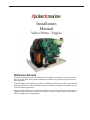
Installation
Manual
Volvo Penta - Engine
Welcome Aboard
Polar DC Generators and Volvo Penta marine engines are used all over the world today. They are used in all possible operating conditions for professional as well as leisure purposes.
Polar DC Marine is becoming a symbol of reliability, technical innovation, performance
and long service life. We also believe that this is what you demand and expect of your
Polar DC Marine generator .
Please read this operator’s manual thoroughly and consider the advice we provide on
operation and maintenance before you cast off on your voyage so that you will be ensured of fulfilling your expectations.
Installation
Marine Diesel Engines
D1-13, D1-20, D1-30
D2-40, D2-55, D2-75 Contents
Safety precautions .............................................. 2
General information ............................................ 5
Conversion factors .......................................... 7
Special tools ........................................................ 8
Installation drawings ........................................... 8
Engine installation .............................................. 9
Engine inclination ............................................ 9
Flexible shaft seal ............................................ 10
Rigid shaft seal ................................................ 10
Fitting of reverse gear and S-drive .................. 11
S-drive insulation ............................................. 11
Rubber mounts ................................................ 12
Propeller shaft system ..................................... 13
Front end power take-off ................................. 15
Cooling system ................................................ 19
Exhust system ................................................. 24
Engine room ventilation ................................... 26
Soundproofing ................................................. 28
Fuel system ..................................................... 30
Electrical system ................................................. 32
Connection of battery cables ........................... 36
Controls ................................................................ 38
S-drive installation .............................................. 41
Preparation ...................................................... 41
Cutting and fiberglassing of engine bed .......... 43
Installation of drive and engine ........................ 46
Fitting of the rubber seal .................................. 48
Installation of propeller .................................... 49
Oil quality and filling ........................................... 50
References to Service Bulletins ......................... 52
© 2007 AB VOLVO PENTA
All rights to changes or modifications reserved.
2
Printed on environmentally-friendly paper
Safety precautions
Introduction
This Installation Manual contains the information you
will need to install your Volvo Penta product correctly.
Check that you have the correct Installation Manual.
Read the Safety precautions and the General
information in the installation manual carefully
before servicing or operating the engine.
Important
The following special warning symbols are found in
this manual and on the engine.
WARNING! Danger of personal injury, damage
to property or mechanical malfunction if the instructions are not followed.
IMPORTANT! Possible damage or mechanical
malfunction in products or property.
NOTE! Important information to facilitate work processes or operation.
Below is a list of the risks that you must always be
aware of and the safety measures you must always
carry out.
Plan in advance so that you have enough room
for safe installation and (future) dismantling. Plan
the engine compartment (and other compartments such as the battery compartment) so that
all service points are accessible. Make sure it is
not possible to come into contact with rotating
components, hot surfaces or sharp edges when
servicing and inspecting the engine. Ensure that
all equipment (pump drives, compressors for example) has protective covers.
Make sure the engine is immobilized by not connecting the electrical system or turning off the
power supply to the engine at the main switch
(breakers), and locking the switch (breakers) in
the OFF position for as long as work continues.
Set up a warning notice at the engine control
point or helm.
As a rule, no work should be done on a running
engine. However, some work e. g. adjustments,
requires a running engine. Approaching an engine that is running is a safety risk. Loose clothing or long hair can fasten in rotating parts and
cause serious personal injury. If working in proximity of a running engine, careless movements
or a dropped tool can result in personal injury.
Take precautions to avoid hot surfaces (exhaust
pipes, turbochargers, charge air manifolds, starting elements etc.) and hot liquids in supply lines
and hoses in engines that are running or have
just been turned off. Reinstall all protective parts
removed during service operations before starting work on the engine.
Ensure that the warning or information decals on the product are always visible. Replace decals which are damaged or painted over.
Turbocharged engines: Never start the engine
without installing the air cleaner. The rotating
compressor turbine in the turbocharger can
cause serious personal injury. Foreign objects
entering the intake ducts can also cause mechanical damage.
Never use start spray in the air intake. Use of
such products could result in an explosion in the
air intake pipe. There is a danger of personal injury.
Do not open the filler cap for the engine coolant
(freshwater cooled engines) when the engine is
hot. Steam or hot engine coolant can be ejected
and any pressure in the system will be lost.
Open the filler cap slowly and release coolant
system pressure (freshwater cooled engines). If
the filler cap or drain cock must be opened, or if
a plug or engine coolant line must be removed
on a hot engine, steam or hot coolant can be
ejected.
Hot oil can cause burns. Avoid skin contact with
hot oil. Make sure that the oil system is released
before starting work on it. Never start or run the
engine without the oil filler cap in place because
of the risk of oil being ejected.
3
Safety precautions
If the boat is in the water, stop the engine and
close the sea cock before carrying out operations on the cooling system.
Only start the engine in an area that is well ventilated. Beware, the exhaust gas is poisonous
to breathe in. When operating in an enclosed
space, use exhaust extraction to lead the exhaust and crankcase gases away from the workplace.
Always wear protective goggles if there is a risk
of splinters, grinding sparks and splashes from
acid or other chemicals. Your eyes are extremely
sensitive and an injury to them can result in loss
of sight!
Avoid skin contact with oil! Long term or repeated skin contact with oil can lead to the loss
of natural oils from the skin. This leads to irritation, dry skin, eczema and other skin problems.
Old oil is more dangerous to your health than
new. Use protective gloves and avoid oil-soaked
clothes and rags. Wash regularly, especially
before meals. Use special skin creams to help
clean and to stop your skin drying out.
Most chemicals intended for the product (engine and reverse gear oils, glycol, gasoline and
diesel), or chemicals intended for the workshop
(degreasing agent, paints and solvents) are
harmful to your health. Read the instructions on
the packaging carefully! Always follow protective
measures (using a protective mask, goggles,
gloves etc.). Make sure that other personnel are
not unknowingly exposed to harmful substances,
in the air that they breathe for example. Ensure
good ventilation. Dispose of used and excess
chemicals as directed.
Be extremely careful when tracing leaks in the
fuel system and when testing injectors. Wear
protective goggles. The jet from an injector is
under very high pressure and fuel can penetrate
deep into tissue, causing serious injury with a
risk of blood poisoning.
All fuels and many chemicals are flammable.
Keep away from naked flames or sparks. Gasoline, some solvents and hydrogen from batteries
in the correct proportions with air are very inflammable and explosive. Do not smoke! Maintain
good ventilation and take the necessary safety
measures before welding or grinding in the vicinity. Always keep a fire extinguisher accessible in
4
the workplace.
Store oil and fuel-soaked rags and old fuel and
oil filters properly. Oil-soaked rags can ignite
spontaneously in certain circumstances. Old fuel
and oil filters are environmentally harmful and
should be sent for destruction to a proper refuse
station for environmentally harmful material for
destruction.
Ensure that the battery compartment is designed
according to current safety standards. Never
allow an open flame or electric sparks near the
battery area. Never smoke near to the batteries. The batteries give off hydrogen gas during
charging which when mixed with air can form
an explosive gas. This gas is easily ignited and
highly volatile. Incorrect connection of the battery can cause sparks sufficient to cause an
explosion with resulting damage. Do not shift the
connections when attempting to start the engine
(spark risk) and do not lean over any of the batteries.
Always ensure that the Plus (positive) and Minus
(negative) battery leads are correctly installed on
the corresponding terminal posts on the battery.
Incorrect installation can result in serious damage to the electrical equipment. Refer to the wiring diagrams.
Always use protective goggles when charging
and handling the batteries. The battery electrolyte contains extremely corrosive sulphuric acid.
If this should come in contact with the skin, immediately wash with soap and plenty of water.
If battery acid comes in contact with the eyes,
flush immediately with water and obtain medical
assistance.
Turn the engine off and turn off the power at the
main switches (breakers) before carrying out
work on the electrical system.
Clutch adjustments must be carried out with the
engine turned off.
Use the lifting eyes fitted on the engine/reverse
gear when lifting the drive unit. Always check
that the lifting equipment used is in good condition and has the load capacity to lift the engine
(engine weight including reverse gear and any
extra equipment installed).
Use an adjustable lifting beam to ensure safe lifting and avoid damage to components installed
on the top of the engine . All chains and cables
must run parallel to each other and as perpendicular as possible to the upper side of the engine.
If extra equipment is installed on the engine
which alters its center of gravity a special lifting
device is required to obtain the correct balance
for safe handling.
Safety precautions
Never carry out work on an engine suspended
on a hoist.
Never work alone when installing heavy components, even when using secure lifting equipment
such as a lockable block and tackle. Most lifting
devices require two people, one to see to the
lifting device and one to ensure that the components do not get caught and damaged.
The components in the electrical system, the
ignition system (gasoline/petrol engines) and
in the fuel system on Volvo Penta products are
designed and manufactured to minimize risks of
fire and explosion. Engines should not run in environments containing explosive media.
Always use fuels recommended by VolvoPenta.
Refer to the Owner’s Manual. Use of lower quality fuels can damage the engine. On a diesel engine poor quality fuel can cause the fuel control
rack to stick causing the engine to overspeed
with resulting risk of damage to the engine and
personal injury. Poor fuel quality can also lead to
higher maintenance costs.
5
General information
About the Installation Manual
This publication is intended as a guide for the installation of Volvo Penta D1 and D2 engines, inboard
and S-drive. The publication is not comprehensive
and does not cover every possible installation, but is
to be regarded as recommendations and guidelines
applying to Volvo Penta standards. Detailed Installation Instructions are included in most of the accessory kits.
These recommendations are the result of many years
of practical experience of installations from all over
the world. Departures from recommended procedures etc. can be necessary or desirable, however, in
which case the Volvo Penta organization will be glad
to offer assistance in finding a solution for your particular installation.
It is the sole responsibility of the installer to ensure
that the installation work is carried out in a satisfactory manner, it is operationally in good order, the approved materials and accessories are used and the
installation meets all applicable rules and regulations.
This Installation Manual has been published for
professionals and qualified personnel. It is therefore
assumed that persons using this book have basic
knowledge of marine propulsion systems and are
able to carry out related mechanical and electrical
work.
Installation of electrical systems shall only be carried
out by a professional boat electrician.
Only components, cables, connections etc, delivered
or approved by the manufacturer may be used. The
manufacturer will accept no responsibility what so
ever if this requirement is ignored.
Volvo Penta continuously upgrades its products and
reserves the right to make changes. All the information contained in this manual is based on product
data available at the time of print. Notification of
any important modifications to the product causing
changes to installation methods after this date will be
made in Service Bulletins.
6
Plan installations with care
Great care must be taken in the installation of engines and their components if they are to operate
perfectly. Always make sure that the correct specifications, drawings and any other data are available
before starting work. This will allow for correct planning and installation right from the start.
Plan the engine room so that it is easy to carry out
routine service operations involving the replacement
of components. Compare the engine Service Manual
with the original drawings showing the dimensions.
It is very important when installing engines that no
dirt or other foreign matter gets into the fuel, cooling,
intake or turbocharger systems, as this can lead to
faults or engine seizure. For this reason the systems
must be sealed. Clean supply lines and hoses before
connecting them to the engine. Only remove protective engine plugs when making a connection to an
external system.
General information
Certified engines
The manufacturer of engines certified for national
and local environmental legislation (Lake Constance
for example) pledges that this legislation is met by
both new and currently operational engines. The
product must compare with the example approved
for certification purposes. So that Volvo Penta, as a
manufacturer, can pledge that currently operational
engines meet environmental regulations, the following must be observed during installation:
•
Servicing of ignition, timing and fuel injection
systems (gasoline) or injector pumps, pump settings and injectors (diesel) must always be carried out by an authorised Volvo Penta workshop.
•
The engine must not be modified in any way except with accessories and service kits developed
for it by Volvo Penta.
•
Installation of exhaust pipes and air intake ducts
for the engine compartment (ventilation ducts)
must be carefully planned as its design may affect exhaust emissions.
•
Seals may only be broken by authorised personnel.
IMPORTANT! Use only Volvo Penta Genuine
Parts.
Using non-genuine parts will mean that AB
Volvo Penta will no longer take responsibility
for the engine meeting the certified design.
All damage and costs caused by the use of nongenuine replacement parts will not be covered
by Volvo Penta.
Seaworthiness
It is the boat builder’s duty to check that the security
requirements apply to the market in which the boat
is sold. In the USA for example, these are the US
Federal Regulations for pleasure boats described
in Title 46. The requirements described below apply
to the EU principles. For information and detailed
descriptions of the safety requirements that apply to
other markets, contact the authority for the country
concerned.
As of June 16 1998, pleasure boats and certain associated equipment marketed and used within the
EU must bear CE labels to confirm that they meet the
safety requirements stipulated by the European Parliament and Council of Europe’s directive for pleasure
boats. The normative requirements can be found in
the standards drawn up to support the directive’s
objective of uniform safety requirements for pleasure
boats in EU countries.
Certificates that grant the right for CE label use and
confirm that boats and equipment meet safety requirements are issued by approved notified bodies.
In many Member States the classification societies
have become the notified bodies for pleasure boats,
e.g. Lloyd’s Register, Bureau Veritas, Registro Italiano Navale, Germanischer Lloyd, etc.
In many cases completely new institutions have been
approved as notified bodies. The directive also allows
boat builders and component manufacturers to issue
assurances of compliance with the requirements of
the directive. This requires the manufacturer to store
the prescribed product documentation in a place that
is accessible to the monitoring authority for at least
ten years after the last product is produced.
Life boats and boats for commercial activities are approved by classification societies or by the navigation
authority for the boat’s registered country.
Joint liability
Each engine consists of many components working
together. One component deviating from its technical specification can cause a dramatic increase in
the environmental impact of an engine. It is therefore
vital that systems that can be adjusted are adjusted
properly and that Volvo Penta Genuine Parts as
used.
Certain systems e.g.components in the fuel system
may require special expertise and special test equipment. Some components are sealed at the factory for
environmental reasons. No work should be carried
out on sealed components except by authorised personnel.
Remember that most chemical products damage the
environment if used incorrectly. Volvo Penta recommends the use of biodegradable degreasing agents
for cleaning engine components, unless otherwise
indicated in a Workshop Manual. Take special care
when working on board boats to ensure that oil and
waste are taken for destruction and not accidentally
pumped into the environment with bilgewater.
7
General information
Conversion factors
Metric to U.S. or IMP. conversion factors:
U.S. or IMP. to metric conversion factors:
To convert from To Multiply by To convert
from To Multiply by
cm inch inch cm 2.540
Area mm² sq.in. 0.00155 sq. in. mm² cu. in. 0.06102 cu. in. cm³ cu. in. 61.023 cu. in. litre, dm³ 0.01639
litre, dm³ 3.785
Length mm m
cu. ft. litre, dm³ imp. gallon litre, dm³ Force 3.2808 litre, dm³ foot sq. ft. cm³
0.03937 m² Volume inch litre, dm³ m³ N
0.3937 10.76 0.03531 0.220 U.S. gallon 0.2642 lbf 0.2248 cu. ft. 35.315 Weight kg lb. kW bhp 1.341 lbf ft 0.738 Power kW kW Torque Nm MPa Pa psi mm Wc KPa mWg psi MJ/kg BTU/lb kJ/kg Fuel g/kWh consump. g/kWh Inertia kgm² Flow, gas m³/h Flow, liquid m³/h Speed Temp. m/s mph
145.038 0.102 0.004 4.0 in Wc BTU/hph 14.5038 in Wc kJ/kWh kJ/kg 56.87 in Wc Energy Work 1.36 BTU/min Pressure Bar Pa 2.205 hp (metric) 1) 39.37 0.697 BTU/lb kcal/kg g/hph lb/hph lbft² 0.430 430 0.736 0.00162 cu.ft./min. US gal/min ft./s knots
23.734 0.5886 4.403 3.281 0.869
°F=9/5 x °C+32 1) All hp figures stated in the catalogue are metric.
8
0.239 inch foot sq. ft. cu. ft. imp. gallon U.S. gallon cu.ft. lbf lb. mm m
0.3048
m² 0.093
litre, dm³ litre, dm³ m³ N
kg hp (metric) 1) kW BTU/min kW bhp lbf ft 4.545
0.0283
4.448
0.454
0.735
1.356
Pa in Wc 28.320
Nm mm Wc in Wc 16.388
0.7457
Bar in Wc 645.2
kW psi psi 25.40
MPa Pa KPa mWg 0.0176
0.06895
0.006895
9.807
249.098
0.24908
0.0254
BTU/hph kJ/kWh BTU/lb MJ/kg 0.00233
g/hph lb/hph g/kWh g/kWh 1.36
616.78
BTU/lb kcal/kg kJ/kg kJ/kg lbft² kgm² US gal/min m³/h cu.ft./min. ft./s knots
°C=5/9 x (°F–32)
m³/h m/s mph
1.435
2.326
4.184
0.042
1.699
0.2271
0.3048
1.1508
Special tools
Engine bed tool
Engine bed tool for D1-series and D2-series can be
produced locally. Contact Volvo Penta organisation
for drawings of a suitable tool.
Installation drawings
Installation drawings regarding the D1 and D2 engines are available at:
http://www.volvopenta.com.
9
Engine installation
Engine inclination
Flywheel down
Flywheel up
Max. inclination
StaticUnder way
Flywheel
Flywheel
Sideways
Engine
down
up
down
up
D1-ser.
15°
0°
25°
0°
35°
D2-40
15°
0°
25°
0°
35°
D2-55/75
15°
0°
35°
10°
35°
Service accessability
When you design the engine installation,
always pay attention to the access needed
for correct engine service. Also ensure that
the complete engine can be removed without
damage to the boat structure.
There must also be sufficient space for the
sound proofing material.
NOTE! See installation drawing for space required to lift out engine.
NOTE! Minimum recommended access two
sides, front and starboard.
10
Engine Instillation
Flexible shaft seal
Volvo ´Penta water lubricated rubber type
Max. 1500 mm (59")
Grease lubricated shaft seal
Max. 1800 mm (71")
When using a flexible shaft seal and flexible engine
suspension, a flexible shaft coupling must not be fitted.
Rigid shaft seal
Flexible shaft
coupling
Rigid
shaft seal
When using a rigid shaft seal and flexible engine suspension, a flexible shaft coupling must be fitted.
11
Engine installation
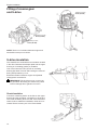
Fitting of reverse gear
and S-drive
Tightening torque:
40 Nm (29 ft/lb)
Tightening torque:
40 Nm (29 ft/lb)
Tightening torque:
40 Nm (29 ft/lb)
NOTE! There is no insulation between engine and
transmission except on S-drives.
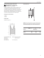
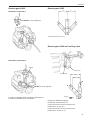
S-drive insulation
The 130S/SR and 150S/SR has an insulation located
in the drive. Between the adapter plate and the upper
housing is a insulating gasket (C) installed.
One of the lower two bolts (A) has an insolating
bushing (B) fitted. This bolt and bushing are secured
during transportation by a nut.
Electrical insulation between engine and flywheel
casing/power transmission.
IMPORTANT! The S-drive must on no account
be grounded. Grounding the S-drive may cause
serious damage due to galvanic corrosion.
Check insulation
Connect a measuring device to the bolt on the upper
housing and the grounding connection on the engine.
The result should be above 100 kW. If the measured
value is below 100kW the installation needs to be reviewed. Please contact your Volvo Penta dealer.
12
C
Engine Instillation
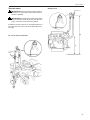
Rubber mounts
70 Nm (52 lb.ft)
A
A
70Nm (52 lb.ft)
D1-20 and D1-30, Inboard
Tightening torque
Tightening torque, rubber mounts,
all D1 and D2 engines: 70 Nm (52 lb.ft)
A
A- measurement, D1 and D2
Unloaded conditions
TransmissionFront
mm (")
Rear
mm (")
Reverse gear
85±8 (3.3±0.3)
85±8 (3.3±0.3)
S-driveFixed Fixed
NOTE! Make sure that the rubber mounts are installed so that no pre-load or side forces occur when
the engine has been installed and aligned with the
propeller shaft.
Compare front and rear mounts sidewise in pairs.
Adjust if necessary.
13
Engine installation
Propeller shaft system
Dimensions
Engine Reverse gear ratio Shaft diameter, min. mm
(")*
D1-13
2.4:1–2.7:1
Æ=25 (1.0)
D1-20
2.4:1–2.7:1
Æ=25 (1.0)
D1-30
2.4:1–2.7:1–2.6:1
Æ=25 (1.0)
D2-40
2.1:1–2.6:1
Æ=30 (1.2)
D2-55
2.2:1–2.7:1
Æ=30 (1.2)
D2-75
2.1:1–2.3:1
Æ=30 (1.2)
D2-75
2.4:1–2.8:1
Æ=35 (1.4)
* With Volvo Penta standard material
Propeller shaft coupling
Reverse gear flange
Transmission
mm (inch)
D
Pcd
d
MS10 A/L
102 (4.02)
80 (3.15)
60 (2.36) H8 12 (0.47) 3.5 (0.14)
4x11.5 (0.45)
MS15 A/L
102 (4.02)
80 (3.15)
60 (2.36) H8 12 (0.47) 3.5 (0.14)
4x11.5 (0.45)
MS25 A/L
102 (4.02)
80 (3.15)
60 (2.36) H8 12 (0.47) 3.5 (0.14)
4x11.5 (0.45)
HS25A
127 (5.00)
108 (4.25) 63.5 (2.50) H8
* Female configuration
14
T
A
10 (0.39)
N x Hd
–4* (–0.16)* 4x11.5 (0.45)
Engine Instillation
Reverse gear ratios
Reverse gear Ratio RH
Alignment
Ratio LH
MS10L2.35:12.26:1
Before the propeller shaft is connected to the reverse
gear flange, check to make sure that the flanges are
parallel.
A
MS10L2.72:12.26:1
MS10A2.35:12.70:1
MS10A2.72:12.70:1
MS15L2.14:11.95:1
MS15L2.63:11.95:1
MS15A2.14:11.95:1
MS15A2.63:11.95:1
MS25L2.27:12.10:1
MS25L2.74:12.72:1
MS25A2.23:12.74:1
MS25A2.74:12.74:1
HS25A2.29:12.29:1
HS25A2.71:12.71:1
130S/SR
2.19:1
2.19:1
150S/SR
2.19:1
2.19:1
Move the flanges together so that the guide engages.
Then, with the flanges pressed together, check that
they are parallel and that a 0.10 mm (0.004") feeler
gauge cannot be inserted anywhere inbetween them
(A).
Then turn the flanges 90°, 180° and 270° and repeat
this check at the new positions. Make sure that the
flanges are well pressed together during the entire
check. If the deviation is greater than 0.10 mm
(0.004"), the alignment must be re adjusted.
Remove any aids being used and connect the shaft
to the reverse gear flange, or flexible coupling.
IMPORTANT! The alignment should be rechecked again a few days after the launch when
the boat is completed (extra critical with sailboats).
15
Engine installation
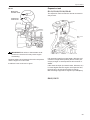
Front end power take-off
IMPORTANT! D1-13 engines only:
Power take-off is not allowed.
Front mounted universal bracket
This universal bracket, with adjustable attachments,
allows air conditioning compressors or hydraulic
pumps etc. to be installed and operated. The kit contains the bracket and fittings.
The table below shows the width and length of the
mounting plate.
L
Top mounted extra alternator
Added installaltion length (A): 82 mm (3.2")
Added installaltion width (B): 18 mm (0.7")
W
Engine
Width,
Lenght,
W mm (")
L mm (")
D1, D2-40
582 (22.9)
140 (5.5)
D2-55, D2-75
634 (25.0)
170 (6.7)
A
The increase in length of the engine installation
depends on how the bracket is installed. Auxiliary
equipment can increase the length further.
NOTE! Additional rear brackets are required when
installing a universal bracket on a S-drive engine .
Rear brackets are included in a separate kit.
B
16
Engine Instillation
Extra pulleys (power take-off)
D2-55 and D2-75
IMPORTANT! D1-13 engines only:
Power take-off is not allowed.
Auxilliary equipment driven by the drive belt on the
crankshaft of the engine increase the load on the
crankshaft. Therefore it is important to review the position and power requirement of the power take-off.
2
Maximum power supplied depends on the alignment
of the belt, the belt type and the engine type.
Pulley groove alternatives:
- HC50
- Multi-V
3
Pulley HC50
1
Number of groves: 1
NOTE! The following table only gives general advice
about the power which can be taken via a maximum
of three extra belt grooves on the crankshaft nose.
W
B
Pulley
1 2 3
EnginekW/pulley*
D
Overall diameter (D)
6.8
6.8
6.8
D2-75
6.8
6.8
6.8
120+0.5 mm (4.72+0.02")
Width (W)
(0.71±0.01")
Belt width (B)
D2-55
18.0±0.25 mm
12.7 mm (0.50")
17
Engine installation
D1-20, D1-30 and D2-40
NOTE! The maximum permissable torque shown in
the figures can be applied for one pulley at a maximum distance from the cylinder block corresponding
to 4 pulleys or 3 spacers and one pulley. If several
pulleys are to be used the permissable torque has
to be divided so that torque limitations are not exceeded.
D1-20
Permissible torque
a°Nm
0°13.2
30°11.8
60°7.7
90°6.0
120°5.6
150°6.4
180°8.6
210°13.2
240°13.2
270°13.2
300°13.2
330°13.2
D1-30
Permissible torque
a°Nm
0°18.0
30°12.9
60°9.4
90°7.8
120°7.5
150°8.7
180°11.0
210°14.7
240°21.1
270°24.0
300°24.6
330°24.1
D2-40
Permissible torque
a°Nm
0°21.7
30°21.7
60°21.7
90°21.2
120°20.8
150°21.7
180°21.7
210°21.7
240°21.7
270°21.7
300°21.7
330°21.7
18
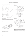
Engine Instillation
Example - D1-30 - One pulley used
The engine is a D1-30 and the direction of force for
two auxiliaries is A=10° and B=120°.
Maximum permissible torque for auxiliary A and B
depends on the vector sum of their directions of force
and their torque. The combination must end up within
the permissible torque range.
In this example, the torque for the auxiliary is A=10
Nm (7.4 lbf ft) and B=4 Nm (3.0 lbf ft).
The resultant force gives a torque C=10.1 Nm (7.4 lbf
ft) with direction of force 32.9°. The resultant ends up
within the permissible torque.
In every case:
Read off the resultant of two torques with different
directions of force by drawing a parallelogram in the
graph on the same principles as in the example.
B
A
19
Engine installation
Cooling system
Seawater intake
100–200 mm
(4–8")
WL
Seawater filter
Internal hose diameter:
MS10,15 19 mm (3/4")
MS25, HS25 32 mm (1 1/4")
130S
19 mm (3/4")
150S
32 mm (1 1/4")
Always install a shut-off valve on the water intake.
Two hose clamps for each connection should be
used.
Seawater inlet
If a scoop pickup is used on a sailing boat the water
intake should be facing backwards to avoid water to
be pushed into the exhaust system during sailing.
20
The seawater filter should be installed minimum 100
mm and maximum 200 mm (4–8") above the static
water line level.
NOTE! At all load conditions.
IMPORTANT! No valves or connections that
could restrict water flow may be installed in the
cooling system.
Engine Instillation
Vacuum valve
IMPORTANT! Vacuum valves require service.
Therefore, do not install a valve unless below
criteria is fullfilled.
D2-55, D2-75
Æ 25 mm (1")
IMPORTANT! If the distance from static water
level to exhaust outlet (A) is less than 200 mm
(7.9") a vacuum valve must be installed.
Install the vacuum valve in an accessible place not
less than 500 mm (19.6") above loaded water line
level (B).
D1-13, D1-20, D1-30, D2-40
Æ 19 mm
(3/4")
21
Engine installation
Hot water circuit
D2-55
NOTE! Maximum external circuit volume:
Outlet to hot
water circuit
D1-13, D1-20, D-30, D2-40
3.0 l (3.2 US qts)
D2-55, D75
1.6 l (1.7 US
qts)
Larger volumes require additional expansion tank.
NOTE! All hose connections for hot water outlets are
intended for a hose inner diameter of 16 mm (5/8").
The hoses should be bent in gentle curves and in a
way which avoids them being pinched or kinked.
D1-13, D1-20, D1-30, D2-40
Outlet to
hot water circuit
Thread 3/8" -18 NPTF
Return from
hot water circuit
Thread 3/8" -18 NPTF
Thread 3/8" -18 NPTF
Return from hot
water circuit
Thread 3/8" -18 NPTF
Thread 3/8" -18 NPTF
The upper edge of the hot water heater should be
placed min. 50 mm (2") below the engine’s expansion tank.
If expansion tank kit is mounted, the upper edge of
hot water heater should not be placed higher than
the ”MIN” marking on the expansion tank.
The upper edge of the hot water heater should be
placed min. 50 mm (2") below the engine’s expansion tank.
If expansion tank kit is mounted, the upper edge of
hot water heater should not be placed higher than
the ”MIN” marking on the expansion tank.
22
Engine Instillation
D2-75
Return from
hot water circuit
Expansion tank
D1-13, D1-20, D1-30, D2-40
The expansion tank can also be remote mounted for
easy access.
Outlet to hot
water circuit
Æ 7.5 mm
(0.3")
Æ 16 mm
(5/8")
Max 1.2 m
(4 ft)
IMPORTANT! No valves or thermostats are allowed in the circuit as this may cause engine
overheating.
Replace existing hose between the turbo compressor
and the engine oil cooler outlet.
Install two hoses as shown in figure.
If an external cirquit (hot water heater, defroster, etc)
containes a larger water quantity than 3.0 liters (3.2
US qts) a larger or extra expansion tank must be installed.
If the external cirquit (hot water heater, defroster, etc)
is routed higher than the engine the expansion tank,
the tank has to be moved according to figures.
Max mounting height above engine top: 1.2 m (4 ft ).
D2-55, D2-75
23
Engine installation
The loose standard expansion tank must be bulkhead mounted.
If an external cirquit (hot water heater, defroster, etc)
Max 1.2 m
(4 ft)
containes a larger water quantity than 1.6 liters (1.7
US qts) or the cirquit is routed higher than the engine
a larger or extra expansion tank must be installed.
If the external cirquit (hot water heater, defroster, etc)
is routed higher than the engine the expansion tank,
the tank has to be moved according to figures.
Max mounting height above engine top: 1.2 m (4 ft ).
24
Engine Instillation
Exhaust system
Routing of exhaust hose between
silencer and exhaust bend
A
H
Min.
100 mm
(4")
Min. 350 mm above water level
in loaded conditions
IMPORTANT! Residual water must flow to silencer or overboard when the engine is shut off.
Highest position of silencer in relation to
exhaust hose length, all engines
mm (inch)
A
H
300 (11.8)
110 (4.3)
400 (15.7)
120 (4.7)
600 (23.6)
150 (6.0)
1300 (51.2)*
180 (7.1)
*) Support needed to avoid water to stay in hose before silencer.
IMPORTANT! If measurement H cannot be met,
an exhaust riser has to be installed.
25
Engine installation
Exhaust hose dimensions
Exhaust riser
D1-13, D1-20, D1-30, D2-40
Exhaust riser
B
Engine
Hose inner diameter mm(")
D1-series
45 mm (1 3/4)
D2-40
45 mm (1 3/4)
D2-55
57 mm (2 1/4)
D2-75
90 mm (3 1/2)
Exhaust back pressure measurements,
kPa, (psi / mm Wc)
EngineBack pressure
Minimum
Maximum
Standard installation
Engine
B measurement, mm (")
D1-13197 (7.75)
D1-20197 (7.75)
D1-30222 (8.75)
D2-40222 (8.75)
Exhaust riser installation
Engine
B measurement, mm (")
D1-13288 (11.3)
D1-20288 (11.3)
D1-30323 (12.7)
D2-40323 (12.7)
The riser increases the overall engine installation
height by 12 mm (0.5").
26
D1-series
—
D2-40
—
D2-55
15 (2.2/1530)
D2-75
15 (2.2/1530)
20 (2.9/2040)
20 (2.9/2040)
20 (2.9/2040)
20 (2.9/2040)
Engine Instillation
Engine room ventilation
Engine air consumption
The engine consumes a certain amount of air in the
combustion process. This requires a minimum internal area in the air supply ducting.
The area can be calculated by using the formula:
A = 1.9 × engine power output
A = Area in cm²
Engine output in kW
The value applies for non-restricted intake and up to
1 m (3.3 ft) duct length with only one 90 degree bend.
The bending radius should be at least twice the diameter.
Two main conditions must be met:
1. The engine must receive enough air (oxygen) for
combustion of the fuel.
2. The engine room must be ventilated, so that the
temperature can be kept down to an acceptable
level.
Ventilation is also important to keep the engine’s
electrical equipment and fuel system at a low temperature, and to ensure general cooling of the engine.
NOTE! All valid safety regulations and legal requirements for each country must be followed. Each classification society has its own regulations that must be
followed when required.
The temperature of the inlet air at the air filters must
not be higher than +25°C (77°F) for full power output.
During sea trials the air temperature in the air filter
should not exceed 20°C (36° F) above ambient temperature.
If longer ducts or more bends are used, the area
should be corrected by multiplying by a coefficient
from Table 1 below.
Number Duct length, m (ft)
of bends 1 (3.3)
5 (16.4)
2 (6.6) 3 (9.8) 4 (13.1)
1
11.04 1.09 1.13
1.20
2
1.391.41 1.43 1.45
1.49
3
– 1.70
1.78
1.72
1.74
Table 1.
The temperature of the engine itself is rather high in
some places. Certain separate electric components,
such as charging regulators and relays, should therefore be fitted on bulkheads or elsewhere where the
temperature is relatively low.
The maximum temperature for areas where electric
components are fitted is 70°C (158°F). The starter
motor and alternator however, have their given locations.
NOTE! The total intake area can be calculated by using the formula:
Total intake area = Engine air consumption + Engine room ventilation
Area in cm²
27
Engine installation
Engine room ventilation
A great deal of the radiant heat must be transported
out of the engine room to keep the engine room temperature down to the permitted values, in other words
the heat must be ventilated away .
The same dimension must be chosen for the inlet
and outlet ducts to achieve low flow speeds and low
noise levels.
The area of the inlet/outlet air supply is calculated using the formula:
Inlet air
= 1.65 × engine power output
Outlet air = 1.65 × engine power output
Areas in cm²
Engine power output in kW.
These values must be corrected according to Table 1
with regard to bends and duct length.
The ambient air temperature (outdoor air temperature) is assumed to be +30°C (86°F). Correction factors as per Table 2 shall be used where applicable.
Ambient air temperature °C (°F)
Correction factor
+20 (68) 0.7
+30 (86) 1.0
+40 (104) 1.4
Table 2.
28
Fan selection
The fan must be dimensioned according to air flow
volumes as follows:
Air flow = 0.07 × engine power output
Air flow volume in m3 /min
Engine power output in kW.
The total pressure increase across the fan should be
10 mm (0.39") water column (100 pa).
These two values, flow and total pressure increase,
are sufficient for the selection of a fan. If the fan is fitted directly to the bulkhead, i. e. without a connection
pipe, the value of the total pressure increase can be
reduced to 7 mm (0.28") water column (70 pa). This
means that a somewhat smaller fan can be used.
Engine Instillation
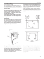
Soundproofing
The greatest possible care must be given to the task
of screening the sound source as well as possible.
Screen all the way down to the hull but leave a small
distance to prevent bilgewater from penetrating the
insulation material.
Structural noise
Cracks, openings etc. must be carefully sealed off
with insulation material. In cases where the engine is
installed under the floor, line all bulkheads and floorboards.
The drive package must be installed in such a way
as to minimize noise and vibration. The noise that occurs is airborne noise and structural noise (vibration).
Vibration from the engine is transmitted via the engine mountings and the engine bed to the hull. Other
routes are via the transmission and propeller systems, exhaust pipe, coolant pipes, fuel pipes, electrical cables and control cables.
Pressure pulses from the propeller are transmitted
through the water and into the hull. Pulsating thrust
from the propeller enters the hull via support blocks,
bearings and seals.
Airborne noise
This section refers to airborne noise from the engine
bay. The most important measure to lower airborne
noise from the engine room is to seal the room properly. Further improvements in noise level reduction
can be achieved by sound insulation material and by
designing sound traps for the air inlets.
The engine installation should be soundproofed in order to obtain a noise level that is as low as possible.
Build the engine compartment with sound traps. Various types of sound traps can be selected. The figure
shows a type that is also provided with drainage.
Furthermore, due consideration must be given to the
thickness of the insulation material.
Prior to installing the insulation material, make sure
that there is sufficient room for checking, service and
repair and for engine movements during operation.
Also make sure that all hatches are properly sealed.
Make sure the necessary room is available for service and repair. Also make sure that all hatches are
properly sealed.
29
Engine installation
Insulation material installed on wood (plywood):
1. Wood (plywood)
2. Flame-proof absorption sheeting.
3. Flame-proof, reflecting soundproofing foil.
Above you can see an example of the construction of
an insulation material. This type of insulation material
is glued to the frame.
NOTE! The insulation sheeting faces differently, owing to the type of the material in the frame, i.e. GRP
or wood.
Insulation material, being applied on wood (plywood):
Fuel hoses going through a bulkhead should be protected by a grommet where they pass through the
bulkhead. The grommet seals off and protects the
hose against sharp edges, which might cause leakage.
Other cables, electrical wires, battery leads etc can
be drawn through a rubber hose or through a special
PVC-tube (electrical conduit), built onto the GRP
bulkhead of GRP. Any gaps between the tubing and
the wires can be sealed off with some kind of insulation material or sealing compound.
Insulation material installed on GRP:
1.GRP
2. Iron-PVC, thickness 2.5 mm (0.1")
3. Flame-proof absorption sheeting
4. Flame-proof, reflecting soundproofing foil
Shift cables, throttle cables and electrical wires
coming through bulkheads can preferably be drawn
through a tube or a grommet, sealing off properly. At
the same time the cables are protected against wear.
30
Engine Instillation
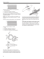
Fuel system
Piping
All fuel lines should be installed and properly
clamped near the bottom of the boat to avoid heat
absorption. The air temperature is lower at the bottom of the engine room.
Rubber hoses
Clamp the fuel line. Distance between clamps approx. 300 mm (12").
Make sure the hose cannot be damaged by sharp
edges.
NOTE! Legal requirements may demand fuel shut-off
valve on return line.
Inner diameter
Required minimum inner diameter for
feed line hose: 10 mm (3/8").
return hose: 10 mm (3/8").
NOTE! Only use approved flexible hose.
Inner diameter
10 mm (3/8")
Connections
Min. inner diameter: 7.0 mm (0.28")
Male thread : 1/4" NPTF
Volvo Penta part no.: 3825000
31
Engine installation
Steel and copper piping
Outer diameter
Clamp the fuel line. Distance between clamps approx. 300 mm (12").
When steel and copper pipes are used there must
be a flexible connection (hose) between the pipe and
the engine.
Required minimum outer diameter for
feed line pipe: 10 mm (3/8")
alt. 12 mm (1/2").
return pipe: 10 mm (3/8")
The figure shows a transition from flexible fuel hoses
(1) to steel or copper pipes (2).
NOTE! Legal requirements may demand fuel shut-off
valve on return line.
Inner diameter
10 mm (3/8")
A
Outer diameter
10 mm (3/8")
3/4"-16UNF
1/4"-18NPTF
2
1
Fuel pre-filter
Connections
Min. inner diameter: 7.0 mm (0.28")
Male thread : 1/4" NPTF
Volvo Penta part no.: 3825000
Use a fuel pre-filter of correct size to avoid excessive
resistance across the filter. The recommended filtration is 10 micron (10m) .
NOTE! Fuel pre-filters with a glass bowl may not be
installed in boats intended to be CE-marked.
32
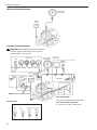
Electrical system
MDI
The MDI is located at the engine and is connected to
a number of nearby components, such as sensors,
control panel and instruments.
A data link (CAN bus) links the MDI to the tachometer/display and other optional equipment such as
NMEA2000 interface and multisensor.
Fuel tank
Aux input alarm
Preheat
Button panel
IMPORTANT! Note connection of engine harness to MDI.
Battery +
Multilink
Start
Engine harness
Control panel
A. On/Off button
Press this button to engage or turn off the system.
NOTE! The control panel must not be turned off while
the engine is running.
A
D
B. Multifunction button
- Alarm acknowledgement
- Dimmer (background lighting)
- Contrast (tachometer LCD)
C. Stop button
The engine stop running when this button is
pressed.
B
C
D. Start button
When this button is pressed the glow function is
activated and the starter is engaged.
33
Engine installation
Minimum instrumentation
EVC system
tachometer
4
Button
panel
1
1
MDI
Optional instrumentation
IMPORTANT! The MDI system allows maximum
one EVC system tachometer and/or one EVC
system display in the system.
EVC system
tachometer
Instruments
ADU
EVC system display
NMEA
Interface
4
2
Aux relay
Buzzer
To
To
neutral power
switch switch
Multisensor
1
7
NOTE! Jumpers are mounted.
3
Power switch
3
Aux
switch
input
For example a bilge water level switch
Switch logics
Neutral switch
MDI
Fuel
level
sender
Aux switch input:
1
34
5
8
3
3
3
5
5
Button
panel
3
Fuel level sender resistance:
3 - 180 ohms, 3 ohm = empty tank
Secondary helm station
IMPORTANT! The MDI system allows maximum
one EVC system tachometer and/or one EVC
system display in the system.
EVC system
tachometer
Instruments
ADU
NMEA
Interface
2
Aux relay
4
Multisensor
5
5
5
8
Main helm station
Neutral
switch
Power
switch
Button
panel
1
MDI
Aux
switch
input
Fuel
level
sender
1
Buzzer
6
3
3
1
7
Secondary helm station
1
Button
panel
EVC system display
Neutral
switch
Buzzer
IMPORTANT! Only one neutral switch and power switch input shall be installed to the MDI. The
neutral switch function shall be routed in serial to
both helm stations/controls for full functionality.
IMPORTANT! The cable for neutral switch,
power switch and buzzer shall be interconnected
between the Y-connector and engine, at main
helm station.
NOTE! Jumpers are
mounted. Neutral switch
and power switch shall
not be used. Only buzzer on secondary helm
station.
35
Electrical system
Cables and cable harnesses
Pos. in figure
m
ft
1. Extension cable, 6-pin
1.5
3.0
5.0
7.0
9.0
11.0
5
10
16
23
30
36
2. Extension cable, 3-pin
For Easylink instruments (gauges)
1.5
3.0
5
10
3. Connection cable, 2-pin
10.0
32
4. Tachometer cable, 6-pin
For tachometer and multilink
1.5
5
5. Y-split, multilink, 6-pin
6. Y-connector, 6-pin (P/N 874760)
7. Cable harness
For neutral switch, power switch and buzzer
8. Auxiliary relay cable
IMPORTANT! Never use any kind of grease in
the EVC connectors.
36
IMPORTANT! Never cut or modify the Volvo
Penta EVC cable harnesses.
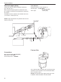
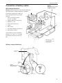
Electrical system
Connection of battery cables
NOTE!
Max tightening torque:
10 Nm (7.4 lb.ft)
With charge distributor
NOTE! Remove the 25 mm² cable between alternator
and starter when a charge distributor is installed.
Connection of diod/sensor cable system to standard alternator, principle
drawing
1. Sensor conductor (yellow,
1.5 mm2, 16 AWG)
3
S
4
B+
2. Charge distributor (accessory)
1
B–
3. Alternator, 115 A
6
4. Fuse panel (accessory)
5. Starter
2
6. Main switch
7. Accessory batteries (accessory)
+
8. Start battery (engine)
+
Another battery may be installed in
parallel (+ to + and – to– ) to obtain
more battery capacity for accessories.
5
5
–
–
8
7
+ cable
– cable
Without charge distributor
Cable area
25 mm2
From
alternator
(+)
NOTE!
Max. tightening torque:
10 Nm (7.4 lb.ft)
Main
switch
Starter
(+)
From
battery (+)
From
battery (+)
Engine
block (–)
37
Electrical system
Total cable length and cable area, battery to starter
For cables that carry starting current, for systems with and without charge distributor.
Cable length in meter (ft)
–1.3 (–4.2)
1.3–1.8
(4.2–5.9)
1.8–2.6
(5.9–8.5)
2.6–3.7
3.7–4.8
(8.5–12.1) (12.1–15.7)
Cable area in mm2 (min)
EngineD1
D2
2535
35 35
50
50
70
70
95
95
Total power cable length and cable area, alternator–battery
For cables that carry charging current, for systems with charge distributor.
Cable length in meter (ft)
–2.5 (8.2)
Cable area in mm2 (min)
Engine D1, D2
2535
2.5–3.5 (8.2–11.5)
3.5–5.0 (11.5–16.4) 5.0–7.0 (16.4–23.0)
50
70
Main switch requirements
Normal
voltage
Nominal capacity
Contin-
During During
uous
5 sec.
<48V 150A 1000A 450A
Relation between mm²
(sq in) and AWG
AWG
in
mm² (std.)
180.75
161.5
142.5
122.5
10
6
810
610
516
425
325
235
1/0
50
AWG = American Wire Gauge
38
sq.
0.029
0.044
0.098
0.098
0.236
0.393
0.393
0.629
0.984
0.984
1.378
1.969
Working temp.
5.5 min. Max.
+ 85°C
+185°F
Standard
degree
Protection
SAE J1171
IP 66
Marine
Recommended start battery capacity
Engine
Ah
CCA
SAE standard
D170540
D288700
CCA = Cold Cranking Amp.
Controls
Connecting the
speed control cable
IMPORTANT!
To be counter
locked.
Connecting the
gear shift cable
IMPORTANT! The gear shift cable routing is
very important for control functionality. The shift
cable must attach to the reverse gear lever in a
straight and unstrained way.
Sail boat drive 130S/SR, 150S/SR
FORWARD position, left hand rotating propeller
Left-hand propeller
Standard recommendation is propeller
with left hand rotation for forward.
39
Controls
Reverse gear MS10, MS15, MS25
REVERSE
position
FORWARD
position, right
hand rotating
propeller
From astern
Right-hand propeller
Standard recommendation is propeller with right
hand rotation for forward.
The bracket may be turned 90° for cable installation
from above.
From port side
A
The bracket can be mounted for cable installation
from astern and from port side.
A = 25–30 mm (1.0–1.2")
40
A
Controls
Reverse gear HS25
Reverse gear HS25
Alternative connection 1
A
A
NOTE! Loose fit required.
A = 30–35 mm (1.2–1.4")
Reverse gear HS25 with trolling valve
Alternative connection 2
Bracket
Trolling lever
Shifting lever
51 (2)
44 (1.7)
B
NOTE! Loose fit required.
In order to install the cable according to alternative 2,
a bracket is available as an accessorie.
A
Engine
Position A: Maximum slipping
Position B: Trolling fuction off
Lever travel for the outer pivot point from
position B–A: 51 mm (2")
Lever travel for the inner pivot point from
position B–A: 44 mm (1.7")
41
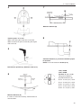
S-drive installation
Preparations step 1–8
1
3
Alternative 1
800 (31.4)
100 (3.9)
115
(4.5)
310 (12.2)
230 (9.0)
Engine mounting
Alternative 2
665–690
(26.1–27.1)
The engine may be installed with the flywheel facing
forward or backwards.
2
100 (3.9)
115
(4.5)
230 (9.0)
454–480
(17.9–18.9)
Necessary space for drive to be installed/taken
out.
Adjust the boat so the expected waterline is horizontal both length – and sidewise
42
NOTE! Make sure it is enough space to mount and
dismount the drive for future maintenance and repair.
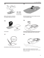
S - drive installation
4
7
B
Drilled hole,
position (a)
295 mm (11.6")
Measure distance (B).
Position point "a" in hull
Make a line along the center line of the boat.
8
C
Make sure there is space for bonding the engine
bed to the hull.
5
Calculate distance (C), clearence between propeller and hull.
NOTE! C must be minimum 20 mm (0.8").
Drill ahole in position (a), diameter 8 mm (0.3")
130S, 130SR
150S, 150SR
6
Formula: C = D – A + B
425 mm
(16.7")
Approx. 5
mm (0.2")
300 mm
(11.8")
D
This gives at different
propeller diameters (D):
D=18" C=140 (5.5") –A+B
D=19" C=128 (5.0") –A+B
D=20" C=115 (4.5") –A+B
A
D=21" C=103 (4.0") –A+B
D=22" C= 91 (3.6") –A+B
Measure distance (A)
In order to cut the bed correctly, measurement A
must be taken.
43
S-drive installation
Cutting and fiberglassing of
engine bed, step 9–23
12
9
Cut the bed according to this line.
Put the bed in its position and align it so it is horisontal.
13
10
Min. 40 mm
(1.6")
Make a marking on the bed according to figure
above.
NOTE! Recommended distance: 40 mm (1.6").
11
Adjust a pair of compasses to the distance between the hull and the marking made at fig. 10.
Make a line around the complete bed at this height.
44
Grind off the gelcoat on the surface of the bed
where there will be covered with fibre glass.
14
Put the bed back in the hull, position it correctly
and make a marking around it.
S - drive installation
15
18
130S, 130SR
150S, 150SR
A= 125 (4.92")
B= 62.5 (2.46")
Mark up the position of the hole
according to dimensions above.
16
Grind off the gelcoat on the hull where it will be
covered with fibre glass.
19
Cut the hole.
Protect the surface of the bed where the mounts
and clamp ring/diaphragm will be positioned.
17
20
Smoothen the corner off the inside of the hull.
Make sure the bed is positioned correctly.
Make a few markings to make sure it does not move
during the bonding.
45
S-drive installation
21
23
Fibre glass the bed to the hull.
Drill a drain hole, diameter approximately 30 mm
(1.2").
Clean off the extra fiberglass.
22
Protect the surface with top coat.
46
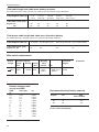
S - drive installation
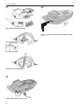
Installation alternative A.
Drive and engine as one unit
3
1
A
20 Nm
(15 lb.ft)
40 Nm
(30 lb.ft)
20 Nm
(15 lb.ft)
Tighten the clamp ring to the bed.
NOTE! Use no chemicals like grease, silicon etc. on
the diaphragm.
Tighten the rear mount to the clamp ring.
Install the S-drive to the engine.
Lift the engine and the drive onto the boat.
WARNING! Always use both lifting eyes when
lifting the engine.
A
2
NOTE! D2-55, D2-75 only: Mount distance plate (A).
4
70 Nm
(52 lb.ft)
D2-55
D2-75
Put the clamp ring on top of the diaphragm.
Install the engine and S-drive.
40 Nm
(30 lb.ft)
Install the front mounts.
NOTE! D2-55 and D2-75 has two washers between
mount and engine bracket.
47
S-drive installation
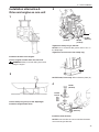
Installation alternative B.
Drive and engine separated
4
1
A
20 Nm
(15 lb.ft)
Put the clamp ring on top of the diaphragm.
40 Nm
(30 lb.ft)
20 Nm
(15 lb.ft)
NOTE! D2-55, D2-75 only: Mount distance plate (A).
2
A
Connect the engine to the S-drive.
5
Put the S-drive through the hull.
Water resistant grease,
Volvo Penta part no. 828250
3
20 Nm
(15 lb.ft)
Tighten the clamp ring to the bed.
NOTE! Use no chemicals like grease, silicon etc. on
the diaphragm.
Tighten the rear mount to the engine bed.
NOTE! Apply water resistant grease on output shaft
splines.
WARNING! Always use both lifting eyes when
lifting the engine.
Tighten the S-drive to the engine.
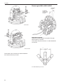
48
S - drive installation
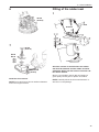
6
Fitting of the rubber seal
1
40 Nm
(30 lb.ft)
Acetone
7
Glue
70 Nm
(52 lb.ft)
D2-55
D2-75
40 Nm
(30 lb.ft)
Install the front mounts.
NOTE! D2-55 and D2-75 has two washers between
mount and engine bracket.
Grind the surface of the hull where the rubber
seal shall be attached and the rubber seal with
sandpaper. Whipe off with acetone. Glue the rubber seal to the hull.
Glue is not included in the kit. We recommend a
good quality contact glue for plastic and rubber.
NOTE! Carefully follow the clue manufacturer's instructions on the package.
49
S-drive installation
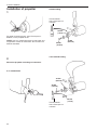
Installation of propeller
1
2-blade folding
Thread sealant
Volvo Penta part no.
1161056
10 Nm
(7 lb.ft)
Put water resistant grease, Volvo Penta part no.
828250, on the propeller shaft.
NOTE! Use zinc sacrificial anodes for salt water and
magnesium anodes for freshwater. Zinc anodes are
fitted as standard.
2
20 Nm
(15 lb.ft)
70 Nm
(52 lb.ft)
3 and 4-blade folding
Mount the propeller according to instruction
2 or 3-blade fixed
70 Nm
(52 lb.ft)
20 Nm
(15 lb.ft)
Thread sealant
Volvo Penta part no.
1161056
50
10 Nm
(7 lb.ft)
Oil quality and filling
Fill engine and S-drive with oil.
Also see Operator's manual.
Oil quality engine:
VDS–2, ACEA E5, API CH–4
Viscosity (at –5° – +50°C constant ambient air
temperature) : SAE 15W/40, SAE 20W/50
EngineApprox. volumes
liters (US qts)
D1-131.9 (2.0)
D1-202.8 (3.0)
D1-303.5 (3.7)
D2-406.0 (6.3)
D2-5510.5 (11.0)
D2-7510.5 (11.0)
NOTE! Always check oil dipstick for final topping up.
Oil quality reverse gear:
ATF (Automatic Transmission Fluid),
Dexron II, III
Reverse gear Volumes
liters
(US qts)
MS100.35
(0.37)
MS150.56
(0.59)
MS250.75
(0.79)
HS251.80
(1.90)
Oil quality S-drive:
ATF (Automatic Transmission Fluid),
Dexron II, III TypeVolumes
liters
(US qts)
130S, SR
150S, SR
2.9
3.0
(3.0)
(3.1)
51
Notes
52
References to Service Bulletins
GroupNo.
DateConcerns
........................................................................................................................................................................................... ........................................................................................................................................................................................... ........................................................................................................................................................................................... ........................................................................................................................................................................................... ........................................................................................................................................................................................... ........................................................................................................................................................................................... ........................................................................................................................................................................................... ........................................................................................................................................................................................... ........................................................................................................................................................................................... ........................................................................................................................................................................................... ........................................................................................................................................................................................... ........................................................................................................................................................................................... ........................................................................................................................................................................................... ........................................................................................................................................................................................... ........................................................................................................................................................................................... ........................................................................................................................................................................................... ........................................................................................................................................................................................... ........................................................................................................................................................................................... ........................................................................................................................................................................................... ........................................................................................................................................................................................... ........................................................................................................................................................................................... ........................................................................................................................................................................................... ........................................................................................................................................................................................... ........................................................................................................................................................................................... ........................................................................................................................................................................................... ........................................................................................................................................................................................... ........................................................................................................................................................................................... ........................................................................................................................................................................................... ........................................................................................................................................................................................... ........................................................................................................................................................................................... ........................................................................................................................................................................................... ........................................................................................................................................................................................... ........................................................................................................................................................................................... ...........................................................................................................................................................................................
...........................................................................................................................................................................................
53