1
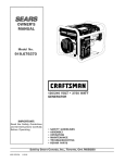
OWNER'S
MANUAL
Model
No.
919.679580
I CRRFTSMRNI
120/240
VOLT ° 5800
GENERATOR
IMPORTANT:
Read the Safety Guidelines
and All Instructions Carefully
Before Operating
Sold
MGP-679580
4/29/99
by Sears
•
•
•
•
•
•
WATT
SAFETY GUIDELINES
ASSEMBLY
OPERATION
MAINTENANCE
TROUBLESHOOTING
REPAIR PARTS
Canada,
Inc., Toronto,
Ont.
M5B2B8
TABLE
Warranty ....................................................
Safety Guidelines
Assembly
Operation
2
...................................
3-8
..................................................
8
..............................................
Maintenance
Service
OF CONTENTS
...........................................
and Ajustments
.........................
9-12
Storage
...................................................
Troubleshooting
15
......................................
15
Parts ..................................................
16-18
EPA Codes
21-22
........................................
14
How To Order Parts .................
14
Fran_ais
HORSE POWER
GASOLINE CAPACITY
OIL CAPACITY
DATEPURCHASED:
Back Cover
11 HP
7 GALLON
48 OZ.
MODEL NO:
I
SERIAL NO:
STOREWHERE PURCHASED:
MAINTENANCE
AGREEMENT
The Craftsman Warranty, plus a Maintenance Agreement, provide maximum value for your Sears products. Contact your
nearest Sears store for details.
ADDRESS
CITY
CUSTOMER
TELEPHONE:
RESPONSIBILITIES
Read and observe the safety rules.
Record the above information about your unit
so that you will be able to provide it in case
of loss or theft.
Follow a regular schedule in maintaining, caring for and using
your generator.
Follow the instructions under "Customer Responsibilities"
and "Storage" sections of this owner's manual.
FULL ONE YEAR WARRANTY ON CRAFTSMAN
GENERATORS
For one year from the date of purchase, when this Craftsman generator is maintained and operated according
instructions in this owner's manual, Sears will repair, free of charge, any defect in material and workmanship.
If your Craftsman Generator is used for commercial
original date of purchase.
to the
or rental purposes, this warranty applies for only 90 days from the
FULL ONE YEAR WARRANTY ON CRAFTSMAN
ENGINE
For one year from the date of purchase, when this Craftsman engine is maintained and operated according
instructions in this owner's manual, Sears will repair, free of charge, any defect in material and workmanship.
to the
If your Craftsman engine is used for commercial or rental purposes, this warranty applies only for 90 days from the
date of purchase. This warranty does not cover: Expendable items such as spark plugs and air filters, which become
worn during normal use.
Repairs necessary because of operator abuse or negligence, including damage resulting from no oil being supplied to
the engine or failure to maintain the equipment according to the instructions contained in this owner's manual, are not
covered under warranty.
WARRANTY SERVICE IS AVAILABLE BY RETURNING THE GENERATOR TO THE NEAREST SEARS SERVICE CENTER.
This warranty gives you specific legal rights and you may also have other rights, which vary from PROVINCE TO
PROVINCE.
Sold by Sears Canada, Inc., Toronto, Ont.
2 -- ENG
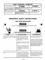
SAFETY
This manual contains information that
is important
for you to know and
understand. This information relates
to protecting
YOUR SAFETY
and
PREVENTING EQUIPMENT PROBLEMS. To help you recognize this
information, we use the symbols to
the right. Please read the manual and
pay attention to these sections.
GUIDELINES
I _
DANGER
- DEFINITIONS
I _CAUTION
I
URGENT SAFETY INFORMATION
- A HAZARD THAT WILL CAUSE SERIOUS INJURY
OR LOSS OF LIFE.
I _WARNING
Information
equipment.
I
I
IMPORTANT
SAFETY INFORMATION
- A
HAZARD THAT MIGHT CAUSE SERIOUS
INJURY OR LOSS OF LIFE.
IMPORTANT
for preventing
Information
pay special
NOTE
that
you
attention
I
damage
to
I
should
to.
SAFETY INSTRUCTIONS
• SAVE THESE
INSTRUCTIONS
•
When using this product basic precautions should always be followed
including the following:
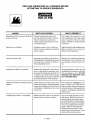
RISK OF ELECTROCUTION
HAZARD
Attempting to connect generator directly
to the electrical system of any building
structu re.
AND FIRE
WHAT COULD HAPPEN
Back feeding electricity through a
building's electrical system to the
outside utility feed lines could endanger repair persons attempting to
restore service.
Attempting to connect to the incoming
utility service could result in electrocution.
Restoration of electrical service while
the generator is connected to the incoming utility could result in a fire or
serious damage if a isolator switch is
not installed.
Inadequate electrical grounding of gene rator.
The failure of one of the generator's
electrical devices, a broken wire, wet
surfaces, etc. could result in the entire
unit becoming electrically charged.
Contact with electrically charged
surfaces could result in electrocution.
3 -- ENG
HOW TO PREVENT IT
Never back feed electricity through a
structure's electrical system.
To connect to a structure's electrical
system in a safe manner and always
have a Double-Th row Transfer Switch
installed by a qualified electrician, in
compliance with local ordinances.
(When installing a Double-Throw
Transfer Switch, a minimum of 10
gauge wiring must be used.)
Make sure that the unit is connected
to an appropriate electrical ground, in
accordance with the requirement of
the National Electric Code. See page
8 for grounding instructions.
READ AND UNDERSTAND
ALL WARNINGS
BEFORE
ATTEMPTING
TO OPERATE GENERATOR.
RISK OF ELECTROCUTION
HAZARD
AND FIRE (cont'd)
WHAT COULD HAPPEN
HOW TO PREVENTIT
Water is an excellent conductor of
electricity! Water which comes in
contact with electricity charged
components can transmit electricity to
the frame and other surfaces, resulting
in electrical shock to anyone contacting them.
Operate generator in a clean, dry, well
ventilated area. Make sure hands are
Contact with worn or damaged extension
cords could result in electrocution.
Inspect extension cords before use
and replace with new if required.
Use of undersize extension cords could
result in overheating of the wires or attached items, resulting in fire.
Use proper size (wire gauge) cordset
for application.
Use of ungrounded cordsets could prevent operation of circuit breakers and result in electrical shock.
Always use electrically
cordset.
Placing generator on or against highly
conductive surface, such as a steel walkway or metal roof.
Accidental leakage of electrical current
could charge conductive surfaces in contact with the generator.
Place generator on low conductivity
surface such as a concrete slab.
Improper
tor.
Exceeding the load capacity of the generator by attaching too many items, or
items with very high load ratings to it
could result in overheating of some items
or their attachment wi ring resulting in fire
or electrical shock.
Read the load rating chart and instructions on page 9, 10 and 11. Make sure
that the summation of electrical loads
for all attachments does not exceed
Attempting to use the unit when it has
been damaged, or when it is not functioning normally could result in fire or
electrocution.
Do not operate generator with mechanical or electrical problem. Have
unit repaired by an Authorized Service Center.
Removal of guarding could expose electrically charged components and result
in electrocution.
Do not operate generator with protective guarding removed.
Operation of generator in rain, wet, icy,
or flooded conditions.
Use of worn damaged, undersized or ungrounded extension cords.
connection
of items to genera-
Operation of unit when damaged, or with
guards or panels removed.
4 -- ENG
dry before touching unit.
grounded
the load rating of the generator.
READ AND UNDERSTAND
ALL WARNINGS
BEFORE
ATTEMPTING
TO OPERATE GENERATOR.
RISK OF FIRE
HAZARD
WHAT COULD HAPPEN
HOW TO PREVENTIT
Attempting to fill the fuel tank while the
engine is running.
Gasoline and gasoline vapors can
become ignited by coming in contact
with hot components such as the
muffler, engine exhaust gases, or from
an electrical spark.
Turn engine off and allow it to cool
before adding fuel to the tank. Equip
area of operation with a fire extinguisher certified to handle gasoline
or fuel fires.
Sparks, fire, hot objects
Cigarettes, sparks, fires, or other hot
objects can cause gasoline or gasoline
vapors to ignite.
Add fuel to tank in well ventilated area.
Make sure there are no sources of
Improper storage of fuel
Improperly stored fuel could lead to accidental ignition. Fuel improperly secured
could get into the hands of children or
other unqualified persons.
Store fuel in a container designed to
hold gasoline. Store container in secure location to prevent use by others.
Inadequate ventilation for generator
Materials placed against or near the generator or operating the generator in areas where the temperature exceeds 104°
F. ambient can interfere with its proper
ventilation features causing overheating
and possible ignition of the materials.
Operate generator in a clean, dry, well
ventilated area a minimum of four feet
Tampering with factory set engine speed
settings.
Engine speed has been factory set to
provide safe operation. Tampering with the
engine speed adjustment could result in
overheating of attachments and could
cause a fire.
Never attempt to "speedup" the engine to obtain more performance.
Both the output voltage and frequency
will be thrown out of standard by this
practice, endangering attachments
and the user.
Overfilling the fuel tank -fuel
Spilled fuel and its vapors can become
ignited from hot surfaces or sparks.
Use care in filling the tank to avoid
spilling fuel. Make sure fuel cap is
secured tightly and check engine
for fuel leaks before starting engine.
Move generator away from refueling
area or any spillage before starting
engine. Allow for fuel expansion.
Keep maximum fuel level 1Ainch
belowthe tip of the fuel tank. Never
refuel with the engine running.
spillage.
5 -- ENG
ignition near the generator.
from any objects or wall. DO NOT
OPERATE UNIT INDOORS OR IN
ANY CONFINED AREA.
READ AND UNDERSTAND
ALL WARNINGS
BEFORE
ATTEMPTING
TO OPERATE GENERATOR.
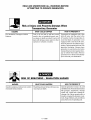
Risk of Injury and Property Damage
Transporting
Generator
HAZARD
WHAT COULD HAPPEN
Fire, Inhalation, Damage to Vehicle
Surfaces
Fuel or oil can leak or spill and could
result in fire or breathing hazard, serious injury or death can result. Fuel or oil
leaks will damage carpet, paint or other
surfaces in vehicles or trailers.
RISK OF BREATHING
HAZARD
Gasoline engines produce toxic carbon
monoxide exhaust fumes.
- INHALATION
WHAT COULD HAPPEN
Breathing exhaust fumes will cause serious injury or death.
When
HOW TO PREVENT IT
If generator is equipped with a fuel
shut-off valve, turn the valve to the
off position before transporting to
avoid fuel leaks. If generator is not
equipped with a fuel shut-off valve,
drain the fuel from tank before transporting. Only transport fuel in an CSA
approved container. Always place
generator on a protective mat when
transporting to protect against damage to vehicle from leaks. Remove
generator from vehicle immediately
upon arrival at your destination
HAZARD
HOW TO PREVENT IT
Operate generator in clean, dry, well
ventilated area. Avoid enclosed areas
like garages, basements, storage
sheds, etc., which lack a steady exchange of air. Never operate unit in a
location occupied by humans or animals. Keep children, pets and others
away from area of operating unit.
6 -- ENG
READ AND UNDERSTAND
ALL WARNINGS
BEFORE
ATTEMPTING
TO OPERATE GENERATOR.
RISK OF UNSAFE
HAZARD
Operation
manner.
of generator
OPERATION
WHAT COULD HAPPEN
in careless
Operation of voltage sensitive appliances
without a voltage surge protector.
HOW TO PREVENTIT
All sources of energy include the potential for injury. Unsafe operation or maintenance of your generator could lead to
serious injury or death to you or others.
• Reviewand understand all of the
Any gasoline operated household generator will incur voltage variations causing damage to voltage sensitive appliances or result in fire.
Always use U.L. listed voltage protector to connect voltage sensitive
appliances (TV, computer, stereo,
etc.). Failure to use a U.L. listed voltage surge protector will void the warranty on your generator.
operating instructions and warnings in this manual.
• Become familiarwith the operation
and controls of the generator.
Know how to shut it off quickly.
• Equip area of operation with a fire
extinguisher certified to handle
gasoline or fuel fires.
• Keep children or others away from
the generator at all times.
Notice: A multiple outlet strip is not
a surge protector make sure you use
a U.L. listed voltage surge protector.
RISK OF HOT SURFACES
HAZARD
Contact with hot engine and generator
components.
WHAT COULD HAPPEN
Contact with hot surfaces, such as engines exhaust components, could result
in serious burns.
RISK OF MOVING
HAZARD
Contact with moving parts can result in
serious injury.
During operation, touch only the control surfaces of the generator. Keep
children away from the generator at
all times. They may not be able to
recognize the hazards of this product.
PARTS
WHAT COULD HAPPEN
The generator contains parts which rotate at high speed during operation.
These parts are covered by guarding to
prevent injury.
7 -- ENG
HOW TO PREVENTIT
HOW TO PREVENT IT
Never operate generator with guarding or cover plates removed. Avoid
wearing loose fitting clothing or jewelry which could be caught by moving parts.
READ AND UNDERSTAND
ALL WARNINGS
BEFORE
ATTEMPTING
TO OPERATE GENERATOR.
RISK
HAZARD
LIFTING
WHAT COULD HAPPEN
Lifting a very heavy object.
CARTON
FROM
HOW TO PREVENT IT
Serious injury can result from attempting to lift too heavy an object.
The generator is too heavy to be lifted
by one person. Obtain assistance
from others before you try to move it.
CONTENTS
• Main Unit
• Owner's Manual
• Battery Connector Cables
oi
Battery
Main
Unit
Owner's
Manual
GROUNDING
CAUTION: Read owner's manual. Do not attempt to
operate equipment until you have read Owner's Manual
for Safety, Operation, and Maintenance Instructions.
REMOVE
GENERATOR
FROM
Bracket
CARTON
• Open carton from top.
• Cut carton along dotted lines.
Battery
Connector
Cables
THE GENERATOR
This generator should be grounded to help prevent
accidental electrical shock. Shown below is a picture of
the grounding lug supplied on your generator. First, drive
a 3/4" or 1" diameter copper pipe or rod into the ground
close to the generator set. The pipe must penetrate moist
earth. Using #10 gauge wire, connect one end of the wire
into the grounding lug. Next, connect the other end of the
wire to the copper pipe or rod using an approved ground
clamp.
• Remove all carton inserts.
• Remove generator through opening in carton.
IMPORTANT: Before any attempt to start your generator
be sure to check engine oil (See OPERATION under
Adding Engine Oil on page 11)
/
Grounding
8 -- ENG
Lug
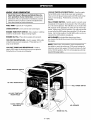
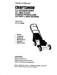
KNOW YOUR
GENERATOR
Read this Owner's Manual and Safety Rules before operation of your Generator, Compare this
illustration with your generator to familiarize yourself
with the location of various controls and adjustments.
Save the manual for future references.
FUEL TANK- Capacity of 7 US gallons.
CHOKE SWITCH-
Lever used to start cold engine.
ENGINE RUN/STOP SWITCH- Sets engine in starting
mode for recoil starter - Stops running engine.
ENGINE OIL FILL- Place where engine oil is poured.
120 VOLT RECEPTACLES - Used to supply 1800 watts
of electrical power per receptacle. Protected by a 15
amp circuit breaker.
120 VOLT TWlSTLOCK RECEPTACLE - Used to
supply 2900 watts of electrical power per receptacle.
Protected by a 25 amp circuit breaker.
ENGINE
RUN/STOP
120/240 TWISTLOCK RECPTACLE - Used to supply
the full 5800 watts of electrical power per receptacle
when a 240 volt plug is being used and 2900 watts when
using a 120 volt plug. Protected by a 25 amp circuit
breaker.
FULL POWER SWITCH - Switch used to convert every
receptacle on the panel, when placed in the 120 position,
to a 120 volt receptacle. This will allow you to receive the
full capacity of the generator by using all 120 volt receptacles. When in the 120/240 position, you will only be able
to use half of the 5800 watts when using the 120 volt receptacles. But in this position, the full 5800 watts can be received in the 240 twistlock receptacle.
AIR CLEANER- Includes filter element and foam
pre-cleaner that limits the amount of dirt that enters
the engine.
NOTE: When in the 120 position, each receptacle has
the ability to reach the maximum 7500 surge wattage for
inductive motors that require 7500 watts or below to start.
In the 120/240 position, the 120 volt receptacles will only
reach 3750 surge watts.
SWITCH
120 VOLT
POWER
120 VOLT TWISTLOCK
RECEPTACLES
120/240
TWISTLOCK
RECPTACLE
AIR CLEANER
ENGINE
9 -- ENG
OIL FILL
SWITCH
RECEPTACLES
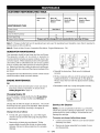
Battery
Your generator is equipped with 120-volt duplex receptacles, a 120-volt twistlock receptacle and a 120/240-volt
twistlock receptacle.
To obtain electric start capability, you must install a (12
volt - 45 A.H.) battery. The battery should be properly
serviced and fully charged prior to installation.
The unit is equipped with a 15-amp circuit breaker for the
120-volt duplex receptacles and two 25-amp circuit breakers for the 120-volt twistlock and for the 120/240-volt
twistlock receptacle. These circuit breakers are provided
to protect the generator against electrical overload. If the
circuit breaker trips, unplug all electrical loads from the
generator. Let the circuit breaker cool down. Push circuit
breaker button to reset.
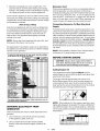
FULL POWER
Installation
Install the battery
as follows:
• Place battery in rack with terminals facing towards
generator head.
•
Place battery bracket over battery as shown (opposite battery terminals).
•
Connect black battery cable from battery post
indicated with NEGATIVE (-) to frame with bolt as
shown below.
•
Connect red battery cable from battery post indicated with POSITIVE, (+) to right post on starter
solenoid.
SWITCH
Your Craftsman generator has a full power switch on the
control panel. This switch has two positions: 120 VOLT
ONLY, and 120/240 VOLT.
120 Position
When placed in the 120 position, (shown below) every receptacle on the panel will be converted to a 120 volt receptacle. 240-volt power is not available. This position allows
full capacity of the generator to be received by using all
120-volt receptacles. While in the 120 position, each receptacle has the ability to reach the maximum 7500 surge
wattage for inductive motors that require 7500 watts or below to start.
120V
120/240
120/240V
Position
When in the 120/240 position, (shown below) only half of
the 5800 watts can be received when using the 120-volt
receptacles and the 120/240-volt twistlock receptacle will
be converted to allow the full 5800 watts to be received
from this one receptacle. Also in this position, the 120-volt
receptacles will only reach a maximum of 3750 surge watts.
120V
sole_+)
Positive
I Battery Cable
Connection
GENERATOR
CAPACITY
Exceeding the rated capacity of your generator can
result in serious damage to your generator and connected
electrical devices. You should observe the following to
prevent overloading the unit:
120/240V
IMPORTANT:
Do not move the full power switch while
powering electrical equipment. Unplug all items before
moving the switch. Failure to do so can damage the switch.
• Starting and running wattage requirements must be
calculated to match your generator wattage capacity.
10 -- ENG
Resistiveloadappliances
suchas lightbulbs,TV's
andmicrowaves,
havethesamestartingandrunning
wattage.Thewattageusedforcalculating
thecapacity
canusuallybefoundoneachoftheseappliances.
Someinductiveappliances
andtoolswilllistonthemotor
nameplate,thestartingandrunningvoltageandamperage
requirements.
Usethefollowingformulatoconvertvoltage
andamperage
towattage:
Cord
When using an appliance or tool at a considerable distance
from the generator, a 3-wire extension cord that has a
3-blade grounding plug and 3-slot receptacle that accepts
the tool's plug should be used. A cord of adequate size
must be used. A minimum of 12 gauge wire size with at
least a 20 amp draw can be used. When amperage exceeds 20 amps al 0 gauge wire size should be used.
Connecting
(Volts X Amp = Watts)
Inductive load appliances and tools such as refrigerators,
air compressors and washers require approximately 2 to
4 times the listed running wattage for starting the equipment. This initial load only lasts for a few seconds on
start-up but is very important when figuring your total
wattage to be used.
NOTE: Always start your largest electric motor first, and
then plug in other items, one at a time.
The guide below is provided to assist you in determining
the appliances and tools that can be run with the wattage
capacity of your generator.
"re _el_t
_e right _rator
for _rQur n_,
#f the ltem_ to be _n _t the sa_e tim,
Extension
total _
Generator
To Main
Electrical
Supply
Potential hazards exist when a electrical generator is connected to the main electrical supply coming into the house.
It is at that point that the generator could feed back into the
utility company's system causing possible electrocution of
workers who are repairing electrical lines. To avoid back
feeding of electricity into utility systems, a double-throw
transfer switch should be installed between the generator and utility power. This device should be installed by a
licensed electrician and in compliance with all local electrical codes.
NOTE: When installing a Double-ThrowTransfer
a minimum of 10 gauge wiring must be used.
Switch,
wa'r_e
BEFORE
I
STARTING
ENGINE
every start. Running engine low of oil or out of oil
CAUTION:
check
engine
oil level
before
could result Always
in serious
damage
to the
engine.
Adding
Engine
I
I
Oil
Your generator has been shipped without oil in the
engine. Begin by removing the oil dipstick and plug. Start
pouring the oil in slowly.
The engine will hold approximately 48 ounces of oil.
Before filling engine with oil, make sure the generator is
on level ground. Next, pour the oil in slowly until the oil
level reaches the second to last thread. Once the oil level
reaches this point, the engine will be full of oil.
OBTAINING
ELECTRICITY
GENERATOR
FROM
There are basically two ways to obtain electricity form a
generator:
•
Use of extension cords directly form the generator
to the appliance, lights, tools, etc.
•
Use of a double-throw transfer switch installed
directly to the main electrical supply outside of the
house.
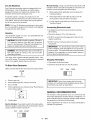
NOTE: When adding oil to the engine crankcase, use a
high quality detergent oil classified "For Service SF,SG,SH"
rated SAE 30 weight. Use no special additives. Select the
oil's viscosity grade according to your expected operating
tern perat ures.
SAE Viscosity
Grades
4
;TARTI
11 -- ENG
N6
TEMPERA]ORE
RANGE
ANTICIPATED
BEFORE
NEXT
OIL
CHANGE
Low Oil Shutdown
Manual Starting: Grasp rope handle and pull slowly until
resistance is felt. Then pull cord rapidly to overcome compression, prevent kickback and start engine.
Your Craftsman generator engine is equipped with Low
Oil Shutdown. Low Oil Shutdown is a safety device
designed to protect your engine from damage in the
event the oil level in the crankcase is low.
If while the engine is running, the oil gets low, it will
automatically shut itself down and will not restart until the
oil is added. If the oil is low before start-up, the generator will not start until oil is added.
NOTE: The Low Oil Shutdown mechanism is very sensitive. You must fill the engine to the full mark on the dipstick
to inactivate this safety device.
Gasoline
When engine starts, gradually move choke lever to
"Full Run Position."
•
If the engine fails to start after (3) pulls, move the
choke position and pull starter rope again.
•
For hot engine starts make sure choke lever is in the
"Full Run Position."
Connecting
Electrical
Loads
• Let engine run and warm up for about five minutes
after starting.
• Plug in the desired 120 or 240 volts tools.
Your generator engine is 4 cycle. Use unleaded fuel only.
Never mix oil with gasoline.
CAUTION: Never fill fuel tank completely. Fill tank to
1/2" below the bottom of the filler neck to provide
space for fuel expansion. Wipe any fuel spillage from
engine and equipment before starting engine.
I
•
• DO NOT connect 240 volt equipment to the 120 volt
duplex receptacles.
• DO NOT connect 3-phase loads to the panel
receptacles.
IMPORTANT" You should always add up the rated
watts of all lights, tools and appliances you are powering at one time. This total should not exceed the rated
capacity of you generator or circuit breaker rating of
the receptacle supplying power.
tank when engine is running or hot. Do not smoke
WARNING: Never fill fuel tank indoors. Never fill fuel
when filling fuel tank.
Use clean, fresh, regular unleaded gasoline with a minimum of 85 octane. Do not mix oil with gasoline. If unleaded
fuel is not available, leaded fuel may be used.
Stopping
To Start
• Switch the start/off switch to the off position.
Your Generator
The Engine
• Disconnect all electrical loads.
Make sure fuel shutoff valve is turned to the open position.
OFF
RUN
START
CLOSE
Remove gas cap.
IMPORTANT: Never store engine with fuel in tank,
indoors, or in enclosed, poorly ventilated areas or where
fuel fumes may reach an open flame.
Add unleaded gasoline, slowly to fuel tank.
Do not overfill.
On the engine there is a choke/run lever. Place this lever
to the choke position.
.Q=
GENERAL
The warranty of the generator does not cover items that
have been subjected to operator abuse or negligence. To
receive full value from the warranty, operator must maintain
the generator as instructed in this manual.
Crank engine.
Electric Starting: Press starter switch to the start position.
When the engine is started the switch will remain in the run
position until the switch is turned off.
OFF
RECOMMENDATIONS
RUN
Some adjustments will need to be made periodically to
maintain your generator.
START
12 -- ENG
CUSTOMER
RESPONSIBILITIES
TABLE
Before
each
Every 25
Hours of Every
Season
use
MAINTNENANCE
Every 50
Hours of Every
Season
Every 100
Hours of Every
Season
TASK
Check oil level
X
See Note 2
See Note 1
Change oil
Clean Air Filter Assembly
X
Check Spark Plug
X
Prepare Unit for Storage
x
Prepare unit for storage if it is to remain idle for more than 30 days.
Note 1: Change oil after first two (2) operating hours and every 50 operating hours thereafter, more often if operated in
extreme dusty or dirty conditions.
Note 2: Check oil after 5 hours of operation (See below - Engine Maintenance - Oil.)
GENERATOR
MAINTENANCE
Your generator should be kept clean and dry at all times.
The generator should not be stored or operated in
enviroments that includes excessive moisture, dust or any
corrosive vapors. If these substances are on the generator,
clean with a cloth or soft bristle brush. Do not use a garden
hose or anything with water pressure to clean the generator. Water may enter the cooling air slots and could possibly damage the rotor, stator and the internal windings of the
gen head.
All adjustments in the Maintenance section of this manual
should be made at least once each season.
ENGINE
MAINTENANCE
Oil
•
Reinstall the drain plug. Make sure it is tightened
securely.
• Fill the crankcase with new oil of the proper type (See
Adding Oil Section), to the Full mark on the dipstick.
Always check the level with the dipstick before adding
more oil.
• Reinstall the oil fill cap or plug and tighten securely.
Oil level should be checked prior to each use and at
least every 5 hours of operation. To check oil see
Adding Engine Oil on page 11.
Changing
Engine Oil
For a new engine, change oil after the first 5 operating
hours. Thereafter, change oil after every 50 hours of
operation.
Change the oil while the engine is still warm. The oil will
flow freely and carry away more impurities. Make sure the
engine is level when filling, checking or changing oil.
Change
•
the oil as follows:
To keep dirt, grass clippings, etc. out of the engine,
clean the area around the drain plug and plug before
removing it.
Remove the oil drain plug and dipstick. Tilt the
engine slightly towards the oil drain to obtain better
drainage. Be sure to allow ample time for complete
drainage.
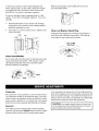
Service
Air Cleaner
NOTE: Do not use petroleum solvents, e.g., kerosene,
which will cause the cartridge to deteriorate. Do not use
pressurized air to clean cartridge. Pressurized air can
damage the cartridge.
To service air cleaner follow these steps:
•
Loosen cover screws.
assembly from base.
•
Remove air cleaner assembly from inside of cover
and disassemble.
13 -- ENG
Remove cover and air cleaner
To service pre-cleaner, wash in liquid detergent and
water. Squeeze dry in a clean cloth. Saturate in engine
oil. Squeeze in clean, absorbent cloth to remove ALL
EXCESS oil. If very dirty or damaged, replace it.
Before running engine, clean muffler area to remove
all combustible debris.
To service cartridge, clean by tapping gently on a flat
surface. If very dirty or damaged, replace it. Do not oil
cartridge
_//_
•
Reassemble retainer on pre-cleaner and cartridge
(screen side of pre-cleaner toward cartridge pleats.)
Install this assembly in cover.
•
Insert tabs on cover into slots in base. Tighten cover
screws securely.
Clean
and Replace
CLEAN
Spark
Plug
Change the spark plug every 100 hours of operation or
once each year, whichever comes first. This will help
your engine to start easier and run better.
.030" (0.76MM)
WIRE GAUGE
Clean
RESISTOR
Guard/Muffler
Do not clean with a forceful spray of water because water
could contaminate fuel system. With a brush or cloth
clean finger guard after every use to prevent engine
damage caused by overheating.
Carburetor
The carburetor of your generator is pre-set at the factory.
The carburetor should not be tampered with. If your generator is used at an altitude in excess of 4000 feet, performance may be affected. If so consult with your nearest
Sears Service Center regarding high altitude set changes.
Governor
Your engine governor maintains the constant operating
speed of your generator. DO NOT tamper with the engine
governor which is factory set for proper engine speed.
Over-speeding your engine above factory high speed setting can be dangerous and could possibly cause personal
injury or property damage. If you believe the engine is running too fast or slow, take your generator to a Authorized
Sears Service Center for repair and adjustment.
on the engine and when sufficient power is not availI CAUTION:
Low life
engine
impose a heavy load
able the engine
could speeds
be shortened.
14 -- ENG
I
I
If you are going to store your generator for more than 30
days, use the following information as a guide to prepare
the generator for storage.
STORAGE
• Disconnect the spark plug wire and remove the
spark plug.
• Add one teaspoon of oil through the spark plug hole.
INSTRUCTIONS
• Place rag over spark plug hole and pull the recoil a
few times to lubricate the combustion chamber.
CAUTION: Never store generator with fuel in the
tank indoors or in enclosed, poorly ventilated areas,
where fumes can reach an open flame, spark or pilot
light as on a furnace, water heater, clothes dryer or
other gas appliances.
Engine
• Replace the spark plug, but do not connect the spark
plug wire.
NOTE: If a fuel stabilizer is not used, all gasoline must
be drained from the tank and carburetor to prevent gum
deposits from forming on these parts and causing
possible malfunction of the engine.
Preparation
• Add fuel stabilizer to fuel tank to minimize the
formation of fuel gum deposits during storage.
Generator
• Run engine at least 10 minutes after adding stabilizer
to allow it to enter the fuel system.
• Clean the generator as outlined on Page 13 (Generator
Maintenance)
• Next shut off engine.
• Check that cooling air slots and openings on generator
are open and unobstructed.
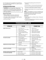
PROBLEM
Engine will not start
CAUSE
CORRECTION
1.
Low on fuel or oil.
1. Add fuel or oil.
2.
Ignition switch in "Off" position.
2. Turn to "ON" position
3.
Faulty spark plug.
3. Replace spark plug.
4.
5.
Choke in wrong position.
Fuel shut-off valve in closed
4. Adjust choke accordingly.
5. Open fuel shut-off valve.
position.
No electrical output
Repeated circuit breakertripping
Generator
overheating
DC does not have power with the
circuit breaker depressed
6.
Unit loaded during start-up.
6. Remove load from unit.
7.
Spark plug wire loose.
7. Attach wireto spark plug.
1.
2.
Faulty receptacle.
Circuit breaker kicked out.
1. Have Service Center replace.
3.
4.
Defective capacitor.
Faulty power cord.
3. Have Service Center replace
capacitor.
5.
GFCI switch breaker kicked out (if
equipped)
4. Repair or replace cord.
1.
Overload
1. Reduce load.
2.
Faulty cords or equipment.
2. Check for damaged, bare, or
frayed wires on equipment.
Replace.
1.
Generator overloaded.
1. Reduce load.
2.
Insufficient ventilation.
2. Move to adequate supply of
fresh air.
2. Depress and reset.
5. Depress and reset.
1. Faulty rectifier
1. Have Service Center replace.
2. Faulty windings in stator
2. Have Service Center replace.
3. Faulty wire harness
3. Have Service Center replace.
15 -- ENG
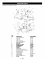
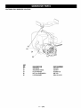
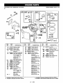
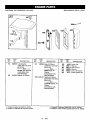
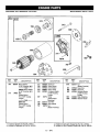
CRAFTSMAN
5800
GENERATOR
919.579580
1
22
\
\
15
KEY
NO.
1
2
3
4
5
6
7
8
9
10
11
12
13
14
15
16
17
17A
18
19
20
21
DESCRIPTION
FUEL TANK SCREWS
FUELTANK
FUEL CAP
FUEL HOSE
FUEL LINE CLAMP
DRAINCOCK GROMMET
TANK DRAINCOCK
ENDCOVER
SCREW #10-24 x 9/16
FRAME ASSEMBLY
HEAT SHIELD
WASHER
GROUND LUG
SCREW, CAP 5/16-18 X 3/4
SCREW HEXWASHER, UNSLOTTED
LOCK NUT 5/16-18
ISOLATOR (FRONT)
ISOLATOR (REAR)
LOCKWASHER
GROUND STRAP
HEX CAP SCREW 5/16-18
ENGINE
16 -- ENG
PART NUMBER
91895680
GS-0444
GS-0443
GS-0225
GS-0227
GS-0446
GS-0437
GS-0077
SSF-553-1
GS-0631
GS-0432-1
SSN-632
GS-0117
SS-12-CD
SSF-928
SSF-8150
GS-0033
GS-0433
SSN-1619-ZN
GS-0118
95829230
GS-0634
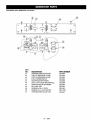
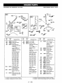
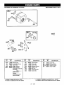
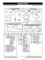
CRAFTSMAN
5800
GENERATOR
919.579580
23
24
25
KEY
NO.
22
23
24
25
26
DESCRIPTION
SOLENIOD
SOLENIOD CABLE
FLATWASHER
NUT 1/4-20 HEXKEPS
LOCKWASHER
17 -- ENG
PART NUMBER
GS-0545
GS-0647
SS-6506-CD
SSF-575
SSN-16-19-ZN
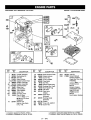
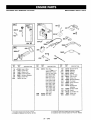
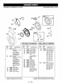
CRAFTSMAN
5800
GENERATOR
919.579580
40
ORIENT
27
28
WiTH VENTS
TORQUE
DOWNWARD
TO 204-264
TORQUE
AS SHOWN
IN-LBS
UNTIL THREADS
35
36
RUN OUT
TORQUE
TO (;0-70 IN-LRS
SHOWN FOR
REFERENCE ONLY
SHOWN FOR
REFERENCE ONLY
KEY
NO.
27
28
29
3O
31
32
33
34
35
36
37
38
39
4O
DESCRIPTION
LOCK WAS HER 3/8
CAP SCREW 3/8-16 x 1
ROTOR ASSEMBLY
STATOR THRU BOLT
STATOR ASSEMBLY
WASHER 11/16OD x 11/32
NUT 5/16-24
ROTOR THRU BOLT
BEARING SUPPORT
HEX NUT 1/4-20
CAPACITOR
CAPACITOR BRACKET
SCREW 10-32
DRIVE END ADAPTER
PART NUMBER
SS N-619
SSF-577
GS-0637
GS-0640
GS-0639
SS-6506-CD
SSF-576
GS-0638
GS-0521
SSF-575
GS-0592
GS-0595
SSF-553
GS-0076
ITEM NOT SHOWN
*DIODES
GS-0082
18 -- ENG
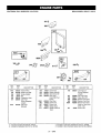
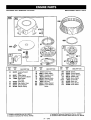
CRAFTSMAN
5800
GENERATOR
919.579580
KEY
NO.
41
42
43
44
45
46
47
48
49
50
51
DESCRIPTION
4 PRONG TWISTLOCK 240V
CIRCUIT BREAKER 15AMP
CIRCUIT BREAKER 25 AMP
FULL POWER SWITCH
ON/OFF(ON/OFF/START)
GFCI 120 V/15AMP RECEPTACLE
SWITCH FACE PLATE RESET
NUT, HEX JAM
SCREW #6-32 x 5 TORX
SCREW 10-9 x .50 PLASTITE
3 PRONG TWlSTLOCK 120V
19 -- ENG
PART NUMBER
GS-0455
GS-0024
GS-0645
GS-0045
GS-0046
GS-0806
GS-0207
SSF-595
SSF-583
SSF-3156
GS-0021
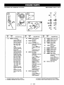
CRAFTSMAN
5800
GENERATOR
919.579580
BRIGGS
4 CYCLE
ENGINE
MODEL
3O6
729
REF,
NO.
PART
NO.
REF,
NO.
DESCRIPTION
, PART
NO.
DESCRIPTION
REE
NO,
PART
NO.
DESCRIPTION
,L,,,,,,,, ,,, ,, .....
1
2
3
497411
399265
*391086
5
212914
7 _271866
8
8A
9
10
498038
495736
_27803
94621
11
11A
13
280819
280225
94622
Cylinder Assembly
Bushing/Seal
Kit
Seal-Oil
Head-Cylinder
Gasket-Cylinder
Tube-Breather
Tube-Breather
Screw-Hex.
13A
94776
Stud-Hex.
15
94239
Plug-Oil
92736
75
225137
Head
Breather Assembly
Breather Assembly
Gasket-Breather
Screw-Hex.
Drive
Drain
Note
Plug-Oil
Drain
(Magnetic)
Washer-Flat
Used on Type No(s).
0140, 1140.
87 _,491323 Seal-Governer Shaft
306
224882 Shield-Cylinder
3O7
94930 Screw-Hex.
308
224897 Cover-Cylinder
337
802592 Plug-Spark
354
94726 Nut-Hex.
383
89838 Wrench-Spark Plug
552
491893 Bushing-Gov. Crank
635
66538 Boot-Spark Plug
729
281396 Clip-Wire
261463 Seat-Valve
869
(Intake)
87O
262924 Seat-Valve
(Exhaust)
871
261961 Bushing-Guide
(Exhaust)
978 -_271736 Gasket
979
494807 Cover-OIL GARD®
982
94139 Screw-Hex.
1019
1058
497156
273682
Label Kit
Owner's Manual
EmissionEngines
(Used After Code Date
97063000).
Note
273130 Owner's
Manual
Emission Engines
(Used Before Code
Date 97070100).
272848 Owner's
Manual
Non Emission Enginee
Included in Carburetor Gasket Set-Part No. 497069,
O Included in Valve Overhaul Gasket Set-Pad No. 498538.
* Included in Gasket Set-Part No. 497511.
Included in Carburetor Kit-Part No. 497450.
20 -- ENG
CRAFTSMAN
5800
GENERATOR
919.579580
BRIGGS
MODEL#
256427-1162-E1
35
868
41_
42_
-J;
REF.
NO.
PART
NO.
16
491645
REF.
NO.
_RT
NO.
Crankshaft
25
4_2_
Note -399723 Crankshaft
26
4_8_
Used on Type No(s).
0101, 0130, 0601,
27
2831_
DESCRIPTION
DESCRIPTION
on Type No(s).
0015, 0020,
0027, 0028,
0139, 0140,
0158,
0515,
0528,
1015,
0173,
0525,
0696,
1020,
Dipper-Conn.
Screw-Conn.
33
34
261185
261462
Valve-Exhaust
Valve-intake
35
65906
Spring--Valve
95101500).
Note --
36
26828
(Intake)
Spring-Valve
260924
Pin
40
221596
(Exhaust)
Retainer-Valve
41
42
292260
494553
Keeper-Valve
Date 95101600).
Pin-Piston
45
146
262248
94196
Tappet-Valve
Key-Timing
(Standard)
(Used After Code Date
95101500).
-Note
299691 Pin-Piston
741
262932
Gear-Timing
(Used After Code Date
Lock-Piston
(Used Before Code
28
498319
(Standard)
(Used Before Code
Date 95101600).
498320 Pin-Piston
0512,
0527,
1012,
1025,
Rod
Rod
Retainer-Valve
93040200).
Note
262135 Gear-Timing
(Used Before Code
868
497212
Date 93040300).
Seal-Valve
(.005" O.S.)
1027, 1028, 1029,
1140, 1156.
497428 Crankshaft
(Used After Code Date
95101500).
391286 Pin-Piston
Used on Type No(s).
1174.
497130 Crankshaft
(.005" O.S.)
Used on Type No(s).
0121.
DESCRIPTION
222329
92909
(Used After Code Date
Used on Type No(s).
0143, 1196.
491642 Crankshaft
Used
0012,
0025,
0115,
PART
NO.
30
32
Piston Assembly
(Standard)
Ring Set
(Standard)
Lock-Piston
Pin
0660, 0661,0695,
1101, 1130, 1161,
1195.
491635 Crankshaft
Used on Type No(s).
0135, 0635, 1135.
491644 Crankshaft
REE
NO.
29
490348
(Used Before Code
Date 95101600).
Rod-Connecting
(Standard)
Note -490469
Rod-Conn.
(.020" Undersize)
•
• Included in Carburetor Gasket Set-Part No. 497069.
O Included in Valve Overhaul Gasket Set-Part No. 498538.
Included in Gasket Set-Part No. 497511.
Included in Carburetor Kit-Part No. 497450.
21 -- ENG
CRAFTSMAN
5800
GENERATOR
919.579580
BRIGGS
22 -- ENG
MODEL#
256427-1162-E1
CRAFTSMAN
5800
GENERATOR
919.579580
BRIGGS MODEL#
255427-1162-
E1
965
_
104_
5
LMT NUMBE_=
13
LOCATION
_
I
1091
188A 12T
0
REF.
NO.
PART
NO.
50
214170
51 e_272708
51A _-_272707
53
94778
93
94
e281346
496589
94A
95
98
498030
e94098
495800
104
105
106
e231789
e231935
e231856
108
123
125
127
•
224666
94616
497451
•
Included
Included
DESCRIPTION
Manifold- Intake
Gasket-Intake
Gasket-Intake
Stud-Carburetor
Mounting
Bushing-Throttle
Shaft
Valve-Idle Adjustment
(Used on LMT 175)
Note
494383 Valve-Idle
Adjustment
(Used on LMT 101)
Valve-Idle Adjustment
Screw-Slotted
Screw-Idle
Speed
Pin-Float Hinge
Valve-Needle
Seat-Inlet
Valve-Choke
Screw-Torx®
Carburetor
REF.
NO.
PART
NO.
DESCRIPTION
130
224539
131
497846
133
494381
137 •.281165
138 e_281164
141
497160
142
499744
Throttle Valve Kit
Throttle Valve Kit
Float-Carburetor
Gasket-Float Bowl
Washer
Choke Shaft Kit
Nozzle-Carburetor
(Standard)
(Used on LMT t 75)
Note -• 497448 Nozzle-Carb.
(Standard)
(Used on LMT 101)
690145 Nozzle-Carb.
(Standard)
(Used on LMT 176)
499826
REF.
NO.
147
186A
634
950
965
975
987
1091
PART
NO.
DESCRIPTION
e497472 Jet-Pilot
(Used on LMT 101)
493496 Connector-Hose
e494455 Seal-Spring Assembl'_
94642 Screw-Bowl
Mounting
94010 Nut-Hex.
495933 Bowl-Float
e281166 Sea!-Throttle Shaft
281364 Cap-Limiter
Nozzle-Carb.
(High Altitude)
Hex.
(Used on LMT 175)
497449 Nozzle-Carb.
(LMT 101 and 175)
Note -690144 Carburetor
(High Altitude)
(Used on LMT 101)
499744 Noz.zle-Carb.
(LMT 176)
(High Altitude)
(Used on LMT 176)
Plug-Welch
(Sold in Kit Only)
in Gasket Set-Part No. 497511.
in Carburetor Kit-Part No. 497450.
Included in Carburetor Gasket Set-Part No. 497069.
Included in Valve Overhaul Gasket Set-Part
No. 498538,
23 -- ENG
CRAFTSMAN
5800
GENERATOR
919.579580
BRIGGS
MODEL#
256427-1162-E1
692 _
268
RER
_O
PART
NO,
DESCRiPTiON
+ RIEK
NO.
_i_
75A
49_59
_4a_her _
95A
!66
2_
493280
_2
2692_4
$_,w_i_e
_peed
Nci!_;W_n_
_pr_n_,,,Ge_mor
#6$CR_#TiON
_O+
R_
1'4;O.
PART
NO.
DBSOR!FT_ON
_6a049 Ur_k_Thr_le
4962_
N_ .....
499q07 B_acke{Go#iroN
(Used _e_ Code Oa_e
_r
_e_
_
............
......
t:_t 2
_5,
0101
0189
01_&
05_5
Nole
001&
_327
0115
0!40
0173
0525
26_3_
r_4.
_&
OJ3_.0007;
oo2& 00o,
0120
0i2&
01s&
01_
0-_,
01_1_0424.
0129. 0132.
0_34,e_s&
0!87 0!53¢
0570 _I
4_SI 3 Br_Coa#e_
2_72_
Z_a_e_704,_8_)
o_21.
21_
_;
_?
496868 W'i_,
398_2_ In_a'_or
_82
2_1062 N_q4_...
16_
2_i
9
t070, !1S2 t133
1174_1i95 !196;
Sp_!_4$ove_r_
Oa._e97042_).
2_B
_218a_ C_._3asin
Usede_ T_peNe(@
0020
0_8
I')130_
014&
05!2
0_7
1012, t015, 1_9
t_5 1_7 !028,
1_9 110t !!30,
20g,A
_@J
_32a_
(u_ed A_ef _
Da_
0_0_0_30_0143,
060_
_r_iaded _ Gas_e__2ei_a_t N# 49751t
24 -- ENG
_25
_ew-,
Shou]_r
CRAFTSMAN
5800
GENERATOR
919.579580
BRIGGS
MODEL#
256427-1162-E1
50i
85i _''
|
J_
524
_
NO.
_54A
_m _
NO
90_76
@_,S_!Pl
iON
N_-He_
_:blacl#d_J#_Va_e 0 e _a& G_ ®
25 -- ENG
.........
CRAFTSMAN
5800
GENERATOR
919.579580
BRIGGS
MODEL#
256427-1162-E1
478
826 ._,
RS_;
NO.
474B
478
_-,,_.
PART
NO
OE_C_iP"_©N
_}
NO
DESC R_Pq!ON
8_
3_3_;! 4 Wil_A!_6rria_
_9_595 A#ema_
39_0
U_e_ aa _y#e No(s)
Pa_'_
26 -- ENG
CRAFTSMAN
5800
GENERATOR
919.579580
BRIGGS
MODEL#
256427-1162-E1
,i
REE
NO
PA_T
NO,
D_C_i:PTiON
REF
NO,
t 88
i98
PARr
NO
_6_'?
_39_a
Og:$ORiPTiON
S_w-<_hat
R_E
NO
O_
_
Lm÷R_e_
_A
483_29 F'i_ter_Wue
Va_v_
27 -- ENG
D_CR_P _ ON
{@Jt _oRequif_
_t
187
pA_
NO,
9_
9_
_oA
a_a_8
Cap_Fue,_ Tank
_
_rack_,4::_! lank
_2_
Brac_o4:_
Tank
4_29_0
uel Taak
CRAFTSMAN
5800
GENERATOR
919.579580
BRIGGS
MODEL#
256427-1162-E1
467
969_
535
U
642
159
445
I.
0
I
I.
0
258
,,,, ,,
REE
NO,
11A
159
•
PART
NO,
DESCRIPTION
280819 Tube-Breather
(Used After Code Date
95010100).
Note
281426 Tube-Breather
(Used Before Code
Date 95010200).
261358 Support-Air Cleaner
REF,
NO.
161
PART
NO,
DESCRIPTION
497669
Base-Air Cleaner
(Used After Code Date
950101 O0).
Note
498544 Base-Air
Cleaner
(Used Before Code
Date 95010200).
163 _A-273101 Gasket-Air Cleaner
(Used After Code Date
95010100).
Note
_272706
Gasket- Air
Cleaner
(Used Before Code
Date 95010200).
Included in Gasket Set-Part No. 497511.
Included in Carburetor Kit-Part No, 497450.
REF.
NO.
258
445
467
535
642
969
PART
NO.
DESCRIPTION
94930 Screw-Hex.
496077 Filter-Air
280715 Knob-Control
492889 Filter-Air
281357 Cover-Air Cleaner
94777 Screw--Slotted Hex.
i Included in Carburetor Gasket Set-Part No. 497069.
O Included in Valve Overhaul Gasket Set-Part No. 498538.
28 -- ENG
CRAFTSMAN
5800
GENERATOR
919.579580
BRIGGS
MODEL#
256427-1162-E1
883
505
663_
884_
188_
346_
863
450A
883
REE
NO.
PART
NO.
DESCRIPTION
REF
NO.
PART
NO,
,,, ,,,,
53A
81
188
300
300A
94755
223016
94627
497470
498984
Screw-Torx®
Lock-Muffler Screw
Screw-Hex.
Muffler-Exhaust
Muffler-Exhaust
(Used After Code Date
97012300).
Note
493963 MufflerExhaust
(Used Before Code
Date 97012400).
301
346
346A
436
450A
505
613
663
REF.
NO.
DESCRIPTION
494447
94786
93705
497469
93852
94726
93927
93343
,,
,
Pipe-Exhaust
Screw-Hex.
Screw-Hex.
Manifold-Exhaust
Washer-Flat
Nut-Hex.
Screw-Shoulder
Screw-Hex.
_r Included in Gasket Set-Part No. 497511.
• Included in Carburetor Kit-Part No. 497450.
PART
NO.
DESCRIPTION
,
836
94186
863
224560
883 _272293
884
392649
Screw-Hex.
Bracket-Muffler
Gasket-Exhaust
Clamp-M uffler
4, Included in Carburetor Gasket Set-Part No, 497069.
0 Included in Valve Overhaul Gasket Set-Part No. 498538.
29 -- ENG
CRAFTSMAN
5800
GENERATOR
919.579580
BRIGGS
MODEL#
256427-1162-E1
........
d%.,_.:_%,
73A/ .o
...........................
iLxII_I
23 _:_ ,F_:,,
°
"<_ _[Sl
% 716
/
=I
..........
I
QU /
73
304
IIF,
P_IT
NO
(U_d Ale_ Cede D_I@
9606P,
S@}
NO,
BiESCRIPT!O_
73A
_537
75B
22_0_!
_
497474
NO
_7
NOo
1954_
DIIOIIPTION
Ct_ve_-SIailef
D_'_e
_rew-_hll_8
ISA
4!!1:1
Q_te
lli_heil
g
(U_
)
N_
_ere
!@0,
24
31
37A
_BgB
_488B
2_7_
7_
_4874
{n_J)
)
....
Ca_
&w.l
33_
_7
_716
2se4_i
P_
1_g,
1Q_I 1027
110!
It&g,
11_,
1_
!130_
i134
1140,
!!_
U_
Ce Type Nee}
t!£@.
1t35_
H{a,
t16%
r
_5
0_7_ O_.a
060 _ 06_,
Ge_r-R_
r_TI,
f_&
06g& 06_
@
S_x_4ex,
_08
I_20.
la_sla_ m V_ve t_#j
30 -- ENG
Gmm_ 8e_-,#a_ No 4g_&
CRAFTSMAN
5800
GENERATOR
919.579580
BRIGGS
MODEL#
256427-1162-E1
I
I
71
68 ©
/
REF.
NO,
PART
NO.
55
393576
56
57
58
295871
490179
66894
59
60
63
64
490653
490652
260414
281204
"
DESCRIPTION
Housing-Rewind
Starter
Pulley--Stader
Spring-Rewind Starter
Rope-Starter
(75" Long)
Insert-Gdp
Grip-Starter Rope
Spring-Ratchet
Adapter-Spring
REF,
NO.
65
66
67
68
70
71
373
608
655
PART
NO.
94128
399671
394897
63770
298799
394506
92987
390391
222598
DESCRIPTION
Screw-Hex.
Clutch-Starter
Housing-Clutch
Bali-Clutch
Ratchet-Clutch
Cover-Ratchet
Nut-Hex.
Starter-Rewind
Anchor-Rewind
Spring
REF.
NO.
668
930
1016
110
309
310A
311
503
510
PART
NO,
225124
280685
490B17
225137
497595
94003
497608
806000
497606
DESCRIPTION
Spacer
Guard-Rewind
Spacer-Rewind
Washer-Flat
Motor-Starter
Screw-Flex.
Brush Set
Strap-Starter
Drive-Starter
i
•
....
,_ included in Carburetor Gasket Set-Part No, 497069.
Included in Valve Overhaul Gasket Set-Part No, 498538,
Included in Gasket Set-Part No. 497511.
Included in Carburetor Kit-Part No, 497450.
31 -- ENG
CRAFTSMAN
5800
GENERATOR
919.579580
BRIGGS
MODEL#
256427-1162-E1
783
1051
803
797A
544
797 _
503
801
REF
NO.
PART
NO.
309
693054
310
•
94003
DESCRIPTION
Motor-Starter
(3 5/8" Housing Lgth.)
Note
499521 Motor-Starter
(4 3/8" Housing Lgth.)
Bolt
(Starter Motor)
(For 3 5/8" Housing
Length)
Note
95035 Bolt
(Starter Motor)
(For 4 3/8" Housing
Length)
REE
NO,
311
503
510
513
544
697
729
783
797
PART
NO.
DESCRIPTION
497608 Brush Set
806000 Strap-Starter
497606 Drive-Starter
398003 Clutch-Drive
497603 Armature-Starter
(3 5/6" Housing
Length)
94773
Screw
(Starter Motor
Mounting)
225170
Clip-Wire
693059
Gear-Starter
92278
Nut
(Starter Terminal)
Included in Gasket Set-Part No, 497511.
Included in Carburetor Kit-Part No. 497450.
RIEF.
NO,
797A
PART
NO.
693167
801
802
803
497626
497607
497604
1051
1090
263080
497605
DESCRIPTION
Nut
(Starter Terminal)
Cap-Drive
Cap-End
Housing-Starter
(3 5t8" Housing
Length)
Ring-Retaining
Retainer-Brush
Included in Carburetor Gasket Set-Part No. 497069.
O Included in Valve Overhaul Gasket Set-Part No. 498538.
32 -- ENG
CRAFTSMAN
5800
GENERATOR
919.579580
BRIGGS
121 CARBURETOR
1270
108
138
KIT
987@
MODEL#
256427-1162-E1
358 GASKET SET
95_
87@
93 _
116 _
163 _
12
524
634_
977 CARBURETOR
GASKET
SET
1095 VALVE OVERHAUL
137_
REE
NO.
PART
NO.
DESCRIPTION
3 *391086 Seal-Oil
7 _'_r271866 Gasket-Cylinder Head
9 2P,r27803 Gasket-Breather
12 *272125 Gasket-Crankcase
1.015" Thick, Std.)
Note
_r272219 GasketCrankcase
(.005" Thick)
_272220 GasketCrankcase
(.009" Thick)
Seal-Oil
20 *291675
51 o.272708
Gasket-Intake
Gasket-Intake
51A_272707
87 *491323
Seal-Governor Shaft
93 e281346
Bushing-Throttle Shaft
95
e94098
Screw-Slotted
104
e231789
Pin-Float Hinge
105
e231935
Valve-Needle
106
e231856
Seat-Inlet
.
•
138
REF.
NO.
116
121
127
137
138
142
147
163
GASKET SET
(_
PART
NO.
DESCRIPTION
_270920 Seal-.-O-Ring
497450 Carburetor Kit
e
Plug-Welch
(Sold in Kit Only)
Gasket-Float Bowl
•,281165
o.281164
Washer
Nozzle-Carbu retor
e497448
(Standard)
(Used on LMT 101)
•497472
Jet-Pilot
(Used on LMT 101)
_:_,k273101 Gasket-Air Cleaner
(Included in Gasket
Sets Packaged After
Code Date 95010700)
Note
_272706 GasketAir Cleaner
(Included in Gasket
Sets Packaged Before
Code Date 95010200)
REF.
NO.
358
524
634
883
977
978
987
1095
PART
NO.
DESCRIPTION
497511 Gasket Set
*281370 Seal-Fill Tube
•494455 Seal-Spring
Assembly
_,_272293 Gasket-Exhaust
497069 Gasket SetCarburetor
-k271736 Gasket
• 281166 Seal-Throttle Shaft
498538 Gasket Set-Valve
Overhaul
÷ Included in Carburetor Gasket Set-Part No. 497069.
O Included in Valve Overhaul Gasket Set-Part No. 498538.
Included in Gasket Set-Part No. 497511.
Included in Carburetor Kit-Part No. 497450.
33 -- ENG
Briggs & Stratton Corporation (B&S), the California Air Resources Board (CARB)
and the United States Environmental Protection Agency (U.S. EPA)
Emission Control System Warranty Statement (Owner's Defect Warranty Rights and Obligations)
Inthe interest of the environment, B&S enginesthat meet strict emisTO CERTIFIED ENGINES PURCHASED IN CALIFORNIA IN 1995
sion requirements are labeled, 'q-his engine conforms to 1995 - 1998
AND THEREAFTER, WHICH ARE USED IN CALIFORNIA, AND
California emission regulations for ULGE engines and U.S. EPA
TO CERTIFIED MODEL YEAR 1997 AND LATER ENGINES
Phase I regulations for small non-road engines."
WHICH ARE PURCHASED AND USED ELSEWHERE IN THE
EMISSION CONTROL WARRANTY COVERAGE IS APPLICABLE
UNITED STATES.
California and United States Emission Control Defects Warranty Statement
there has been no abuse, neglect or improper maintenance of your
CARB, U.S. EPA and B&S are pleased to explain the Emission
ULGE engine.
Control System Warranty on your 1996 and later utility or lawn and
garden equipment (ULGE) engine. In California, new ULGE engines
Your emission control system includes parts such as the carburetor,
produced on or after August 1, 1995 must be designed, built and
air cleaner, ignition system, muffler and catalytic converter. Also
equipped to meet the State's stringent anti-smog standards., Elseincluded may be connectors and other emission related assemblies.
where in the United States, new non-road, spark-ignition engines
Where a warrantable condition exists, B&S will repair your ULGE
certified for model year 1997 and later, must meet similar standards
engine at no cost to you including diagnosis, parts and labor.
set forth by the U.S. EPA. B&S must warrant the emission control
system on your engine for the periods of time listed below, provided
Briggs & Stratton Emission Control Defects Warranty Coverage
ULGE engines are warranted relative to emission control parts
below. Ifany covered part on your engine is defective, the part will be
defects for a period of two years, subject to provisions set forth
repaired or replaced by B&S.
Owner's Warranty Responsibilities
You are responsible for presenting your ULGE engine to an AuthoAs the ULGE engine owner, you are responsible for the performance
rized B&S Service Dealer as soon as a problem exists. The undisof the required maintenance listed in your Operator/Owner Manual.
puted warranty repairs should be completed in a reasonable amount
B&S recommends that you retain att your receipts covering mainteof time, not to exceed 30 days.
nance on your ULGE engine, but B&S cannot deny warranty solely
for the lack of receipts or for your failure to ensure the performance of
if you have any questions regarding your warranty rights and
all scheduled maintenance.
responsibilities, you should contact a B&S Service Representative
at 1-414-259-5262.
As the ULGE engine owner, you should however be aware that B&S
The emission warranty is a defects warranty. Defects are judged on
may deny you warranty coverage if your ULGE engine or a part has
normal engine performance. The warranty is not related to an in-use
failed due to abuse, neglect, improper maintenance or unapproved
emission test.
modifications.
Briggs & Stratton Emission Control Defects Warranty Provisions
The following are specific provisions relative to your Emission Control Defects Warranty Coverage. It is in addition to the B&S engine warranty
for non-regulated engines found in the Operator/Owner Manual.
1. Warranted Parts
3. NO Charge
Repair or replacement of any Warranted Part will be performed
Coverage under this warranty extends only to the parts listed
at no charge to the owner, including diagnostic labor which leads
below (the emission control systems parts) to the extent these
to the determination that a Warranted Part is defective, if the
parts were present on the engine purchased.
diagnostic work is performed at an Authorized B&S Service
a. Fuel Metering System
Dealer. For emissions warranty service contact your nearest
•
Cold start enrichment system (soft choke)
Authorized B&S Service Dealer as listed in the "Yellow Pages"
under "Engines, Gasoline," "Gasoline Engines," "Lawn
•
Carburetor and internal parts
Mowers," or similar category.
•
Fuel Pump
4. Claims and Coverage Exclusions
b. Air Induction System
Warranty claims shall be filed in accordance with the provisions
•
Air cleaner
of the B&S Engine Warranty Policy. Warranty coverage shall be
•
Intake manifold
excluded for failures of Warranted Parts which are not original
B&S parts or because of abuse, neglect or improper maintec. Ignition System
nance as set forth inthe B&S Engine Warranty Policy. B&S is not
•
Spark plug(s)
liable to cover failures of Warranted Parts caused by the use of
•
Magneto ignition system
add-on, non-original, or modified parts.
5. Maintenance
d. Catalyst System
•
•
e.
2.
Catalytic converter
Exhaust manifold
•
Air injection system or pulse valve
Miscellaneous Items Used in Above Systems
•
Vacuum, temperature, position, time sensitive valves
and switches
•
Connectors and assemblies
Length of Coverage
B&S warrants to the initial owner and each subsequent purchaser
that the Warranted Parts shall be free from defects in materials
and workmanship which caused the failure of the Warranted
Parts for a period of two years from the date the engine is delivered to a retail purchaser.
34 -- ENG
Any Warranted Part which is not scheduled for replacement as
required maintenance or which is scheduled only for regular
inspection to the effect of "repair or replace as necessary" shall
be warranted as to defects for the warranty period. Any
Warranted Part which is scheduled for replacement as required
maintenance shall be warranted as to defects onlyfor the period
of time up to the first scheduled replacement for that part. Any
replacement part that is equivalent in performance and durability
may be used in the performance of any maintenance or repairs.
The owner is responsible for the performance of all required
maintenance, as defined in the B&S Operator/Owner Manual.
6. Consequential Coverage
Coverage hereunder shall extend to the failure of any engine
components caused by the failure of any Warranted Part still
under warranty.
Briggs
& Stratton
welcomes
warranty
repairandapologizes
to youfor beinginconvenienced.
AnyAuthorized
Service
Dealer
mayperform
warranty
repairs.
Mostwarranty
repairs
arehandled
routinely,
butsometimes
requests
forwarranty
service
maynotbeappropriate.
Forexample,
warranty
would
notapplyifengine
damage
occurred
because
ofmisuse,
lack
ofroutinemaintenance,
shipping,
handling,
warehousing
or
improper
installation.
Similarly,
warranty
isvoidif theserial
number
oftheenginehasbeenremoved
ortheenginehas
beenalteredormodified.
Ifacustomer
differswiththedecision
oftheService,
Dealer, an
investigation will be made to determine whether the warranty
applies. Ask the Service Dealer to submit all supporting facts to
his Distributor or the Factory for review. If the Distributor or the
Factory decides that the claim is justified, the customer will be
fully reimbursed for those items that are defective. To avoid
misunderstanding
which might occur between the customer
and the Dealer, listed below are some of the causes of engine
failure that the warranty does not cover.
Improper
maintenance:
The life of an engine depends upon the conditions under
which it operates, and the care it receives. Some applications,
such as tillers, pumps and rotary mowers, are very often used
in dusty or dirty conditions, which can cause what appears to
be premature wear. Such wear, when caused by dirt, dust,
spark plug cleaning grit, or other abrasive material that has
entered the engine because of improper maintenance, is not
covered by warranty.
This warranty covers engine related defective material
and/or workmanship _
and not replacement or refund
of the equipment to which the engine may be mounted.
Nor does the warranty
extend to repairs required
because of:
1.
PROBLEMS
CAUSED BY PARTS THAT
ORIGINAL BRIGGS & STRATTON PARTS.
ARE
2.
Equipment controls or installations that prevent starting,
cause unsatisfactory
engine performance,
or shorten
engine life. (Contact equipment manufacturer.)
3.
Leaking carburetors, clogged fuel pipes, sticking valves,
or other damage, caused by using contaminated or stale
fuel. (Use clean, fresh, lead-free gasoline and Briggs &
Stratton gasoline stabilizer, Part No. 5041 .)
4.
5.
Repair or adjustment of associated parts or assemblies
such as clutches, transmissions,
remote controls, etc.,
which are not manufactured by Briggs & Stratton.
6. Damage or wear to parts caused by dirt, which entered
the engine because of improper air cleaner maintenance,
re-assembly, or use of a non-original air cleaner element
or cartridge. (At recommended intervals, clean and re-oil
the Oil-Foam@ element or the foam pre-cleaner, and
replace the cartridge.) Read "Owner's Manual."
7.
Parts damaged by overspeeding, or overheating caused
by grass, debris, or dirt, which plugs or clogs the cooling
fins, or flywheel area, or damage caused by operating the
engine in a confined area without sufficient ventilation.
(Clean fins on the cylinder, cylinder head and flywheel at
recommended intervals.) Read "Owner's Manual."
8.
Engine or equipment parts broken by excessive vibration
caused by a loose engine mounting, loose cutter blades,
unbalanced blades or loose or unbalanced impellers,
improper attachment of equipment to engine crankshaft,
overspeeding or other abuse in operation.
9.
A bent or broken crankshaft, caused by striking a solid
object with the cutter blade of a rotary lawn mower, or
excessive v-belt tightness.
10. Routine tune-up or adjustment of the engine.
11. Engine or engine component failure, i.e., combustion
chamber, valves, valve seats, valve guides, or burned
starter motor windings, caused by the use of alternate
fuels such as, liquified petroleum, natural gas, altered
gasolines, etc.
NOT
35 -
Parts which are scored or broken because an engine was
operated with insufficient or contaminated lubricating oil,
or an incorrect grade of lubricating oil (check oil level daily
or after every 8 hours of operation. Refill when necessary
and change at recommended intervals.) Read "Owner's
Manual."
ENG
For in-home
major brand repair service:
Call 24 hours a day, 7 days a week
1-800-4-MY-HOME
Para pedir servicio
de reparacibn
'°
(1-800-469-4663)
a domicillo
--
1-800-676-5811
In Canada for all your service and parts needs call
1-800-665-4455
Au Canada pour tout le service ou les pieces
For the repair
or replacement
parts you need:
Call 6 am - 11 pm CST, 7 days a week
PartsDirect TM
1-800-366-PART
Para ordenar
piezas con entrega
(1-800-366-7278)
a domicillo
--
1-800-1659-7084
For the location of a Sears Parts and Repair Center in your area:
Call 24 hours a day, 7 days a week
1-800-488-1222
For information
on purchasing
a Sears Maintenance
or to inquire about an existing Agreement:
Call 9 am _
5 pm, Monday _
Saturday
1-800-827-6655
HomeCentraF
Agreement