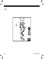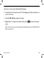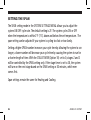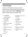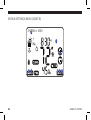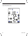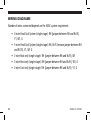
1
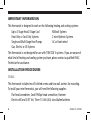
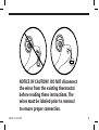
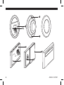
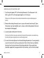
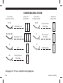
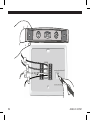
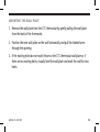
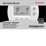
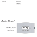
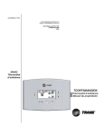
A Hunter Fan Company
2500 Frisco Ave.
Memphis, TN 38114
800-676-7861
www.climatetechnologyproducts.com
Touchscreen Programmable Thermostat
Model 43855
3 Stage Heat/2 Stage Cool
installation and
operation manual
TABLE OF CONTENTS
IMPORTANT INFORMATION.......................................4
INSTALLATION PROCEDURES.....................................4
GENERAL OPERATING INSTRUCTIONS......................21
DATE & TIME SETTINGS.............................................22
SYSTEM SETTINGS MENU..........................................27
USER SETTINGS MENU...............................................31
TEMPERATURE RANGE..............................................34
ENERGY STAR DEFAULT PROGRAMS.........................35
MANUAL OPERATION................................................36
PROGRAM OPERATION..............................................39
PROGRAM OVERRIDES...............................................46
ADDITIONAL FEATURES.............................................56
CLEAN SCREEN...........................................................56
CHANGE FILTER..........................................................60
ENERGY MONITOR FUNCTION...................................64
TROUBLESHOOTING...................................................68
WIRING DIAGRAMS...................................................72
44003-01 r051507
Touchscreen Programmable Thermostat
Model 43855
3 Stage Heat/2 Stage Cool
Congratulations!
Thank you for choosing a Climate Technology
Corporation programmable thermostat. Your new
CTC thermostat will provide years of reliable service
and year-round energy savings.
Please read this manual before beginning
installation and save this booklet for complete
operating instructions.
44003-01 r051507
IMPORTANT INFORMATION
This thermostat is designed to work on the following heating and cooling systems:
Up to 3 Stage Heat/2 Stage Cool
Heat Only or Cool Only Systems
Single and Multi-Stage Heat Pumps
Gas, Electric or Oil Systems
Millivolt Systems
2-wire Hydronic Systems
AC or Hard-wired
This thermostat is not designed for use with 110V/220 V systems. If you are unsure of
what kind of heating and cooling system you have, please contact a qualified HVAC
Technician for assistance.
INSTALLATION PROCEDURES
TOOLS
This thermostat includes two #8 slotted screws and two wall anchors for mounting.
To install your new thermostat, you will need the following supplies:
Flat-head screwdriver, Small Phillips-head screwdriver, Hammer
Electric drill and 3/16” bit, Three 1.5 Volt (AA) size alkaline batteries
44003-01 r051507
W
RC Y G
W
RC Y G
w
NOTICE OF CAUTION! DO NOT disconnect
the wires from the existing thermostat
before reading these instructions. The
wires must be labeled prior to removal
to ensure proper connection.
44003-01 r051507
W
RC Y G
RC
Y G
W
44003-01 r051507
UNINSTALLING THE EXISTING UNIT
1. Turn the system power OFF at the existing thermostat. Turn the power to the
HVAC system OFF at the main power panel or at the furnace.
(Failure to turn off the power to the existing thermostat before removal could damage your
system.)
2. Remove the existing thermostat cover to access the wires from the wall. (Some
thermostats may have multiple covers, screws or other locking devices that must
be removed or disengaged.)
3. Locate, but do not disconnect the wires.
(If wires are not visible, they may be connected to the back of the wall plate. Some models may
have doors that open to expose the wires and mounting screws.)
4. Do not let the wires slip back into the wall during disconnection. You may want to
secure the wires to the wall as you disconnect them. After all wires are labeled,
disconnect each wire and remove the existing wall plate. (Any unused wires
should be capped with an approved electrical connector, such as electrical tape.)
44003-01 r051507
44003-01 r051507
5. Using the provided stickers, label each wire according to the chart.
If the terminals are not labeled, contact a qualified HVAC technician.
NOTE: Wire colors do not always comply with standards; therefore, wire color should be ignored.
Refer to the existing terminal designation for proper identification.
If wires marked “Y” or “C” are both present, “C” may be a Common wire and provides 24 VAC
power to the unit. Connecting it greatly extends battery life. If there is no "C" wire, the thermostat
will run on battery power.
44003-01 r051507
CONVENTIONAL HVAC SYSTEMS
Y1 / Y2
if your existing
thermostat is marked:
R / RC
Y2 Y1
Cooling Stage 1 or 2
label the wire
with this sticker:
Cooling Transformer
Power Supply
R/RC
Y1 Y2
W1 / W2 / W3
C
W3 W2 W1
Heating Stage 1, 2 or 3
24 VAC Common
(if available)
W1 W2 W3
G
Fan
H
RH
Heating Transformer
Power Supply
H
Humidifier Control
G
RH
C
H
G
C
label the wire
with this sticker:
R/RC
if your existing
thermostat is marked:
RH
See pages 72-73 for a complete wiring diagram.
10
44003-01 r051507
HEAT PUMP SYSTEMS
label the wire
with this sticker:
label the wire
with this sticker:
C
Y2 Y1
Compressor Stage 1 or 2
24 VAC Common
Y1 Y2
O
W2
Auxilliary Heat
Cool Mode Powered
Reverse Valve
O
W2
E
G
Fan
E
G
Emergency Heat
G
R / RC
E
B
R/RC
24 VAC Power Supply
Heat Mode Powered
Reverse Valve
R/RC
L
System Monitor
B
H
H
L
B
W2
C
O
Y1 / Y2
if your existing
thermostat is marked:
C
if your existing
thermostat is marked:
Humidifier Control
L
H
See pages 74 for a complete wiring diagram.
44003-01 r051507
11
RC
L
O C
Y
H B W1 E
Y1 Y2 W3 W2 G RH RCR
G
W
12
44003-01 r051507
MOUNTING THE WALL PLATE
1. Remove the wall plate from the CTC thermostat by gently pulling the wall plate
from the back of the thermostat.
2. Position the new wall plate on the wall horizontally and pull the labeled wires
through the opening.
3. If the existing holes do not match those on the CTC thermostat wall plate or, if
there are no existing holes, visually level the wall plate and mark the wall for two
holes.
44003-01 r051507
13
G
Y
RC
W
14
44003-01 r051507
4. Remove the wall plate from the wall and drill two 3/16” holes where marked.
5. Tap the plastic anchors into the holes until they are flush with the wall.
6. Reposition the wall plate on the wall, pulling the wires through the wall plate
opening. Insert the mounting screws through the wall plate and into the anchors.
Verify that the wall plate is level. Securely tighten both screws.
44003-01 r051507
15
Terminal
Shield
Terminal
Screw
Jumper
Wire
16
44003-01 r051507
CONNECTING THE WIRES
1. Loosen, but do not remove the terminal screws.
NOTE: A jumper wire is provided, connecting the RH and RC terminals for systems that do not have
both an RH and RC wire. If you have both an RH and RC wire, remove this jumper; otherwise, leave
the jumper in place.
2. Complete wiring diagrams for Conventional HVAC Systems and Heat Pump
Systems are provided on pages 72-74. Match and connect the wires from the wall
to the terminals as shown. Insert wires behind the black terminal shield. Tighten
each screw after the connection is made.
3. Wrap the ends of any extra wires individually in electrical tape and carefully push
them into the wall. Push any excess wire length back into the wall to prevent
interference.
44003-01 r051507
17
18
44003-01 r051507
ATTACHING THE THERMOSTAT
1. Insert three AA alkaline batteries into the back of the thermostat.
2. Place the thermostat over the wall plate, aligning it over the terminal and battery
openings. Press the thermostat to the wall plate and it will snap into place.
NOTE: Do not force the thermostat onto the wall plate as this may damage the terminal pins. If the
thermostat does not snap into place easily, the unit may not work.
3. Restore power at the electrical panel and/or furnace.
44003-01 r051507
19
MAY 17 2006
THURSDAY
20
44003-01 r051507
GENERAL OPERATING INSTRUCTIONS
Your new CTC thermostat is easy to program and use. The front of the thermostat is a
touch screen that responds to the pressure of a finger.
You can program the thermostat to automatically readjust the temperature, humidity
and airflow to settings that you choose or you can use the pre-programmed default
settings. You can also operate the thermostat manually.
44003-01 r051507
21
DATE & TIME SETTINGS
DATE, MONTH, YEAR
MAY 17 2006
1
THURSDAY
2
3
22
44003-01 r051507
1. Touch either the month, date, year at the top of the touch screen.
2. Touch the
or
sign to adjust the setting.
3. Repeat Steps 1-2 for each setting. Touch
44003-01 r051507
to return to the main screen.
23
CLOCK
MAY 17 2006
THURSDAY
1
2
3
24
44003-01 r051507
The clock is a 12-hour clock with AM and PM settings.
1. Touch the time on the touch screen. SET CLOCK appears and the hour flashes. Note
the AM & PM indicators.
2. Touch the
or
sign to adjust the setting.
3. Repeat Steps 1-2 to adjust the minutes setting. Touch
screen.
to return to the main
NOTE: The clock can be set to automatically adjust for Daylight Savings Time in the USER SETTINGS
MENU, see pages 31-33.
44003-01 r051507
25
SETTING the span
The SPAN setting mode in the SYSTEM SETTINGS MENU allows you to adjust the
system ON/OFF cycle rate. The default setting is 2F. The system cycles ON or OFF
when the temperature is within 2°F (1°C) above and below the set temperature. The
span setting can be adjusted if your system is cycling too fast or too slowly.
Setting a higher SPAN number increases your cycle time by allowing the system to run
longer; a lower number will decrease your cycle time by causing the system to run for
a shorter length of time. With the STAGE TIMER (Option 10) set to 0, stages 2 and 3
will be controlled by the SPAN setting only. If the stage timer is set to 30, the system
will turn on the next stage based on the SPAN setting or 30 minutes, which ever
comes first.
Span settings remain the same for Heating and Cooling.
26
44003-01 r051507
SYSTEM SETTINGS MENU
The installer can set SYSTEM functions once the thermostat is installed. The
default settings are shown in bold in the following list. Options are listed inside the
parentheses. Example: the default SYSTEM TYPE is CONVENTIONAL with (HEAT
PUMP) as a second option. See pages 28-29 to change these settings.
1. SYSTEM: CONVENTIONAL
(CONVENTIONAL, HEAT PUMP)
2. FURNACE TYPE: GAS/OIL
(GAS/OIL, ELECTRIC)
3. HUMIDITY CONTROL: ON
(ON, OFF)
4. HUMIDITY SPAN (not available if HUMIDITY
CONTROL set to OFF): 1
(1, 2, 3)
5. STAGE ONE SPAN (defined on page 26): 2F
(1F, 2F, 3F)
6. STAGE TWO SPAN (not available on 1H/1C
models): 2F
(2F, 3F, 4F, 5F, 6F)
44003-01 r051507
7. STAGE THREE SPAN (not available on 1H/1C and
2H/2C models): 3F
(2F, 3F, 4F, 5F, 6F)
8. AUTO SEASON SPAN: 5F
(3F, 4F, 5F, 6F)
9. TEMPERATURE CALIBRATION: 0F
(-2, -1, 0, +1, +2)
10. STAGE TIMER: 0 minutes
(0, 30)
11. RESIDUAL COOLING TIMER: 30 seconds
(0, 30, 60, 90)
12. RESTORE FACTORY SETTINGS: NO
(YES, NO)
27
SYSTEM SETTINGS MENU (CONT'D)
SYSTEM
or USER
3
1
5
2 7
28
4 6 8
44003-01 r051507
1. Touch a blank area of the touch screen.
2. Press and hold
for 3 seconds for SYSTEM and USER settings to appear.
3. Touch SYSTEM. The selected word flashes.
4. Touch
.
5. Scroll through the first setting with the
the list on page 27 for setting options.
6. Touch
44003-01 r051507
sign to select an option. Refer to
to confirm selection and move to next setting.
7. When all settings are complete, touch
8. Touch
or
to exit.
to return to the main screen.
29
USER SETTINGS
The PERIODS PER DAY (Option 1) can be set to 0, 2 or 4. When set to 0, the
thermostat operates as a digital non-programmable thermostat.
The FILTER CHANGE INDICATOR (Option 2) runs in calendar days and can be set from
30-360 days in 15-day increments (the default is 90).
The REFRESH FAN ON (Option 3) function runs only the fan during heating or cooling
off cycles. This balances the indoor air and improves air quality by cycling the air
through the filter.
30
44003-01 r051507
USER SETTINGS MENU
The USER can also set certain functions in the USER SETTINGS MENU. The default
settings are shown in bold in the following list. Options are listed inside the
parentheses. Example: the default PROGRAMS PER DAY is 4 Periods with (0 and 2)
as options. See pages 32-33 to change these settings.
1. PROGRAMS PER DAY: 4 Periods
(0, 2, 4)
2. FILTER CHANGE DAYS: 90 Days
(30-360, in 15 day increments)
3. REFRESH FAN ON TIME: 15 Minutes
(10, 15, 20, 30)
4. CLOCK DISPLAY: ON
(ON, OFF)
5. HUMIDITY DISPLAY: ON
(ON, OFF)
6. DAYLIGHT SAVING: ON
(ON, OFF)
44003-01 r051507
7. TOUCHPAD BUZZER: ON
(ON, OFF)
8. TEMP SCALE: F
(Fahrenheit, Celsius)
9. LCD CONTRAST: 5
(0-9)
31
USER SETTINGS MENU (cont'd)
SYSTEM or USER
3
1
5
2 7
32
4 6 8
44003-01 r051507
1. Touch a blank area of the touch screen.
2. Press and hold
for 3 seconds for SYSTEM and USER settings to appear.
3. Touch USER. The selected word flashes.
4. Touch
.
5. Scroll through the first setting with the
the list on page 31 for setting options.
6. Touch
44003-01 r051507
sign to select an option. Refer to
to confirm selection and move to next setting.
7. When all settings are complete, touch
8. Touch
or
to exit.
to return to the main screen.
33
TEMPERATURE RANGE
This thermostat meets ENERGY STAR guidelines for energy efficiency. By using
the preprogrammed and default settings, this thermostat can save you money by
optimizing energy usage in heating and cooling.
30o F
(0o C)
Out of Range
"LO"
< o
30 F
34
45o F
o
(7 C)
95o F
(35o C)
Program Range
Display Range
99o F
(37o C)
Out of Range
"HI"
> o
99 F
44003-01 r051507
ENERGY STAR DEFAULT PROGRAMS
Refer to the Energy Star Default Programs Chart shown below for detailed Information
about pre-programmed settings. If customizing your programs, you can revert to the
Energy Star default programs below by pressing the
icon in the program mode.
10 pm
Program 4
Heat : 60o F (16o C)
Cool : 82o F (28oC)
Program 3
Heat : 68o F (20o C)
Cool : 78o F (26o C)
6 am
Program 1
Heat : 68o F (20o C)
Cool : 78o F (26o C)
4 pm
8 am
Program 2
Heat : 60o F (16o C)
Cool : 85o F (29o C)
44003-01 r051507
35
MANUAL OPERATION
Many people prefer to operate their thermostats manually, adjusting settings as
needed.
NOTE: PROGRAMS PER DAY must be set to 0 for manual operation. See USER SETTINGS MENU
(pages 31-33).
SET HEAT OR AC SYSTEM MODE
MAY 17 2006
THURSDAY
1
2
5
3
6
4 7
36
44003-01 r051507
1. Touch a blank area of the touch screen. SELECT FUNCTION appears.
2. Touch the
or
icon. SET SYSTEM MODE appears.
3. Scroll through the settings with the
modes:
HEAT (
AUTO (
icon, red screen)
and
icons)
4. Touch
or
sign to select one of the SYSTEM
EMHEAT (only for Heat Pump Systems)
COOL (
icon, blue screen)
OFF (no icon)
to return to the main screen.
The icon will show on the main screen if the system is heating; the
show if the system is cooling.
icon will
NOTE: If the system is running and the
or
icon is touched on the main screen, it will return
you to the SET SYSTEM MODE screen. Repeat steps 2-4 to make changes.
5. Touch the temperature icon (
).
6. Touch the
or
7. Touch
to return to the main screen.
44003-01 r051507
sign to adjust the temperature.
37
38
44003-01 r051507
PROGRAM OPERATION
CREATING CUSTOM PROGRAMS
You can program the thermostat to automatically adjust the temperature, humidity
and airflow up to four times per day. The PROGRAMS PER DAY setting must be set to
2 or 4 in USER SETTINGS, see pages 31-33.
NOTE: Program times are set in 10-minute increments. When setting a program time, note the AM
and PM indicators. Program temperatures are set in increments of 1°F (1°C). After 15 seconds
of inactivity during programming, the thermostat returns to the main display. Press
to
exit Program Mode at any time. To review any existing programs, touch any period icon to see
selections.
PERIOD ICONS
The program periods are indicated by the following icons:
Sunrise
44003-01 r051507
Daytime
Evening
Nighttime
39
CREATING CUSTOM PROGRAMS (cont'd)
This thermostat has an autorecovery function and will automatically calculate the time
needed to achieve the temperature you set. Therefore, it will be at the temperature
you select at the time you select. (Step 7, page 41).
4
5
7
8
6
1
2 3
P1
40
44003-01 r051507
1. Touch a blank area of the screen to begin programming. SELECT FUNCTION
appears at the top of the display. (Image P1)
2. Touch the
icon. PRESS PRG TO PROGRAM appears at the top of the display
along with the days of the week.
NOTE: Either 2 or 4 PERIOD icons will display depending upon how many were selected in USER
SETTINGS.
3. Touch the
icon again. SELECT ICON TO PROGRAM appears at the top of the
display. (Image P2)
4. Touch the day(s) to be programmed. A check mark is placed next to each day
selected.
5. Touch one of PERIOD icons for program settings. The selected PERIOD icon flashes
until another period is selected or
or
is touched.
6. Touch the
or
icon to select mode.
7. Touch the time display to set the program start time.
8. Touch the
44003-01 r051507
or
sign to adjust hours and minutes.
41
CREATING CUSTOM PROGRAMS (cont'd)
SELECT ICON TO PROGRAM
13
9
14
42
11
10
12
15
P2
44003-01 r051507
9. Touch the temperature display to set the temperature.
10.Touch the
or
sign to adjust numerals.
11.Touch the humidity display to set the humidity.
12.Touch the
NOTE: Touch
13.Touch
or
sign to adjust numerals.
to set the selected period to Energy Star settings. See page 35.
repeatedly to select fan mode (ON, AUTO, or REFRESH).
14.Touch
to save the settings for the selected days/period and to select new
days/period for programming.
15.Repeat instructions 1-14 to select new days and time periods to be programmed or
press
to save programs and return to the main display.
44003-01 r051507
43
FAN PROGRAM MODE
MAY 17 2006
THURSDAY
1
2
3
4
44
44003-01 r051507
1. Touch a blank area of the touch screen. SELECT FUNCTION appears.
2. Touch the
icon. SET FAN TO PROGRAM MODE appears.
3. Scroll through the fan settings with the
modes:
or
sign to select one of the fan
ON: Fan runs continuously regardless of the system mode.
AUTO: Fan runs when the system is on.
REFRESH: Fan runs on a set interval if the system does not cycle on for one hour.
PROGRAM: Fan is controlled by the settings in the programs.
4. Touch
The
to return to the main screen.
icon will show on the main screen if the fan is running.
NOTE: If the fan is running and the
44003-01 r051507
icon is touched, it will bring up the SET FAN screen.
45
PROGRAM OVERRIDES
You can either temporarily override the settings for the current program, or
permanently override all settings and adjust temperatures manually.
TEMPORARY OVERRIDE SETTINGS
SELECT HOLD TYPE
6
46
1
2
4
7
1
3 5 8
44003-01 r051507
1. Touch the temperature icon ( ) or humidity icon (
). The selected icon will
flash and SET OVERRIDE TEMPERATURE or SET OVERRIDE HUMIDITY appears,
depending upon your selection.
2. Touch the
3. Press
4. Touch the
5. Press
or
sign to adjust the setting.
and the screen displays SELECT HOLD TYPE.
or
sign to select TEMPORARY HOLD.
and the screen displays TEMPORARY HOLD – HOLD UNTIL.
6. Touch the hour and minutes and use the
or
sign to set the ending time.
7. To put both temperature and humidity on the same hold press the other icon
and repeat steps 1-2.
8. Press
44003-01 r051507
and the main display shows HOLD.
47
PERMANENT OVERRIDE SETTINGS
SELECT HOLD TYPE
48
1
2
4
1
3 5
44003-01 r051507
1. Touch the temperature icon ( ) or humidity icon (
). The selected icon will
flash and SET OVERRIDE TEMPERATURE or SET OVERRIDE HUMIDITY appears,
depending upon your selection.
2. Touch the
3. Press
4. Touch the
5. Press
44003-01 r051507
or
sign to adjust the setting.
and the screen displays SELECT HOLD TYPE.
or
sign to select PERMANENT HOLD.
and the main display shows HOLD.
49
VACATION OVERRIDE SETTINGS
SELECT HOLD TYPE
6
50
1
3
5
1
2 4 6
44003-01 r051507
1. Touch the temperature icon ( ) or humidity icon (
). The selected icon will
flash and SET OVERRIDE TEMPERATURE or SET OVERRIDE HUMIDITY appears,
depending upon your selection.
2. Press
3. Touch the
4. Press
and screen displays SELECT HOLD TYPE.
or
sign to select VACATION HOLD.
and the main display shows VACATION HOLD.
SET NUMBER OF DAYS. Numeral flashes.
5. Touch the
6. Press
44003-01 r051507
or
sign to adjust the number of days.
and the main display shows HOLD.
51
CANCEL TEMPERATURE OR HUMIDITY HOLD
MAY 17 2006
THURSDAY
1
2
52
44003-01 r051507
1. Touch the
2. Press
icon. CANCEL TEMPERATURE HOLD appears.
, the hold is released and main display returns.
NOTE: If the Temperature or Humidity is touched and override screens appear but no changes are
made, the HOLD remains and the main display returns.
44003-01 r051507
53
HOME TODAY FUNCTION
HOME TODAY overrides the program settings for periods
,
and
with
comfortable heat or cool settings while you are home. HOME TODAY ends when
period
begins.
MAY 17 2006
THURSDAY
1
2
3
4
54
44003-01 r051507
1. Touch a blank area of the touch screen.
2. Touch the
icon.
3. Touch the
TODAY.
or
4. Touch
to return to the main display.
The
sign to toggle between SET HOME TODAY and CANCEL HOME
icon will show on the main screen if it is activated.
5. Touch the
44003-01 r051507
icon and press
to deactivate the HOME TODAY feature.
55
ADDITIONAL FEATURES
The CLEAN SCREEN FUNCTION allows 30 seconds to clean the touch screen without
disturbing the existing settings.
CLEAN SCREEN
PRESS ENTER FOR CLEANING
1
2
3
56
44003-01 r051507
1. Touch a blank area of the touch screen.
2. Touch
. PRESS ENTER FOR CLEANING appears.
3. Press
to return to the main screen. A 30-second countdown begins to allow
time to clean the touch screen.
4. Use a damp cloth with a non-corrosive solvent such as water or a household glass
cleaner to clean the screen.
44003-01 r051507
57
LOCK FUNCTION
The lock function allows a user to lock the touch screen to prevent unexpected or
accidental changes.
MAY 17 2006
THURSDAY
3
5
1
4
2
6
58
7
44003-01 r051507
1. Touch a blank area of the touch screen.
2. Touch the
icon.
appears.
3. Touch
once for the first digit, twice for the second and three times for the
third digit.
4. Touch the
or
sign to adjust the setting.
5. Repeat 3-4 for each digit.
6. Touch
to return to the menu screen.
7. Touch
to confirm code and return to main screen.
The
icon will appear on the main screen.
NOTE: Once a code is set, touching the function on the main screen will bring the user to ENTER
CODE TO UNLOCK. Enter your code or use 777 which is the master unlock code.
44003-01 r051507
59
CHANGE FILTER
The FILTER CHANGE indicator icon will flash after the filter life counter expires as a
reminder to check or change your HVAC filter. Reset the filter function after you have
changed the filter. The filter change counter is set in the USER SETTING MENU for a
period of 30-360 days.
FILTER RUN TIME
HOLD FILTER KEY TO RESET
1
2 3
4
60
44003-01 r051507
1. Touch a blank area of the touch screen.
2. Touch
display.
. FILTER RUN TIME and HOLD FILTER KEY TO RESET appear on the
3. Touch and hold
for 3 seconds for time to reset. (Pressing the filter button
for less than 3 seconds will cause the Filter indicator icon to continue to appear.)
4. Press
44003-01 r051507
to return to the main screen.
61
CHANGE BATTERIES
The CHANGE BATTERIES warning indicates two stages of battery power shortage.
When the batteries are weak, the CHANGE BATTERIES warning flashes until three
new AA alkaline batteries are installed. If the batteries become too weak for normal
operation, the thermostat enters the second battery power shortage mode.
When no battery power is left, the BATTERIES USED UP warning flashes on the
display and the system turns off. The system remains off until new batteries are
installed. The thermostat resumes normal operation after new batteries are installed.
62
44003-01 r051507
AUTO RECOVERY
The AUTO RECOVERY FUNCTION allows heating and cooling systems to gradually
recover from an energy-saving set point temperature to a comfort set point
temperature. AUTO RECOVERY calculates the time needed to adjust the temperature
to the next program setting. When the thermostat is in AUTO RECOVERY mode, the
display flashes alternatively SYSTEM IN AUTO RECOVERY and the weekday.
NOTE: AUTO RECOVERY does not operate if Permanent or Temporary Holds are on.
44003-01 r051507
63
ENERGY MONITOR FUNCTION
The ENERGY MONITOR function allows you to review and monitor the effect of your
program settings on the system runtime.
MAY 17 2006
THURSDAY
1
2 4
3
5
64
44003-01 r051507
1. Touch a blank area of the touch screen.
2. Touch the
icon.
3. Scroll through the SYSTEM RUNTIME settings with the or sign to see the
system runtime in hours for TODAY, YESTERDAY, the CURRENT MONTH or the
LAST MONTH.
4. Touch and hold the
5. Touch
44003-01 r051507
icon for 3 seconds to reset the counters.
to return to the main screen.
65
ERROR MESSAGE
ERROR mode indicates an expected operation problem. The screen flashes a SYSTEM
ERROR message and shuts the system off. You must reset and the thermostat by
replacing the batteries if the thermostat has entered ERROR mode.
AUTO CUT-OFF
AUTO CUT OFF automatically turns the system off if the temperature rises above 95°F
(35°C) or drops below 40°F (4°C).
NOTE: If the HVAC system has malfunctioned, the systems no longer respond to the thermostat
controls and the AUTO CUT OFF will have no effect.
66
44003-01 r051507
COMPRESSOR PROTECTION
After the system stops running in cooling mode, there is a 3.5 minute delay before it
can be restarted to prevent compressor damage due to rapid cycling.
RESETTING THE UNIT
To restore the thermostat to the original factory settings, enter the SYSTEM SETTINGS
MENU and set Option 12 to YES. See page 27.
44003-01 r051507
67
TROUBLESHOOTING
1. My display does not appear.
1a. Check the batteries and battery connections.
1b. Reset the thermostat.
2. The auto fan feature does not operate properly.
2a. Check to see if the correct furnace type is selected under the system settings
in options.
3. My display is erratic.
3a. Replace the batteries.
4. The program will not change at my desired setting.
4a. Check that the time is set properly to AM and PM.
4b. Make sure the thermostat is not in permanent override mode.
4c. Check that the day setting is correct.
68
44003-01 r051507
5. The heating or cooling will not turn on or off.
5a. Make sure the thermostat is not in permanent override mode.
5b. Wait. There may be as much as a 4-minute delay before the system turns on
or off to protect the compressor.
5c. Check circuit breakers and switches to ensure there is enough power to the
system.
5d. Replace batteries.
5e. If applicable, make sure the furnace blower door is closed properly.
5f. If your system has 4 wires, ensure the jumper is installed between the RC and RH
terminals.
6. The display comes on but does not stay illuminated.
6a. Replace batteries.
7. My system continues to operate when the thermostat is in the off position.
7a. Replace unit.
44003-01 r051507
69
8. The touch screen permanently reads SYSTEM ERROR.
8a. Refer to page 66 for ERROR mode instructions. If ERR message remains after
battery replacement, then replace unit.
9. How do I just operate my thermostat manually?
9a. Manual operation instructions begin on page 38.
70
44003-01 r051507
NEED MORE HELP?
Is there help on the web?
Yes, visit us at http://www.climatetechnologyproducts.com for more information.
Is there someone I can call?
Yes. The CTC Technical Support is available from 7 am to 7 pm CST M-F and 8
am to 5 pm Saturday. They may be reached toll-free at 1-800-676-7861.
44003-01 r051507
71
WIRING DIAGRAMS
Number of wires connected depends on the HVAC system requirement.
• 4-wire Heat/Cool System (single stage): RH (jumper between RH and Rc/R),
Y1, W1, G
• 5-wire Heat/Cool System (single stage): RH, Rc/R (remove jumper between RH
and RC/R), Y1, W1 G.
• 2-wire Heat only (single stage): RH (jumper between RH and Rc/R), W1
• 3-wire Heat only (single stage): RH (jumper between RH and Rc/R), W1, G
• 3-wire Cool only (single stage): RH (jumper between RH and Rc/R), Y1, G
72
44003-01 r051507
Conventional HVAC Systems
Optional Jumper
RH
RC/R
Heat 24V
Supply
Cool 24V
Supply
C
Y1
Y2
W1
W2
W3
H
G
Cool
Stage 1
Cool
Stage 2
Heat
Stage 1
Heat
Stage 2
Heat
Stage 3
Humidity
Control
Fan
Control
24VAC Common
(if available)
44003-01 r051507
73
Optional
Jumper
C
RC/R
24VAC
Supply
Y1
Y2
W2
Compressor
Stage 1
Compressor
Stage 2
Auxiliary
Heat
Heat Pump Systems
E
Emergency
Heat
O
B
G
L
H
Reversing Valve
Cool
Reversing Valve
Heat
Fan
Control
System
Monitor
Humidity
Control
24VAC Common
(if available)
Number of wires connected depends on the heat pump system requirement. Not all
terminals need to be connected.
• Add jumper between W2 and E terminals on systems without an E wire.
74
44003-01 r051507
44003-01 r051507
75