1
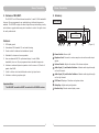
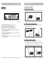
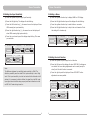
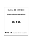
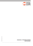
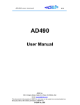
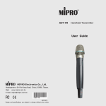
MI-808T Stereo Transmitter User Guide MIPRO Electronics Co., Ltd. Headquarters: 814 Pei-Kang Road, Chiayi, 60096, Taiwan. Web: www.mipro.com.tw E-mail: [email protected] Design and specifications are subject to change without prior notice 2 CE 4 3 7 A AS110730 WARNING ! IMPORTANT SAFETY INSTRUCTIONS ! 1. Read these instructions. 2. Keep these instructions. 3. Heed all warnings. 4. Follow all instructions. 5. Do not use this apparatus near water. 6. Clean only with a dry cloth. 7. Do not block any ventilation openings. Install in accordance with the manufacturer's instructions. 8. Do not install near any heat sources such as radiators, heat registers, stoves, or other apparatus (including amplifiers) that produce heat. 9. Do not defeat the safety purpose of the polarised or ground plug: A polarised plug has two blades with one wider than the other. The wide blade is provided for your safety. When the provided plug does not fit into your outlet, consult an electrician for replacement of the obsolete outlet. 1. FOR OUTDOOR USE: To reduce the risk of fire or electric shock, do not expose this apparatus to rain or moisture. 2. UNDER WET LOCATION: Apparatus should not be exposed to dripping or splashing and no objects filled with liquids, such as vases should be placed on the apparatus. 3. SERVICE INSTRUCTIONS: CAUTION - These servicing instructions are for use by qualified service personnel only. To reduce the risk of electric shock, do not perform any servicing other than that contained in the operating instructions unless you are qualified to do so. This symbol indicates that dangerous voltage constituting a risk of electric shock is present within this unit. 10. Protect the power cord from being walked on or pinched particularly at plug, convenience receptacles, and the point where they exit from the apparatus. This symbol indicates that there are important operating and maintenance instructions in the literature accompanying this unit. 11. Only use attachments/accessories specified by the manufacturer. 12. Use only with a cart, stand, tripod, bracket, or table specified by the manufacturer, or sold with the apparatus. When a cart is used, use caution when moving the cart/apparatus combination to avoid injury from tip-over. 13. Unplug this apparatus during lightning storms or when unused for long periods of time. 14. Refer all servicing to qualified service personnel. Servicing is required when the apparatus has been damaged in any way, such as power-supply cord or plug is damaged, liquid has been spilled or objects have fallen into the apparatus, the apparatus has been exposed to rain or moisture, does not operate normally, or has been dropped. & IC - ID THIS DEVICE COMPLIES WITH PART 74 OF THE FCC RULES AND RSS-123 ISSUE2 OF CANADA. OPERATION IS SUBJECT TO THE FOLLOWING TWO CONDITIONS: (1) This device may not cause interference. (2) This device must accept any interference, including interference that may cause undesired operation of the device. This equipment complies with FCC RF radiation exposure limits set forth for an uncontrolled environment. Disposal 15. To reduce the risk of fire or electric shock, do not expose this apparatus to rain or moisture. Disposing of used batteries with domestic waste is to be avoided! 16. Apparatus should not be exposed to dripping or splashing and no objects filled with liquids, should be placed on the apparatus. 17. Use only with the battery which specified by manufacturer. 2005-08-13 18. The power supply cord set is to be the main disconnected device. Dispose of any unusable devices or batteries responsibly and in accordance with any applicable regulations. Batteries / NiCad cells often contain heavy metals such as cadmium(Cd), mercury(Hg) and lead(Pb) that makes them unsuitable for disposal with domestic waste. You may return spent batteries/ accumulators free of charge to recycling centres or anywhere else batteries/accumulators are sold. By doing so, you contribute to the conservation of our environment! Contents Stereo Transmitter 1. Preface: 1 This system is engineered to meet the stringent requirements demanded in a variety of pro audio applications, such as by musicians, performers and directors. 2. Features of the MI-808T 2 To get the most out of your system, please read this manual thoroughly. 3. Glossary 3-4 1. Preface Characteristic of the MI-808T: 4. Operating the MI-808T 5-11 5. Important Notes 12 MI-808T is a part of a wireless monitoring system designed specially for use in stage performance and broadcasting. The main purpose of this system is to allow the user to listen to program feedback discreetly, instead of via a complicated matrix of audio cables and monitor speakers. In addition, MI808T can serve as a conference PA system or multi-lingual transmitter. To maximize audio quality, S/N ratio and dynamic range, MIPRO uses "Dynamic Signal Processing Technology" to limit spurious and background noise. Your Package Contains the Following Accessories﹕ Rack mount Brackets ×1-pair User Guide ×1 0 1 User Guide Antenna ×1 MI-808T Stereo Transmitter Switching power supply ×1 Stereo Transmitter Stereo Transmitter 3. Glossary: 2. Features of MI-808T: The MI-808T is a UHF-band stereo transmitter. In each 24 MHz bandwidth there are 16 pre-programmed, user selectable non-interfering frequencies available. The MI-808T employs the latest high-efficiency transmitting circuitry and includes a rugged metal casing which combine to make it the right choice for audio professionals. Front Panel: 8 L R LIM POWER HEADPHONE VOLUME -12 CH 04 -20 -30 FREQUENCY 81 1 . 22 5 MHz - + -40 SOURCE MI-808T Stereo Transmitter Features: 1. LCD display panel 2. International EIA standard 1/2-rack metal housing 3. Combo socket for balanced and unbalanced inputs. 4. Selectable for stereo and mono operation. 5. Uses an advanced UHF PLL synthesized design. In each 24MHz bandwidth, there are 16 pre-programmed user selectable frequencies. 6. Includes an advanced dynamic expander circuit to ensure a S/N ratio of greater than 90dB. 7. A built-in limiter circuit avoids distortion under high input levels 8. Includes a monitoring earphone jack. 1 Important Note: The MI-808T transmitter MUST be used with a MI-808R receiver. 2 2 3 4 5 6 7 (Figure 1) 1 Power Switch: Power on/off. 2 Earphone Jack: Connects to a stereo earphone to monitor audio output signals. 3 Volume Control: Adjusts the volume of the stereo earphone. 4 Audio Input (L) and Limiter Indicator: Indicates audio signal strength on the left channel. 5 Audio Input (R) and Limiter Indicator: Indicates audio signal strength on the right channel. 6 LCD Panel: Displays all functions and system status. 7 Setup Key: Adjusts setup configuration. 8 Function Key: Selects various display menus. 3 Stereo Transmitter Stereo Transmitter 4. Operating the MI-808T: Rear Panel: 1. Installation of the Antenna Coaxial cables may be used to remotely locate the transmitting antenna. ANTENNA 9 LOOP OUT L R AF IN (L) AF IN (R) MONO DC IN (12~15V) 10 11 12 13 14 (Figure 2) 2. Installation of Front Mounted Antenna 9 Transmitter Output Connector: Antenna connection. Use an accessory FB-71 rack mount kit. For best results, locate the antennas on the front panel. 10 Unbalanced Audio Output Jack (Left Channel) 11 Unbalanced Audio Output Jack (Right Channel) 12 Audio Input Jack (Left Channel): Combo socket for balanced and unbalanced signal inputs. 13 Audio Input Jack (Right Channel): Combo socket for balanced and unbalanced signal inputs. 14 DC Input Socket: Connects 15V DC power input. Positive (+) voltage for center pole of socket. 3. Installation of Extension Antenna Use the accessory AT-70 extension antennas with an MS-10 wallmounting accessory or microphone stand adaptor and connect by using quality coaxial cable. Coaxial cable lengths should be kept to a minimum. AT-70 Extension Antennas install with MS-10 wall-mounting accessory 4 5 connect by coaxial cable. Stereo Transmitter Stereo Transmitter 4. Installation of Power Supply 8. Transmission Frequency Set Up Connect the DC 12V~15V/1A power supply to the power input socket. The power supply cable may be fastened to the rear panel to prevent the plug from dislodging. a) Press the up/down key. The LCD display will show the preset frequency. b) Press the left/right key and the LCD display will start blinking. c) Press the left/right key to select desired frequency. 5. Transmitter Turn On a) Select to the display of frequency When power is applied to the MI808T and the power switch is turned on, the green LCD display will glow. CH 04 FREQUENCY 81 1 . 22 5MHz - b) CH 04 + MI-808T Stereo Transmitter 6. Line Level Inputs c) Display starts blinking FREQUENCY 8 1 1 . 2 2 5 MHz - CH 05 + MI-808T Stereo Transmitter d) Change Frequency FREQUENCY 8 1 4 . 8 0 0MHz - + MI-808T Stereo Transmitter Save Frequency CH 05 FREQUENCY 8 1 4 . 8 0 0MHz - MI-808T Stereo Transmitter 9. Selecting Stereo or Mono Output A balanced or unbalanced line level input can be connected to the 3 pin XLR socket and an unbalance line level input can be connected via the 6.3 MM jack socket. This is duplicated for both left and right channels. a) Press the up/down key to display STEREO/MONO ON/OFF. b) Press the left/right key. The display will start blinking. c) Press the left key and STEREO will display as being of ON. Cause: d) Press the right key and MONO will display as bring ON. The strength level of signal input is LINE LEVEL. It must magnify the signal before input if MICPHONE LEVEL input is necessary, otherwise sensitivity is insufficient. Suggest to connect with monitor output jack of mixer. e) Press the up or down key and the display stops blinking. This saves your selection. a) b) Select to Mode Display STEREO ON MONO OFF - STEREO ON + MI-808T Stereo Transmitter d) 7. Line Level Set Up 6 MONO OFF MI-808T Stereo Transmitter 7 MONO OFF - + MI-808T Stereo Transmitter e) Select Mono Sound STEREO ON The strength of the line level for each channel input will display on the scale located on the left side of the front panel display. Normal operation is at 3. The maximum line level input level should not exceed 4. When input signal strength exceeds 4, the red warning LED will glow. The input signal level should be set properly for optimum dynamic range and S/N ratio and to avoid signal distortion. c) Display starts blinking - + STEREO ON MONO OFF STEREO OFF MONO ON MI-808T Stereo Transmitter Save Mode MI-808T Stereo Transmitter Select to Stereo Sound - + - + + Stereo Transmitter Stereo Transmitter 10. Setting the Input Sensitivity 11. Setting a Name a) Press the up/down key to display Input Sensitvity. a) Press the up/down function key to display NAME on LCD display. b) Press the left/right key. The display will start blinking. b) Press the left/right function key and the display will start blinking. c) Press the left function key (-), the second row on the display will show LOW meaning low input sensitivity. c) Press the up/down function key to select letters or numerals. d) Press the left/right function key to skip to the next character. Finish the setting of 6 characters by. d) Press the right function key (+), the second row on the display will show HIGH meaning high input sensitivity. e) Press the up or down key and the display stops blinking. This saves your selection. a) b) Select to the display of NAME NAME ABCDEF - NAME ABCDEF + MI-808T Stereo Transmitter c) The display is blinking - NAME -MCDEF + MI-808T Stereo Transmitter b) Select to Mode Display INPUT SENSITIVIT HIGH - INPUT SENSITIVIT HIGH + MI-808T Stereo Transmitter d) c) Display starts blinking - + MI-808T Stereo Transmitter e) Select High Input Sensitivity - Select next character NAME -MIPRO + MI-808T Stereo Transmitter b) a) d) Change the name - + MI-808T Stereo Transmitter c) Select Low Input Sensitivity INPUT SENSITIVIT LOW - + MI-808T Stereo Transmitter Save Mode 12. Setting the Lock Function INPUT SENSITIVIT HIGH MI-808T Stereo Transmitter - + INPUT SENSITIVIT HIGH - + a) Press the up/down key to display the Lock function. MI-808T Stereo Transmitter b) Press the left key and the display will show LOCK ON. All settings are now locked. No more setting adjustments can be made (except for unlock) until the lock function is removed. Note: The difference between Low and High input sensitivity is 10dB. The distortion possibility must be noted if the input sensitivity is set at High level. If the input sensitivity is set at Low level while the distortion is still existent, it is necessary to decline further the signal from the BAL input. Input signal level should be setup properly and basic indication is avoid red LED of AF meter being turned on. c) Press the right key and the display will show LOCK OFF. Further adjustments are now possible. a) b) Select to Lock Display LOCK OFF - LOCK OFF + MI-808T Stereo Transmitter d) LOCK OFF 8 9 - + MI-808T Stereo Transmitter e) Remove Lock Function MI-808T Stereo Transmitter c) Display starts blinking - + LOCK OFF LOCK ON MI-808T Stereo Transmitter Save Mode MI-808T Stereo Transmitter Lock Function - + - + Stereo Transmitter Stereo Transmitter 13. Using the Monitor Feature and Connecting Headphones 14. Rack Installation of Duial MI-808T's a) Single, half-rack transmitter Plug a stereo headphone into the headphone output socket 2 and use the volume control to adjust the volume to suit. Note that the connector must be a stereo plug. Screw the rack mount ears on left and right sides. Please see the illustration below for correct assembly. (Figure 3) Caution: Adjust the monitor headphone level to suit your own needs and do not overdrive the headphone. The system will save and update current setting automatically within 5 seconds after the last adjustment if no other buttons are pressed in the interim. (Figure 3) b) Dual, half-rack transmitters Remove the screws located at the of top and bottom of the two transmitters. Position the connecting plates between the top and bottom of the two transmitters and tighten. After fixing the two transmitters together, screw the optional accessory rack mount ears (FB-72) on the left and right sides. (Figure 4) (Figure 4) 10 11 Stereo Transmitter Stereo Transmitter 5. Important Notes: 1. To avoid interference, monitoring systems and wireless microphone systems should not operate simultaneously using the same frequency band. 2. Use only 50Ù coaxial cable to connect the transmitters to external antennas and keep the cable length to less than 5 meters. 3. For best results, maintain line-of-sight between the transmitters and their matching receivers. 4. When using a DC power supply, please be aware of the operating voltage. Please make sure that a minimum of 12 volts in available. Power supply should not exceed its maximum capacity of 18 volts. When the supply voltage is too high, the system will suffer severe internal damage. It is preferred that the power source is from a regulated power suply with the minimum current of 500mA. 12 13