1
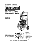
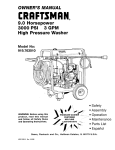
OWNER'S
MANUAL
I:RItFTSMnN
®
6.0 Horsepower
2350 PSI
2.2 GPM
High Pressure Washer
Model No:
919.762350
WARNING:
Before using this
product,
read this manual
and follow
all Safety
Rules
and Operating
Instructions.
•
•
•
•
•
CUSTOMER
HELPLINE
Safety
Assembly
Operation
Maintenance
Parts List
• EspaSol
Sears,
18478
MGP-?62350A
41t/98
Roebuck
and
Co.,
Hoffman
Estates,
IL 60179
U.S.A.
TABLE OF CONTENTS
Warranty
Safety
............................................
Guidelines
..............................
Assembly
..........................................
Operation
..........................................
Maintenance
......................................
2
Service
and Adjustments ................
3-5
Storage
.................................................
5-7
Troubleshooting
7-10
11_13
EPA Codes ......................................
28-29
ON CRAFTSMAN
Parts ...............
Back Cover
...........................................
HIGH
PRESSURE
WASHER
For one year from the date of purchase, when this Craftsman High Pressure Washer is maintained
and operated according to the instructions in the owner's manual, Sears will repair, free of charge,
any defect in material and workmanship.
If your Craftsman Pressure Washer is used for commerical
applies only for 90 days from the date of purchase.
LIMITED
ONE YEAR WARRANTY
ON CRAFTSMAN
or rental purposes, this warranty
ENGINE
Maintenance, replacement or repair of the emission control devices and systems may be performed by any nonroad engine repair establishment or individual. However, to obtain no charge
repairs under the terms and provisions of Craftsman warranty statement, any service or emission
control part repair or replacement must be performed by an factory authorized dealer.
For one year from the date of purchase, when this Craftsman engine is maintained and operated
according to the instructions in the owner's manual, Sears will repair, free of charge, any defect in
material and workmanship.
If your Craftsman engine is used for commerical or rental purposes, this warranty applies only for
90 days from the date of purchase. This warranty does not cover: Expendable items such as
spark plugs and air filters, which become worn during normal use.
Repairs necessary because of operator abuse or negligence, including damage resulting from no
water being supplied to pump or failure to maintain the equipment according to the instructions
contained in the owner's manual, are not covered under warranty.
WARRANTY SERVICE IS AVAILABLE BY RETURNING THE HIGH PRESSURE WASHER TO THE
NEAREST SEARS SERVICE CENTER/DEPARTMENT THROUGHOUT THE UNITED STATES.
This, warranty gives you specific legal rights and you may also have other rights, which vary from
state to state.
Sears,
Roebuck
15
16-27
Espa5ol
ONE YEAR WARRANTY
14
Parts ................................................
How to Order
LIMITED
....................................
13-14
and Co., D/817 WA, Hoffman
Estates,
IL 60179
iiiiii
34-51
SAFETY
GUIDELINES
- DEFINITIONS
This manual containsinformationthat is importantfor you to know and understand. This informationrelatesto protesting
YOUR SAFETYand PREVENTING EQUIPMENT PROBLEMS. To helpyou recognizethis information,we usethe symbols
below. Pleaseread the manualand pay attentionto thesesections.SAVETHESE DEFINITIONS/INSTRUCTIONS.
•& WARNING indicates a potentially hazardous
situation which, if not avoided, _could result in
death or set ous in"
,
CAUTION indicates a potentially hazardous situation
which, if not avoided, _
result in minor or moderate
A DANGER indicates an imminently hazardous
situation which, if not avoided, will result in
death or serious injury.
i__qju .
f_2_Z
IMPORTANT
SAFETY
INSTRUCTIONS
!'_YI:! I]_ I1_[e]
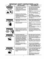
Improper operation or maintenance of this product could result in serious injury and property damage. Read
and understand all warnings and operating instrucUons before using.
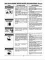
HAZARD
RISK OF EXPLOSION
OR FIRE
WHAT CAN HAPPEN
HOW TO PREVENT IT
• Spilled gasoline and its vapors can
become ignited from cigarette
sparks, electrical arcing, exhaust
gases, and hot engine components
such as the muffler.
• Shut off engine and allow it to cool
before adding fuel to the tank.
• Heat will expand fuel in the tank
which could result in spillage and
possible fire explosion.
• Use care in filling tank to avoid
spilling fuel. Move pressure washer
away from fueling area before
starting engine.
• Keep maximum fuel level 1/2"below
top of tank to allow for expansion.
Operating the pressure washer in an
explosive environment could result
in a fire.
Materials placed against or near the
pressure washer can interfere with
its proper ventilation features
causing overheating and possible
ignition of the materials.
Improperly stored fuel could lead to
accidental ignition. Fuel improperly
secured could get into the hands of
children or other unqualified persons.
,, Operate and fuel equipment in well
ventilated areas free from obstructions. Equip areas with fire
extinguishers suitable for gasoline
fires.
• Never operate pressure washer in an
area containing dry brush or weeds.
Store fuel in container approved for
gasoline, in a secure location away
from work area.
Breathing exhaust fumes will cause
serious injury or death.
• Operate pressure washer in a well
ventilated area. Avoid enclosed areas
such as garages, basements ,etc.
• Never operate unit in a location
occupied by humans or animals.
Some cleaning fluids contain substances which could cause injury to
skin, eyes, or lungs.
Use only cleaning fluids specifically
recommended for high pressure
washers. Follow manufacturers
recommendations.
RISK TO BREATHING
IMPORTANT
HAZARD
SAFETY
INSTRUCTIONS
WHAT CAN HAPPEN
RISK OF UNSAFE
OPERATION
RISK OF INJURY FROM
SPRAY
ELECTRICAL
SHOCK
RISK
OF
RISK OF FLUID INJECTION
HOW TO PREVENT IT
• Unsafe operation of your pressure
washer could lead to serious injury
or death to you or others.
• The spray gun/wand is a powerful
cleaning tool that could look like a
toy to a child.
• Become famiUar with the operation
and controls of the pressure washer.
• Keep children away from the
pressure washer at all times.
• Never defeat the safety features of this
product.
• Do not operate machine with missing,
broken, or unauthorized parts.
• Reactive force of spray will cause
gun/wand to move, and could cause
the operator to slip or fall, or
misdirect the spray. Improper control
of gun/wand can result in injuries to
self and others.
• Never leave wand unattended while
unit is running.
• Keep work area free of obstacles.
• Stand on a stable surface and grip gun/
wand firmly. Expect the gun to kick
when triggered.
High velocity fluid spray can cause
objects to break, propelling particles
at high speed.
• Always wear ANSI approved Z87 safety
glasses. Wear protective clothing to
protect against accidental spraying.
Ught or unsecured objects can become
hazardous projectiles.
• Never point wand at, or spray people or
animals.
• Always secure trigger lock when wand
is not in service to prevent accidental
operation.
• Never permanentlysecuretrigger
inpull
back (open)position.
• Spray directed at electrical outlets or
switches, or objects connected to an
electrical circuit, could resultin a fatal
electrical shock.
• Unplug any electrically operated
product before attempting to clean it.
Direct spray away from electric outlets
and switches.
• Your washer operates at fluid
pressures and velocities high enough
to penetrate human and animal flesh,
which could result in amputation or
other serious injury. Leaks caused by
loose fittings or worn or damaged
hoses can result in injection injuries.
DO NOT TREAT FLUID iNJECTION AS
A SIMPLE CUT! See a physician
immediately!
• Never place hands in front of nozzle.
• Direct spray away from self and others.
• Make sure hose and fittings are
tightened and in good condition. Never
hold onto the hose or fittings during
operation.
• Do not allow hose to contact muffler.
• Never attach or remove wand or hose
fittings while system is pressurized.
• Relieve system pressure before
attempting maintenance or disassembly of equipment.
RISK OF CHEMICAL
BURN
(cont'd)
Use of acids, toxic or corrosive
chemicals, poisons, insecticides, or
any kind of flammable solvent with this
product could result in serious injury
or death.
Use only hose and high pressure
accessories rated for 2000 PSI service.
To relieve system pressure, shut off
engine, turn off water supply, and pull
gun trigger until water stops flowing.
i •
Do not use acids, gasoline, kerosene, or
any other flammable matarials in this
product. Use only household
detergents, cleaners and degreasers
recommended for use in pressure
washers.
• Wear protective clothing to protect
eyes and skin from contact with
sprayed materials.
IMPORTANT
SAFETY
INSTRUCTIONS
(cont'd)
HAZARD
WHAT CAN HAPPEN
HOW TO PREVENT IT
RISK OF HOT SURFACES
* Contact with hot surfaces, such as
engines exhaust components, could
result in serious burn.
• During operation, touch only the control
surfaces of the pressure washer. Keep
children away from the pressure washer
at all times. They may not be able to
recognize the hazards of this product.
Symbols
Owner's
Manual
I_e_I Choke
IMPORTANT:
The powerful spray from your pressure washer is capable of causing damage to fragile surfaces such as: wood, glass,
automobile paint, auto stripping and trim, and delicate objects such as flowers and shrubs. Before spraying, check the
item to be cleaned to assure yourself that it is robust enough to resist damage from the force of the spray. Avoid the
use of the concentrated spray stream except for very strong surfaces like concrete and steel.
Operating unit with water supply shut off without flow of water will result in equipment damage. You should never run
this pressure washer for more than 2 minutes without pulling the trigger to allow cool water to enter the pump and the
heated (recirculated) water to exit. Running the pressure washer with water supply shut off will void your warranty.
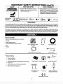
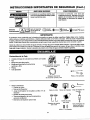
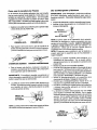
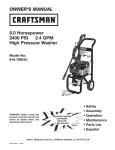
Carton
Contents
O
• Main Unit pressure washer with wheels
• Handle
• High Pressure Hose
• Chemical Pickup Hose and Filter
• Gun
Main Unit pressure washer
with wheels
Handle
High Pressure Hose
©
• Wand
Chemical
Pickup Hose and Filter
Gun and Wand
Video Cassette
Nozzle Cleaning Kit
• Bag Containing
•
Video Cassette
•
Owners' Manual
•
•
Nozzle Cleaning Kit and Replacement O-Rings
Engine Oil
•
Rubber Isolator and Mounting Hardware
•
Handle Mounting Hardware
Owners'Manual
3:
LL
Handle Mounting
Hardware
t
Engine Oil
0@
Replacement O-Rings
5
@
<3E_
Rubber Isolator and
Mounting Hardware
Tools Required for Assembly
Adjustable
wrench
Allenwrench 5ram (included)
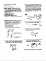
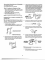
Remove
Pressure
Washer
from
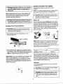
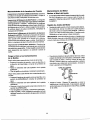
3. • Mount the rubber isolator to the frame. To mount
isolator place threaded end of bolt through the
washer. Next with washer on boIt place threaded
end of bolt through the larger hole in bottom of the
rubber isolator. Place threaded portion of bolt
through the same hole location the wood plank
was mounted to on the pressure washer. Next
place the tee nut over the threaded portion of the
bolt and use the allen wrench provided to tighten
isolator to the frame.
Carton
• Open box from the top. Locate and remove from
box, the parts box, which includes gun, handle,
wand,oil, knobs and J bolts. Next remove the parts
bag and the handle.
• Cut carton along dotted lines.
• Remove all carton inserts.
WASHe.
I
• Roll unit through opening in Carton,
L
NOTE: The hose is located at the bottom of the box,
PRESSURE
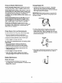
Preparing
the Pressure
Washer
J
--
TEE NUT
ISOLATOR
for First Use
Note: Included with your pressure washer is a
video cassette tape on how to prepare your unit
for operation. It is recommended you view this
tape before performing the next steps,
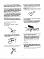
4. • Connect wand extension to gun. To tighten, turn
knob in clockwise direction. Hand tighten.
1. • Insert handle onto frame.
• Slide J bolts into frame.
• Tighten knobs turning in clockwise direction.
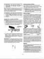
5. =Remove tie wrap off of high pressure hose.
Unwind high pressure hose and attach the
threaded end to the gun.
!ir
lghten
knob in clockwise
ctinn to threaded
_9oes
end of J bob+)
(inzert J bolt Itere, Th,,,_zdedend
in bOt_m hole)
6. • Connect high pressure hose to outlet on pressure
washer and hand tighten firmly. Connect
chemical pickup hose to hose barb on pump.
2. =Using an adjustable wrench, remove nut from bolt
that attaches board to frame. Remove wood plank
from the frame of the unit. Discard bolt and board.
CHEMICAL-'--'---_k-_
II
HOSE
NOTE: Always keep hose away from engine muffler.
6
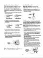
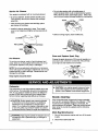
7.
• Place assembled gun and wand on pressure
washer holder.
- Lift the pull cord handle up and slide the cord to
the left sliding the cord into the wire loop.
- Next slide handle behind the wire bracket to the
left of the wire loop.
- Engine recoil will pull the cord into its final
position.
Checklist
Before going any further please review the following:
• Be sure you have completed assembly instructions.
• Double check all fittings to be sure they are tight.
8. • Place pull cord into the wire bracket holder.
- Pull the cord under the wire bracket to the right
of the wire loop.
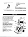
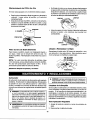
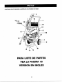
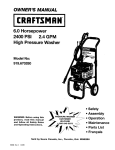
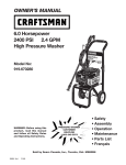
Know Your High Pressure
IMPORTANT: Before any attempt to start your pressure washer be sure to check engine oil (See Operation
under Engine Oil, page 8.)
Washer
GUNWAND
Read this Owner's Manual and Safety Rules
before operation of your High Pressure Washer
Compare this illustration with our pressure washer
to familiarize yourself with the location of various
controls and adjustments. Save this manual for
future reference.
PUMP- Develops high pressure.
HOSE
PRESSURE REGULATOR- Allows you to adjust the
pressure of the outlet stream.
ENGINE RUN/STOP LEVER- Sets engine in starting
mode for recoil starter -- Stops running engine.
GAS
RECOIL
RECOIL STARTER- Used for starting the engine
manually.
SPRAY GUN ASSEMBLY- Controls the application of
water onto cleaning surface with trigger device.
OIL FILL- Port where engine ell is poured.
CHOKE
GAS TANK/CAP- Cap is removed and unleaded
gasoline is poured.
CHEMICAL INJECTION TUBE AND FILTER- Mixes
water and detergent in outlet water flow.
HIGH PRESSURE OUTLET- Connection for high
pressure hose.
CHOKE- Lever used for starting unit.
HOSE
WATER INLET
REGULATOR
HIGH PRESSURE
OUTLET
_,
BEFORE
arning: Read Owner's Manual. Do not attempt
to operate equipment until you have read Owners
Manual for Safety, Operation, and Maintenance
Instructions.
STARTING
NOTE: Your pressure washer pump is a sealed pump
you should never have to add or change the oil
wa eve
eore
eI e
every start. Running engine low of oil or out of oil
could result in serious damage.
,,,,
_, Warning: Never adjust spray pattern when spray- I
ing. Never put hands in front of spray nozzle to
|
adjust spray pattern because you could be injured t
Your Pressure
Washer
I
_, CAUTION: Do not run pump without the water
supply connected and turned on, Failure to do so
will result in pump damage.
ENGINE
To operate the engine you will need to do the
following.
Note: Included with your unit is a video cassette that
demonstrates how to operate your pressure washer.
If you have a video cassette recorder you should
view the video before operation.
Stopping
THE
J
I
Engine
Oil
Your unit has been shipped without oil in the engine.
A bottle of SAE 30 weight oil is included in the carton.
Remove oil dip stick located on top of the engine. Oil
capacity is about 20 ounces of oil. The oil dip stick is
clearly marked with a line that tells you when unit has
enough oil. To check oil, place dipstick into oil fill.
Tighten dipstick then remove.Do not fill above this
point. Pour slowly.
• Move threttle control to the stop position to turn
pressure washer off.
THROTTLE
CONTROL
NOTE: When adding oil to the engine crankcase, use
a high quality detergent oil classified for Service SF,,
SG, SH, rated SAE 30 weight. Use no special additives. Select the oil's viscosity grade according to your
expected operating temperatures.
• Simply shutting OFF engine will not release pressure
in the system. After engine has stopped, squeeze the
trigger on the spray gun for about 3 seconds to relieve
pressure. Spray stream will decrease in length.
IMPORTANT: This unit is equipped with a thermal relief
valve. If unit is allowed to run for several minutes
without pressing the trigger on the spray gun, several
drops of water may be released through this valve to
cool the unit. The heated water will be purged from the
bottom of the pump.
colder <......
Synthetic 5W-30
-------4O°F
I
> warmer
SAE 30
Although multi-viscosity oils (5W30, 10W30, etc.)
improve starting in cold weather, these multi-viscosity
oils will result in increased oil consumption when used
above 40°F Check your engine oil level more frequently
to avoid possible damage from running low on oil, Oil
sump capacity is about 20 ounces.
Gasoline
Your pressure washer engine is 4 cycle. Use fresh
unleaded fuel only.
_,
allow room for fuel expansion.
AUTION: Do not overfill the fuel tank. Always
_. WARNING; Never fill fueI tank indoors. Never
fill fuel tank when engine is running or hot, Do
not smoke or have open flame when tilting fuel
tank.
,I
k
Use clean, fresh, regular unleaded gasoline with a
minimum of 85 octane. Do not mix oil with gasoline. If
unleaded fuel is unavailable leaded fuel may be used.
IMPORTANT: It is important to prevent gum deposits
from forming in essential fuel system parts such as the
carburetor, fuel filter hose or tank during storage. Also,
experience indicates that alcohol-blended fuels (called
gasohol or using ethanol or methanol) can attract
moisture which leads to separation and formation of
acids during storage. Acidic gas can damage the fuel
system of an engine while in storage. To avoid engine
problems, the fuel system should be emptied before
storage of 30 days or longer. Never use engine or
carburetor cleaner products in the fuel tank or permanent damage may occur.
• Squeeze trigger on pressure washer wand to relieve
air pressure caused by turning on the water. Water
will spew out of the gun in a thin stream. This will
make it easier to start the engine.
• Engage the safety latch on the spray gun. This locks
the trigger in place and keeps you from accidentally
spraying a high pressure stream.
_LA
AFETY
TCH
NOTE: Never start pressure washer without water
source turned on and connected to pressure washer.
• On the engine there is a choke/run lever. Place lever
to the choke position.
To Start
• On the engine there is a throttle control lever. Place
throttle to the rabbit position. Always start engine
with throttle in the rabbit (high speed) position.
Your Pressure
Washer
• Remove gas cap
• Add unleaded gasoline, slowIy, to fuel tank.
• Do not overfill.
CHOKE
• Connect garden hose to the water inlet on the
pressure washer. Tighten by turning water inlet
counter clockwise.
• Grasp the starter grip and pull slowly until resistance
is felt;, then pull firmly to start engine.
NOTE: If engine does not start right away, squeeze
the trigger on the gun to relieve water pressure
caused by turning on the water. Water will spew
out of the gun in a thin stream. This will make it
easier to pull start the engine. If more than five
pulls are required, place choke lever back to run
position.
• When engine starts, gradually move choke lever to
RUN position.
• Connect high pressure hose to discharge on pump.
• Connect the garden hose to the water spout
and turn water supply on.
• For hot engine restarts, make sure throttle is in the
rabbit (High speed) position and the choke lever is in
the RUN position.
• Grasp the starter grip and pull slowly until resistance
is felt; then pull firmly to start engine.
How
To Use Your Pressure
Washer
On the end of your spray gun is a nozzle that you can
slide forward and backward and that you can also
twist from side to side. With the adjustable nozzle you
can adjust the spray pattern to either high pressure
or low pressure. You can also adjust the spray so it is
concentrated in a stream pattern or expanded into a fan
pattem.
Using
Soaps/Chemicals
IMPORTANT: Use soaps and chemicals that are
designed specifically for use with pressure washers. To
apply soaps/chemicals follow these steps:
• Prepal;e'the soap/chemical
as required by your job.
• Insert soap/chemical line into your container (soap/
chemicals not included).
• Slide the nozzle forward for low pressure. Pull nozzle
back for high pressure.
C. AL
CHEMICAL
HIGH PRESSURE
LOW PRESSURE
• To adjust your spray pattern twist the nozzle
clockwise for fan spray or counterclockwise for
stream spray.
JUG_
_._
NOTE: The first step involves applying an appropriate
soap/chemical solution to penetrate and loosen grime.
ADDIV the solution at low pressure to avoid splashing,
over spray and waste. Leave the solution on surface for
3to 5 minutes to allow solution to work.
NOTE: The second step involves cleaning the surface
you have prepared with the pressure washer and then
rinsing it clean.
FAN SPRAY
STREAM SPRAY
• Slide the adjustable nozzle forward to low pressure
mode. Soap/chemicals cannot be applied with nozzle
in high pressure position.
• Review the use of the adjustable nozzle.
• For most effective cleaning, keep spray nozzle
between 8 and 24 inches from cleaning surface.
• Connect garden hose to water inlet (see "ToStart Your
Pressure Washer"). Check that high pressure hose is
connected to spray gun and pump (see Assembly),
and start engine.
IMPORTANT" If you get spray nozzle too close,
especially on high pressure, you may damage the
surface you are cleaning.
• The pressure control knob is located on the pump.
You can increase the pressure by turning the knob
clockwise or decrease the pressure by turning the
knob counterclockwise.
• Apply soap/chemicals to dry surface, starting from the
bottom and working up.
• Allow the soap/chemicals to soak in between 3-5
minutes before washing and dnsing.
• For cleaning, start at lower portion of area to be
washed and work upward, using long, even overlapping strokes.
• Your pressure washer is equipped with a chemical
injector adjustment knob. With the knob fully opened
you will get a maximum chemical draw. With knob
fully closed you will get no chemical draw. Turn
knob in counter clockwise direction to achieve more
chemical draw and clockwise for less chemical draw,
PRESSURE
CONTROL
KNOB
NOTE: The maximum pressure for the unit is set at it's
maximum setting at the factory. Do not attempt to adjust
the pressure higher than this factory setting.
CHEMICAL
INJECTOR
ADJUSTMENT
KNOB
10
• Afterusingthe
pressure washer, you should flush
the pump, chemical injector and chemical line with
CUSTC)MER _BlUTIES
MAi_
clear water° To do so, simply place chemical injector
hose in water and siphon for 1 to 2 minutes.
TABLE
Every25
Beforeeachuse hoLrscr yeady
TASK
Every50
lhours
oryearly
Every 100
hoursoryeady
PRESSURE
WASHER
Checlddean inletscreer_
x
Check
p ssurehose.
X
Checksoapandchernic_hoseand filter
x
Check gun and wand for le_s.
x
PurgepLrnpof ar andcor_arrinants
X
ENGINE
Chag_ engine
oil
x
Se_ice airdeener
x
aearVreplace
sparkplug
Product
x
Specifications
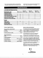
Pressure Washer Specifications
Pressure
Flow Rate
Cleaning Units (psi x GPM)
General
2350
2.2 GPM
5170
The warranty of the high pressure washer does not
cover items that have been subjected to operator
abuse or negligence. To receive full value from the
warranty, operator must maintain high pressure
washer as instructed in this manual.
I
Some adjustments will need to be made periodocally to maintain your high pressure washer.
Engine Specifications
RPM
Rated Horsepower
Spark Plug Gap
Gasoline Capacity
Oil (22 oz. capacity)
Recommendations
All adjustments in the Maintenance section of this
manual should be made at least once each season.
3600
6.0
Once a year you should clean or replace the spark
plug, and clean or replace the air filter, and check
the gun and wand assembly for wear. A clean spark
plug and clean air filter assure proper fuel-air mixture
and help your engine run better and last longer.
".030" (0.76mm)
1.5 quarts
SAE 30 weight
Your pressure washer pump is a sealed pump, you
should never have to add or change the oil.
NOTE: Over time the o-rings in the gun assembly
become worn. Attached to your owners manual is a
replacememt o-ring and split backup o-ring.
11
Pressure
Washer
Maintenance
Change
Check and Clean Inlet Soreen: Examine inlet screen
on pump inlet fitting. Clean if clogged; replace if torn.
Engine
Oil
• Change oll w_lle engine is still warm. Preferably
drain oil from top of engine as illustrated below.
Drain oil with air cleaner side up. Oil can be drained
from engine bottom if necessary.
Check High Pressure Hose: High pressure hose can
develop leaks from wear, kinking, abuse. Inspect hose
each time before use. Check for cuts, leaks, abrasions
or bulging of cover, and damage or movement of
couplings. If any of these conditions exist, replace hose
immediately.
IMPORTANT: Before tipping engine or equipment to
drain oil, drain fuel from tank by running engine until
fuel tank is empty.
Check Chemical/Soap Hose and Air Filter: Examine
the chemical/soap hose and clean if clogged. Hose
should fit'tightly on pump fitting. Check for leaks and
tears. Replace filter or hose if either is damaged.
AIR CLEANER
Check Gun and Wand for Leaks: Examine hose
connection to gun making sure it is secure. Test trigger
by pressing it and making sure it springs back into
place when you release it.
Purge
Pump
• To drain oil from bottom of engine, remove drain
plug as illustrated below. Allow oil to drain and
replace drain plug. Remove dipstick and refill with
new oil of recommended grade. Start and run engine
at idle for 30 seconds.
of Air and Contaminants
To remove the air from the pump, follow these steps:
• Set up the pressure washer as described in
Assembly section and connect the water supply.
OIL DRAIN
PLUG
• Remove the wand extension from the spray gun.
• Pull the trigger on the gun and hold.
To remove the contaminants
these steps:
from the pump, follow
_8"SQUARE
• Set up the pressure washer as described in
ASSEMBLY section, connect the water supply.
• Remove the wand extension from the spray gun.
PIPE
• Start the engine according to instructions in the
OPERATION section.
• Stop engine. Wait 30 seconds and re-check oil level.
If required, add oil to bring level to FULL mark on
dipstick.
• Pull the trigger on the gun and hold.
• When the water supply is steady and constant,
disengage trigger and refasten the wand extension.
Engine
Check
Maintenance
Oil Level
• Oil level should be checked prior to each use
or at least every 5 hours of operation. To check oil see
Engine Oil on page 9.
12
Service
Air Cleaner
• Do not clean engine with a forceful spray of
water because water could contaminate fuel system.
With a brush or cloth, clean finger guard after every
use to prevent engine damage caused by overheating.
Your engine is equipped with an oval dual element.
• To service element: loosen screws and lift cover.
Then carefully remove pre-cleaner and cartridge
assembly.
CLEAN
• After servicing pre-cleaner and cartridge, place
pre-cleaner on cartridge.
CLEAN_
• Install air cleaner assembly in base. Then install
cover on air cleaner and tighten screws securely to
base.
• Before running engine, clean muffler area.
sc-s Z
PRE-CLEANER _
CARTRIDGE
CLEAN
Clean
Pre-Cleaner
and Replace
Spark
Plug
Change the spark plug every 100 hours of operation or
once each year, whichever comes first. This will help
your engine to start easier and run better.
To service pre-cleaner, wash in liquid detergent and
water. Allow to dry thoroughly before using. Do not oil
pre-cleaner. Replace if very dirty or damaged.
.030" (0,76 MM)
WIRE GAGE
NOTE: Do not use petroleum solvents, e.g., kerosene,
which will cause the cartridge to deteriorate. Do not use
pressurized air to clean cartridge. Pressurized air can
damage the cartridge.
Keep engine and parts cleanl
RESISTOR
Carburetor
I
• , CAUTION: Low engine speeds impose a heavy
load on the engine and when sufficient engine
power is not available could shorten engine life.
The carburetor of your high pressure washer is pre-set
at the factory. The carburetor should not be tampered
with. If your pressure washer is used at an altitude in
excess of 5000 feet consult with your nearest Sears
Service Center regarding high altitude set changes.
Nozzle cleaning:
If the nozzle becomes clogged with foreign materials,
such as dirt, excessive pressure may develop. If the
nozzle becomes partially clogged or restricted, the
pump pressure will pulsate. Clean the nozzle immediately using the nozzle kit supplied and the following
instructions:
_, CAUTION: Engine speed was properly adjusted
at the factory and should require no additional
adjustment. Do not attempt to change engine
speed. If you believe the engine is running too fast
or too slow, take your pressure washer to a Sears
Authorized Service Center for repair and adjustment.
Multi-Reg
Wand/Lance:
1. Shut off the pressure washer and turn off the water
supply.
increase the risk of personal injury or damage to
I A WARNING:
equipment, High engine speeds are dangerous and
2. Disconnect spark plug wire.
13
I
I
3.
9. Reconnect wand/lance to gun and turn on water
supply.
Pull trigger on gun handle to relieve any water
pressure.
10. Start pressure washer and place wand/lance
high pressure setting to test.
4. Disconnect the wand/lance from the gun.
5. Remove the nozzle from the end of the wand with
the 2mm allen wrench provided.
6. Clean the nozzle using the nozzle cleaner provided or
a straightened paper clip. Insert into the nozzle end
and work back and forth until obstruction is
removed.
into
(_---,==-
7. Direct water supply into nozzle end to backflush
loosened particles for 30 seconds.
8. Reassemble the nozzle to the wand. Tighten
securely to prevent leaks.
IMPORTANT: It is important to prevent gum deposits
form forming in essential fuel system parts such as the
carburetor, fuel filter hose or tank during storage. Also,
experience indicates that alcohol-blended fuels (called
gasohol or using ethanol or methanol) can attract moisture which leads to separation and formation of acids
during storage. Acidic gas can damage the fuel system
of an engine while in storage. To avoid engine problems,
the fuel system should be emptied before storage of 30
days or longer. Never use engine or carburetor cleaner
products in the fuel tank or permanent damage may
This pressure washer should be stored in such a way to
protect it from freezing. Do not store this unit outdoors
or in an area where temperatures will fail below 32 ° F.
This can cause extensive damage to this unit.
If unit has to be stored under freezing conditions a nontoxic R.V. anti-freeze can be used to protect from
freezing.
Preparing
Pressure
Washer
for Storage
Occur,
NOTE: If you do not plan to use your unit for 30 days or
more, unit should be prepared for storage.
Pump
Engine
Preparation
• Be sure engine switch is in "OFF" position and spark
plug wire has been removed from spark plug.
Preparation
• First add a fuel stabilizer to the fuel tank.
• Pull the trigger on the spray gun to release the
pressure in the high pressure hose. Detach high
pressure hose and garden hose from the unit.
• Run pressure washer for a full 5 minutes to a!low fuel
stabilizer to enter the fuel system.
• Pull the recoil on the engine 4 to 6 times to discharge
remaining water in pump.
NOTE: While doing this procedure make sure water
supply is turned on and flowing to the unit. NEVER run
unit without water supply running through pump.
• Tip the unit on the end with the water inlet fitting
pointing upward.
• Next shut off engine and disconnect the water supply.
• If unit will be stored where temperatures fall below
32°F, pour approximately 1/4 cup of non-toxic R.V.
anti-freeze down the fitting where the water hose
attaches to the pump.
• Disconnect the spark plug wire and remove the spark
plug.
• Add one teaspoon of oil through the spark plug hole.
• Set unit upright and pull starter handle on engine 4 to
6 times to circulate anti-freeze in pump until antifreeze is discharged from the pump.
• Place rag over spark plug hole and pull the recoil a
few times to lubricate the combustion chamber.
• Replace the spark plug, but do not connect the spark
plug wire.
14
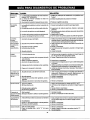
SYMPTOM
CAUSE
SOLUTION
Engine won't
start
1. Engine throttle is in "OFF" Position.
2. Choke lever has not been placed to
choke.
3. Pressure buildup after initialuse.
1. Slide throttle to "Rabbit" position,
2. Slide choke lever to choke position.
1. Nozzle not in chemical draw position.
2. Chemical screen is obstructed.
3. Chemical screen not working.
1. Place nozzlsto low pressure_
2. Check chemical screen; clean if obstructed.
3. Make sure chemical screen is submerged in
chemical/water.
4. Check and clean.
Won't Draw
Chemical
4. Chemical injector orifice obstructed
or stuck.
5. Chemical injector closed.
Pump running
normally but
pressure does
not achieve
rated values
1.
Water supply restricted.
2.
Nozzle is in low PSI pos_lan,
Nozzle incorrector worn.
4. Pump sucking air.
5. Nozzle blocked.
1.
Pump sucking air.
Garden hose inlet strainer clogged.
3. Worn Seals or Packing,
4. Inadequate water supply.
5. Fouled or dirty inlet or discharge
2.
valves.
Pressure drops
after period of
normal use
Pump noisy
Presence
of
water in oil (oil
milky).
Water dripping
from pump
Oil Dripping
5. Open chemical injectorby turning adjustment
knob.
1. Check water supply and filter screen for.
blockage. Check hoses for blockage, kinks,
leaks, etc.
2. Pull nozzle at end of wand back to the high pressure
position.
3. Check and replace.
4. Check that hoses and fittings ere air-tight.
5. Clean nozzle.
3.
Fluctuating
Pressure
3. Depress trigger gun.
6.
Leaky discharge hose.
1,
Nozzle clogged, partially obstructed.
1. Check that hoses and fittings are air tight. Purge air
from garden hose.
2. Clean. Check filter frequently.
3. Check end replace.
4. Check hose for kinks.
5. Check flow availableto pump. Check for
excessive heat, 145o F or above,
6. Clean inlet and discharge valve assemblies,
Replace if damaged.
2.
Nozzle wom.
3. Pump Valves worn, dirty or stuck.
4. Worn pump piston packing.
1. Use nozzle cleaningkit to clear obstruction.(See
Nozzle Maintenance under Service Adjustment.)
2. Clean or replace.
3. Check and replace.
4. Check and replace.
1.
Water too hot.
2. Pump sucking air.
3. Valves dirty or worn.
4. Worn bearings.
1.
2.
3.
4.
High humidity.
2. Piston packing and oil seal worn.
1. Change Oil.
2. Check and replace oil seals.
Thermal relief functioning normal.
2. Fittings Loose.
3, O-rings of piston guide or retainer
worn.
4.
Piston packing worn.
1. Protecting pump, if not using pressure washer for
a long period of time, shutoffengine.
2. Tighten.
3. Check and replace.
4. Check and replace.
1. Oil sealworn
2. Loose drain plugor worn drain plug
o-dng.
1. Check and replace
2. Tighten drainplug or replaceO-ring. Do notovertorque.
1.
1.
15
Reduce temperature below 63° C or 145° F.
Check that hoses and fittings are air tight.
Check, clean or replace.
Check and replace if necessary.
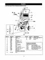
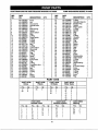
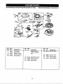
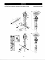
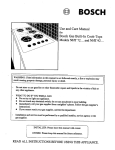
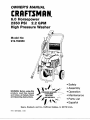
CRAFTSMAN 2350 PSi HIGH PRESSURE WASHER 919362350
16
11
900
I
5
22
20
21
REF NO.
1
2
3
4
5
6
7
6
10
!1
12
13
14
15
16
18
9O0
2O
PART NO.
16469
16471
16468
16466
W137
"t6371
W131
16462
H140
16491
16467
16479
F064
16470
16726
16830
PK16482
DESCRIPTION
REF NO.
PART NO.
DESCRIPTION
Handle
21
16829
Garden Hose Adapter 1/2"
Knob - 5/16"
22
F504W
3/8" Coupling
Gun
23
Fl12
Washer
Tire Semi (7 x I 3/4)
Nut Pal 1/2"
Foot Rubber, Hollow
Tee Nut 5/160" x 3/4"
PART_, NOT ILLUSTRATED
Frame
Hose, Chemical
MGP-762350A Owner's Manual
Lance, Multi-Reg
NCT001
Nozzle Cleaning Kit
Hose
F101
Screw, Hex-Engine to Pump
Decal - Craftsman
F196
Screw, Hex-Engine to Pump
Screw-Hex 5/16" - 18 x 1LG
16087
Nut Flanghead-Engine to Pump
J Bolt 5/16" - 18 x 2.5
F074
Washer Flat-Engine to Pump
Decal - Operation
16505
Thermal Relief Valve
O-Ring Kit
Engine-Refer to engtne breakdown (Model 121602-0206-E1)
Pump
16
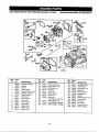
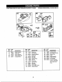
CRAFTSMAN
2350PSlHIGHPRESSURE
WASHER
919.762350
PUMPBREAKDOWN
MODELPK16482
21
.......
J
38
"_.
17
B m
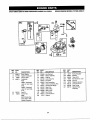
CRAFTSMAN 2350 PSI HIGH PRESSURE WASHER 919.762350
REF.
NO.
PART
NO.
DESCRIPTION
QTY.
PER
NO.
1
2
3
4
5
6
7
8
9
10
11
12
13
14
15
16
17
18
19
20
21
23
24
25
26
27
28
30
31
32
33
34
35
36
AR-1322520
AR-1980300
AR-1980470
AR-1980640
AR-1080070
AR-1980220
AR-1271070
AR-1080041
AR-1080401
AR-1080250
AR-1980210
AR-880830
AR-740290
AR-800560
AR-1271170
AR-1080190
AR-1271160
AR-1980200
AR-1470210
AR-880581
AR-820510
AR-1980310
AR-650530
AR-1980650
AR-1260162
AR-960160
AR-1269050
AR-480480
AR-1250280
AR-1560520
AR-1460430
AR-1540170
AR-1080091
AR-394280
Knob
Nut
Grub screw
Handle insert
Pin
Plate spring
Spring
Upper piston
Ring
O-Ring
Piston guide
O-Ring
O-Ring
O-Ring
Ring
O-Ring
Lower piston
Valve seat
O-Ring
Plug
O-Ring
Screw
Washer
Pump head
Plug
O-Ring
Complete valve
O-Ring
Ball
Spring
O-Ring
Jet
Spring
O-Ring
1
1
1
1
1
1
1
1
1
1
1
7
1
1
1
2
1
1
1
2
2
3
3
1
3
3
6
1
1
1
1
1
1
1
37
38
40
41
42
43
44
45
46
47
48
49
52
53
54
55
56
57
58
59
60
61
62
63
64
65
66
68
70
71
72
73
74
75
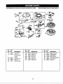
PUMP BREAKDOWN MODEL PK16482
_
PART
NO,
DESCRIPTION
QTY,
AR-1200690
AR-1270130
AR-1980190
AR-1342761
AR-1980180
AR-770130
AR-1260440
AR-1980170
AR-1980410
AR-770090
AR-1980460
AR-1980430
AR-1980290
AR-180030
AR-1980160
AR-1980140
AR-1980150
AR-1980130
AR-1980250
AR-1980240
AR-850370
AR-1980070
AR-1980440
AR-1980340
AR-1980450
AR-1980230
AR-480671
AR-1980510
AR-1200430
AR-1560650
AR-800560
AR-480560
AR-1560670
AR-1560660
O-Ring
Detergent injector
Support ring
Gasket
Piston guide
O-Ring
Gasket
Ring
Seal
O-Ring
Housing
Spacer
Plug
Screw
Spring
Piston
Ring
Rail
Cage
Rail
Screw
Wobble plate
Hollow shaft
O-Ring
Flange
Roller bearing
Seal
El. motor flange
Screw
Hose tail
O-Ring
O-Ring
Knob
Ring
1
1
3
3
3
3
3
3
3
1
1
3
1
4
3
3
3
1
2
3
1
1
1
1
1
1
1
1
4
1
1
1
1
1
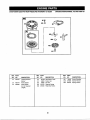
PART KITS
A=KIT 16739
Valves
B=Krr 16740
Pistons
C=KIT 16742
Oil Seals
Pos.
12
28
Pos.
55
Pos.
46
47
66
Qty.
6
6
Qty.
3
1
2
3
4
5
6
7
Qty.
1
1
1
1
1
2
1
Pos,
8
9
10
11
12
13
14
Qty,
1
1
1
1
1
1
1
Qty.
3
1
1
POS.
40
41
43
44
45
49
G=KIT 18741
Chemical Injector
F=KIT t 6737
Unloader Valve
Pos.
D=KIT 16738
Water Seals
Pos,
15
16
17
18
19
Q_y.
Pos.
1
2
1
1
1
30
71
72
73
74
75
18
Qty.
1
1
1
1
1
1
(_y.
3
3
3
3
3
3
H=Krr16743
Bearing
Pos.
Qty,
57
58
59
65
1
2
3
1
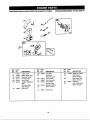
CRAFTSMAN 2350 PSi HiGH PRESSURE WASHER 919.762350
BRIGGS ENGINE MODEL #121602-0206-EI
307
1029
189
REF.
PART
REF.
PART
NO.
NO.
DESCRIPTION
NO.
NO,
DESCRIPTION
NO.
NO.
DESCRIPTION
1
3
5
499678
399269
299819
Cylinder Assembly
Bushing
Seal-Oil
122
155
281617
Spacer-Carburetor
225325
263108
Plate-Cylinder Head
Ball-Rocker Arm
635
7!8
66538
230192
Root-Spark Plug
Dowel-Sleeve
830
499756
Stud-Rocker
6
499643
Head-Cylinder
238
498592
Seal-Valve
273240
Gasket-Cylinder
305
Cap-Valve
Screw-Hex
868
7
253131
94744
883
273348
Gasket-Exhaust
8
9
495786
272481
Breather Assembly
Gaskat-Breether
308
307
225366
94515
Sheitd-Cylinder
Screw-Hex
993
lc,19
273346
499691
Gasket-Plate
Label Kit
10
94955
Screw-Hex
337
499608
Plug-Spark
1022
273241
Gasket-Rocker
1t
13
499675
95049
Tube-Breather
Screw-Hex
354
383
1023
1026
499624
498597
Cover-Rocker
19374
Nut-Has (Sold in Kit Only)
Wrench-Spark Plug
33
499642
Valve-Exhaust
584
34
499641
Valve-intake
555
224328
272238
Cover-Breather Passage
Gasket-Breather
Passage
225246
281621
Arm-Rocker
Guide-Push
35
40
263149
93312
Spring-Valve
Retainer-Valve
1029
1034
1058
273323
Owner's Manual
45
262679
Tappat-Valve
Head
189
REF.
19
PART
Arm
Rod-Push
Rcd
Cover
CRAFTSMAN
2350PSIHIGHPRESSURE
WASHER
919.762350 BRIGGS
ENGINE
MODEL#121602-0206-E1
284 _
24
11si
525
116A_
REF.
PART
NO.
NO.
4
12
499619
272198
15
94880
16
498615
REF.
DESCRIPTION
94220
PART
NO.
NO,
94511
523
499621
495265
24
25
222698
499627
Key-Flywheel
Piston Assembly
Plug-Oil Drain
Crankshaft
Note
26
27
28
499631
263190
499423
Ring Set
Lock-Piston Pin
Pin-Piston
525
562
498612
29
32
499424
94669
Rod-Connecting
Screw-Connecting
43
493737
Governor/Oil
46
499136
Gear-Cam
116
280393
Seal-O-Ring
Crankshaft
Crankshaft
Used on type No(s).
0172.
22
NO.
Sump-Engine
Gasket-Crankcase
498622
399781
REF.
DESCRIPTION
PART
284
Used on Type No(s),
0163.
20
NO.
t16A
280966
Seal-O-Ring
148
227
94388
498772
Key-Timing
Lever-Govemor
Note
230
67072
Washer
(One Used in Hole
Nearest Breather)
20
Rod
Slinger
Seal-Oil
Screw-Hex,
94612 Scraw-Hox.
592
94907
231082
DESCRIPTION
Straw-Shoulder
Dipstick
Tube-OlIFlll
Bolt-Governor
Lever
Nut-Hex,
615
94474
616
263175
Retainer-Governor
Crank-Governor
741
262598
Gear-Timing
847
498715
Dipstick/Tube
Assembly
CRAFTSMAN
2350PSIHIGHPRESSURE
WASHER
919.762350
BRIGGS
ENGINE
MODEL#121602-0206-E1
987_
108
127_
130A 95
REF.
PART
REF.
PART
REF.
PART
NO.
NO.
DESCRIPTION
NO.
NO.
DESCRIPTION
NO.
NO.
51
272487
Gasket-intake
125
499617
Carburetor
137
Gasket-Float
95
94098
163
355
273364
(Sold in Kit Only)
Gasket-Air Cleaner
Washer-Seal
975
987
493640
104
117
124
231371
498978
95048
Screw-Round
Head
127
Pin-Float Hinge
Jet-Main (Standard)
Note
130
224908
(Sold in Kit Only)
Valve-Throttle
131
499682
Shaft-Throttle
498975 Jet-Main
133
398187
Float-Carburetor
(High Altitude)
Screw-Hex.
134
398188
Valve-Needle
Plug-Welch
DESCRIPTION
Bowl
(Sold in Kit Only)
Bowl-Float
Seal-Throttle Shaft
(Sold in Kit Only)
21
CRAFTSMAN
2350 PSI HIGH PRESSURE WASHER 919362350
BRIGGS ENGINE MODEL #121602-0206-E1
534 l
-@
REF.
NO.
51
PART
NO.
272487
95
98
94098
398185
104
108
231371
224783
117A
494870
DESCRIPTION
95048
PART
NO.
NO.
Gasket-Intake
125A
Screw-Round
127
Head
Screw-Idle Speed
Pin-Roat Hinge
Valve-Choke
Jet-Main
Note
(Standard)
497315 Jet-Main
124
REF.
(High Altitude)
Screw-Hex.
499680
DESCRIPTION
REF.
NO.
PART
NO.
Carburetor
Plug-Welch
355
Washer-Seal
(Sold in Kit Only)
Valve-Throttel
633
(Sold in Kit Only)
Seal-Choke Shaft
130A
131
223470
499682
133
398187
Valve-Needle
975
987
134
437
398188
(Includes Seat)
Gasket-Float Bowl
141
499681
273364
DESCRIPTION
163
Float-Carburetor
(Sold in Kit Ordy)
Shaft-Choke
22
493640
Gasket-Air
Cleaner
(Sold in Kit Only)
Bowl-Float
Seat-Throttle
Shaft
(Sold in Kit Only)
CRAFTSMAN
2350PSlHIGHPRESSURE
WASHER
919,762350 ERIGGS
ENGINE
MODEL#121602-0206-E1
REF,
PART
NO.
NO.
DESCRIPTION
REF.
PART
NO,
NO.
R==F. PART
DESCRIPTION
NO.
NO.
DESCRIPTION
642
281620
Cover-Air
Cleaner
966
499684
Base-A/C
primer
967
273356
Filter-Pre-Cleaner
971
976
95103
496115
Screw-Shoulder
Primer-Carburetor
11
499675
Tube-Breather
263226 Spdng-Gov.
51
163
272467
273364
Gasket-Intake
202
261348
Gasket-Air Cleaner
Link-Mechanical Gov,
Used on Type No(s),
0152.
208
263044
Spring-Governor
259
445
224348
498596
Bracket-Casing Clamp
Filter-NC Cartridge
534
620
95059
498706
Screw-Slotted
Bracket-Control
23
CRAFTSMAN
2350PSIHIGHPRESSURE
WASHER
919.762350 BRIGGS
ENGINE
MODEL#121602-0206-E1
__
,,,
,,,,,,.,
, ,,,,,
3os
REF.
NO.
pART
NO.
REF.
PART
DESCRIPTION
NO.
NO.
REF.
PART
DESCRIPTION
NO.
NO,
Guard-Flywheel
305
DESCRIPTION
94744
Screw-Hex,
851
493880
Terminal-Cable
Nut-Flywheel
910
922
94510
262640
Stud-Stator Mounting
Spring=Brake
Brake
37
224511
65
94904
Screw-Hex.
332
94877
73
258
225125
'94512
Screen-Rotating
Screw-Slotted
Hex,
333
334
802574
94731
Armature-Magneto
Screw-Hex.
923
493442
304
499677
Housing-Blower
356
356A
497833
493400
Wire-Stop
Wire-Stop
935
940
499421
499679
Switch-ioterlock
363
373
19069
94908
Flywheel Puller
Nut-Hex.
1005
281657
1036
499343
Fan-Flywheel
Label Kit-Emission
423
93758
Screw-Hex.
455
474
225121
492841
Cup-Flywheel
Alternator
621
727
396847
281675
Switch-Stop
Cover-Starter
789
493379
Harness-Wiring
24
Guard_Ftywheet
Used on Type No(s).
0015, 0100, 0152,
0155.
Drive
CRAFTSMAN
2350PSIHIGHPRESSURE
WASHER
919.762350 BRIGGS
ENGINE
MODEL#121602-0206-E1
REF.
PART
REF.
PART
REF.
PART
NO.
NO.
DESCRIPTION
NO.
NO.
DESCRIPTION
NO,
NO,
DESCRIPTION
153
187
95050
296004
Screw-Phillips
Line-Fuel
300
305
498733
Muffler-Exhaust
(Cut to Required
346
670
676
832
280512
397931
498736
Spacer-Fuel Tank
Deflector-Muffler
Guerd-Muffler
94744
94896
Screw-Hex,
Screw-Hex.
Length)
Line-Fuel
346A
346B
95062
Screw-Hex.
883
273348
Gasket-Exhaust
94874
Screw-Hex.
921
498734
Cover-Blower
346C
94786
Screw-Hex.
298090
Screw-Shoulder
Filter-Fuel
601
93053
Clamp-Hose
987
972
498697
499618
Cap-Fuel Tank
Tank-Fuel
94511
Screw-Shoulder
187A
186
498171
398540
240
284
25
Housing
CRAFTSMAN
2350PSIHIGHPRESSURE
WASHER
919,762350 BRIGGS
ENGINE
MODEL#121602-0206-E1
55
373 _
5
689 0
REF,
PART
REF.
NO,
PART
NO.
REF.
PART
NO.
NO.
DESCRIPTION
NO,
497440
Housing-Rewind
Starter
80
65
281434
94904
Grip-Starter Rope
Screw-Hex.
461
94943
608
497680
Starter-Rewind
Nut-Hex.
689
263073
Spring-Friction
55
NO.
56
498144
Pulley-Starter
373
94908
58
280399
Rope-Starter
456
459
281503
281505
(Cut to Required
DESCRIPTION
Retainer-Spdng
Plate-PauIFriction
Length)
26
DESCRIPTION
Screw-Shoulder
CRAFTSMAN
2350PSIHIGHPRESSURE
WASHER
919.762350 BRIGGS
ENGINE
MODEL#121602-0206-E1
:_S0GASKET SET
883 _-_
116_
116A_
3_20_
978}_"_
51_
9_
163
_
5_O
121 CARBURETOR
1033 VALVE OVERHAUL KIT
KIT
1346
987 0
9560
9'F/CARBURETOR
855
GASI'_
SET
_3_
I
51
I
i
REF. PART
NO. NO.
3
299819
DESCRIPTION
Seal-oil
7
9
273240
272481
Gasket-CyUnder
Gasket-Breather
12
272198
Gasket-Crankcase
20
399781
Seal-Oil
51
272487
Gasket-intake
104
116
231371
290393
Pin-Float Hinge
Seal-O-Ring
116A
280966
121
122
499685
281617
Seal-O-Ring
Carburetor Kit
Spacer-Carburetor
REF.
PART
NO.
NO.
DESCRIPTION
REF. PART
NO, NO.
DESCRIPTION
127
Plug-Welch
633
134
(Sold in Kit Only)
Valve-Needle
868
498592
(Sold in Kit Only)
Seal-Valve
883
273348
Gasket-Exhaust
977
499687
Gasket-Set
Carburetor
273346
Gasket
Head
398188
Seal-Choke Shaft
137
(Includes Seat)
Gasket-Float Bowl
163
(Sold in Kit Only)
Gasket-Air Cleaner
978
355
Washer-Seal
987
358
585
(Sold in Kit Only)
Gasket Set
Gasket-Breather
1022
273241
(Sold in Kit Only)
Gasket-Rocker
Cover
1033
499688
Kit-Valve Overhaul
273364
499686
272238
Passage
27
Seal-Throttle Shaft
BdggS & Stratton Corporation (B&S), the California Air Resources Board (CARB)
and the United States Environmental Pr,otactfon Agency (U.S. EPA)
Emission Control System Warranty Statement (Owner s Defect Warranty Rights and Obligations)
Inthe interestofthe environment,B&Senginas that meet strictemisTO CERTIFIED ENGINES PURCHASED IN CALIFORNIA IN 1995
sionrequlremantsarelabeled,"Thisengineconformsto 1995-1998
AND THEREAFTER, WHICH ARE USED IN CALIFORNIA, AND
California emission regulations for ULGE engines and U.S. EPA
TO CERTIFIED MODEL YEAR 1997 AND LATER ENGINES
Phase I regulationsfor small non-road engines."
WHICH. ARE PURCHASED AND USED ELSEWHERE IN THE
EMISSION CONTROL WARRANTY COVERAGE IS APPUCABLE
UNITED STATES.
California and United State==Emlulon Control Defects Warranty Statement
there has been no sbuse, neglect or impropermaintenance of your
CARB, U.S. EPA and B&S are pleased to explain the Emission
ULGE engine.
ControlSystem Warranty on your 1996and later utilityor lawn and
garden equipment(ULGE) engine. In Calitomia,new ULGE engines
Youremissioncontrolsystem includesparts suchas the carburetor,
produced on or after August t, 1995 must be designed, built and
air cleaner, ignition system, muffler and catalytic conveder. Also
includedmay beconnastorsand other emissionrelatedassemblies.
equipped to meet the State's stringentanti-smog standards,Elsewhere in the United States, new non-road, spark-ige_
engines
Where a warrantable condition exists, B&S will repair your ULGE
certifiedfor modelyear 1997 and later, must meet similarstandards
engine at no cost to you includingdiagnosis, parts and labor.
set forth by the U.S. EPA. B&S must warrant the emissioncontrol
systemon your engine for the periods of time listedbelow,provided
Brfggs & Stratton Emission Control Defects Warranty Coverage
ULGE engines are warranted relative to emission control pads
below, lfanycoveredpadonyourangineisdetective, thepadwi, be
detects for a period of two years_ subject to provisionsset forth
repaired or replaced by B&S.
Owner's Warranty Responsibilities
As the ULGE engine owner,you are responsiblefor the performance
You are responsiblefor presentingyour ULGE engine to an Authodzed B&S Service Dealer as soon as a problem exists. The undisof the requiredmaintenance ]istsd in yourOperator/Owner Manual.
putedwarrantyrepairs should be completed ina reasonebla amount
B&S recommendsthat you retain all yourreceiptscovering mainteof time, not to exceed 30 days.
nance on your ULGE engine, but B&S cannot deny warrantysolely
for the lack ofreceiptsorfor yourfailure toensurethe performanceof
If you have any quastlons regarding your warranty rights and
all scheduledmaintenance.
responsibilities, you shouldcontacta B&S Service Representative
at 1-4! 4-259-5262.
Asthe ULGE engine owner,youshouldhoweverbe aware that B&S
The emissionwarranty isa defects warranty.Defects are judged on
may deny you warranty coverage if your ULGE engine or a part has
normal engine performance. The warrantyis not related to an in-use
failed due to abuse, neglect, impropermaintenance or unapprovod
emission test.
modifications.
Brlggs & Stratton Emission Control Defects Warranty Provisions
The following are specificprovisionsrelativetoyour EmissionControlDefects Warranty Coverage. It is in additiontothe B&S engine warranty
for non-ragulatedengines found in the Operator/Owner Manual.
3. No Charge
1. Warranted Parts
Repair or replacementof any Warranted Part will be performed
Coverage under this warranty extends only to the parts listed
at no chargeto the owner, including diagnostic labor whichleads
below (the emission control systems parts) to the extent these
to the determination that a Warranted Part is defective, if the
parts were present on the engine purchassd.
diagnostic work is performed at an Authorized B&S Service
a. Fuel Metering System
Dealer. For emissions warranty service contact your nearest
•
Cold start enrichment system (serf choke)
Authorized B&S Service Dealer as listed in the "Yellow Pages"
under "Engines, Gasoline," "Gasoline Engines," "Lawn
•
Carburetor and internal pads
Mowers," or similarcategory.
,,
Fuel Pump
4. Claims and Coverage Exclusions
b. Air Induction System
Warranty claims shallbe tiled in accordance with the provisions
•
Air cleaner
of the B&S Engine Warranty Policy. Warranty coverage shall be
excluded for failures of Warranted Parts which are not original
• . Intake manifold
B&S parts or because of abuse, neglect or improper maintec. Ignition System
nance as set forth in the B&S Engine Warranty Policy. B&S is net
•
Spark piog(s)
liable to cover failures of Warranted Parts caused by the use of
add-an, non-or'_ginsi,or modified parts.
•
Magneto ignition system
5. Maintenance
d. Catalyst System
Any Warranted Part which is not scheduledfor replacement as
•
Catalytic converter
required maintenance or which is scheduled only for regular
•
Exhaust manifold
inspectionto the effectof =repair or replace as necessary" shall
be warranted as to defects for the warranty period. Any
•
Air injection system or pulse valve
Warranted Partwhich is scheduledfor replacement as required
e. Miscellaneous Items Used in Above Systems
maintenance shallbe warrantedas to defects onlyfor the period
•
Vacuum, temperature, position,time sensitivevalves
of time up to the first scheduled replacement for that part. Any
and switches
replacementpart thatis equivalentinperformance and durability
•
Connectors and assemblies
may be used in the performanceof any maintenance or repairs.
The owner is responsible for the performance of all required
2. Length of Coverage
maintenance, as defined in the B&S Oparator/Owner Manual.
B&S warrantstothe initia_ownerand each subsequentpurchaser
6. ConsequentialCoverage
that the Warranted Parts shall be free from defects in materials
Coverage hereunder shall extend to the failure of any engine
and workmanship which caused the failure of the Warranted
componentscaused by the failure of any Warranted Part still
Parts for a penod of two years from the date the engine is delivunder warranty.
ered to a retail pumhaser.
28
Briggs& Stratton
welcomes
warranty
repairandapologizes
to you for being inconvenienced. Any Authorized Service
Dealer may perform warrantyrepairs. Most warrantyrepairs
are handled routinely,but sometimes requests for warranty
service may notbe appropriate.For example, warrantywould
notapplyif enginedamage occurredbecause of misuse, lack
of routinemaintenance, shipping,handling,warehousingor
improperinstallation.Similarly,warranty is void if the serial
number of the engine has been removed or the engine has
been altered or modified.
Repair or adjustment of associated parts or assemblies
such as clutches, transmissions, remote controls, etc.,
which are not manufactured by Briggs & Stratton.
6. Damage or wear to parts caused by dirt, which entered
the engine because of improper air cleaner maintenance,
re-assembly, or use of a non-odginsl air cleaner element
or cartridge. (At recommended intervals, clean and re-oil
the Oil-Foam® element or the foam pre-cleaner, and
replace the cartridge.) Read "Owner's Manual."
7. Parts damaged by overspeeding, or overheating caused
by grass, debris, or dirt. which plugs or clogs the cooling
fins, or flywheel area, or damage caused by operating the
engine in a confined area without sufficient ventilation.
(Clean fins on the cylinder, cylinder head and flywheel at
recommended intervals.) Read "Owner's Manuel."
Improper maintenance:
The life of an engine depends upon the conditionsunder
whichit operates,and the care itreceives.Some applications,
such as tillers,pumpsand rotarymowers, arevery oftenused
in dusty or dirtyconditions,whichcan cause what appears to
be premature wear. Such wear, when caused by dirt, dust,
spark plug cleaning grit, or other abrasive material that has
entered the engine because of impropermaintenance, is not
covered by warranty.
8.
Engine or equipment parts broken by excessive vibration
caused by a loose engine mounting, loose cutter blades,
unbalanced blades or loose or unbalanced impellers,
improper attachment of equipment to engine crankshaft,
overspeeding or other abuse in operation.
9.
A bent or broken crankshaft, caused by striking a solid
object with the cutter blade of a rotary lawn mower, or
excessive v-belt tightness.
10, Routine tune-up or adjustment of the engine.
11. Engine or engine component failure, i.e, combustion
chamber, valves, valve seats, valve guides, or burned
starter motor windings, caused by the use of alternate
fuels such as, liquified petroleum, natural gas, altered
gasolines, etc.
This warranty covers engine related defective material
and/or workmanship _
and not replacement or refund
of the equipment to which the engine may be mounted.
Nor does the warranty extend to repairs required
because of:
ARE
Parts which are scored or broken because an engine was
operated with insufficient or contaminated lubricating oil,
or an incorrect grade of lubricating oiJ(check oil level daily
or after every 8 hours of operation. Refill when necessary
and change at recommended intervals.) Read "Owner's
Manual,"
5.
If a customerdifferswiththe decision of the Service,Dealer,an
investigationwillbe made to determine whetherthe warranty
applies.Askthe ServiceDealertosubmitall supportingfacts to
his Distributoror the Factoryfor review.If the Distributor or the
Factorydecidesthat the claim isjustified,the customerwillbe
fully reimbursedfor those itemsthat are defective.To avoid
misunderstandingwhich mightoccur between the customer
and the Dealer,listedbelow are come of the causesof engine
failure that the warrantydoes not cover.
1. PROBLEMS
CAUSED BY PARTS THAT
ORIGINAL BRIGGS & STRATTON PARTS.
4.
NOT
2. Equipmentcontrolsor installations that prevent starting,
cause unsatisfactory engine performance, or shorten
engine life. (Contact equipmentmanufacturer.)
3. Leaking carburetors,cloggedfuel pipes, sticking valves,
or other damage, caused by using contaminatedor stale
fuel. (Use clean, fresh, lead-free gssolineand Briggs&
Strattongasoline stabilizer,Part No. 5041 .)
29
For the repair
or replacement
parts
you need
Ca, 7 am - 7 pm, 7 days a week
1-800-366-PART
(1-800-366-7278)
For in-home major brand repair service
Call 24 hours a day, 7 days a week
1 -800-4-REPAIR
(1-800-473-7247)
For the location
Sears
of a
Parts and Repair Center
in your area
Call 24 hours a day, 7 days a week
1-800-488-1222
For information
on purchasing
a Sears
Maintenance
Agreement
or to inquire
about an existing Agreement
call 9 am - 5 pm, Monday-Saturday
1 -800-827-8655
Ame_c_'s Repair Spedalists
%17
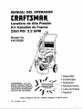
MANUAL
DEL OPERADOR
CRAFI"SMAN
®
Lavadora de Alta Presi6n
6.0 Cabal!os de Fuerza
2350 PSI 2.2 GPM
Modelo No.
919.762350
ADVERTENCIA:
Leer
•
•
•
•
•
este
manual y observar todas las
Precauciones
de Seguridad
e
Instrucciones
de Operaoi6n
antes de usar este equipo.
Seguridad
Ensamblaje
Operaci6n
Mantenimiento
Lista de Partes
, EspaSol
Sears,
16478
MGP-7023S0A
41t5/98
Roebuck
and
Co.,
Hoffman
Estates,
IL 60179
U.S.A.
TABLA
Garantia ....................................................
Pautas de Seguridad
Ensamblaje
Operaci6n
34
Servicio
y Regulaciones
35-37
Almacenaje
..........................................
37-39
Gu{a para Diagn6stico
............................................
39-43
Repuestos
43-45
C6mo
Mantenimiento
..........................
DE CONTENIDOS
....................................
GARANT|A
LIMITADA
ALTA PRESION
DE UN Ai_O PARA
......................
45-46
...............................................
de Problemas
...........................................
Ordenar
LAVADORAS
Repuestos
46
...... 47
48-51
......... Contratapa
CRAFTSMAN
DE
Por un afio a partir de la fecha de compra, y siempre que esta Lavadora Craftsman de Alta Presi6n se
mantenga y opere de acuerdo alas instrucciones en el Manual del Operador, Sears reparar_i cualquier
defecto de material o fabricaci6n sin costo alguno.
Siesta lavadora se usa para prop6sitos comerciales, la garantia s61o ser_t aplicable por 90 dias a partir
de la fecha de compra. Siesta lavadora se usa para alquiler, esta garantla s61o ser_iaplicable por 30 dias
a partir de la fecha de compra.
GARANT|A
LIMITADA
DE UN AI_IO DEL
MOTOR
CRAFTSMAN
Por un at_o a partir de la fecha de compra, y siempre que este motor Craftsman se mantenga y opere de
acuerdo alas instrucciones en el Manual del Operador, Sears reparar_ cualquier defecto de material o
fabricaci6n sin costo alguno.
Si el motor Craftsman se usa para prop6sitos comerciales o de alquiler, la garantia s61o sera aplicable
por 90 dias a partir de la fecha de compra. Esta garantia no cubre piezas sujetas a desgaste tales como
bujias y filtros de aire, los euales se gastan con el uso normal.
La garantia no cubre las reparaciones que se hagan necesarias debido al mal uso o negligencia de parte
del operador, incluyendo dafios causados por no suministrarle agua a la bomba o no mantenar el equipo
de acuerdo alas instrucciones contenidas en este manual.
SE PL_DE OBTENER SERVICIO POR GARANTIA SI SE LLEVA LA LAVADORA DE ALTA
PRESION AL CENTROiDEPARTAMENTO
DE SERVICIO DE GARANTiA MAS CERCANO EN
CUALQUIER LUGAR DE ESTADOS UNIDOS.
Esta garantia le otorga ciertos derechos
especificos y usted tambi_n podrla tenet otros derechos que varian de an estado a otto.
Sears,
Roebuck
and Co,, D/817
WA, Hoffman
34
IIIIIIIIIIIIIIII
Estates,
IL 60179
legales
PAUTAS
DE $EGURIDAD
- DEFINICIONES
Este manuel contiene inforrnaci6n que es importante que usted sepa y entienda. Esta informaci6n se relaciona con la
pmtecot6n de SU SEGURIDAD y la PREVENCI6N DE PROBLEMAS AL EQUIPO. Para ayudarle a identificar esta informecibn
usamos los siguientes elmbolos. Par favor leer este manual y prestar atenci6n especial a estes secciones. CONSERVAR
ESTAS DEFINICIONES/INSTRUCCIONE$.
A ADVERTENCIA
indica una situaci6n
potencialmente riesgosa, la cual, si no se evita
puede causar lesiones series o muerte,
_, PELIGRO indica una situacibn riesgosa
inminente que si no se evita ¢ausar_ lesiones
series o muerte.
INSTRUCCIONES
LA OPERACI_N
O EL MANTENINRENTO
A LA PROP|EDAD.
LEER Y ENTENDER
ANTES DE USAR ESTA UN|DAD.
RIESGO
RIEGO DE INCENDIO
EXPLOSION
_, CUIDADO indica una situaci6n potencialmente
peligrosa que si no se evita ouede causer
lesiones menores.
lOlall17
IMPORTANTES
INAPROPIADOS
DE ESTA UNIDAD PUEDEN CAUSAR LESIONES
TODAS LAS ADVERTENCIAS
DE SEGURIDAD E INSTRUCCIONES
QUEPUEDESUCEDER
O
DE SEGURIDAD
COMO
SERIAS Y DAI_OS
DE OPERACI(_N
PREVENIRLO
La gasoliney los vapores de gasolinapueden
encenderse
con las chispas de los
cigarrillos,amos el_ctrloos, gases de escape
y los componentes calientes de los motores
tales coma el mofle.
• Apagar el motor y permitir que se enfr{e
antes de agregar combustible el tanque.
El calor expandir_ el combustible en el
tanque lo cual puede causer un derrame y
posiblemente fuego o explosibn.
Tener culdado al Ilenar el tanque pare evitar
derramar el combustible. Retirar la lavadora
de presi6n
del _rea de relleno de
combustible antes de arrencar el motor.
• Mantener el nivel m,_xlmo del combustible
a 1,5 cm par debajo de la tape del tanque
de combustible
pare dejar sltio para la
expensibn.
Operar la unidad en un ambiente con
riesgos de exploel6n, puede causer un
incendio.
• Operar y agregar combustiblo el equipo en
_rees bien ventiladas
y libres de
obstrucciones. Equipar el_rea de operacibn
con exttnguidor(es) edecuado(s) pare
incendios de gasolina.
Los meteriales colocados contra la lavedora
de presi6n o cema de _sta pueden interfedr
con su ventilaci6n apropiada causando
sobreealentamiento y posible inflamaci6n
de los materieles.
• Nunca operar Ia lavadora de presi6n en un
_rea que contenga hierbas o tames secas.
El combustible indebidemente guardado
puede ceusar una ignici6n accidental. El
combustible indebidamente
asegurado
puede caer en las manos de nifios u otras
personas indebidas.
• Almacenar la gasotina en envase designedo
pare contener gasoline y en un lugar seguro
lejos del _lrea de trabajo.
• Inhaler los gases del escape
leeiones series o muerte.
causard
RIESGO A LA RESPIRACI6N
• Operar la lavadora de presi6n en un ,_rea
bien ventileda. Evitar &reas cerradas tales
coma garajes, s6tanos, etc.
• Nunca operar la unidad en lugares
ocupados par personas ni animeles.
• Algunos t_quidos limpiadores contienen
sustanciasque pueden causer dafio ata piel,
los ojos o los pulmones.
35
• Solo
user
Itquidos
limpiadores
especialmente
recomendedos
pare
lavadoras de alta presi6n.
Seguir las
recomendeclones del fabdcante.
INSTRUCCIONES
RIESGO
RIESGO POR OPERACION
INSEGURA
'.RI:IIt4'IttlII
RIESGO DE LESlONES
POR EL CHORRO
CHOQUE
ELliCTRICO
RIESGO DE
RIESGO DE INYEC¢ION DE
L|QUIDO
IMPORTANTES
QUE PUEDE
DE SEGURIDAD
COMO PREVENIRLO
SUCEDER
La operaci6n o mantenimiento inadecuados
de la lavadora de presibn puede causar
tesiones seriaso muerte al operador o a otras
personas.
Lapistola/tubo aplicadores unaherramienta
potente de Iimpieza y aun niSo podria
parecerle un juguete.
La fuerza reactive del chorro hard que el
splicador "patee" y pueda causar clue el
operador se resbale y caiga o dirija real el
chorro. La p_rdida de control del apticador
puede causar lesiones al mtsmooperador o
a otros.
Famllladzarse con la oparacibn y los controles
de la lavadora de presi6n.
Mantener a los nil'los alejados dela lavadora de
presi6n en toclo mornento.
Nunca burlar los disposltlvos de seguridad de
este equipo.
No operar la mdquinacon piezasfaltantes, rotas
o no autodzadas.
Nunce dejar desatendido el tubo aplicador
cuando la lavadora eat_ten operacibn.
Mantener el drea de trabajo Iibre de obstiiculos.
Pararse en una superficle estable y agarrar con
flrmeza la pistola/tubo aplicador. Prepararse
pars el retroceso de la pistols aplicadora cads
vez que se presione el gatillo.
• El chorro de los liquidos aalta velocidad
puede causar la mtura de algunos objetos
proyectando
sus psrtfculas
a altas
velocldades.
• Los objetos livianos o que no eat_n sujetos
se pueden
convertir
en proyectiles
peligrosos.
• Siempre usar anteojos de seguridad que
cumplan con la norms Z87 de ANSI. Siempre
usar ropa especial pars protegerse del chorro.
• Dirigir el chorro hacia tomacorrientes
o
interruptores el6ctricos, o hacia objetos
conectados al suministro eldctrico puede
causar choque eI6ctrico.
• Desconectar cualquier aparato el_ctrico antes
de intentar limpiarlo. No dirigir el chorro a
tomacorrientes ni a interruptores el6ctricos.
La m_iquina opera con fiuidos a atta presi6n
y a velocidades Io suficientemente altas pars
penetrar el cuerpo de personas y animales,
Io cual puede resultar en lesiones sedas y
amputacibn. Las p6rdidaa causadas por
conexiones flojas o gastadas pueden causer
inyeccibn y lesiones,
iNO TRATAR LA
INYECCI(_N DE LIQUIDOS COMO UN
SIMPLE CORTE! Obtener atencibn mi_dica
de Inmediato.
• Nunca cotocar las manos delante de la
boquilla.
• No dirigir el chorro hacia uno mismo ni hacia
otras personas.
• Asegurarse que la manguera y las conexiones
esten bienajustadas yen buenas condiciones.
Nunca agarrar la manguera ni las conexiones
durante la operactbn.
• No parmitIr que la manguera entre en contacto
con el mofle,
• Nunca poner ni quitar et tubo apficador ni los
acoples de la manguera mientras que el
sistema est_ presurtzado.
• Usar 0nicemente mangueras y accesorios de
alta presibn para servicio a 2000 PSI.
• Para aliviar la presibn del sistema, apagar et
motor, cortar el suministro de agua y tirar del
gati}lo hasta que el agua deje de flulr.
• Aliviar la presion del siatema antes de
tntentar
darle
mantenimiento
o
desensamblarlo.
RIESGO DE QUEMADURAS
QU|MICAS
(Cont.)
El uso de &cidos, quimicos t6xicos o
corroslvos,
venenos, insecticidas,
o
cualquler tipo de solvente lnflamable en esta
unidad pueden causar lesiones personales
serias o muerte.
• Nunca apuntar el tubo apticador ni dirigir el
choffo
a personas
ni artlmales,
•Para evitar que se accione accidentalmente
siempre enganchar el seguro del gatillo
cuando la pistola aplicadora no est6 en uso.
• Nunca fijar el gatillo permanentemente en la
posici6n de abierto.
• No user dcidos, gasoline, kerosene ni otros
materiales inflamables en esta unidad. $61o
usar detergentes dom6stlcos, limptadores y
desengrasantes recomendados para user en
esta lavadora de presi6n.
• Usar rope protectors pars evltar que los ojos
y la piel entrenen contacto con los materiales
rociados.
36
INSTRUCCIONES
RIESGO
RIESGO POR SUPERFICIES
CALIENTES
IMPORTANTES
DE SEGURIDAD
COMO PREVENIRLO
QUE PUEDE SUCEDER
• Durante la operaci6n,
s61o
superficies de control Mantener
alejados de la lavadora en todo
EIIos pueden no reconocer los
esta m_quina.
• El contacto con superficies caUentes,tales
como los componentes del escape, puede
causar quemadums serias.
S|mbolOSlnternacionales
[ L_._ _.......
de,-`]jl..__________.jit
Leerel Manual
. ..
Operad6n
iL_/Prende
(Cont.)
r (_
tocar las
a los nifios
momento.
fiesgos de
Detener_C_duetlble
IMPORTANTE:
El poderoso chorro producido por la lavadora de presi6n es capaz de dafiar superficies fr_giles tales como; madera,
viddo, pintura y molduras automotrices, y objetos delicados tales como floresy arbustos. Antes de rociar,inspeccionar
et objeto a limpiarse para asegurarse que es Io suficienternenterobustocomo para resistirla fuerza del chorrosin sostener
dafios. Evitar user chorros muy concentrados excepto para limpiarsuperficiesfuertes tales como concreto y acem.
Operar la unidad con el suministm de agua cerrado y sin flujo de ague le causar&dafios al equipo. Nunca se debe operar
esta lavadora de presi6n pot m&s de 2 minutos sin tirar del gatiUopara permitirel ingreso de ague _a ala bombay que
haga salirel agua caliente. Operar la lavadora de presi6n con el flujo de agua cortado anular&la garantfa.
Contenidos
O
de la Caja
•
•
•
Unidad pdncipaI de la lavadora a presi6n con ruedas
Asa
Manguera para alta presi6n
Manguera absorbente de soluciones
Unidad
qufmicas y filtro
a
• Pistola
• Tubo aplicador
pdncipat de la lavadora
presi6n con ruedas
Manguera para
alta presi6n
Asa
©
Manguera
Pistola y Tube aplicador
absorbente
de soluciones qufmicas y filtro
Bolsa contenlendo
• Casete de video
• ManualdelOperador
• Juego de timpiador de boquUlas y anillos "O" de
repuesto
• Botella de aceite para motor
• Tope amortiguador de caucho para pata y
elemento de fijaci6n
• Elementos de sujeci6n para el asa
Casete de video
L
Manual del Operador
_
Botetla de aceite
Elementos de sujeci6n
para el asa
<3_>
pare motor
0
An,los "O" de repuesto
37
Juego de limpiador de
boquillas
Tope arnortiguador de
caucho para pate y
elemento de fijaci6n
Herramlentas
Requeridas
part= el Ensamblaje
3÷
Llave regulable para tuercas
Ltave hexagonal Allen de 5mm 0ncluida)
Sacar
la Lavadora
de Presi6n
de la Caja
• Abrir la caja pot la parte de arn_a, bentro de la caja
ubicar y sacar Ia pistola y el tube aplicador, la cinta de
video y la botena de aceite.
• Cortar la caja a Io largo de la Iinea punteada.
• Sacar el empaque de la caja.
• Hacer rodar la unidad por la apertura de la caja.
O
Instalar el tope amortiguador de caucho en el bastidor
colocando el extremo roscado del pemo dentro de la
arandela. Luego, {:on la arandela en el perno, pasar
el extremo roscado del pemo por el tope amortiguador.
Colocar Ia parte roscada del tope amortiguador en el
mismo oriflcio donde estuvo montada la tabla de
madera en la lavadora a presi6n. A continuaei6n
colocar Iatuerca en forma de T sobre le parte roscada
del perno y, usando la Ilave Allen provista, sujetar el
tope amortiguador al bastidor.
NOTA: La manguera se encuentra en el rondo de la caja,
Preparaci6n
de la Lavadora
el Primer Uso
de Presi6n
III- Ill
pare
Nota: En la caja de la lavadora se incluye una cinta de
video que muestra como preparar la unidad pare su
operaci6n. Se recomienda vet esta cinta de video antes
de continuer con los siguientes pesos.
4. , Conectar el tubo aplicador ala pistola. Para ajustar,
girar la perilla en el sentido deI retoj. Ajustar a mano.
1. •tnsertar el asa en el bastidor.
• Ajustar las perillas gir&ndolas en el sentido de{ reloj.
• AJustar la perilla gir_ndola en el sentido del reloj.
5. • Cortar et amarre de la manguera para alta presiOn.
Desenrollar la manguera y conectar el extremo roscado
ala pistola.
(Ajustar la perilla en el sentido del
reloj pare enroscar en el pemo J)
_
(Inserter
perno J _q_i. E_ ex_remo
6. • Conectarlamangueraparaattapresi6nalasalidade
Ia presi6n en la lavadora y ajustarla firmemente a
mano. Conectar la manguera de succibn de quimicos
al niple en el conector de la manguera de Ia bomba.
roscaclo entra en el oriflcio superior)
2. • Quitar la plancha de madera del bastidor de la unidad.
Deseohar ta tuerca, el perno y tatabla. Quitar la tuema
del perno quejunta la plancha de madera al bastidor,
usando una tuerca ajustable.
MANGUERA
PARA
DE OU|MICOS
MANGUERA
PARA ALTA
PRESION
NOTA: Siempre mantener la manguera alejada del tubo
de escape del motor.
7. • Colocarlapistolaensambladaconeltuboaplicador
en el soporte de la lavadora a presi6n.
38
8.
, Cotocalacuerdadearranqueenelsoportetipo
argolla.
Pasar la cuerda por debajo del soporte a la
derecha de la argolla.
Elevar el mango de la cuerda de arranque y
deslizar la cuerda hacia la izquierda para que
entre en la argolla.
Luego deslizar el mango por atrds det soporte
hacia el lado izquierdo de la argolla.
El retroceso del motor halard el mango y Io
pondr_ en su posici6n final,
Familiarizarse
con la Lavadora
Lista de Comprobaci6n
Antes de continuar, por favor comprobar Io siguiente:
• Haber seguido las instrucolones
de ensamblaje
complefamante.
• Haber revisado dos veces quetodos los acoples est_n
firmemente ajustados.
IMPORTANTE: Antes de cualquier lntento de arrancar la
lavadora a presi0n, cemiorarse de inspeccionar el aceite
del motor (referirse a la secci6n Aceite del Motor en el
capftulo Operaci6n. Ver la pdglna 9).
de Presi6n
DE
A Y TUBO
APUCADOR
Leer el Manual del Operador y las Pautas de
Seguridad antes de operar la Lavadora de Alta
Presidn. Comparar esta ilustracibn con nuestra
lavadora de presi6n para famUtarizarse con los
diversos controles y dispositivos de regulacibn.
Conservar este manual para referencia futura.
MANGUERA DE
ALTA PRES_(_N
BOMBA: Desarrolla alta presibn.
TAPA DE
GASOUNA
REGULADOR DE PRESI(_N: Permite regular la presi6n
del chorro de salida.
INTERRUPTOR
PARA ARRANCAR Y APAGAR:
Coloca la unidad en la modalidad para arrancar con la
cuerda de arranque y paraApagar el motor cuando estd
funcionando.
CUERDA DEL ARRANCADOR:
el motor manualmente.
PARA
ARRANCAR
INTERRUPTOR
PARA
Y
TAPA
iDE ACEITEY
VARILLA
MEDIDORA
Se usa para arrancar
PISTOLA APUCADORA: Tiene un gatillo que permite
controlar el agua que se aplica a la superficie que se
desea lavar.
TAPA DE ACEITE Y VARILLA MEDIDORA:
donde se le reIIena aceite al motor.
MOFLE
Toma por
TAPA DEL TANQUE DE GASOUNA: La tapa se saca
para rellenar con gasolina sin plomo.
TUBO INYECTOR DE QU|MICOS Y FILTRO: Mezcla
el agua y el detergente en el punto de altmentacibn del
agua.
SALIDA DE ALTA PRESI6N:
Conexi6n para la
manguera de alta presi6n.
CHOKE: Palanquita de cebado para arrancar la unidad.
TUBO
INYECTOR DE
QUiMICOS Y
FILTRO
REGULADOR
PRESION
39
CONEXI(_N
DE
SAUDA DE
ALTA PRESI(_N
PARA
LA ENTRADA
AGUA
DE
A, Advertenola: Leer el Manual del operador. No
intentar operar este equipo hasta haber leido las
instrucciones
de Seguridad,
Operacibn y
Mantenimiento.
Hacer 1osiguiente para hacer que el motor funcione:
NOTk Labombade
Antes
de Arrancar
lalavadora
el Motor
a presi6nes unabombaseltada
y nuncadeberfanecesitarrellenoni cambioet aceite.
Nota: En la caja de la lavadora se incluye una cinta de
video que muestra como operar la lavadora de presi6n. Si
se dispone de una grabadora de video se recomienda ver
esta cinta antes de operar la unidad.
[
1
!
Aceite
del chorro mientras se estd rociando. Nunca colocar
Ias manos delante de la boquilla del chorro para
la forrna
chorro
porque
puede [
_, modificar
dvertencta:
Nunca de!
regular
la forrna
del abanico
lesionarse.
Apagado
de la Lavadora
de Presi6n
_, CUIDADO: Nooperarlabombaarnenosquelamanguera
I
de abastecimiento de agua est6 conectadaa una Ilave de
agua queest_ abierta, deIo contradode daSardla bornba.
I
•
Para apagar la lavadora de presibn, mover la palanca
de aceleraci6n a la posici6n de OFF/APAGAR.
•_, CUfDADO: Siempre verificar el nivel de aceite del
motor antes de cada arranque. Haoer que el motor
funcione sin aceite o con el nivel bajo puede
casusar dar3ossedos el motor.
del Motor
La unidad ha sido despachada sin aceite en el motor,
pero se inctuye una botella de aceite SAE 30 en la caja
de embalaje. Sacar la tapa de aceite con vadlla medidora
ubicada sobre el motor. La capacidad de aceite es
aproximadamente 591 ml (20 Onz.). La varilla medidora
estd claramente marcada con lineas indicadoras que
permiten saber cuando hay suficiente aceite.
No
sobrepasar la linea de Ilenado.
Rellenar el aceite
lentamente. Para revisar el aceite, introducir Ia vadlla
medidora dentro de la toma de aceite. Ajustar la medidora
y volverla a sacar. No sobrepasar la Iinea de Ilenado.
Rellenar el acelte lentamente.
ACELERADOR
NOTA: AI rellenaraceite al c_rter del motor, usar aceite de
alta calidad y grado SAE 30 conteniendo detergente
clasjficado para servicio SF, SG o SH. No usar aditivos
especiales. Seleccionar el grado de viscosidadde acuerdo
alas temperatura de operaci6n que se esperen tener.
•
La presi6n de agua del sistema no se ativiard con s61o
apagar el motor.
Despu_s que el motor se haya
detenido, presionar el gatillo de la pistola por unos 3
segundos para descargar la presi6n. La Iongitud del
chorro disminuird.
IMPORTANTE: Esta unidad est_ equipada con una vdlvula
t_rmica de alivio. Si se deja funcionar la unidad por varios
minutos sin presionar el gatillo de la pistola puede ser que
vadas gotas de agua salgan por esta valvula para enfriar
la unidad. El agua fluird del fondo de la bomba.
Mds fifo <i-----4°C/40°F---_>
Sint_tico
5W-30
I
mas caliente
SAE 30
A pesar que los aceites de vlscosidad m{31tiple (5W30,
10W30, etc.) mejoran e! arranque en climas frios, estos
pueden aumentar el consumo de acette cuando se usen
por encima de 4°C/40°F. Revisar el nivel del aceite con
mds frecuencia para evitar posibles daSos al motor por
operar con poco aceite. La capacidad de aceite del cdrter
es de 591ml (20 Onz.).
Gasolina
El motor de la lavadora de presi6n
enicamente gasolina sin plomo.
es de 4 tiempos.
Usar
A CUIDADO: No rellenar et tanque de gasolina demasiado.
S ernpre dejar espac o para a expans 6n de combust b e.
A. ADVERTENCIA: Nunca rellenar el tanque en interiores.
Nunca rellenar el tanque de combustible cuando el motor [
estd funcionando ni cuando estd caliente, No fumar ni
tener arnascercacuandosere
4O
enecornbustbe.
Usar gasolina regular sin plomo que est_ fresca y limpia
de m|nimo 85 octanos. No mezclar el aceite con la
gasolina. Si no se dispone de gasolina sin ptomo, se
puede usar gasoline con plomo.
IMPORTANTE: Durante el almacenaje, es importante
evitar la formacibn de sedimentos pegajososen el sistema
de combusti6n tales come en el carburador, manguera
del filtrode combustible o tanque, La experienciatambi_n
nos indlca que las gasolinas mezcladas con alcohol
(llamadas gasohol o que tienen etanol o metanol) pueden
atraer humedad que luego se separard y formard dcidos
durante el almacenaje de Ia unidad. La gasofina acfdica
puede daSar et motor mientras est_ almacenado. Para
evitarle problemas al motor, vaciar el sistema de
combustibn antes de almacenar la unidad pot 30 dfas o
m&s. Nunca echar productos limpiadores pare el motor
o el carburador en el tanque de combustible porque se
pueden causar daSos perrnanentes.
•
Apretar el gatillc de la pistola apl|cadora para descargar
la presi6n de aire acumulada al haber abierto la Ilave
del suministrode ague. La pistola disparar_ un pequei_o
chorm de agua. Esto facilitar_ el arranque del motor.
•
Enganchar el segum de la pistola aplicadora. Esto fijar_
el gatillc en posicibn y evitar& que se aplique un chorro
de alta presi6n en forma accidental.
SEGURO
•
El motor tiene una palanquita para CHOKE/RUN
(Cebado/Operacibn). Colocar la palanquita en la posicibn
de "Choke" (Cebado).
• El motor tiene otra palanquita pare control de aceleraci6n,
colocarla en la posici6n de la liebre. Siempre echar et
motor a funcionar con la palanquita en la posici6n de ta
liebre (o de alta velocidad).
NOTA: Nunca arrancar la lavadora a presi6n a menos
que est_ conectade a un suministro de agua y que la
Ilave est_ abierta.
Para Arrancar
la Lavadora
a Presi6n
• Sacar la tape del tanque de gasolina.
• Agregarlentamentagasolinasinplomoeneltanque.
• No sobrellenar.
CHOKE/
CEBADOR_..
Tomar la manija de le cuerda del arrancador y tirar de
ella lentamente hasta sentir una resistencia, luego tirar
de ella firmemente para que el motor arranque.
•
Conectar una manguera de jardfn ala boquilla de la
toma de agua en la lavadora a presi6n. Ajustarla
girando la boquilla de la toma de agua contra el sentido
del reloj.
NOTA: Si el motor no arranca de inmediato, apretar
el gatillo de la pistola para descargar la presi6n de
aire acumulada al haber abierto la Ilave del suministro
de agua. La pistola disparard un peque_o chorro de
agua. Esto facilitard el arranque del motor al tirar de
la cuerda. Si se necesita tirar de la cuerda del
arrancador m-'tsde cinco veces, regresar la palanca
de "CHOKE" (Cebado) a la posici6n RUN (Operaci6n).
Cuando el motor arranque, mover la paianquita del
"CHOKE" (Cebado) gradualmente ala posici6n de
"RUN" (Operaci6n).
Contectar la manguera de alta presi6n ala descarga
de Ia bomba.
Conectar la manguera de ague a Ia Ilave de suministro
de agua y abrirla.
Pare volver a arrancar el motor cuando est_ caliente,
cerciorarse que la palanquita de aceleraci6n eat_ en la
posici6n de la Uebre (alta velocidad) y que la palanquita
del "CHOKE" (Cebado) est_ en la posici6n de "RUN"
(OperaciSn).
_!
t t
Agarrar el mango de la cuerda del arrancador y tirar de
ella lentamente hasta sentir una resistencia, luego tirar
de ella firmemente.
41
Como
user la Lavadora
de Presi6n
Uso de Detergentes
En el extremo de Papistola aplioadora hay una boquilla
que ee puede deeltzar hacia adelante y hacia atr_s y que
tambi_n se puede girar a ambos lados. Con la boquilla
regulable se puede controlar la preslbn del chorro pare
alta o baja presibn. Tambidn se puede regular Ia forma del
chorro pare concentrado o abrirlo en forma de abanico.
•
IMPORTANTE: Usar detergentea y produetos qulmicos
que est_n diseSados especfficamente para usar en
lavadoras a presi6n. Pare aplicar detergente seguir estos
pasos: .,
•
•
Deslizar la boqutl/a hacia adelanta pare la presi6n ba_a
y hacia atrds para la presi6n alta.
Preparar el detergente o qufmico requeddo para la tarea.
Insertar el tubo succionador en el contenedor (no se
incluye el detergente).
pare
ALTA
PRESl6N
•
•
CHORRO CONCENTRADO
•
•
Para un lavado m_s efectivo, mantener la boqulfla de
roctado a una distancia de entre 20cm (8") y 60cm (24")
de la superficie que se est_ levando.
IMPORTANTE: Si se afloja la boquiUa concentrando el
chorro demasiado, especialmente en alta presibn,se puede
da5ar la superficie que se est& lavando,
•
•
La perilla de control de la presi6n est_ ubicada en la
bomba, Se puede aumentar la presi6n girando la perilla
en el s'entJdo del reloj o disminuirla girando la perilta
contra el sentido del reloj.
•
•
PERILLA
los
qutmicos
Jarro
__
NOTA: El primer paso es la preparaci6n de la soluci6n
adecuada de detergente o qufmtco apropiado para que
penetre en la suciedad y la suelte. Apltcar el detergente
o quimico a baja presi6n para evitar que salpique y se
desperdicie,
iDejar que Ia soluci6n repose sobre la
superficie unos 3 a 5 minutos pare que act_e.
NOTA: El segundo paso consiste en usar Ia lavadora a
presi6n para lavar la superficie que se ha preparado y
luego enjuagada.
BAJA
Pare regular la forma del chorro, girar la boquilla en el
sentido del reloj para abrir el chorro en forma de abanico
y contra el sentido del reloj para concentrar el chorro.
CHORRO EN ABANICO
_, ._
Manguera
los quimlcos
pare
PRESl6N
y Quimicos
DE
CONTROL
DE PRESI6N
Deslizar la boquilla regulable hacia adelante a la
modalidad de baja presi6n. No se puede aplicar
detergente/quimicos con la boquilla en la posici6n para
presi6n alta.
Revisar la posicl6n de la boquUla regulable.
Conectar una manguera de jardfn a la entrada de agua
(ver la secci6n "Arranque de la Lavadora a Presibn" en
la p_gina 9), verificar que la manguera pare alta presi6n
est,* conectada a la pistola aplicadora y a Ia bomba
(ver Ia secci6n "Ensamblaje") y arrancar el motor.
Aplicar el detergente/qufmico
a la superficie seca
comenzando de abajo y trabajando hacia arriba.
Permitir que el detergente/qufmico
repose de 3 a 5
minutos en la superficie antes de lavar y enjuagar.
Para lavar, comenzar por la parte inferior de la superficie
y avanzar hacia arriba apttoando en tramos largos
tra_apados y unfformes.
La lavadora a presi6n estd equipada con una perilla
pare regular la inyecci6n del qufmico. Con la perilla
totalmente abierta se obtendrd le mdximo de succi6 de
qulmico. Con la perilla totalmente cerrada no habr_
succi6n de qufmico. Glrar la perilla contra el sentido
del reloj pare lograr una mayor succ6n del detergente/
qufmico yen el sentido del reloj para una menor succ6n.
NOTA:Lapresl6n mdxima de la unidad viene reguladade f_brica.
No lntentar modiffcar esta reg'utaci6nhecha en f_brica.
PERILLA
REGULADORA
DEL
INYECTOR DE
DETERG/QU|M.
42
\
•
Se recomienda que despu_s de usar la lavadora de
presi6n se lave internamente la bomba, el inyector de
qufmicos y la manguera de qufmicos con agua limpia,
RESPONSABILIDADES
DEL
Paraelloslmplemente sumergirla manguera de qufmicos
en agua y sifonear agua por 1 a 2 minutos.
PROPIETARIO
Antes de
Cada Uso
TAREA DE MANTENIMIENTO
Cada 25
Horas
o Cada Afio
Cada 50
Horas
o Cada Afio
Cada 100
Horas
o Cada Afio
LAVADORA A PRESION
Inspeccionar/limpiar la malla de entrada.
X
Inspeccionar la manguera para elta presi6n,
X
Inspeccionar la manguera de succi6n de
detergente/qufmico y filtro.
X
Inspeccionar para detectar fugas por la pistola/tubo aplicador.
X
Purgar el aire y los contaminantes de la bomba
X
MOTOR
X
Inspeccionar el nivel de acelte.
X
Cambiar el acelte del motor.
Limpiar el filtro de aire,
Limpiar/reemplazar
ta bujia.
Recomendaciones
Especificaciones
Especificaciones
del Equipo
de la Lavadora
Eepecificaciones
La garantfa de la lavadora a elta presi6n no cubre las piezas que
han sido sujetas a mel uso o negligencia por parte del operador.
Para mantener lavalidez de la garantia, el operador deber_ hacede
el mantenimiento a la lavadora de alta preel6n como se indica en
este manual,
de Pres|6n
indice de Flujo
Presi6n
Unidades de Llmpieza (PSI x GPM)
2,2 GPM
2350
5170
Algunas regulaciones
peri6dicas ser&n necesarias para el
mantenimiento de la lavadora a elta presi6n.
I
Todas las r_,-:_gulaciones
en la Secci6n de Mantenlmiento de este
manual deber'&n Ilevarse a cabo por Io menos una vez por
temporada,
del Motor
RPM
Potencia
Luz de ]a Bujia
Capacidad de Gasolina
Acelte (Capacidad 591 ml / 20 Onz.)
Generales
3600
Una vez el afio se deber&n limpiar o reemplazar la bujla y el filtro
de aire y se deber_n inspeccionar la pistola y el tubo aplicador
para detectar puntos de desgaste, Una bujia y un filtro de aire
!impios asegurar_n una buena mezcla de aire y combustible y
ayudar_n a que el motor opere mejor y dure m_.s,
6,0 HP
0,76mm (0,030")
1.3 Lt, (1.5 Qts)
La bomba de lavadora a presibn es una bomba sellada y nunca
deberia neceeltar relleno ni cambio del aceite.
SAE 30
NOTA: Con el transcurso del tiempo, los anillos "O" de la pistola
rociadora se gastar_n, Con la unidad se provee un juego de
anillos "O" de repuesto que viene adherido al manual del
operador.
43
Mantenimlento
de la Lavadora
de Presi6n
Mantenimiento
Revisar
Inspeccionar y Camblar la Malla de Entrada: Examinar
la malla en el acople de entrada de la bomba. Umpiar si
estuviese atorada, reemplazar si estuviese rota.
•
Inspeccionar la Manguera de Alta PresiOn: La manguera
de alta preston puede deSarTollarfugas debido al desgaste,
estrangulamiento o maltrato. Inspeccionar la manguera
antes de cada uso para detectar cortes, fugas, abrasiones,
protuberancias en el form, dafios o juego de los acoples.
Si existiese alguna de estas condiciones, reemplazar la
manguera de inmediato.
del Motor
el Nivel del Aceite
El nivel del aceite deberd inspeccionarse antes de cada
uso de la lavadora o por Io menos cada 5 horas de
operaCi0n. Referirse a ta seccibn "Aceite del Motor" en
fa pdgina 9.
Cambio
de Aceite
del Motor
Cambiar el aceite cuando el motor todav{a estd caltente.
De preferencia, drenar el aceite por la parte superior
del motor como se muestra mds adelante. Drenar el
aceite con el filtro de aire hacia arriba. El acelte puede
drenarse por el lado inferior si fuese necesario.
Inspeocionar la Manguera de Suministro de Quimico/
Detergents y el Filtro: Exarninarla manguera de quirnico/
detergents y limpiarla si estuviese obstruida. La manguera
debe quedar bien _justada en et acopte de la bomba,
Inspeccionar para detectar fugas o roturas. Reemplazar el
fHtro o la manguera si alguno de ellos estuviese dafiado.
IMPORTANTE: Antes de inclinar el motor o el equipo para
drenar el aceite, drenar el combustible del tanque operando
el motor hasta que el tanque de combustible quede vacio.
FILTRO DE AIRE
Inspeccionar la Pistola/Tubo Aplicador: Examinar las
conexiones de Ia manguera a la pistola para cerciorarse
que est_n blen asegurados. Probar el gatillo presiondndoto
para asegurarse que regress a su posiciOn cuando se
suelte.
Purgar el Aire y los Contaminantes
de la Bomba
•
Seguir estos pasos para eliminar ef aire de la bomba:
• Preparar la lavadora de presibn como se describe en
ta SectiOn de Ensambla}e y conectar e_suministro de
agua.
• Retirar la extensi6n del tubo aplicador de la pistola
aplicadora.
• Tirar del gatillo en la pistola y rnantenerlo presionado.
Para drenar el aceite por Ia parte inferiordel motor, retirar
eltapOn de drenaje como se ilustraa continuacibn. Dejar
que el aceite se drene y volver a co{ocar el tapOn del
drenaje. Retirar la tapa con varilla medidora y rellenar
con aceite nuevo del grado recomendado. Arrancar el
motor y operarlo pot 30 segundos.
TAP_N
Seguir estos pasos para eliminar los contaminantes de la
bomba:
DE LLENADO
DADO DE 3/8"
• Preparar la lavadora de presiOncomo se describe en la
seccibn de ENSAMBLAJE, conectar el suministro de
agua. '
• Retirar la extension del tubo aplicador de la pistola
aplicadora.
• Arrancar el motor de acuerdo alas instrucciones en la
seccibn de OPERACION.
• Tirar del gatillo en la pistola y mantenedo preslonado.
• Soltar el gatillo y volver a instalar la extension del tubo
aplicador cuando el suministro de agua estd constante
y parejo.
TUBO
•
44
Apagar el motor. Esperar 30 segundos y volver a
inspeccionar el nivel de aceite. Si se requiere, agregar
aceite hasta que el nivel alcance la marca FULL (LLENO)
en la vadlla.
Mantenimiento del Filtro de AWe
No nmpiar el motor con un chorro de ague fuerte porque
el agua podria contaminar el sistema de combustible.
Despu_s de cadauso, con una brocha o cepillo limpiar
el protector con aberturas de ventilaci6n para evitar que
el motor se dafie por sobrecalentamlento.
El motor est& equipado con un elemento doble ovalado.
•Para
Iimpiar el elemento, aflojar los pernos y levantar la
cubierta.
Luego retirar el prefiltro y el cartucho
cuidadosamente.
•
•
LIMPIAR
Despu_s de limpiar el prefiltro, colocarlo en el cartucho.
Instalar el conjunto del filtro de aire en su base. Luego
instalar la cubierta sobre el filtro de aire y empernarlo
firmemente ala base.
LIMP_
•
PREFILTRO
Antes de operar et motor, limpiar el _rea del mofle para
eliminar et pasto y los residuos que puedan ser
combustibles.
_CARTUCHO
LIMPIAR
;
Filtro
BASE_
de Aire
de Doble
,
Limpiar
Elemento
y Reemplazar
la Buj|a
Reemplazar la buj{a cada 100 horas de operaci6n o una
vez cada afio, Io que sea primero. Esto ayudar_ a que el
motor arranque con facilidad y opere mejor.
Para limpiar el preflltro, lavarlo con detergente Ifquido y
con agua. Dejar que se seque bien antes de usar. No
aceitar el prefiltro. Reemplazarlo si estuviese muy sucio o
dafiado.
.030" (0.76 MM)
CAMBRADOR
NOTA: No user sotventes derivados de petr61eo, tales
como kerosene, porque deteriorarbn el cartucho del _tro.
No usar aire presurizado para limpiar el filtro. El aire
presudzado puede dafter el cartucho del filtro.
/Mantener
limpias las piezas y el motorl
RESISTENCIA
Carburador
El carburador de la lavadora de alta presi6n est& regulado
de f_bfica. El carburador no deber_ alterarse. Si la lavadora
de presi6n se usa a una altitud superior a 1,500 metros
(5,000'), consultar con el Centro de Servicio de Sears mbs
cercano para obtener las regulaciones necesarias para la
altitud.
_,
A
carga pesada el motor, y ouando el motor no provee la
,il CUIDADO:
Las bajas
del motor
imponen
una
potencia necesaria,
la velocidades
vide _til del motor
podda
ecortarse.
Limpieza
de la Boquilla
Si la boquilla se obstruyese con materiales extrafios, tales
como suciedad, la unidad podrfa desarrollar un exceso de
presi6n. Si la boquina se obstruyese parcialmente o se
restringiese, la presi6n de la bomba pulsarb. En estos
casos limpiar inmediatamente la boquilla usando el juego
limpiador suministrado con la unidad y siguiendo los pasos
indicados a continuacibn:
CUIDADO: La velocidad del motor se fij6 en la f_brica a
un punto apropiado y no debe requerir regulaciones
adicionales. No intentar alterar la velocidad del motor. En
caso que se sospeche que el motor est_ operando muy
lento o muy r_pido, Uevar ta lavadora de presi6n a un
Centro de Serviclo Autorizado de Sears pare que lo
reparen o regulen.
Tubo Aplicador
Regulable
1. Apagar la lavadora a presi6n y cerrar el suministro de
agua.
ADVERTENCIA: Las velocidades elevadas de operacibn
son peligrosas y aumentan el riesgo de daSos personales
o al equipo.
2. Desconectar el cable de la bujia.
45
3. Apretar el gatillo de la pistola aplicadora para aliviar
toda la presi6n de agua acumulada.
8.
Volvera instalar la boquilla en el tubo aplicador. Ajustar
firmemente para evitar fugas.
9. Volver a instalar el tubo aplicador en la pistola y abrir
el suministro de agua.
10. Arrancar la lavadora a presibn y probar haci_ndola
funcionar en presi6n alta.
4. Desconectar el tubo aplicador de la pistola.
5. Sacar la boquilla del extremo del tubo aplicador con la
llave Allen de 2ram provista con la unidad.
6. Umptar la boquilla usando el limpiador de boquUlas que
se provee o con un clip para papeles enderezado.
Introducir en un extremo de la boquilla y moverlo hacia
adelante hacia atr&s hasta eliminar la obstruccl6n.
7. Eliminar los residuos pasando agua al reverso por el •
tubo durante unos 30 segundos.
Esta lavadora de presi6n debe almacenarse de tel forma
que este protegida de la congelaci6n. No almacenar la
unidad en el exterior ni en un _rea donde la temperatura
caiga por debajo de O°C (32°F). Esto puede causar dafios
extensos a la unidad.
IMPORTANTE: Durante el almacenaje, es importante evitar
la formaclbn de sedimentos pegajosos en el sistema de
combusti6n tales como en el carburador, manguera del
filtro de combustible o tanque. La experiencia tambi_n
nos indica que las gasolinas mezcladas con alcohol
(llamadas gasohol o que tienen etanol o metanol) pueden
atraer humedad que Iuego se separar_ y forrnar_ _cidos
durante el almacenaje de la unidad. La gasolina acidica
puede dafiar el motor mientras est_ almacenado. Para
evitade problemas al motor,vaciar el sistema de combustibn
antes de almacenar la unidad por 30 dfas o m_s. Nunca
echar productos limpiadores para el motor o el carburador
en el tanque de combustible porque se pueden causar
dafios permanentes.
Si Ia unidad tlene que almacenarse
en lugares de
temperaturas congelantes, se deber_ usar un anticongelante
no tbxico R.V. para protegerla de ta congelaci6n.
Preparaci6n
de la unidad
su Almacenamiento
para
NOTA: Si no se tiene planeado usar la Iavadora de presi6n
por 30 dfas o mas, debe preparase la unidad para su
almacenamiento.
Preparaci6n
Preparaci6n
" Cerciorarse de poner el interruptor en la posici6n de
"OFF" (apagado) y que el cable de la bujia est_
desconectado.
•
Primero agregarle estabilizador de combustible al
tanque de gasolina.
•Hacer
funcionar la lavadora por 5 minutes completos
para permitir que el estabilizador de combustible entre
atodo el sistema de combusti6n.
• Apretar el gatillo de la pistola para aliviar la presibn de
la manguera de presi6n. Desconectar la manguera de
alta presibn y la manguera de jardfn de la unidad.
NOTA: Mientras se Ileve a cabo este procedimiento,
cerciorarse que la bomba tenga su suministro de agua y
que el agua salga de la unidad. NUNCA permitir que la
unidad funcione sin que corra agua por la bomba.
•
A continuaci6n,
apagar el motor y desconectar
sum!nistro de agua.
•
=
el
•
Desconectar el cable de la bujfa y sacar la bujfa.
•
Echar una cucharadita de aceite en el orificio de la buj{a.
•
Taponar el odflcio con un patio y tirar de la manija de la
cuerda del arrancador varias veces para lubricar la
cSmara de combusti6n.
•
de ia Bomba
del Motor
Volver a colocar la bujfa, pero no conectar el cable de la
buj{a.
46
Tirar de la manija del arrancador 4 a 6 veces para
descargar el agua remanente en la bomba.
Inclinar la unidad con el orificio de entrada de agua
apuntando hacia arriba.
•
Si se va a guardar la unidad en un lugar donde la
temperatura
caiga bajo 0°C (32°F), echar aproximadamente 1/4 de taza de anticongelante no t6xico
R.V. por el orificio donde se conecta la manguera de
agua a la bomba.
•
Poner la m_quina aI derecho y tirar de la manija del
arrancador de 4 a 6 veces para hacer circular el
anticongelante dentro de la bomba hasta que expulse
un poco.
S|NTOMA
CAUSA
SOLUCI6N
El motorno
1. La palanquita de aceleracibn del motor est_ en la
posici6n"OFF" (APAGADO).
2. La vdlvula de "Choke" (cebado) no esta en Ia
poelcibn de "Choke".
3. Acumulaci6n de presi6ndespu_s del uso iniciel.
1. Deslizarla pslanquitsde aceleraci6nala posici6nde la
"l-iebre".
2. Deelizarla palanquitaala posick_nde"Choke".
1. La boquilla de la pistola no est_len la poelcibn de
absorber.
2. Lamella de succibnde qufmicosest_ obstruida.
1. Colocar Is boquiUa en la posici6npare baja presi6n.
_'q'_ca
No absorbe
quimk?,o
3. La succi6n de quimicos no est_ trabajando.
4. El orificio del inyector de quimicos est& obstruido.
5. Inyector de detergente/quimicos cerrado.
La bomba
funciona
normelmente
pero la preel6n
no alcanza los
niveles
espeelficados.
2. Boquillaen la poelci6n de baja presi6n.
3. Boquilla incorrecta o gastada.
4. La bomba absorbe aire.
1. La bombs absorbe aire.
2. La mafia de la entrada de la manguera del jardln
est& obstruida.
3. Sellos o empaques gastados.
4. Suministro de agua inadecuado.
5. Valvulas de entrada o descarga sucias o gastadas.
6. Fugas en la manguera de descarga.
Lapreel6n cae
despu6s de un
)enodo normal
de uso
Bomba ruidosa
1. Boquilla atorada, o parcialmente obstruida.
2. Boquillagastada.
3. V_lvulas de la bomba estSn gastadas, sucias o
pegadas.
4. Empsque del pistbn de ta bomba est8 gastado.
1. Verificar que las mangueras y scoples no tengan fugas de
aire. Purger el aire de la manguera de jardin.
2. Limpiar. Inspeccionar el fiRrocon frecuencia.
3. Inspeccionar y reemplazar.
4. Inspecelonar lamanguera pars ver que no este setrangulada
o acodsda
5. Verificarqueel flujode suministro ala bomba sea eladecuado.
Asegurarse que latemperature no exceda (63°C/145°F).
6. Limpiar tasvSIvulas de entrada y descarga. Reemplazar si
fuese necesario.
1. Usar el juego para limpieza de boquillas pare eliminar la
obstrucci6n. (Referirse ala secci6n Mantenimiento de
Boquillas en el capftulo Servicio y Regulaciones)
2. Limpiar o reemplazar.
3. Reviser y reemplazar.
4. Reviser y reemplazar.
1. Reducir latemperature por debajo de 63°C 6145°E
2. Verificar que las mangueras y acoples no tengan fugas de
elre.
3. Reviser, limpiar o reemplazar.
4. Reviser y reemplazar si fuese necesario.
!. Ague muy catiente.
2. Bomba absorbe aire.
3. V&lvulas sucias o gastadas.
4. Rodamientos gastados.
Presenciade
1. ARehumedad.
Ague en et Aceite 2. Empaque del pist6ny sellosde aceResgastados.
_Re iechoso)
Agua Goteando
de la Bomba
2. Inspeccionar la malla de quimicos, limpiar si estuviese
obstruida.
3. Cerciorarseque elextremo del tubo de succi6nde quir'nicos
est_ sumergido.
4. Inspeccionar y timpiar.
5. Abrir el inyectorde quimicos girandola pedllade mgulacibn.
1. Verificarel suministrodeagua y la malla del fil_opera detecter
cualquier bloqueo. Inspeccionar lasmanguefas para detecter
si hay bloqueos, estrangulaciones, fugas, etc.
2. Hatar el extremo de la boquilla hacia atr_s ala posici6n de
presi6n elta.
3. Revisar y reemplazar.
4. Cerciorarse que las mangueras y acoples no tengan fugas
de aire.
5. Limpiar la boqulUa.
1. Suministro de agua restringido.
5. Boquilla obstruida.
Presi6n
Ructuante
3. Preelonarel gatillode la pL_tola.
1. V,_lvulat6rmicade aliviofuncionando normelmente
2. Acoples ttojos.
3. Anillos "O" de lagufadel pi_ o retenes gastados.
4. Empaque del pist6n gastado.
Goteo de AeeRe 1. Sello de ace'Regastado.
2. Tap6n de drenaje flojo o anitlo "O" del tsp6n
gastado.
47
1. Cambiar el aceRe.
2. Revisary reemplazar lossellosde aceRe.
1. Est_ protegiendola bomba si la lavadora est8 funcionando
por un tiempo largo perosin usarse, Apagar el motor.
2. Ajustar.
3. Reviser y reemplazar.
4. Reviser y reemplazar.
1. Revisery reemplazar.
2. Ajustar el tap6n de drenaje o reemplazar el aniflo "O".
No sobreajustar.
CRAFTSMAN
2350 PSI MAQUINA
LAVADORA DE ALTA PRESION 919.762350
3
16
19
7
5
8
14
VEA LA PAGINA
VERSION
16
EN INGLES
48
CRAFTSMAN
2350 PSI MAQUINA LAVADORA DE ALTA PRESION 919.762350
0_52
49
BOMBA PARTES # PK16482
CRAFTSMAN
2350 PSI MAQUINA LAVADORA DE ALTA PRESION 91 g,762350
BOMBA PARTES # PK16482
PARA LISTE DE PARTES
VEA LA PAGINA 18
VERSION
EN INGLES
50
CRAFTSMAN
2350 PSi MAQUINA LAVADORA DE ALTA PRESION 919.762350
MOTOR PARTES # 121602-0206-E1
PARA LISTE DE
VEA LA PAGINA 19-27
VERSION
EN INGLES
51
52
53
Para solicitar servicio de reparaci6n
o
repuestos que usted necesite, Ilamar
de 7 am a 7 pm, los 7 dias de ia semana al
1 -800-366-PART
(1-800-366-7278)
Para serv|oio de reparaci6n en su domic|lio
de electrodom6stioos
de las princlpales
marcas, Hamar las 24 horas de! dia,
los 7 dlas de la semana al
1 -800-4-REPAIR
(1-800-473-7247)
Para la ubicaei6n del Centro de
Repuestos y Reparaei6n de Sears
en su _rea, Ilamar las 24 horas
del dias, los 7 Was de la semana al
1-800-488-1222
Para informaci6n sobre |a compra de un
Contrato de Mantenimiento de Sears
o para averiguar sobre alg,',n Contrato
existente, ilamar de 9 am a 5 pm,
de Lunes a S_;bado al
SF.ARS
1-800-827-6655
SEARS
Arnenca_s Repair Spe_a[tsts
Sears,
Roebuok
and
Co.,
Hoffman
Estates,
IL 60179
U.S.A.