1
PRO.FORM
Model No. 831.299450
Serial No.
Find the serial number in the location
shown below. Write the serial number
in the space above for reference.
635C
USER'S MANUAL
Serial
SEARS, ROEBUCK AND CO.
HOFFMAN ESTATES, IL 60179
www.proform.com
new products,
prizes,
fitness tips, and much morel
P O'FORM
635CW
TABLE OF CONTENTS
IMPORTANT PRECAUT!CNS .................................................................
BEFORE YOU BEGIN .......................................................................
ASSEMBLY ...............................................................................
OPERATION AND ADJUSTMENT
.............................................................
HOW TO FOLD AND MOVE THE TREADMILL
..................................................
MAINTENANCE AND TROUSLE-SHQQT!NG
...................................................
CONDITIONING GUIDEL!NE-S ...............................................................
PART LIST ...............................................................................
ORDERING REPLACEMENT PARTS ..................................................
FULL 90-DAY WARRANTY. ..........................................................
Note: An EXPLODED DRAWING is attached in the center of this manual.
3
5
6
8
18
19
21
23
Back Cover
Back Cover
IMPORTANT
5,
j,
Do
PRECAUTIONS
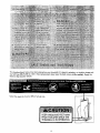
The decalsshownbelowhavebeenplacedon yourtreadmill.If a decalis missing,or illegible,pleasecall
our toil-free HELPLINE to order a free replacement
deoa[ in the location shown.
decal (see the back cover of this manual). Apply the
No[e: This dec_f is shown at 38% of actual size.
4
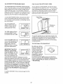
BEFORE YOU BEGIN
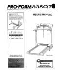
Thank you for selecting the revolutionary PREFORM"
635CW treadmill, The 635CW treadmill combines advanced technology with innovative design to help you
get the most from your exercise program in the convenience and pdvacy of your home. And when you're not
exercising, the unique 635CW can be folded up, requiring less than hail the floor space of other treadmills.
Monday through Saturday, 7 a.m, until 7 p.m. CentraJ
Time (excluding holidays). To help us assist you,
please note the product model number and serial number before calling. The model number of the treadmill
is 831.2994-50. The serial number can be found on a
decal attached to the treadmill (see the front cover of
this manual for the location).
For your benefit, read this manual carefully before
using the treadmill. If you have additional questions,
please c&ll our toll-free HELPLINE at 1-800-736-687g,
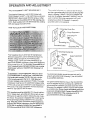
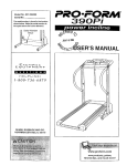
Before reading further, please re,_iew the drawing
below and familiarize yourself with the parts that are
labeled.
Book Holder-Water Bottle
Holder (Bottle
not included)
I
Console
Upper Body Arms
Lock Knob
LEFT SIDE
Key/Clip;
--
Walking
f Switch
.Circuit
Breaker
Foot Rail
Power Cord
Cushioned Walking Platform
' Roller
Adjustment Bolts
5
ASSEMBLY
........
y requires two people. Sat the treadmill in a cleared area and remove all packing materials, Do not
dispose of the packing materials until assembly is completed. Assembly requires the included allen wrenc_
and your own phillips screwdriver (_C3=====,- .
Note: The underside of the treadmill walking belt is coated with high-performance lubricant. During shipping, a
small amount of lubricant may be transferred to the top of the walking belt or the shipping carton. This is a normal
condition and does not affect treadmill pe_fformance. If there is lubricant on top of the walking belt, simply wipe off
the lubricant with a soft cloth and a mild, r_on-abrasive cleaner.
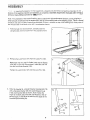
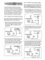
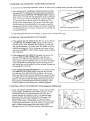
1. With the help of a second person, carefully raise the
Uprights (82) until the treadmill is in the position shown.
2. Remove the Lock Knob (!27) from the Lock Pin (132).
Make sure that the Lock Pin Collar (130) and the Spring
(129) are on the Lock Pin as shown. Insert the Lock Pin
into the Lock Knob Bracket (128).
127
Tighten the Lock Knob (127) onto the Lock Pin (132).
128
3. Refer to drawing 3a. Loosely thread a Handrail Bolt (78)
with a Handrail Washer (36) into each Extension Leg
(103) and Handrail (85) as shown. Note: Notice the
angle of the Bolt; attach the Bolt and Washer at the observed angle. It should be the same as the angle of the
Handrail (see drawing'3b).
85
o l
103
C-78
6
I
4. SIide the upper end of a Handrail (85) and then the
Extension Leg (34) into the right Upright (82) as shown.
(Note: It may be helpful to tip the Uprights [11 ] forward
as you insert the Extension Leg.)
4
85
Slide the other Handrail (85) into the left Upright (82) as
described above.
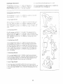
5. With the help of a second person, carefully tip the
Uprights (82) down as shown. Make sure that the
Extension Legs (103) and Handrails (85) remain in the
Uprights,
A_ach each Extension Leg (103) with two Short Screws
(101) as shown. You may need to press down on the
top of the Uprights (82) to fully insert the Extension
Legs. Tighten the Handrail Bolts (75).
85
Note: One replacement Base Pad (97) may be included.
Use the extra Base Pad if one becomes worn or needs
to be replaced.
97
With the help of a second person, carefully tip the
Uprights (82) back to the upright position.
6. Refer to drawing 6a. Locate the left Rear Foot (59) on
the treadmill. If the left Rear Foot touches the floor, go to
step 7. If there is a space between the left Rear Foot and
the floor, follow the instructions below.
Hold the treadmill firmly with both hands, and raise the
treadmill to the storage position as described on page 19.
Refer to drawing 6b. Using a phillips screwdriver, remove
the Screw (60), the right Rear Foot (59), and the Rear
Foot Spacer (136) from the treadmill. Reattach the right
Rear Foot without the Rear Foot Spacer. Hold the treadmill with both hands, and lower the treadmill as
described on page 19.
Check the left Rear Foot (59 [see drawing 5a]). If the left
Rear Foot is still off the floor, raise the treadmill and remove the left Rear Foet. Snap the Rear Foot Spacer
(136) onto the left Rear Foot and reattach the left Rear
Foot. Carefully lower the treadmill.
59
6b
60
59
136
7. Make sure that all parts are tightened before you use the treadmill. Keep the included allen wrench in a
secure place. The allen wrench is used to adjust the walking belt (see page 20). To protect the floor or carpet
from damage, place a mat under the treadmill.
7
OPERATION
THE PERFORMANT
AND ADJUSTMENT
LUBE TM WALKING
BELT
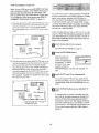
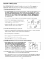
This [:roduct is for use cr_ _ nomir'a1120-volt circuit,
and t_as a grounding plug that looks like tile plug illustrated in drawing 1 below. A temporary adapter that
looks like the adapter illustrated in drawing 2 may be
used to connect the surge suppressor to a 2-pole
receptacle as shown in drawing 2 if a property
srounded outlet is not available.
Your treadmill features a walking belt coated with
PERFORMANT LUBE TM, a high-performance lubricant.
IMPORTANT: Never apply silicone spray or other
substances
to the walking belt or the walking platform. Such substances will deteriorate the walking
belt and cause excessive wear.
1
HOW TO PLUG IN THE POWER CORD
_Grounded
[_ _..j
II
_
Outlet Box
_
r_l
Surge Suppressor
;',J;_J
Grounding Pin
unded Outlet
Grounding Plug"_
2
t_Grounded
II /rl _/ I
II _
_
Your treadmill, like any other type of sophisticated
electronic equipment, can be seriously damaged by
sudden voltage changes in your home's power.
Voltage surges, spikes, and noise interference can
result from weather conditions or from other appliances
being tumed on or off. To decrease the possibility of
your treadmill being damaged, always use a surge
suppressor
with your treadmill (see drawing 1 at
the right).
Outlet Box
Adapter
-
Surge buppressor
Metal Screw
To purchase a surge suppressor, see your local
PROFORM dealer or call toll-free 1-800-366-7278
The temporary adapter should be used only until a
properly grounded outlet (drawing 1) can be installed
by a qualified electrician.
and order part number 146148. Use only a singleoutlet surge suppressor that is UL 1449 listed as a
transient voltage surge suppressor (TVSS). The surge
suppressor must have a UL suppressed voltage rating
of 400 volts or less and a minimum surge dissipation of
450 joules. The surge suppressor must be electrically
rated for 120 volts AC and 15 amps.
The green-colored rigid ear, lug, or the like extending
from the adapter must be connected to a permanent
ground such as a properly grounded outlet box cover.
Whenever the adapter is used it must be held in place
by a metal screw. Some 2-pole receptacle outlet box
covers are not grounded, Contact a qualified electrician to determine if the outlet box cover is
This product must be gro'unded. If it should malfunction or break down, grounding provides a path of least
resistance for electric current to reduce the risk of elec-
grounded
tric shock. This product is equipped with a cord having
an equipment-grounding
conductor and a grounding
plug. Plug the power cord into a surge suppressor,
and plug the surge suppressor into an appropriate
outlet that is properly installed and grounded in
accordance
with all local codes and ordinances,
8
before using
an adapter.
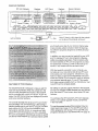
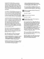
CONSOLE DIAGRAM
IFIT.com Indicator
Speed V Button
/
ncline Display
Displays
---'
LED Track
Displays
,,,,,
Clip
,,:_o ,,,,,,,,,,,r,_
Key
Manual Indicator
!
Note: If there is a thin sheet of clear plastic
on the face of the console, remove it.
you through every step of your workout. High-energy
music provides added motivation. Each CD features
two different programs designed by certified personal
trainers,
In addition, you can connect the treadmill to your VCR
and TV and play iFiT.com video programs (videocassettes are available separately). Video programs offer
the same benefits as iFtT.cem CD programs, but add
the excitement of working out with a class and an instructor-the
hottest new trend at health clubs.
FEATURES OF THE CONSOLE
The treadmill console is designed to help you get the
most from your exercise. When the console is in the
manual mode, the speed and incline of the treadmill
can be controlled with a touch of a button. As you exercise, the LED track and the four displays will provide
continuous exercise feedback.
The console also features advanced iFIT.com interactive technology. IFIT.com technology is like having a
personal trainer right in your home. Using the included
audio cable, you can connect the treadmill to your
home stereo, portable stereo, or computer and play
special iFIT.com CD programs (one CD is included).
IFIT.com CD programs automatically control the speed
and incline of the treadmill as a personal trainer guides
With the treadmill connected to your computer, you
can also go to our new internet site at www.iFIT.com
and access even more programs. Choose from a selection of basic programs that interactively control the
speed and incline of your treadmill to help you achieve
your personal exercise goals. Or use iFIT.com audio
and video programs directly from our interact site. Visit
www.iFIT.eom for complete details.
By adding an optional upgrade module to the treadmill,
you can use virtually endless features from our internet
site. See www.iFIT.com to learn about other iFIT.com
features.
To purchase other iFIT.corq CD's, iFIT.com videocas÷
settes, or an optional upgrade module, call toll-free
1-800-735-0768.
To use the manual mode of the console, follow the
steps beginning on page 10. To use iFIT.com CD or
video programs, refer to page 14. To use iFIT.com
programs directly from our internet site, see page 16.
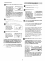
GETTING-STARTED
Attachthe clip to the waistband
of your clothing.
B
Standonthefootrails
ofthe treadmill,Find
the clipattachedtothe
key,andslidetheclip
ontothewaistband
of
yourclothing.Next,in-
See GE-FI"ING STARTED on this page.
B
mode will automatically
be selected, as shown
by the MANUAL CONTROL indicator. If the
iFIT.com indicator is lit, press the PROGRAM button to select the manual mode.
Plug in the power cord.
[_J Press the START button or the SPEED A button
to start the-walking belt.
See HO_W TO PLUG IN THE POWER CORD on
page 8.
[]Move
A moment after the button is pressed, the walking
belt will begin to move at 1 mph. Hold the handrails and carefully begin walking.
the ordoff switch to the on position,
Locate the on/off
switch on the treadmill near the power
cord. Move the switch
OnJ
Position
to the on position.
[]
Select the manual mode.
When the key is inserted, the manual
serf the key fully into the console. Test the clip by
carefully taking a few steps backward until the
key is pulled from the console. If the key is not
pulled from the console, adjust the position of
the clip as needed. Then, remove the key from
the console.
B
Insert the key fully into the console.
Insert the key fully into the console.
When the key is inserted, the four displays and various indicators on the console
will light.
As you exercise, change the speed of the walking
belt as desired by pressing the SPEED z_ and
buttons. To change the speed setting quickly, press
the QUICK SPEED buttons. Note: After the buttons are pressed, it will take a moment for the
walking belt to reach the selected speed setting.
To stop the walking belt, press the STOP button.
The TIME display will begin to flash. To restart the
walking belt, press the START button or the
SPEED z_ button,
Lq
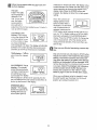
Change the incline of the treadmill as desired.
To use the manual mode of the console, follow the
steps beginning on this page. To use iFIT.com CD or
video programs, see page 14. To use iFIT.com programs directly from our intemet site, see page 16.
To change the incline of the treadmill, press the
incline buttons. Each time a button is pressed, the
incline will change by 0,5%. The buttons can be
held down to chan.ge the incline rapld¥
Ncte: The console can display speed and distance in
either miles or kilometers (see SPEED/MIN-MILE DISPbXY on page 11 ). For simplicity, all instructions in this
' manual refer to miles.
Note: In the incline display, the
first indicator will
light when the
incline is set at
1.5%. The second indicator will
Incline Display
I
POW£R
It,Kt LI_
light when the
incline is set at 2% or 2.5%, the third indicator will
light when the incline is set at 3% or 3.5%, and so
forth. After the incline buttons are pressed, it will
take a moment for the treadmill to reach the selected incline setting,
10
[]Follow
your progress
the four displays.
measured in minutes per mile). The display will alternate between one number and the other every
seven seconds, as shown by the arrows in the
display. Note: When the SPEED buttons are
with the LED track and
The LED
Track--The LED
track represents a
distance of 1/4.
pressed, the display will show the current speed
setting.
mile. As you exercise, the indicators around the
track will light in
sequence until you have wa!ked or run 1/4 mile. A
new lap will then begin.
display--This
display
shows the distance that
DISTANCEILAPS
you
have walked or run
and the number of laps
yOU have completed
, \
Note: The console can
display speed and distance in either miles or
kilometers. To see which
unit of measurement is
I
N
1.5 I.J
When you are finished
I[=1 key.
CALS
122
FAT CALS,
SPEED/MIN-MILE
!_
SPEED
exercising, remove the
When you are finished using the treadmill, move
the on/off switch near the power cord to the off
position and unplug the power cord.
iNG on page 21). Every seven seconds, the display will change from one number to the other, as
shown by the arrows in the display.
display--This
display
shows the speed of the
walking belt and your
current pace (pace is
(kin)
Step onto the foot rails and press the STOP button.
Adjust the incline of the treadmill to the lowest
setting. The incline must be at the lowest setting when the treadmill is folded to the storage
position or the treadmill will be damaged; Next,
remove the key from the console and put it in a secure place. Note; If the displays and indicators
on the console remain lit after the key is removed, the console is in the "demo" mode.
Refer to page 17 and turn off the demo mode.
TIME
CALORIES
/ MILE
display. Press the SPEED z&button to change the
unit of measurement. When the desired unit of
measurement is selected, remove and then reinsert the key,
[ Arrow
1_..
!
DISTANCE LAPS
TIME display--Thi_"display shows the e!apsed
time.
display--This
display
shows the approximate
numbers of calories and
fat calories you have
burned (see FAT BURN-
MIN
selected, hold down the
STOP button while inseding the key into the console. An "E" for English miles or an "M" for metric
kilometers will appear in the SPEED/MIN-MILE
(one ap equals 1/4 mile). The display ,,vill alternate
between one number and the other every seven
seconds, as shown by the arrows in the display.
CALORIES/FAT
I E1r
SPEED
ft.31
MIN I MILE (kin)
11
::HOW
::
•
t
HOW TO CONNECT Y()UR PORTABLE STEREO
::::,
•
:
•
.
i
_
:._4
;_i
X
:;>2
To use iFIT.eom CD's, the treadmilt must be connected to your portable CO player, portable stereo,
home stereo, or computer with CD player. See pages
12 and 13 for connecting instructions. To use iFIT.com
videocassettes,
the treadmill must be connected to
your VCR. See page 14 for connecting instructions. To
use iFIT.com programs directIy from our internet
site, the treadmill must be connected to your home
computer. See page 13 for ccnnecting instructions.
Note: If your stereo has ate"RCA-type AUDIO OUT
jack, see instruction A below. If your stereo has a
3.Smm LINE OUT jack, see instruction B. If your
stereo has only a PHONES jack, see Instruction C.
A. PIug one end of the audio cable into the jack on the
front of the treadmill near the power cord. Plug the
other end of the cable into the included adapter. Plug
the adapter into an AUDIO OUT jack on your stereo.
HOW TO CONNECT YOUR PORTABLE CD PLAYER
Note: If your CD player has separate LINE OUT and
PHONES jacks, see instruction A below. If your CD
player has only one jack, see instruction
B.
A. Plug one end of the audio cable into the jack on the
P6ht_of the treadmill near the power cord. Plug the
other end of the cab,_ into the LINE OUT jack on
your CD player. Plug your headphones into the
PHONES jack.
i
i
Audio
+-@_
+
uable
Adapter
B. Plug one end of the audio cable into the jack on the
front of the treadmill near the power cord. Plug the
other end of the cable into the LINE OUT jack on
your stereo.
A
B
i _'f'_3i
Audio
_]
Head-
i_-.--_ i
Cable
_
phones
IF
+
i[_
_6")i
Audio
+¢ [_]
B. Plug one end of the audio cable into the jack on the
front of the treadmill near the power cord. Plug the
ether end of the cable into a 3.Smm Y-adapter
(available at electronics stores). Plug the Y-adapter
into the PHONES jack on your CD player. Plug your
headphones into the other side of the Y-adapter.
Cable
_3
C. Plug one end of the audio cable into the jack on the
front of the treadmill near the power cord. Plug the
other end of the cable into a 3.5ram Y-adapter
(available at electronics stores). Plug the Y-adapter
into the PHONES jack on your stereo. Plug your
headphones into the other side of the Y-adapter.
C
L.
-................
i[_ ('_ i
Audio
+ @ _]
Cable
i
3.5mm
','-adapter..
_1
i P,0,s®i
,o.............
""]
Ir
[]
Headphones
@i
'
Audio
Cable
3.5ram
Y-ad_
Headphones
12
HOW TO CONNECT YOUR HOME STEREO
HOW TO CONNECT YOUR COMPUTER
Note: If your stereo has an unused LiNE OUT jack,
see instruction A below, If the LINE OUT jack is
being used, see instruction
B.
Note: If your coml buter has a 3.Smm LINE OUT jack,
see instruction A. If your computer has only a
PHONES jack, see instruction B.
A. Plug one end of the audio cable into the jack on the
front of the treadmill near the power cord. Plug the
other end of the cable into the included adapter.
Plug the adapter into the LINE OUT jack on your
stereo.
A. Plug one end of the audio cable into the jack on the
front of the treadmill near the power cord. Plug the
other end of the cable into the LINE OUT jack on
your computer,
A
i_
L ..........
_
.T* ..'
Aud,o
Adapter-
' "",L"."."_"
".T.:'_"
__
Cable
Audioj
B. Plug one end of the audio cable into the jack on the
front of the treadmill near the power cord. Plug the
other end of the cable into a 3.5ram Y-adapter
(available at electronics stores). Plug the Y-adapter
into the PHONES jack on your computer. Plug your
headphones or speakers into the other side of the
Y-adapter.
B. Plug one end of the audio cable into the jack on the
front of the treadmill near the power cord. Plug the
other end of the cable into the included adapter.
Plug the adapter into an RCA adapter (available at
electronics stores). Next, remove the wire that is
currently plugged into the LINE OUT jack on your
stereo and plug the wire into the unused side of the
B
h
RCA adapter. Plug the RCA adapter into the LINE
OUT jack on your stereo.
h
i@@i ud!o_=3.smm__
ae,e= Y-adapter
Headphones/Speakers
,f_.........."
i._
t .........
,-................
i _'_ @i
@_
RCA
Audio
i
*,
Cable
AdapteFAdapter
Wire removed from _c:_,,-,
LINE OUT jack
13
_
, :..........;_,,_:,
HOW TOaCONNECT YOUR VCR
Note: If your VCR has an unused AUDIO OUT jack,
see instruction
A below, if the AUDIO OUT jack is
being used, see instruction B. tt y_u have a TV
with a built-in VCR, see instruction 8. If your VCR
is connected to your home stereo, see HOW TO
CONNECT YOUR HOME STEREO on page 13.
_,_,_,_,,<,,
_'_':,
_
_<,_, _ __,,,:
To use iFIT.com CD's or videocassettes, the treadmill
must be connected to your portable CO player, portable
stereo, home stereo, computer with CD player, or
VCR. See HOW TO CONNECT THE TREADMILL TO
YOUR CD PLAYER, VCR, OR COMPUTER on page
12. Note: One iFlT.com Cb is included. To purchase
other iFIT.com CD's or iFtT.com videocassettes,
call toll-free 1-800-735-0768,
A. Plug one end of the audio cable into the jack on the
front of the treadmill near the power cord. Piug the
other end of the cable into the Jr:eluded adapter.
Plug the adapter into the AUDIO OUT jack on your
VCR.
Follow the steps below to use an iFIT,ccm
program. Note: The instructions
included
case describe how to use the CD with a
PREFORM treadmills. Some instructions
apply to this treadmill.
A
bt_
CD or video
in the CD
variety of
may not
'=®i
Insert the key fully into the console,
t ................
!r ©i
Adapter --_.
Audio
i®
See GETTING STARTED on page 10.
Cable
.
B
.,,,j
When the key is inserted, the manual
B. Plug one end of the audio cable into the jack on the
front of the treadmill near the power cord. P!ug the
other end of the cable into the included adapter.
Plug the adapter into an RCA adapter (available at
electronics stores). Next, remove the wire that is
currently plugged into the AUDIO OUT jack on your
VCR and plug the wire into the unused side of the
RCA adapter. Plug the RCA adapter into the AUDIO
OUT jack on your VCR.
-
CD or videocassette.
If you ere using an iFIT.com CD, insert the CD
into your CD player. If you are using an iFIT.com
videocassette, insert the videocassette into your
VCR.
B
i _--_
mode will automatically
be selected. To use an
iFIT,com CD or video
program, press the
PROGRAM button. The iFIT.com indicator will
light.
[_"1 Insert the iFlT.oom
B
;.........._""
Press the PROGRAM button.
Press
VCR. the PLAY button on your CD player or
RCA Adapter--._
Cable
Adapter
A moment after the button is pressed, your personal trainer will begin guiding you through your
workout. Simply follow your personal trainer's
instructions, Note: If the TIME display is flashing,
press the START button or the SPEED & button
on the console. The treadmill will not respond to a
CD or video program when the TIME display is
flashing.
|
Wire removed from_
AUDIO OUT jack
14
During the CD or video program, an electronic
"chirping" sound will alert you when the speed
and/or incline of the treadmill is about to change.
CAUTION: Always listen for the "chirp" and be
prepared for speed and/or incline changes. In
some instances, the speed and/or incline may
change before the personal trainer describes
the change.
• make sure that the audio cable is properly
connected, that It is fully plugged in, and that
it is not wrapped around a power cord
• if you are using your portable CD player and
the CD skips, set the CD player on the floor or
another flat surface instead of on the console.
[]Follow
your progress with the LED track and
the four displays.
if the speed or incline settings are too high or too
low, you can manually override the settings at any
time by pressing the SPEED or INCLINE buttons
on the console. However, when the next "chirp"
is heard, the speed and/or incline will change
'to the next settings of the CD or video program.
See step 5 on page ! t.
_]
Measure your pulse, if desired.
See step 6 on page 11.
To stop the program at any time, press the STOP
button on the console. The TIME display will begin
to flash. To restart the program, press the START
button or the SPEED/x button again. After a moment, the walking belt will begin to move at 1
mph. When the next "chirp" is heard, the
speed and incline _Jll change to the next settings of the CD or video program. The program
can also be stopped by pressing the STOP button
on your CD player or VCR.
B
When the iFIT.com CD or video program
finished, remove the key.
is
Step onto the foot rails and adjust the incline of
the treadmill to the lowest setting. The incline
must be at the lowest setting when the treadmill is folded to the storage position or the
treadmill will be damaged. Next, remove the key
from the console and put it in a secure place.
Note: If the displays and indicators on the console remain lit after the key is removed, the
console is in the "demo" mode. Refer to page
17 and turn off the demo mode.
When the CD or video program is completed, the
walking belt will stop and the TIME display will
begin to flash. Note: To use another CD or video
program, press the STOP button or remove the
key and go to step 1 on page 14.
When you are finished using the treadmill, move
the on/off switch near the power cord to the off position and unplug the power cord.
Note: If the speed or incline of the treadmill
does not change when a "chirp" is heard:
CAUTION: Always remove iFIT,com CD's and
'_,ideocassettes from your CD player or VCR
when you are finished using them.
• make sure that the iFIT.com indicator is lit and
that the TIME display is not flashing. If the
display is flashing, press the START button
or the SPEED _ button on the console
•adjust the volume of your CO player or VCR. If
the volume is too high or too low, the console
may not detect the program signals
15
_,_,_,-_,_
_ ,,.,> _,,_-_,,',_,z;::_,,,,.
,.
,,
........
FiOW,T,O _SE:_ROG_!S,_I_IR_E-_L_:EROM:
..........................
,,,_,•
_
ILl
_
;
When the on-screen countdown ends, the program
will begin and the walking be_t will begin to move.
Hold the handrails, step onto the walking belt, and
begin walking.
With iFIT.com membership, you can co to our new
internet site at www.iFIT.com and access a large selection of programs that interactively control your
treadmill to help you achieve your specific exercise
goals. In addition, you can ?lay iFIT.c.cm audio and
video programs directly from _he intemet. By adding an
optional upgrade mcdule to the console, you can use
even more features on cur intemet site. Explore
v_,vw.iFIT,com to try free program demcs and to find
cut how easy it is to become a membsr. To purchase
an upgrade module, call toil-flee 1-80C-735-0768.
During the program, an electronic "chirping" sound
will alert, you when the speed and/or incline of the
treadmill is about to change. CAUTION: Always
listen for the "chirp" and be prepared for speed
and/or incline changes.
If the speed or incline settings are too high or too
low, you can manually override the se ngs at any
time by pressing the SPEED or INCLINE buttons
on the console, However, when the next
h_rp
is heard, t_h_espeed and/or incline will change
to the-next settings of the program.
To use programs from our internet site, the treadmill
must be connected to your home computer. See HOW
TO CONNECT YOUR COMPUTER on page 13. In addition, you must have at ]east a 56K modem and an
account with-an internet service provider. A list of additionaLsystem and software requirements will be found
on our internet site.
To stop the program at any time, press the STOP
button on the console. The TIME display will begin
to flash. To restart the program, press the START
button or the SPEED/', button. After a moment,
Fo!low the steps belo,,_,to use a program from our
internet site.
B
the walking belt will begin to move at 1.0 mph.
When the next "chirp" is heard, the speed and
incline will change to the next settings of the
program.
Insert the key fully into the console.
See GETTING STARTED on page 10._ -
B
When the program is completed, the walking belt
will stop and the TIME display will begin to flash.
Note: To use another program, press the STOP
button and go to step 5 above.
Press the PROGRAM button.
When the key is inserted, the manual
mode will automatically
be selected. To use a
program from our internet site, press the PROGRAM button. The iFIT.com indicator will light.
_Go connection.
to your computer
Note: If the speed or incline of the treadmill
does not change when a "chirp" is heard, make
sure that the iFIT.com indicator is lit and that
the TIME display is not flashing. In addition,
make sure that the audio cable is properly connected, that it is fully plugged in, and that it is
not wrapped around a power cord.
and start an internet
Start your web browser, if necessary,
our internet site et www.iFIT.com.
Return to the treadmill and stand on the foot
rails. Find the clip attached to the key and slide
the key onto the waistband of your clothing.
B
and go to
Follow
progress
the four your
displays.
with the LED track and
See step 5 on page 11.
_
Follow the desired
select a program.
links on our internet
site to
_
Read and follow the on-line instructions for using a
Measure your pulse, if desired.
See step 6 on page 11.
orog 'am,
B
Follow the on-line instructions
program.
_When
key.
to start the
the program
is finished,
See step 7 on page 15.
When you start the program, an on-screen countdown will begin.
16
remove the
THE INFORMATION
MODE/DEMO MODE
HOW TO USE THE UPPER BODY ARMS
The console features an information mode that keeps
track of the total number of hours that the treadmi!l has
been operated and the total number of miles that the
walking belt has moved. The information mode also
allows you to switch the console from miles per hour to
kilometers per hour. In addition, the information mode
allows you to turn on and turn off the demo mode.
As you exercise on the treadmill, you can hold either
the handrails or the upper body arms. The upper body
arms are designed to exercise your arms, shoulders,
and back for a total body workout. Hold one upper
body arm with each hand, and move them forward and
back as you walk on the treadmi]l.
To select the information mode, hQId down the STOP
button while inserting the key into the console. When
the information mode is selected, the following information willbe shown:
esistance
The DISTANCE/LAPS
display will show the total
number of miles that the
walking belt has moved.
The TIME display will show
the total number of hours
the treadmill has been used.
Upper Body
159
DISTANCE
LAPS
nobs
!
B2
To vary the intensity of your upper body exercise, the
resistance of the upper body arms can be adjusted. To
increase the resistance, turn the resistance knobs
clockwise; to decrease the resistance, tum the knobs
counterclockwise.
TIME
An "E" for English miles or an
"M" for metric kilometers, will
appear in the SPEED/MINMILE display.'Press the
SPEED A button to change
the unit of measurement.
IMPORTANT: The CALORIES/FAT CALS display
should be blank. If a "d" appears in the display, the console is in the "demo _ mode.
This mode is intended to be
E
SPEED
THE OPTIONAL
MIN t MILE (kin)
IFIT.COM MODULE
By adding an optional
iFIT.com module to the
CALQRIES
treadmill, you can use
virtually endless features from our intemet
site. Imagine on-line
competitions, personal
training sessions via
the internet, and the ability to use your computer to
track your workouts. For information about purchasing the optional !FIT.corn module, call toll-free
1-800-884-0620,
FAT CALS.
used only when a treadmill is displayed in a store.
When the console is in the demo mode, the power cord
can be plugged in, the key can be removed from the
console, and the displays and indicators on the console
will automatically light in a preset sequence, although
the buttons on the console will not operate. If a "d" appears in the CALORIES/FAT CALS display when the
information mode is selected, press the SPEED 7
button so the CALORIES/FAT CALS display is
blank.
To exit the information mode, remove the key from the
console.
17
HOW-TO
FOLD AND MOVE THE TREADMILL
HOW TO FOLD THE TREADMILL
FOR STORAGE
Before folding the treadmill, adjust the incline to the
lowest position. If this is not done, the treadmill may be
permanently damaged. Next, unplug the power cord.
CAUTION: You must be able to safely lift 45 pounds (20
kg) in order to raise, lower, or move the treadmill.
1. Hold the treadmill with your hands in the locations shown
at the right. CAUTION: To decrease the possibility of injury, bend your legs and keep your back straight. As
you raise the treadmill, make sure to lift with your legs
rather than your back. Raise the treadmill about halfway
to the veCtica{ position.
2. Move your right hand to the position shown and hold the
treadmill firmly. Hold the lock knob with your left hand and
pull it to the Ieft. Raise the treadmill until the lock knob is
aligned with the slot in the catch. (Note: You may need to
pug5 the handrail to the side slightly.) Slowly release the
lock knob. Make sure that the pin on the lock knob is
inserted
into the s_t.
2
Slot
/
To protect the floor or carpet from damage, place a
mat under the treadmill. Keep the treadmill out of
direct sunlight. Do not leave the treadmill in the storage position in temperatures above 85 ° Fahrenheit.
HOW TO MOVE THE TREADMILL
Before moving the treadmill, convert the treadmill to the storage position as described above. Make sure that the storage latch is closed fully over the catch.
1. Hold the handrails as shown and place one foot against a
wheel.
2. Tilt the treadmill back until it rolls freely on the wheels.
Carefully move the treadmill to the desired location. Never
move the treadmill without tipping it back. To reduce
the risk of injury, use extreme caution while moving
the treadmill. Do not attempt to move the treadmill
over an uneven surface.
3. Place one foot on the base, and carefully lower the treadmill until it is resting in the storage position.
HOW TO LOWER THE TREADMILL
Base
Wheels
FOR USE
1. Refer to drawing 2 above. Hold the upper end of the treadmill with your right hand as shown. Using your left thumb,
s:ide the storage latch to the left and hold it. Pivot the treadmill down until the frame is past the storage latch.
2. Refer to drawing 1 above. Hold the treadmill firmly with both hands, and lower the treadmill to the floor. Do not
drop the treadmill frame to the floor. CAUTIOtl: To decrease the possibility of injury, bend your legs
and keep your back straight.
18
TROUBLE-SHOOTING
Most treadmill problems can be solved by folIowing the simple steps below. Fled the symptom that
applies, and follow the steps listed. If further assistance is needed, call our toll-free HELPLINE at
1-800-736-6879, Monday through Saturday, 7 a.m. until 7 p.m. Central Time (excluding holidays).
1. SYMPTOM: THE POWER DOES NOT TURN ON
e. Make sure that the power cord is plugged into a surge suppressor, and that the surge suppressor is plugged
into a properly grounded outlet (see page 8). Use only a single-outlet surge suppressor that is UL 1449
listed as a transient voltage surge suppressor (TVSS). The surge suppressor must have a UL suppressed
voltage rating of 400 volts or less and a minimum surge dissipation of 450 joules. The surge suppressor
must be electrically rated for 120 _)olts AC and 15 amps. )mportant: The treadmii[ is not compatible with
GFCl-equipped outlets.
b. After the power cord has been plugged in, make sure that the key is fully inse_ed into the console.
c. Check the circuit breaker located on the treadmill near the
power cord. If the switch protrudes as shown, the circuit
breaker has tripped. To reset the circuit breaker, wait for five
minutes and then press the switch back in.
C
Tripped
Reset
lib
d. Check the on/off switch located on the treadmill near the
power cord. The switch must be in the on position.
on 9
Position
2. SYMPTOM: THE POWER TURNS OFF DURING USE
a. Check the circuit breaker located on the treadmill frame near the power cord (see 1. c. above). If the circuit
breaker has tripped, wait for five minutes and then press the switch back in.
b. Make sure that the power cord is plugged in.
c. Remove the key from the console. Reinsert the key fully into the console.
d. Make sure that the on/off switch is in the on position.
e. If the treadmill still will not run, please call our toll-free HELPLINE.
3. SYMPTOM: THE DISPLAYS
OF THE CONSOLE DO NOT FUNCTION PROPERLY
a. Remove the key from the console and unplug the power cord.
Remove the screws from the hood and carefully remove the
hood. Locate the Reed Switch (21) and the Magnet (43) on the
left side of the Pulley (42). Turn the Pulley until the Magnet is
aligned with the Reed Switch. Make sure that the gap between
the Magnet and the Reed Switch is about 1/8". If necessary,
loosen the Reed Switch Screw (76) and move the Reed Switch
slightly. Retighten the Screw. Re-attach the hood, and run the
treadmill for a few minutes to check for a correct speed reading.
1,8. I LI
76
View
tt
4. SYMPTOM: THE INCLINE OF THE TREADMILL DOES NOT CHANGE CORRECTLY
CHANGE WHEN IFIT.COM CD'S AND VIDEOS ARE PLAYED
OR DOES NOT
a. With the key inserted in the console, press one of the INCLINE buttons. While the incline is changing, remove the key. After a few seconds, re-insert the key. The treadmill will automatically rise to the maximum
incline level and then return to the minimum level. This will recalibrate the incline.
19
i
5. SYMPTOM:
THE WALKING BELT SLOWS WHEN WALKED ON
a. Use only a UL-Iisted surge suppressor, rated at 15 amps, with a 14-gauge cord of f ve feet or less in length.
b. If the walking belt is overtightened, treadmill performance may
decrease and the walking belt may be permanently damaged.
Remove the key and UNPLUG THE POWER CORD. Using the
allen wrench, turn both rear roller adjustment bolts counterclockwise, 1/4 of a turn. When the waikJng belt is properly tightened,
you should be able to lift each side of the walking belt 3 to 4
inches off the walking pla#orm, The center of the walking belt
should just touch the walking platform. Be careful to keep the
walking belt centered. Plug in the power cord, insert the key and
run the treadmill for a few minutes. Repeat until the walking belt
is properly tightened.
Rear Roller Adjustment Bolts
c. If the walking bett still slows when waJked on, please call our toll-free RELPLtNE.
8. SYMPTOM:
THE WALKING BELT IS OFF-CENTER
a. If the walking belt has shifted to the left, first remove the keyand UNPLUG THE POWER CORD. Using the allen wrench,
turn-the left rear roller adjustment bolt.c_ockwise, and the right
bolt counterclockwise, 1/4 of a turn each. Be careful net to over-
[
a
tighten the walking belt. Plug in the power cord, insert the key
and run the treadmill fora fcewminutes• Repeat until the walking
belt is centered.
b. If the walking belt has shifted to the right, first remove the
key and UNPLUG THE POWER CORD. Using the allen
wrench, turn the left rear roller adjustment bolt counterclockwise, and the right bolt clockwise, 1/4 of a turn each• Be careful
not to overtighten the walking belt. Plug in the power cord, insert the key and run the treadmill for a few minutes. Repeat until
the walking belt is centered.
c. If the walking belt slips when walked on, first remove the key
and UNPLUG THE POWER CORD. Using the allen wrench,
turn both rear roller adjustment bolts clockwise, 1/4 of a turn•
When the walking belt is correctly tightened, you should be able
to lift each side of the walking belt 2 to 3 inches off the walking
platform. Be careful to keep the walking belt centered• Plug in
the power cord, insert the key and run the treadmill for a few
minutes. Repeat until the walking belt is properly tightened.
7. SYMPTOM:
ONE OF THE UPPER BODY ARMS SQUEAKS
DURING USE
a. (Note: Correcting this problem requires a small amount of white
marine grease, available at most hardware stores.) Turn the
Resistance Knob (117) counterclockwise until it can be removed. Remove the Resistance Cone (116) and the Upper
Body Arm (108), along with the Resistance Washers (118),
Spring Washer (121), Thrust Washers (119), and Thrust
Bearing (120)• (Note: If the Resistance Sleeve [115] comes out
of the Resistance Bracket [113], press it back in,) Apply a thin
layer of white marine grease to the outer sun'ace of the
Resistance Cone (116). Reattach all parts In the order shown.
20
a
113
120
CONDITIONING
GUIDELINES
Aerobic
The following guidelines will help you to plan your exercise program. Remember--these are general guidelines only. For mere detailed exercise information, obtain a reputable book or consult your physician.
EXERCISE INTENSITY
Whether your goal is to burn fat or to strengthen your
cardiovascular system, the key to achieving the desired results is to exercise with the proper intensity.
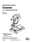
The proper intensity lev_ can be found by using your
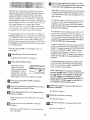
heart rate as a guide. The chart below shows recommended heart rates for fat burning and aerobic exercise.
HE,ART
FL&TE
TRAINING
ZONES
A3._O@IC
165
155
145
140
130
123
113
M.,._,( FA'T 8URN
145
138
130
125
118
110
103
F,_,T 8UF_N
125
20
!20
30
113
40
118
50
1(]3
60
55
70
g0
80
AIll
Exercise
If your goal is to strengthen your cardiovascular system, your exercise must be "aerobic." Aerobic exercise
is activity that requires large amounts of oxygen for
prolonged periods of time. This increases the demand
on the heart to pump blood to the muscies, and on the
lungs to oxygenate the bicod. For aerobic exercise,
adjust the speed and inc!ine of the treadmill until your
heart rate is near the highest number in your training
zone.
HOW TO MEASURE YOUR HEART RATE
To measure your
heart rate, stop exercising and place
two fingers on your
wrist as shown.
Take a six-second
heartbeat count, and
multiply the result by
ten to find your heart
rate. (A six-second count is used because your heart
rate drops quickly when you stop exercising.) if your
heart rate is too high or too low, adjust the speed or incline of the treadmill accordingly.
.
WORKOUT
GUIDELINES
A well-rounded workout includes the following three
important parts:
To find the proper heart rate for you, first find your age
at the bottom of the chart (ages are rounded off to the
nearest ten years). Next, find the three numbers at the
top of your age. The three numbers are your "training
zone." The lower two numbers are recommended
heart rates for fat burning; the higher number is the
recommended heart rate for aerobic exercise.
A Warm-up--Start
each workout with 5 to 10 minutes
of stretching and light exercise (see SUGGESTED
STRETCHES on page 15). A proper warm-up increases your body
temperature, heart rate, and circulation in preparation
for exercise.
Training Zone Exercise-After
warming up, increase
the intensity of your exercise until your pulse is in your
training zone for 20 to 60 minutes. (During the first few
weeks of your exercise program, do not keep your
pulse in your training zone for longer than 20 minutes.)
Breathe regulady and deeply as you exercise--never
hold your breath.
Fat Burning
To burn fat effectively, you must exercise at a relatively
low intensity level for a sustained period of time. During
the first few minutes of exercise, your body uses easily
accessible carbohydrate calories for energy. Only after
the first few minutes does your body begin to use
stored fat calories for energy. If your goal is to bum fat,
adjust the speed and incline of the treadmill until your
heart rate is near one of the lower two numbers in your
training zone.
A Cool-down--Finish
each workout with 5 to 10 minutes of stretching to cool down. This will increase the
flexibility of your muscles and will help to prevent postexercise problems.
21
EXERC
_E
F n',,} up !o five
FREQUENCY
b,e,:.k .....
_l..:..
STRETCHES
-, n:- ccrrac, 'o'-.... •
,,:"
" _u:.......
_
,".,love 51c',vly c..__,!; "_ u_.!. Toe Touch
each
Th,} key to success is to make exercise 4 regular and
enieyable pad of ycur everyday "'-_
To maintain or ".... '" vu:' ,.t.........
"' ""'
ton, ....
_...... ],_-_ throe
wor'xouts ......._ach
,v,,,,k ;*,'itS;"; c st one ca'. :f rest b{:i
....
,
L..
t,,veen workouts...',ftor a ,o,,,. , t,,s, you e'ay cam-
SUGGESTED
workouts
s_re:.c.nes s ShOWn _t the
,"i!;l!t.
....
Stretch
S_and with your k;:oes b..:_':_-"i:-':, ar'd s :,', y bend forward [r,_7,
'..cur hies. AI!c',v your ban,, ._:'-:s_su!ders :z "eJex as yc_ reach
.Jo,,vn :o,,vard you; t(; .'s as :2: 2s :esslble. -,sic for 15 counts. _l;en
:als:<. Repeat 3 fim_:s. S_r.'.:_':':s: _ams:r:'- as. sac',,:ci :<r,ees. :2.1:d
tack.
.-.'"Hamst_'ing
_Lretch
"'
'"
Sit ,,v_hone leg extended. 5: -_ :xe sc!e cf the opposite fact to'ward you and rest it 4gains: ::*e :'.set thigh :f your extended leg.
Reach toward your tc'_esas far as cossible. Ho!d for 15 counts, then
:eiax. Repeat 3 times for e2.c:" sg Stretches: Hamstrings, tower
:sack, and groin.
,3. Calf/AchiIies
/
/
Stretch
Vith one leg in front c_ the c:'-en reach for,'/ard and place your
:ands against a wail. Keep '..e:-: back !eg straight and your back
feat fiat on the floor. Bend ye.r front leg, lean forward and move
:.cur hips _cward the wall• Hcc: for 15 counts, then relax. Repeat 3
:[rases for each leg. To cause f:_:'::-erstretching of the achilles _encons, bend your back leg as .,,,eli.Stretches: CaJves, achilles tencons, and ankles•
4 Quadriceps
Stretch
".Vith one hand against a wail for balance, reach back and grasp
c:_e foot with your other hand. ---.ringyour heel as close to your butrocks as possible. Hold for 18 counts, then relax. Repeat 3 times
for both legs. Stretches: Queer!cons and i_ip muscles•
4-"
._. Inner Thigh Stretch
Sit with the soles of your feet together and your knees outward.
=:.il your feet toward your grcin area as far as possible. Hold for 15
:cunts, then relax. Repeat 3 times. Stretches: Quadriceps and hip
-" _:s/'h._s.
22
Y
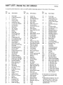
PART LIST--Model
No. 831.299450
RosooA
To locate the parts listed below, refer to the EXPLOOED DRAWING attached in the center of this manual.
Key
No.
Qty,
I
2
3
4"
1
1
4
I
5
6
7
8
g
10
11
12
13
14
15
16
17
18
19
20
21
22
23
24
25
25
27
28
29
30
31
32
33
34
35
36
37
38
39
40
41
42
43
44
45
46
47
48
49
50
51
52
53
Description
Key
No.
Motor Belt
54
Pulley/Flywheel/Fan
55
Motor Nut
56
MetoflPulley/
57
Flywheel/Fan
58
2 - Incline Motor Bolt
59
2
Incline Motor Spacer
60
1
_ncline Motor
61
1
Stop Bracket
62
1
Smatl Nut
63
2
Star Washer
64
1
Optic Switch
65
1
Frame
66
1
Small Bolt
67
1
_ncline Optic Disk
68
8
Incline MoOr Nut
69
4
Screw
70
4
Plastic Stand-Off
71
2
Hood Bracket {short)
72
2
Hood Bracket (long)
73
2
Warning Decal
74
1
Reed Switch
75
1
Reed Switch Clip
76
1
MotodController Wire *1
Controller
77*
1
Electronics Bracket
78
1
Circuit Breaker
79
1
Power Cord
80
1
Power Cord Grommet
81
1
On/Off Switch
82
1
Inlet Bracket
83
1
Incline Leg
84
2
Frame Pivot Bolt
2
Frame Pivot Spacer
85
1
Upright Wire Harness
86
1
Front Roller Ad i, Bolt
87
5
Handrail Washer/
88
2
Motor Tension Hut/
89
Front Roller Nut
90
4
Motor Bolt
91
4
Cap Screw
92
1
Left Foot Rail Cap
93
2
Foot Rail
94
1
Front RolledPulley
95
1
Magnet
96
4
Platform Screw
97
4
Isolator
98
4
Isolator Screw
99
15
Belly Pan Fastener
100
1
Shield
101
2
Belt Guide
102
1
Console Cover
103
1
Front Belly Pan
104
1
Power Supply
105
4
Cable Tie Clamp
106
Qty.
4
1
1
1
2
2
2
1
7
!
1
2
1
1
4
2
!
1
5
1
1
1
8
1
2
4
1
4
1
2
2
2
2
1
1
11
1
1
1
1
1
2
1
4
1
1
1
17
2
2
2
1
1
Description
Cable Tie
Walking Belt
20" Wire Harness
Rear Roller
Rear Isolator
Rear Foot
Rear Foot Screw
Ground Wire
Ground Wire Screw
Belly Pan
Rear Endcap
Rear Roller Adj. Bolt
Motor
Latch Decal
Rear Platform Screw
Catch Screw
Latch Catch
Walking Plat'form
8" Cable Tie
Jack
Motor Tension Bolt
Left Foot Rai! Insert
Reed Switch Screw/
Belly Pan Screw
Latch Assembly
Handrail Bolt
Long Screw
10' iFIT Wire
Motor Star Washer
Upright
Incline Leg Pivot BoLt
Incline Leg Pivot
Washer
Handrail
Wheel Bait
Console Base
Console
3/4" Screw
Key/Clip
Incline Motor Plate
Right Foot Rail Cap
Book Holder
Motor Hood
Front Wheel
Incline Motor Shield
Base Pad
12" Audio Wire
Upright Grommet
Allen Wrench
Short Screw
Handrail Insert
Extension Leg
Extension Leg Cap
Shock
Choke
23
Key
No.
Qty.
107
t 08
2
1
109
1
110
111
7
4
112
113
114
115
116
117
118
119
120
121
122
123
124
125
125"
2
2
4
2
2
2
4
4
2
2
2
1
2
1
2
127
125
129
130
131
132
t 33
134"*
135"*
136
137
138
139
#
#
#
#
#
.#
#
#
#
1
1
1
1
1
1
1
1
1
1
2
1
1
1
1
1
1
1
1
1
1
1
Description
Foam Grip
Upper Body Arm
w/Foam Grip {Left)
Upper Body Arm
w/Foam Grip (Right)
Washer
Resistance Bracket
Belt
Resistance Bolt
Resistance Bracket
Star Washer
Resistance Sleeve
Resistance Cone
Resistance Knob
Resistance Washer
Thrust Washer
Thrust Bearing
Spring Washer
Static Decal
Trim Guard
Interface Bracket
Photo Switch Harness
Extension Leg
Aesembly
Lock Knob
Lock Knob Bracket
Lock Knob Spring
Lock Pin Collar
Pin Clip
Lock Pin
iFIT.com CD
iF]T.com Module
iFiT.com Video
Rear Foot Spacer
Upright Base Endcap
Motor Tension Washer
Motor Tension Bushing
4" Red Wire, M/F
4" White Wire, M/F
8" Blue Wire, 2F
4" Blue Wire, 2F
4" Black Wire, 2F
4" Green Wire, F/Ring
8" Green Wire, F/Ring
5" Green Wire, 2 Ring
User's Manual
# These parts are not illustrated
* Includes all pa_s shown in the
box
**These parts are optional. For information about the iFIT.com roodule, iFIT.com CD's, or iFIT.com
videocassettes, call toll-free 1 800-884-0620.
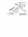
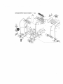
EXPLODED DRAWING--Model No. 831,299450
REMOVE THIS EXPLODED
DRAWING FROM
THE USER'S MANUAL. SAVE THE EXPLODED
DRAWING FOR FUTURE REFERENCE.
TO )d'talky E_
par_ ,,ho_ql 0n _
the U_E_S MANUAL
e_pk_
dnzw_,
ref e, _o the pART
UST
on _
23 ol
EXPLODED
DRAWING
-Model No. 831,299450
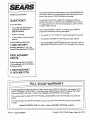
SFAUR6
The model number and serial number of your PROFORM" 635CW
treadmill are listed on a decal attached to the frame. See the front
cover of this manual to find the location ef the decal
Model No. 831.299450
QUESTIONS?
All replacement parts are available for immediate purchase or
special order when you visit your nearest SEARS Service Center.
To request service or to order parts by telephone, call the toll-free
numbers listed at the left.
If you find that:
• you need help assembling or
operating the PROFORM
635CW treadmill
When requesting help or service, or ordering parts, please be
prepared to provide the following information:
• a part is missing
• The NAME OF THE PRODUCT (PROFORM ° 635CW treadmill)
• or you need to schedule repair
service
• The MODEL NUMBER OF THE PRODUCT (831.299450)
call our toll-free HELPLINE
• The KEY NUMBER AND DESCRIPTION OFTHE PART (see the
EXPLODED DRAWING and PART LIST included in this manual)
1-800-736-6879
Monday-Saturday,
7 am-7 pm
Central Time (excluding holidays)
REPLACEMENT
PARTS
If parts become worn and need
to be replaced, call the following
toll-free number
1-800-FON-PART
(1-800-366-7278)
I
FULL 90 DAY WARRANTY
For 90 days from the date of purchase, if failure occurs due to defect in material or workmanship in this
SEARS TREADMILL EXERCISER, contact the nearest sEARS Service Center throughout the United
States and SEARS will repair or replace the TREADMILL EXERCISER, free of charge.
This warranty does.not apply when the TREADMILL EXERCISER
is usecl commercially or for rental pur-
poses.
This warranty gives you specific legal rights, and you may also have other rights which vary from state
to state.
SEARS, RDEBUCK .AND CO., DEPT. 817WA, HOFFMAN
Part No, 166673 RO800A
ESTATES, IL 60179
Printed in USA © 2000 Sears, Roebuck and Co.