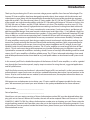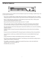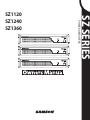
1
POWER POWER SZ SERIES POWER POWER AMPLIFERS SZ1120 SZ1240 SZ1360 7!2.).' 4/02%6%.4&)2%/23(/#+(!:!2$$/./453%4()30,5'7)4(!.%84%./.#/2$2%#%04!#,% /2/4(%2/54,%45.,%334(%",!$%3#!."%&5,,9).3%24%$4/02%3%.4",!$%%80/352% 4/02%6%.4&)2%/23(/#+(!:!2$$/./4%80/3%4()3!00,)!.#%4/2!)./2-/)3452% 4/026%.4%,%#42)#!,3(/#+-!4#(7)$%",!$%0,5'4/7)$%3,/4&5,,9).3%24 #!54)/. 2)3+/&%,%#42)#3(/#+ $/./4/0%. 4HISLIGHTNIGFLASHWITHARROW HEADSYMBOLWITHINANEQUI LATERALTRIANGLEISINTENDEDTO ALERTTHEUSERTOTHEPRESENCE OF UNINSULATED hDANGEROUS VOLTAGEv WITHIN THE PRODUCTS ENCLOSURE THAT MAY BE OF SUFFICIENT MAGNITUDE TO CONSTITUTE A RISK OF ELECTRIC SHOCKTOPERSONS 7ARNING4OREDUCETHERISKOF ELECTRIC SHOCK DO NOT REMOVE COVER OR BACK NO USER SERVICEABLEPARTSINSIDE2EFER SERVING TO QUALIFIED SERVICE PERSONNEL 4HEEXCLAMATIONPOINTWITHIN AN EQUILATERAL TRIANGLE IS INTENDEDTOALERTTHEUSERTO THE PRESENCE OF IMPORTANT OPERATING AND MAINTENANCE SERVICING INSTRUCTIONS IN THE LITERATURE ACCOMPANYING THEAPPLIANCE )-0/24!.43!&%49).3425#4)/.3 2EADTHESEINSTRUCTIONS +EEPTHESEINSTRUCTIONS (EEDALLWARNINGS &OLLOWALLINSTRUCTIONS $ONOTUSETHISAPPARATUSNEARWATER #LEANONLYWITHDRYCLOTH $ONOTBLOCKANYVENTIATIONOPENINGS)NSTALLINACCORDANCEWITHTHEMANUFACTURESINSTRUCTIONS $O NOT INSTALL NEAR ANY HEAT SOURCES SUCH AS RADIATORS HEAT REGISTERS STOVES OR OTHER APPARTUS INCLUDINGAMPLIFIERSTHARPRODUCEHEAT $O NOT DEFEAT THE SAFETY PURPOSE OF THE POLARIZED OR GROUNDING TYPE PLUG ! POLARIZED PLUG HAS TWO BLADESWITHONEWIDERTHANTHEOTHER!GROUNDINGTYPEPLUGHASTWOBLADESANDATHIRDGROUNDINGPRONG 4HEWIDEBLADEORTHETHIRDPRONGAREPROVIDEDFORYOURSAFETY)FTHEPROVIDEDPLUGDOESNOTFITINTOYOUR OUTLETCONSULTANELECTRICIANFORREPLACEMENTOFTHEOBSOLETEOUTLET 0ROTESTTHEPOWERCORDFROMBEINGWALKEDONORPINCHEDPARTICULARYATTHEPLUGSCONVENIENCERECEP TACLESANDATTHEPOINTWHERETHEYEXITFROMTHEAPPARATUS /NLYUSEATTACHMENTSACCESSORIESSPECIFIEDBYTHEMANUFACTURER 5SEONLYWITHTHECARTSTANDTRIPODBRACKETORTABLESPECIFIEDBYTHEMANUFAC TURER OR SOLD WITH THE APPARATUS 7HEN A CART IS USED USE CAUTION WHEN MOVINGTHECARTAPPARATUSCOMBINATIONTOAVOIDINJURYFROMTIPOVER 5NPLUGTHEAPPARATUSDURINGLIGHTENINGSORTORWHENUNUSEDFORLONGPERIODSOFTIME 2EFERALLSERVICINGTOQUALIFIEDPERSONNEL3ERVINGISREQUIREDWHENTHEAPPARATUSHASBEENDAMAGEDIN ANYWAYSUCHASPOWERSUPPLYCORDORPLUGISDAMAGEDLIQUIDHASBEENSPILLEDOROBJECTSHAVEFALLEN INTO THE APPARATUS HAS BEEN EXPOSED TO RAIN OR MOISTURE DOES NOT OPERATE NORMALLY OR HAS BEEN DROPPED 4HISAPPLIANCESHALLNOTBEEXPOSEDTODRIPPINGORSPLASHINGWATERANDTHATNOOBJECTFILLEDWITHLIQUID SUCHASVASESSHALLBEPLACEDONTHEAPPARATUS #AUTIONTOPREVENTELECRICALSHOCKMATCHWIDEBLADEPLUGWIDESLOTFULLYINSERT 0LEASEKEEPAGOODVENTILATIONENVIRONMENTAROUNDTHEENTIREUNIT Safety Instructions/Consignes de sécurité/Sicherheitsvorkehrungen/Instrucciones de seguridad WARNING: To reduce the risk of fire or electric shock, do not expose this unit to rain or moisture. To reduce the hazard of electrical shock, do not remove cover or back. No user serviceable parts inside. Please refer all servicing to qualified personnel.The lightning flash with an arrowhead symbol within an equilateral triangle, is intended to alert the user to the presence of uninsulated "dangerous voltage" within the products enclosure that may be of sufficient magnitude to constitute a risk of electric shock to persons. The exclamation point within an equilateral triangle is intended to alert the user to the presence of important operating and maintenance (servicing) instructions in the literature accompanying the product. Important Safety Instructions 1. Please read all instructions before operating the unit. 2. Keep these instructions for future reference. 3. Please heed all safety warnings. 4. Follow manufacturers instructions. 5. Do not use this unit near water or moisture. 6. Clean only with a damp cloth. 7.Do not block any of the ventilation openings. Install in accordance with the manufacturers instructions. 8. Do not install near any heat sources such as radiators, heat registers, stoves, or other apparatus (including amplifiers) that produce heat. 9. Do not defeat the safety purpose of the polarized or grounding-type plug. A polarized plug has two blades with one wider than the other. A grounding type plug has two blades and a third grounding prong. The wide blade or third prong is provided for your safety. When the provided plug does not fit your outlet, consult an electrician for replacement of the obsolete outlet. 10. Protect the power cord from being walked on and pinched particularly at plugs, convenience receptacles and at the point at which they exit from the unit. 11. Unplug this unit during lightning storms or when unused for long periods of time. 12.Refer all servicing to qualified personnel. Servicing is required when the unit has been damaged in any way, such as power supply cord or plug damage, or if liquid has been spilled or objects have fallen into the unit, the unit has been exposed to rain or moisture, does not operate normally, or has been dropped. ATTENTION: Pour éviter tout risque d’électrocution ou d’incendie, ne pas exposer cet appareil à la pluie ou à l’humidité. Pour éviter tout risque d’électrocution, ne pas ôter le couvercle ou le dos du boîtier. Cet appareil ne contient aucune pièce remplaçable par l'utilisateur. Confiez toutes les réparations à un personnel qualifié. Le signe avec un éclair dans un triangle prévient l’utilisateur de la présence d’une tension dangereuse et non isolée dans l’appareil. Cette tension constitue un risque d’électrocution. Le signe avec un point d’exclamation dans un triangle prévient l’utilisateur d’instructions importantes relatives à l’utilisation et à la maintenance du produit. Consignes de sécurité importantes 1. Veuillez lire toutes les instructions avant d’utiliser l’appareil. 2. Conserver ces instructions pour toute lecture ultérieure. 3. Lisez avec attention toutes les consignes de sécurité. 4. Suivez les instructions du fabricant. 5.Ne pas utiliser cet appareil près d’une source liquide ou dans un lieu humide. 6. Nettoyez l’appareil uniquement avec un tissu humide. 7.Veillez à ne pas obstruer les fentes prévues pour la ventilation de l’appareil. Installez l’appareil selon les instructions du fabricant. 8. Ne pas installer près d’une source de chaleur (radiateurs, etc.) ou de tout équipement susceptible de générer de la chaleur (amplificateurs de puissance par exemple). 9. Ne pas retirer la terre du cordon secteur ou de la prise murale. Les fiches canadiennes avec polarisation (avec une lame plus large) ne doivent pas être modifiées. Si votre prise murale ne correspond pas au modèle fourni, consultez votre électricien. 10. Protégez le cordon secteur contre tous les dommages possibles (pincement, tension, torsion,, etc.). Veillez à ce que le cordon secteur soit libre, en particulier à sa sortie du boîtier. 11. Déconnectez l’appareil du secteur en présence d’orage ou lors de périodes d’inutilisation prolongées. 12.Consultez un service de réparation qualifié pour tout dysfonctionnement (dommage sur le cordon secteur, baisse de performances, exposition à la pluie, projection liquide dans l’appareil, introduction d’un objet dans le boîtier, etc.). ACHTUNG: Um die Gefahr eines Brandes oder Stromschlags zu verringern, sollten Sie dieses Gerät weder Regen noch Feuchtigkeit aussetzen.Um die Gefahr eines Stromschlags zu verringern, sollten Sie weder Deckel noch Rückwand des Geräts entfernen. Im Innern befinden sich keine Teile, die vom Anwender gewartet werden können. Überlassen Sie die Wartung qualifiziertem Fachpersonal.Der Blitz mit Pfeilspitze im gleichseitigen Dreieck soll den Anwender vor nichtisolierter “gefährlicher Spannung” im Geräteinnern warnen. Diese Spannung kann so hoch sein, dass die Gefahr eines Stromschlags besteht. Das Ausrufezeichen im gleichseitigen Dreieck soll den Anwender auf wichtige Bedienungs- und Wartungsanleitungen aufmerksam machen, die im mitgelieferten Informationsmaterial näher beschrieben werden. Wichtige Sicherheitsvorkehrungen 1. Lesen Sie alle Anleitungen, bevor Sie das Gerät in Betrieb nehmen. 2. Bewahren Sie diese Anleitungen für den späteren Gebrauch gut auf. 3. Bitte treffen Sie alle beschriebenen Sicherheitsvorkehrungen. 4. Befolgen Sie die Anleitungen des Herstellers. 5. Benutzen Sie das Gerät nicht in der Nähe von Wasser oder Feuchtigkeit. 6. Verwenden Sie zur Reinigung des Geräts nur ein feuchtes Tuch. 7.Blockieren Sie keine Belüftungsöffnungen. Nehmen Sie den Einbau des Geräts nur entsprechend den Anweisungen des Herstellers vor. 8. Bauen Sie das Gerät nicht in der Nähe von Wärmequellen wie Heizkörpern, Wärmeklappen, Öfen oder anderen Geräten (inklusive Verstärkern) ein, die Hitze erzeugen. 9. Setzen Sie die Sicherheitsfunktion des polarisierten oder geerdeten Steckers nicht außer Kraft. Ein polarisierter Stecker hat zwei flache, unterschiedlich breite Pole. Ein geerdeter Stecker hat zwei flache Pole und einen dritten Erdungsstift. Der breitere Pol oder der dritte Stift dient Ihrer Sicherheit. Wenn der vorhandene Stecker nicht in Ihre Steckdose passt, lassen Sie die veraltete Steckdose von einem Elektriker ersetzen. 10. Schützen Sie das Netzkabel dahingehend, dass niemand darüber laufen und es nicht geknickt werden kann. Achten Sie hierbei besonders auf Netzstecker, Mehrfachsteckdosen und den Kabelanschluss am Gerät. 11. Ziehen Sie den Netzstecker des Geräts bei Gewittern oder längeren Betriebspausen aus der Steckdose. 12.Überlassen Sie die Wartung qualifiziertem Fachpersonal. Eine Wartung ist notwendig, wenn das Gerät auf irgendeine Weise, beispielsweise am Kabel oder Netzstecker beschädigt wurde, oder wenn Flüssigkeiten oder Objekte in das Gerät gelangt sind, es Regen oder Feuchtigkeit ausgesetzt war, nicht mehr wie gewohnt betrieben werden kann oder fallen gelassen wurde. PRECAUCION: Para reducir el riesgo de incendios o descargas, no permita que este aparato quede expuesto a la lluvia o la humedad. Para reducir el riesgo de descarga eléctrica, nunca quite la tapa ni el chasis. Dentro del aparato no hay piezas susceptibles de ser reparadas por el usuario. Dirija cualquier reparación al servicio técnico oficial. El símbolo del relámpago dentro del triángulo equilátero pretende advertir al usuario de la presencia de “voltajes peligrosos” no aislados dentro de la carcasa del producto, que pueden ser de la magnitud suficiente como para constituir un riesgo de descarga eléctrica a las personas. El símbolo de exclamación dentro del triángulo equilátero quiere advertirle de la existencia de importantes instrucciones de manejo y mantenimiento (reparaciones) en los documentos que se adjuntan con este aparato. Instrucciones importantes de seguridad 1. Lea todo este manual de instrucciones antes de comenzar a usar la unidad. 2. Conserve estas instrucciones para cualquier consulta en el futuro. 3. Cumpla con todo lo indicado en las precauciones de seguridad. 4. Observe y siga todas las instrucciones del fabricante. 5. Nunca utilice este aparato cerca del agua o en lugares húmedos. 6. Limpie este aparato solo con un trapo suave y ligeramente humedecido. 7.No bloquee ninguna de las aberturas de ventilación. Instale este aparato de acuerdo a las instrucciones del fabricante. 8. No instale este aparato cerca de fuentes de calor como radiadores, calentadores, hornos u otros aparatos (incluyendo amplificadores) que produzcan calor. 9. No anule el sistema de seguridad del enchufe de tipo polarizado o con toma de tierra. Un enchufe polarizado tiene dos bornes, uno más ancho que el otro. Uno con toma de tierra tiene dos bornes normales y un tercero para la conexión a tierra. El borne ancho o el tercero se incluyen como medida de seguridad. Cuando el enchufe no encaje en su salida de corriente, llame a un electricista para que le cambie su salida anticuada. 10. Evite que el cable de corriente quede en una posición en la que pueda ser pisado o aplastado, especialmente en los enchufes, receptáculos y en el punto en el que salen de la unidad. 11. Desconecte de la corriente este aparato durante las tormentas eléctricas o cuando no lo vaya a usar durante un periodo de tiempo largo. 12. Dirija cualquier posible reparación solo al servicio técnico oficial. Deberá hacer que su aparato sea reparado cuando esté dañado de alguna forma, como si el cable de corriente o el enchufe están dañados, o si se han derramado líquidos o se ha introducido algún objeto dentro de la unidad, si esta ha quedado expuesta a la lluvia o la humedad, si no funciona normalmente o si ha caído al suelo. Table of Contents Introduction. . . . . . . . . . . . . . . . . . . . . . . . . . . . . . . . . . . . . . . . . . . . . . . . . . . . . . . . . . . . . . . . . . . . . . . . . . . . 1 SZ Series Features. . . . . . . . . . . . . . . . . . . . . . . . . . . . . . . . . . . . . . . . . . . . . . . . . . . . . . . . . . . . . . . . . . . . . . . 2 SZ Series Layout - Front Panel . . . . . . . . . . . . . . . . . . . . . . . . . . . . . . . . . . . . . . . . . . . . . . . . . . . . . . . . . . . 3 SZ Series Layout - Rear Panel. . . . . . . . . . . . . . . . . . . . . . . . . . . . . . . . . . . . . . . . . . . . . . . . . . . . . . . . . . . . 4 Designing an Installation Plan. . . . . . . . . . . . . . . . . . . . . . . . . . . . . . . . . . . . . . . . . . . . . . . . . . . . . . . . . . . 5 Setting Up and Using Your SZ Series. . . . . . . . . . . . . . . . . . . . . . . . . . . . . . . . . . . . . . . . . . . . . . . . . . . . . 8 The SZ Series Protection Circuitry. . . . . . . . . . . . . . . . . . . . . . . . . . . . . . . . . . . . . . . . . . . . . . . . . . . . . . . . 9 SZ Series Connections. . . . . . . . . . . . . . . . . . . . . . . . . . . . . . . . . . . . . . . . . . . . . . . . . . . . . . . . . . . . . . . . . 10 SZ Series System Set Up. . . . . . . . . . . . . . . . . . . . . . . . . . . . . . . . . . . . . . . . . . . . . . . . . . . . . . . . . . . . . . . 11 SZ Series Input Wiring Guide . . . . . . . . . . . . . . . . . . . . . . . . . . . . . . . . . . . . . . . . . . . . . . . . . . . . . . . . . . 12 SZ Series Output Wiring Guide . . . . . . . . . . . . . . . . . . . . . . . . . . . . . . . . . . . . . . . . . . . . . . . . . . . . . . . . 13 Specifications. . . . . . . . . . . . . . . . . . . . . . . . . . . . . . . . . . . . . . . . . . . . . . . . . . . . . . . . . . . . . . . . . . . . . . . . . 14 Block Diagram. . . . . . . . . . . . . . . . . . . . . . . . . . . . . . . . . . . . . . . . . . . . . . . . . . . . . . . . . . . . . . . . . . . . . . . . 15 Copyright 2007 Printed December, 2007 v1.0 Samson Technologies Corp. 45 Gilpin Avenue Hauppauge, New York 11788-8816 Phone: 1-800-3-SAMSON (1-800-372-6766) Fax: 631-784-2201 www.samsontech.com Introduction Thank you for purchasing the SZ series constant voltage power amplifiers from Samson Technologies! The Samson SZ Series amplifiers have been designed to provide robust, clean output with low distortion and wide dynamic range, along with the dependability demanded by the most professional design engineers and audio installers. This manual covers three SZ series models, the SZ1120, the SZ1240 and the SZ1360. All of the models are single channel amplifiers with the SZ1120 reaching full power of 120 watts at 4 ohms, the SZ1240; 240 watts at 4 ohms, and the SZ1360; 360 watts at 4 ohms. The amplifiers can also run at 25, 70 or 100 volts thanks to their internal, high performance matching transformers making them ideal solution for Constant Voltage systems. The SZ series are enclosed in a convenient 2 rack-space chassis and feature reliable linear amplifier design. Rear panel controls include input Level Adjust from –12 to 0 dB and a High Pass Filter at 400Hz to use with announcement horn speakers. A front panel Signal, Peak and Protection LED indicators to help you set the correct operating levels. Standard XLR Input and Link connectors, plus Euroblock speaker output connectors are provided to insure easy connections and maximum flexibility. To keep the SZ series amplifiers running cool, their designs employ internal wind tunnels with forced-air cooling via an internal fan, greatly reducing the chance of thermal and overheating problems. Multi-stage protection for power-up, over-heating, over-current, short circuit, low output impedance and DC voltage, assures high reliability under the most demanding situations. The SZ series amplifiers are road tough with their all steel chassis, 19-inch rack mount design and convenient carry handles facilitating easy installation in any rack. Optimized for commercial installations including schools, houses of worship, office buildings and live sound venues, the SZ series amplifiers will deliver reliable power. The SZ Series’ advanced technology, clear sound and reliable performance makes them ideal for any small public address or distributed sound system installation. In this manual, you’ll find a detailed description of the features of the SZ series amplifers, as well as a guided tour through the front and rear panels, step-by-step instructions for using the unit, suggested applications and full specifications. You’ll also find a warranty card enclosed—please don’t forget to fill it out and mail it so that you can receive online technical support and so we can send you updated information about other Samson products in the future. Also, be sure to check out our website (www.samsontech.com) for complete information about our full line of Samson audio products. With proper care and adequate air circulation, your SZ series amplifer will operate trouble free for many years. We recommend you record your serial number in the space provided below for future reference. Serial number: _______________________________ Date of purchase: _____________________________ Should your unit ever require servicing, a Return Authorization number (RA) must be obtained before shipping your unit to Samson. Without this number, the unit will not be accepted. Please call Samson at 1-8003SAMSON (1-800-372-6766) for a Return Authorization number prior to shipping your unit. Please retain the original packing materials and if possible, return the unit in the original carton and packing materials. If you purchased your Samson product outside the United States, please contact your local distributor for warranty information and service. SZ Series Features POWER The Samson SZ Series power amplifiers have been developed using the latest technology in amplifier design. Here are some of their main features: • Each SZ Series amplifier delivers reliable, clean power operation at 70/100 volts and 4 Ohms, with their rated power output of 120 watts for the SZ1120, 240 watts for the SZ1240 and 360 watts for the SZ1360. • Built-in 70/100 volt output transformers with flat frequency response from 70Hz to 18kHz provide constant voltage for distributed speaker systems. • Rear panel level control allows precision adjustments from -12 to 0dB. • Clean, crisp sound - Impressive audio specifications such as 0.04% THD, dynamic range of 105 dB, crosstalk of 80 dB, and frequency response of 70Hz to 18kHz guarantee ultra-clean sound quality. • LED signal indicators continuously display power output levels and allow you to correct for overloading (clipping) conditions. • Forced air cooling via internal fan provides reliable performance without thermal and overheating problems. • Protection circuitry (with dedicated LEDs) that guards against overheating or faulty wiring conditions. • Input connection is made using a standard male XLR connector to accommodate balanced signal sources. • Output connections are made using Euroblock connectors which accept 12 gauge wire. • The SZ Series can be mounted in any standard 19" rack (taking just two rack spaces), making it easy to integrate into any fixed or traveling PA rig. • The amplifiers are enclosed in a ruggedly constructed (all-steel chassis with a sleek, black finish), standard 2-space 19-inch rack mount unit. • Extended three-year warranty. SZ Series Layout - Front Panel 1 2 3 4 5 1 POWER 7 6 1: Handle - For easy transport while carrying, or while rack mounting, the SZ amplifier features two heavy duty, die cast handles located conveniently on the left and right side of the front panel. 2: Fan Vent - The SZ series amplifers stay cool thanks to the forced-air cooling vents. Cool air is drawn through the front panel fan, reducing the temperature of the internal components while forcing the heat out the rear vents. 3: Protection LED - This goes on for approximately five seconds whenever the SZ Series is powered on and then turns off. The Protection LED will also light when overheating or other severe problems occur (see page 9 in this manual for more information). It is normal for the Protection LED to fade slowly when the amp is powered off. When lit, no signal is provided to any connected speakers, thus muting them and preventing any “thump” from occurring. For a complete description of the conditions under which this light turns on, see the section entitled “The SZ Series Protection Circuitry” on page 9 of this manual. 4: CLIP LED - The CLIP segment lights whenever the amplifier is outputting signal at full strength. For the best signal-to-noise ratio, the CLIP segment should light occasionally during peak levels; if it lights frequently, you may be overloading the amplifier and a distorted (“clipped”) signal is probably being output. 5: Power switch - Use this to power the SZ Series on or off. The internal LED lights whenever the SZ Series is powered on. 6: -20 dB LED - The -20dB LED lights whenever the output signal is 20dB below full power. 7: Signal LED - The SIGNAL LED lights whenever output signal is present. SZ Series Layout - Rear Panel 1: AC INPUT - Connect the supplied heavy-gauge 3-pin “IEC” power cable here. 2: DC 24V INPUT – A two circuit Euroblock socket is provided for connecting 24 volt emergency back-up power. 3: CONSTANT VOLTAGE (output connector) - Use this Euroblock to connect the amplifier to one of the 25, 70 and 100 volt outputs if you are using a constant voltage system. See page 13 in this manual for more information about wiring and interconnection instructions. 4: LOW-Z (output connector) - Use this Euroblock to connect the amplifier to a 4 ohm speaker. See page 13 in this manual for more information about wiring and interconnection instructions. 5: LEVEL ADJUST- This control knob provides input level adjustment from -12dB to 0dB. 6: HPF (HIGH PASS FILTER) – Selectable High Pass, or low cut, filter at 400Hz used when powering outdoor announcement horn speakers. 7: INPUT – XLR connector for balanced line level input. 8: LINK – Female XLR connector for connecting additional amplifiers. 9: GROUND LIFT - Used to float the audio ground from the chassis ground. 10: Rear Vents – Used in combination with the internal fan and front vents to dispel warm air ensuring reliable operation. WARNING!: Each of the SZ Series amplifiers can run only one output configuration at the same time. Operating SZ series amplifers using 4 ohm and 25, 70 or 100 volt concurrently may cause damage to the amplifier or connected speakers, and may void your warranty. Designing an Installation Plan Designing an Installation Plan If you are a professional installer, you’ll probably want to skip over this section, however if you are setting up your system for the first time, this section can help make your installation a little bit easier. Before you start plugging, stripping and connecting wires, it a good idea to have a clear installation plan. To create your installation plan, you need to consider several design parameters including what sound sources will be used, if announcement paging in necessary, which rooms need to have sound, if remote volume control is required, which type of speakers will do the best job for the room they are covering, and your wiring plan. Selecting the Sound Sources If you are using multiple sound sources, you'll need some type of mixer and for fixed installations, a zone mixer like the Samson S zone is ideal. The S zone provides four input channels with the ability to connect up to six input sources. On input Channel’s 1 and 2 there is an input for connecting microphones with phantom power to operate condenser type mics. The S zone also has a special Ducking feature so when you speak into the microphone, the volume of the music is automatically lowered. You can connect line level signals on all four input channels, so signals from TAPE, CD, DVD or Karaoke players, Audio/Video TV monitors, Radio Tuners, DJ mixers or any other line level device can be used as a sound source. You may also be able to connect the output from a home hi-fi receiver if it’s equipped with a line level output. For example, in a small to medium size restaurant, you may want background music from a CD in one room, Disco Karaoke in another room, the ability to have a hostess paging parties for their tables and a cook paging a waitress to pick up an order. The Samson S zone can accomplish all of this easily. Creating the Audio Zones You can create separate audio environments using up to four S zone’s outputs, each connected to the input on the SZ series amplifier. You can connect one or more speakers with a total load impedance of 4 ohms or more to the SZ Series amplifier's output. Obviously, (or perhaps not so obviously) we call an output a zone on the S zone, but a zone is also the area where you want to have sound. So, think about where you want to distribute the sound. The SZ Series amplifiers and S zone can accomplish all of this easily. In addition, the S zone let’s you easily connect a remote control level for each of the zones, so you can control the volume in the room even if the audio equipment is located somewhere else. Designing an Installation Plan Now, take some time to consider where you need to have sound in your particular installation. After you have decided where you need to create sound zones, you can consider your speaker selection, but first decide where you are going to locate your equipment rack. Using Active Speakers In a larger installation, you may use a combination of passive speakers connected to your SZ Series amplifier along with some active, or self powered speakers in a different zone. When using active speakers, you can connect the S zone’s outputs using the balanced line level signals. In this case, you will run line level signal from the S zone’s Zone Output over the long wire run to the input of the powered speaker located in the sound zone. For more information on wiring for balanced signals, see the Input Wiring Guide on page 12 of this manual. Locating Your Equipment Rack Since the SZ series amplifers and S zone are standard 19-inch rack mount devices, you should consider using an equipment rack, such as one of the Samson SRK series. To select a good location for your equipment rack, you should consider several points including the proximity to each of the sound zones, if the users need to access the gear to change CD’s or to adjust a volume level and if you have a convenient location to the electrical service, to name a few. You will need to consider the length of wire runs and routing necessary to make the connections from the equipment rack to the various sound zones. Depending on the speakers you choose, and the length of cable runs you need to make, you may choose to run speaker level or line level to the sound zones. If you are using passive (non-powered) speakers, you will need to connect the output channels of the S zone to an input channel of the SZ amplifier and run speaker wire, however you need to be careful to pay attention to the wire gauge and total length of the wire run. If you are using powered (active) speakers, you can run long distances using the balanced outputs directly from the S zone. Since the SZ Series' and S zone's inputs and output connections are terminated using Euroblock connectors, the wiring can easily be run in advance of the equipment installation. Using Passive Speakers If you are using passive (un-powered) speakers, you need to first decide where you will place your power amplifier. If the speakers in a particular sound zone are less than 100 feet away, you can locate your SZ series power amplifier in the same rack as the S zone and connect the speaker wires from the amplifier to your sound zone. NOTE: This type of wiring is known as "home-run wiring" since you are making direct connections from the amplifiers in the equipment rack to the speakers located in the sound zone room. In this case, you would connect the S zone’s Zone Output to the SZ Series Input and then run the speaker wires to the passive speakers. Be sure to check the impedance of the speakers you are using. SZ Series amplifiers can run at 4 ohms, so connect one 4 ohm or two 8 ohm speakers on each SZ output channel. If the speakers in a particular sound zone are further than 100 feet, you should consider placing the amplifier in the same room as the sound zone or use a constant voltage speaker system. Another type of installation is one that uses speakers and amplifiers (like the SZ Series) with 70-volt transformers, which are commonly referred to as Constant Voltage systems. The benefit of a Constant Voltage system is you can run long lengths of wire and have many speakers connected to a single amplifier. You can also balance the level of each speaker by using one of the available transformer settings. The SZ series amplifiers are ideal for this thanks to their built-in 25/70/100 volt output transformers. Using A Constant Voltage Speaker System If your installation requires multiple speakers and long cable runs, you should consider running a 70 volt, constant voltage system. Constant voltage systems became the installation standard in the mid-1900’s offering a cost effective solution for installations using multiple speakers and long cable runs. The idea was borrowed from the cross-country power grid where voltage is stepped up and therefore the current is reduced allowing huge amounts of power to run over long distances on relatively small, lower cost cable. Ultimately the voltage is stepped down and delivered to the customer over a short, heavy gauge cable. Selecting Speakers for Each Zone To select the speakers, you need to consider a few important issues, like where you are going to place your power amplifiers, using powered or un-powered speakers, or if you need to run a 70-volt distributed sound system. The following sections provide a brief overview on how to connect active and passive speakers or a constant voltage system in a typical installation. IMPORTANT NOTE: Only licensed and insured professional sound contractors should install Constant Voltage Systems. Samson assumes no liability for any installation. Designing an Installation Plan Using A Constant Voltage Speaker System - continued The same principle is applied in constant voltage audio systems where a transformer is connected to the amplifier’s output to step up the voltage while lowering the output current, which allows you to use long runs of lower gauge wire to connect to a series of speakers with step down transformers. For further cost savings, the 70 volt standard was adopted in the US since UL requires the use of conduit on line over 100 volts peak. In addition to 70 volt operation, the SZ Series amplifiers can also operate 100 volt systems which is a standard in Europe. Commercial sound systems, like those installed in schools, office buildings and restaurants commonly make use of constant voltage distributed sound systems when a large number of ceiling speakers are used to cover several different sound zones. Another example is connecting four of the Samson dB300i with the transformers wired for 25 watts to each channel of the SZ Series amplifier. Following the wiring diagram on the rear of the dB300i, connect the ground to Common, the Hot lead to 70 volt input, and finally, run a jumper from 8 ohms to the 25 watt connection as shown in the diagram below. Set up each of the dB300i the same way so that the four connected speakers equal 100 watts. Today, there are a large number of installation speakers available from various manufacturers that include onboard transformers for constant voltage systems. Many of these models, like the Samson dB300i, include selectable power taps on the transformer allowing you to distribute the power efficiently through the number of installed speakers and also adjust some speakers to different output levels(see diagram below). The SZ Series amplifiers have built in transformers that step up the output voltage and reduce the current allowing you to connect to a series of speakers with step down transformers over long cable runs. A simple way to think about using constant voltage is to divide the total watts available by the number of speakers you want to use. You could also add up the speaker's step up transformer wattage to equal 100 watts or less. For example, if you want to use ten ceiling speakers on one SZ1120 amplifier, use a ceiling speaker with a 12-watt transformer tap (120 watts divided by 10 speakers equals 12-watts per speaker). The dB300i's rear panel is configured for 70 volt, 25 watt operation. Now connect the four speakers to each of the SZ1120's output as shown in the diagram below. Typical ceiling speaker with onboard transformer and six power taps. These power taps also control volume level for sound balancing. Zone 2 Setting Up and Using Your SZ Series Setting up your SZ Series is a simple procedure which takes only a few minutes: 1. Remove all packing materials (save them in case of need for future service) and decide where the amplifier is to be physically placed—it can be used free-standing or mounted in a standard 19” rack, requiring only two rack spaces. When installed, make sure that both the front and rear panels are unobstructed and that there is good ventilation around the entire unit (we recommend the use of spacer panels, especially if multiple amplifiers are used in a rack. 2. Make the speaker connections, using the Euroblock output connectors on the rear panel. It is never a good idea to power up any amplifier that is not connected to loudspeakers. When operating using the 4 ohm output, any loudspeakers with a minimum impedance load of 4 ohms (that is, 4 ohms or greater) can be used. Make sure the 4 ohm terminal is connected to the positive input of the speaker and the COM (ground) terminal is connected to the negative input of the speaker. For 25 volt operation, connect the positive input of the speaker to the 25 volt terminal and connect the negative input to the COM (ground) terminal. For 70 volt operation, connect the positive input of the speaker to the 70 volt terminal and connect the negative input to the COM (ground) terminal. For 100 volt operation, connect the positive input of the speaker to the 100 volt terminal and connect the speaker's negative input to the COM (ground) terminal. See the Output Wiring Guide on page 13 for more information. 4. If you are using outdoor horn speakers, switch on the High Pass Filter. HPF 400Hz OFF ON 5. On the rear panel of the SZ Series, turn the input Adjust fully counterclockwise (to the “-12dB” setting). Then connect the supplied heavy-gauge 3-pin “IEC” cable to the rear panel IEC connector and to any grounded AC outlet. INPUT ADJUST -12dB 0dB 6. Press the front panel Power switch in order to turn on the SZ Series. The Power LED will light and the Protection LED will go on. POWER After approximately five seconds, the Protection LED will go off. PROTECT CLIP -20 dB SIGNAL 3. Next, make the signal input connections, using the XLR input connectors on the rear panel. If your mixer has balanced outputs, we recommend the use of three-conductor cabling and connectors (unbalanced two-conductor connections can also be used, but you’ll get better signal quality and less outside noise and hum if you use balanced lines). See the Input Wiring Guide on page 12 for more information. INPUT 7. Apply an input signal to the SZ Series at or about +4dBu (if sending signal from a mixer, drive the output meters at approximately 0 VU). While the input signal is present, slowly raise the Input Adjust control until the desired sound level is achieved. The SIGNAL and CLIP LED indicators will show you the continuous power output of the SZ Series as signal is being passed. For the best signal-to-noise ratio, the SZ Series should normally be run with the Input Adjust control at or near maximum (fully clockwise, at the “0dB” position) and the CLIP segments should light occasionally (but not frequently) during peak levels. If you are using a mixer that has a master output level control, use it to attenuate the signal as necessary to achieve the desired speaker level. PROTECT If you are using more than one amplifier, you can use the LINK connector to the input of the second amplifer. CLIP -20 dB LINK SIGNAL If you encounter difficulty with any aspect of setting up or using your SZ Series, contact your local Samson dealer. If purchased in the United States, you can call Samson Technical Support (1-800372-6766) between 9 AM and 5 PM EST. The SZ Series Protection Circuitry As noted in the “Guided Tour” section of this manual, the SZ Series front-panel Protection LED indicates the activity of the relay speaker connection circuitry. When the Protection LED is lit, this circuitry is active, and all connected speakers are muted. The following conditions will cause the Protection LED to go on: PROTECT CLIP -20 dB • Initial power-up: For approximately five seconds after initial power-up, the protection circuitry is activated and the speaker outputs are muted. If everything is operating normally, the SZ Series begins delivering signal to connected speakers (at which point you’ll hear the click). It is normal for the Protection LED to fade gradually after the amplifier is powered off. WARNING: If the Protection LED fails to go out (and you fail to hear the accompanying audible click) approximately five seconds after power-up, turn the SZ Series off immediately and check all external devices and wiring for possible shorts or other defects. • Overheating: A temperature sensing device in the SZ Series will cause the protection circuitry to be activated (and the Protection LED to go on) whenever the operating temperature of the unit rises above a safe level. To guard against this problem, make sure the SZ Series receives adequate ventilation on all sides and that both the front and rear panels are unobstructed. • Severe over current conditions: This occurs whenever the signal being output from the SZ Series rises to a level above 20% THD (Total Harmonic Distortion). • Shorted speaker cables: This will occur if, due to faulty wiring, the hot and ground signals being output by the SZ Series are shorted to one another. • Output impedance drops below 2 ohms: This can occur if the SZ Series is connected to inappropriate speaker systems (see the “Setting Up and Using Your SZ Series” section on page 10 in this manual for more information). In general, any time the Protection LED lights up (other than during the approximately five seconds following initial power-up), there is reason to be concerned. If this occurs, turn the SZ Series off immediately and carefully check all wiring and external devices in order to locate and correct the condition that caused the LED to light up in the first place. For further assistance, contact your local Samson dealer. If purchased in the United States, you can call Samson Technical Support (1-800-372-6766) between 9 AM and 5 PM EST. SIGNAL SZ Series Connections The following diagrams illustrate various wiring set ups for 4 ohm, 8 ohm and 70 Volt operation. 8 Ohm 4 Ohm 8 Ohm 8 Ohm Operation (One 8 Ohm speaker per amplifer) 4 Ohm 4 Ohm Operation (Two 8 Ohm speakers per amplifer) 70 Volt Operation (Four speakers per amplifer with their line transformers set to 25 watt) 10 SZ Series System Set Up The following is a typical constant voltage system setup for a small restaurant using four SZ1120 power amplifiers along with an S zone feeding several audio zones with paging and music. The first two SZ amps are connected to four wall-mounted speakers in each of the Dining Rooms with their transformers set to a 25 watt tap. The third SZ amp powers two speakers in the outside Bar area with their transformers set to 50 watt. (The db300i's are specially treated so they're suitable for indoor and outdoor use.) The fourth SZ amp powers small speakers in the lobby with a 12 watt tap. 11 SZ Series Input Wiring Guide SZ Series Input Wiring Guide There are several ways to interface the SZ Series amplifers, depending on your exact system set-up. Follow the cable diagrams below for connecting to the input of your amplifier. Male XLR to Female XLR (balanced) Hot (2) Common (1) 1 2 3 End View 2 Common Hot Hot Common (1) Hot (2) Common 1 1 3 2 2 3 Solder Points Cold (3) Cold Male XLR Solder Points Cold 1 3 End View Cold (3) Female XLR Male XLR to 1/4-inch (Balanced) Male XLR to1/4-inch (Unbalanced) Tip (signal) Hot (2) Common (1) 1 2 3 End View 2 Signal Tip (signal) 1 3 Cold (Pin 3) (no connection) Solder Points Cold (3) Ground Male XLR Sleeve (ground) Sleeve (ground) Male XLR to RCA (Unbalanced) Tip (signal) Hot (2) Common (1) 1 2 3 End View 2 Tip (signal) 1 3 Solder Points Cold (3) Cold (Pin 3) (no connection) Sleeve (ground) Male XLR Sleeve (ground) 12 SZ Series Output Wiring Guide SZ Series Output Wiring Guide There are several ways to interface the SZ Series amplifers, depending on your exact system set-up. Follow the cable diagrams below for connecting to the output of your amplifier. 4 and 8 Ohm Wiring Guide 25 Volt Wiring Guide 70 Volt Wiring Guide 100 Volt Wiring Guide Follow the guidelines below to select the appropriate size wire based on the distance from the amplifier to the speaker. The wire sizes apply to the 4-ohm tap. Distance Wire Size Up to 25 ft. 16 AWG 26~40 ft. 14 AWG 41~60 ft. 12AWG 61~100 ft. 10AWG 101ft~150 ft. 8AWG 151~200 ft. 6AWG NOTE : Custom wiring should only be performed by licensed and insured, qualified personnel. Class 2 wiring is required. CAUTION : Never use shielded cable for output power wiring SHOCK HAZARD SYMBOL WARNING!!! - PAY ATTENTION TO THE WARNING SYMBOL AND AVOID ELECTRICAL SHOCK. DO NOT HOLD OR TOUCH THE COMMON AND 70 OR 100 VOLT WIRE CONNECTION WHILE OPERATING THE AMPLIFIER. 13 Specifications Specifications Rated Output (at T.H.D 1.0%, 1kHz) SZ1120 SZ1240 SZ1360 120Watt 240Watt 360Watt Gain Control -12dB ~ 0dB Input Sensitivity (at Balanced line) 1.0 ± 0.1Vrms / 10Kohm High-pass Filter(at 400Hz) -3dB Frequency Response +1.5 / -3 dB at 70Hz~18kHz S/N Ratio Better than 90dB T.H.D at 1/2 rated output, 1kHz Less than 1.0% Cooling Variable speed fan Operating Temperature/Humidity 0°~40°C at 95% non-condensing Power Consumptions at full power SZ1120 SZ1240 SZ1360 Power Requirement 185W 361W 525W AC100V~240V, 50/60Hz and/or DC24V DC Power battery back-up power specification: Dimensions (Width/Height/Depth) 482 mm X 88 mm X 340 mm Net Weight SZ1120 SZ1240 SZ1360 25.6 lb. (11.65kg) 30.5 lb. (13.87kg ) 33.4 lb.(15.16kg) Specifications are subject to change without notice. 14 Block Diagram 15 Samson Technologies Corp. 45 Gilpin Avenue Hauppauge, New York 11788-8816 Phone: 1-800-3-SAMSON (1-800-372-6766) Fax: 631-784-2201 www.samsontech.com