1
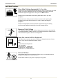
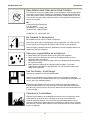
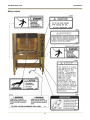
Gas Rotisserie Oven
MODEL DRG-40
Service Manual
Serial Numbers 120170 and Higher
Warranty Information
LIMITED ONE YEAR WARRANTY
BKI (The "Company") warrants to the original purchaser that at time of shipment from the
Company factory, this equipment will be free from defect in materials and workmanship. Written
notice of a claim under this warranty must be received by the Company within ONE YEAR from
the date of installation, but no longer than ONE YEAR AND THREE MONTHS from date of
shipment from the factory. Defective conditions caused by abnormal use or misuse, lack of or
improper maintenance, damage by third parties, alterations by unauthorized personnel, acts of
God, failure to follow installation and/or operating instructions, or any other events beyond the
reasonable control of the Company will NOT be covered under this warranty. The obligation of
the Company under this warranty shall be limited to repairing or replacing (at the option of the
Company) any part, with the exception of lamps, fuses, and glass (which are not covered under
warranty), which is found defective in the reasonable opinion of the Company. Any part found
defective by the Company will be repaired or replaced without charge F.O.B. factory,
Simpsonville, South Carolina or F.O.B. authorized BKI Distributor. The Company and/or its
authorized representatives will assume the normal replacement labor expense for the defective
part for the period of the warranty as stated above, excluding travel and/or other expenses
incidental to the replacement of the defective part, where replacement work is performed during
standard business hours and not subject to overtime, holiday rates, and/or any additional fees. IN
NO EVENT SHALL THE COMPANY BE LIABLE FOR LOSS OF USE, LOSS OF REVENUE OR
LOSS OF PRODUCT OR PROFIT OR FOR INDIRECT OR CONSEQUENTIAL DAMAGES
INCLUDING BUT NOT LIMITED TO, FOOD SPOILAGE OR PRODUCT LOSS. WARRANTY
DOES NOT COVER GLASS BREAKAGE. THE ABOVE WARRANTY IS EXCLUSIVE AND ALL
OTHER WARRANTIES, EXPRESS OR IMPLIED, ARE EXCLUDED INCLUDING THE IMPLIED
WARRANTIES OF MERCHANTABILITY AND FITNESS FOR A PARTICULAR PURPOSE.
REPLACEMENT PARTS
Any appliance replacement part, with the exception of lamps, fuses, and glass, which proves to
be defective in material or workmanship within ninety (90) days of installation will be replaced
without charge F.O.B. Factory, Simpsonville, SC or F.O.B. authorized BKI Distributor. The user
shall have the responsibility and expense of removing and returning the defective part to the
Company as well as the cost of reinstalling the replacement or repaired part.
The purchaser must post, in a prominent location, instructions to be
followed in the event the user smells gas. This information shall be
obtained by consulting the local gas supplier.
FOR YOUR SAFETY
Do not store or use gasoline or other flammable vapors or liquids
in the vicinity of this or any other appliance.
Improper installation, adjustment, alteration, service or
maintenance can cause property damage, injury or death. Read
the installation, operation and maintenance instructions
thoroughly before installing or servicing this equipment.
Gas Rotisserie Oven
Table of Contents
Table of Contents
Table of Contents .................................................................................................................................................... 1
Introduction.............................................................................................................................................................. 2
Safety Precautions ................................................................................................................................................ 2
Safety Signs and Messages ............................................................................................................................. 2
Safe Work Practices ......................................................................................................................................... 3
Safety Labels .................................................................................................................................................... 6
Installation................................................................................................................................................................ 8
Inspection for Shipping Damage ........................................................................................................................... 8
Preparation............................................................................................................................................................ 8
Location and Clearance ........................................................................................................................................ 9
Installation Procedure............................................................................................................................................ 9
Gas Conversion Instructions ............................................................................................................................... 10
Replacement Parts ................................................................................................................................................ 11
Assemblies .......................................................................................................................................................... 11
Accessories & Components ................................................................................................................................ 25
Wiring Diagrams .................................................................................................................................................... 27
Appendix A............................................................................................................................................................. 31
Notes....................................................................................................................................................................... 32
1
Gas Rotisserie Oven
Introduction
Introduction
Your DRG-40 is a computer controlled gas fired rotisserie oven. It utilizes a double revolving rotor system to
ensure even product cooking. The unit contains a single stage cook and hold computer with 5 customizable cook
programs. Electrical controls are provided for powering the unit, turning on inside lights, igniting upper/lower
burners, turning the rotors, filling the water bath and resetting the unit. A manual lever is supplied for draining
water from the water bath. The rotor system is removable to allow for easy maintenance and cleaning.
The BKI name and trademark on this unit assures you of the finest in design and engineering -- that it has been
built with care and dedication -- using the best materials available. Attention to the operating instructions
regarding proper installation, operation, and maintenance will result in long lasting dependability to ensure the
highest profitable return on your investment.
PLEASE READ THIS ENTIRE MANUAL BEFORE OPERATING THE UNIT. If you have
any questions, please contact your BKI Distributor. If they are unable to answer your
questions, contact the BKI Technical Service Department, toll free: 1-800-927-6887.
Outside the U.S., call 1-864-963-3471.
Safety Precautions
Always follow recommended safety precautions listed in this manual. Below is the safety alert symbol. When you
see this symbol on your equipment, be alert to the potential for personal injury or property damage.
Safety Signs and Messages
The following Safety signs and messages are placed in this manual to provide instructions and identify specific
areas where potential hazards exist and special precautions should be taken. Know and understand the meaning
of these instructions, signs, and messages. Damage to the equipment, death or serious injury to you or other
persons may result if these messages are not followed.
This message indicates an imminently hazardous situation which, if not avoided, will
result in death or serious injury.
This message indicates a potentially hazardous situation, which, if not avoided, could
result in death or serious injury.
This message indicates a potentially hazardous situation, which, if not avoided, may
result in minor or moderate injury. It may also be used to alert against unsafe practices.
This message is used when special information, instructions or identification are required
relating to procedures, equipment, tools, capacities and other special data.
2
Gas Rotisserie Oven
Introduction
Safe Work Practices
Wear Safe Clothing Appropriate To Your Job
Always wear your insulated mitts when handling hot racks or touching any hot metal
surface. If you lose or damage your mitts, you can buy new ones at your local
restaurant equipment supply store or from your local BKI Distributor.
Always wear non-skid shoes when working around the oven or any other
equipment.
Never wear loose clothing such as neckties or scarves while operating this
equipment. Keep loose hair tied back or in a hair net while operating this
equipment.
Always wear appropriate personal protection equipment during the cleaning
process to guard against possible injury from hot cleaning solution.
Beware of High Voltage
This equipment uses high voltage. Serious injury can occur if you or any untrained
or unauthorized person installs, services, or repairs this equipment. Always Use an
Authorized Service agent to Service Your Equipment.
Keep this manual with the Equipment
This manual is an important part of your equipment. Always keep it near for easy
access. If you need to replace this manual, contact:
BKI
Technical Services Department
P.O. Box 80400
Simpsonville, S.C. 29680-0400
Or call toll free: 1-800-927-6887
Outside the U.S., call 864-963-3471
Protect Children
Keep children away from this equipment. Children may not understand that this
equipment is dangerous for them and others.
NEVER allow children to play near or operate your equipment.
3
Gas Rotisserie Oven
Introduction
Keep Safety Labels Clean and in Good Condition
Do not remove or cover any safety labels on your equipment. Keep all safety labels
clean and in good condition. Replace any damaged or missing safety labels. Refer
to the Safety Labels section for illustration and location of safety labels on this unit.
If you need a new safety label, obtain the number of the specific label illustrated on
page 6, then contact:
BKI
Technical Services Department
P.O. Box 80400
Simpsonville, S.C. 29680-0400
Or call toll free: 1-800-927-6887
Outside the U.S., call 864-963-3471
Be Prepared for Emergencies
Be prepared for fires, injuries, or other emergencies.
Keep a first aid kit and a fire extinguisher near the equipment. You must use a 40pound Type BC fire extinguisher and keep it within 25 feet of your equipment.
Keep emergency numbers for doctors, ambulance services, hospitals, and the fire
department near your telephone.
Know your responsibilities as an Employer
• Make certain your employees know how to operate the equipment.
• Make certain your employees are aware of the safety precautions on the
equipment and in this manual.
• Make certain that you have thoroughly trained your employees about operating
the equipment safely.
• Make certain the equipment is in proper working condition. If you make
unauthorized modifications to the equipment, you will reduce the function and
safety of the equipment.
Use Gas Safely-- Avoid Danger
Gas can be a dangerous fuel if not handled safely.
Make sure to ventilate the oven properly. If the oven is not properly ventilated,
carbon monoxide can be released around the oven. Asphyxiation or suffocation can
occur if gas is not ventilated properly.
Before using this appliance for the first time, contact your local gas supplier for
instructions about what to do if you smell gas. Post those instructions somewhere
near the oven, so that everyone who uses or works near the oven knows what to do
if they smell gas.
Clearance to Combustibles
Observe proper clearance to combustibles as noted on the oven rating tag. Never
place anything on top of the oven. The flues on top of the oven should be a
minimum horizontal distance of 6 inches from any combustible material. Never
place any combustible materials above the top of the oven. Never use any solvents
near the oven. The open flame inside the oven could ignite solvent fumes, resulting
in a fire or explosion.
4
Gas Rotisserie Oven
Introduction
Do Not Smoke Near The Oven
This oven uses combustible fuels to operate. Smoking near this oven could possibly
cause a fire. Do not allow anyone to smoke near this oven.
5
Gas Rotisserie Oven
Introduction
Safety Labels
6
Gas Rotisserie Oven
Introduction
7
Gas Rotisserie Oven
Installation
Installation
Inspection for Shipping Damage
It is the owners’ responsibility to file all freight claims with the delivering truck line. Inspect all cartons and crates
for damage as soon as they arrive. If damage to cartons or crates is found, or if a shortage is found, note this on
the bill of lading (all copies) prior to signing.
If damage is found when the equipment is opened, immediately call the delivering truck line and follow up the call
with a written report indicating concealed damage to your shipment. Ask for an immediate inspection of your
concealed damage item. Packaging material MUST be retained to show the inspector from the truck line.
Preparation
There are several things the installer must know before installing the oven. These are listed below:
When using natural gas, the supply pressure must never drop below 7 inches of water
column. If the supply pressure can exceed 14 inches of water column, a pressure
regulator must be used. This regulator must be sized to ensure that the pressure never
goes below 7 inches of water column while the unit is in operation.
•
The oven installation must conform with city or county standards for gas appliances and gas piping. If
your area does not have local codes, consult the National Fuel Gas Code, ANSI Z223.1/NFPA 54, or the
Natural Gas and Propane Installation Code, CSA B149.1. In Europe, city and country codes are enforced.
Do not attempt to test the gas pressure of your oven. Pressure testing should be done
only by an authorized Service Agent.
•
During any pressure testing of the gas supply system, the oven must be protected. The oven and its
individual shutoff valve must be disconnected from the gas supply piping system during any pressure
testing of that system at test pressures in excess of ½ psi (3.5 kPa). The oven must be isolated from the
gas supply piping system by closing its individual manual shutoff valve during any pressure testing of the
gas supply piping system at test pressures equal to or less than ½ psi (3.5 kPa).
•
The oven must be electrically grounded to conform with the local code of your city or county. If your area
does not have local codes, consult the latest version of the National Electrical Code ANSI/NFPA 70, or
the Canadian Electrical Code, CSA C22.2. In EUROPE, city and country codes are enforced.
•
A schematic diagram of the unit is located inside the control cabinet.
•
The Authorized Service Agent that installs your oven must connect the cord set at the rear of the oven to
an electrical source with a voltage matching that stamped on the name and rating tag. Refer to the wiring
diagrams in this manual.
•
Make sure a connector is used that complies with the Standard for Connectors for Movable Gas
Appliances, ANSI Z21.69 • CSA 6.16.
•
Make sure a quick-disconnect device is used that complies with the Standard for Quick-Disconnect
Devices for Use With Gas Fuel, ANSI Z21.41 • CSA 6.9.
•
In Europe, the installer must supply the gas supply connector.
8
Gas Rotisserie Oven
Installation
•
Make sure a restraining device is used that complies with the Standard for Commercial Gas Ranges,
ANSI Z83.11/CGA 1.8 (such as BKI part number FT0279) to guard against transmission of strain to the
connector.
•
The drain on the DRG-40 is a ¾” ball valve. Under NO circumstances, should this valve be hard plumbed
to a drain line. A short nipple may be used to direct the discharge into a 2” drain that should have a bell
reducer (to act as a funnel) placed on the end of drain line. The best configuration is to place this bell
reducer just below the valve. Using a ¾” line to come out from under the oven is not recommended, as it
would be easy to plug up.
•
Retain the manual for future reference.
Location and Clearance
Install your oven in a well-ventilated area. This will ensure that the gas burns properly and will help prevent any
fires. When deciding on a location, remember the following:
•
All gas-burning appliances need enough fresh air for combustion.
•
Locate the oven where it can be vented into an adequate exhaust hood. Your local gas utility must
approve your ventilation system. Consult a ventilation or heating company to help you design an
adequate system that meets ventilation codes and standards for your city or county. In Europe, install
according to local codes.
•
Keep the oven away from any combustibles such as curtains, wood paneling, boxes, or towels. The flue
riser at the top of the oven should also be kept away from any flammable material.
•
Observe proper clearance to combustibles as noted on the oven rating tag. Never place anything on top
of the oven. The flues on top of the oven should be a minimum horizontal distance of 6 inches from any
combustible material. Never place any combustible materials above the top of the oven. Never use any
solvents near the oven. The open flame inside the oven could ignite solvent fumes, resulting in a fire or
explosion.
•
Keep the work area around the oven free of objects that might block fresh air or that might cause a fire.
•
Do not attach an extension to the exhaust stack. This may stop the burner from operating properly, cause
the burner to go off, or, cause other dangerous malfunctions. It may also cause a strong draft in the room.
A draft can interfere with the burner.
•
Do not locate the oven near strong drafts. Keep the oven away from doors that are opened and closed
frequently.
Installation Procedure
Ensure that an authorized BKI service agent installs the oven. An authorized BKI service
agent should be a qualified gas service technician and a licensed electrician.
Failure to restrain the oven could allow it to move, causing a possible break in the gas
line resulting in an explosive condition.
1. Install an ANSI Z83.11/CGA 1.8 compliant restraining device (such as BKI part number FT0279) per the
instructions below:
a. Mount the wall attachment according the restraining device manufacturer instructions.
b. If possible, loop one end of the restraining cable around one of the rear legs and attach the
spring-loaded hook to the cable then attach the other spring-loaded hook to the wall attachment.
9
Gas Rotisserie Oven
Installation
If you are unable to do this, drill a small ¼” hole through the back flange of the shelf, then follow
the restraining device manufacturer instructions to finish the installation.
Use appliance connectors and quick-disconnect devices that are in compliance with the
applicable ANSI and CSA standards.
2. Attach an appliance connector to the oven according to the instructions provided by the appliance
connector manufacturer.
3. Connect the gas supply to the oven. In Europe, the gas supplier must provide the gas hookup connecting
line.
4. Lock the casters so the oven does not move. Every time you use the oven, make sure the casters are
locked so the oven cannot move. (In Canada: refer to caster codes CAN 1-6.10 M88 and CAN 1-6.9
M79.)
5. Turn on the gas at the gas supply valve.
6. Check for gas leaks from the gas supply to the oven gas valve using a soap and water solution. If a leak
is detected, tighten the connection where the leak occurs.
7. Connect the three-prong (grounded) plug directly into a properly grounded three-prong receptacle.
8. Apply power to the oven.
9. Perform the following procedures provided in the Startup and Checkout section of the VR8105, VR8205,
and VR8305 Direct Ignition Combination Gas Controls Installation Instructions (69-1226-2). Refer to
Appendix A.
•
•
•
•
Perform Gas Leak Test
Turn On System
Turn On Main Burner
Check and Adjust Gas Input Burner Ignition (for Standard model Pressure Regulator)
10. Place the HEAT switch, LOWER FLAME switch, and LIGHTS switch in the “OFF” position.
11. Wait at least five minutes to allow oven to cool.
12. Place the POWER switch and ROTOR switch in the “OFF” position.
Gas Conversion Instructions
To convert the gas system from a Natural Gas to LP Gas application or vice versa, contact the BKI Technical
Service Department, toll free: 1-800-927-6887. Outside the U.S., call 1-864-963-3471.
10
Gas Rotisserie Oven
Replacement Parts
Replacement Parts
Use the information in this section to identify replacement parts. To order replacement parts, call your local BKI
sales and service representative. Before calling, please note the serial number on the rating tag affixed to the unit.
Assemblies
Description
Assembly #
Figure #
Table #
CONTROL PANEL
AN44022900
Figure 1
Table 1
THERMOCOUPLE
AA44012400
Figure 2
Table 2
UPPER GAS PIPING
AB44001100
Figure 3
Table 3
DUAL PASSIVE ROTOR
AB44106400
Figure 4
Table 4
SINGLE/DUAL DRIVE ROTOR
AB44106500
Figure 5
Table 5
SINGLE PASSIVE ROTOR
AB44015500
Figure 6
Table 6
JACKSHAFT
AB44107500
Figure 7
Table 7
DRIVE SIDE DOOR
AB44107800
Figure 8
Table 8
PASSIVE SIDE DOOR
AB44108300
Figure 9
Table 9
WATER PIPE
AN44013500
Figure 10
Table 10
11
Gas Rotisserie Oven
Replacement Parts
Figure 1. Control Panel (AN44022900)
12
Gas Rotisserie Oven
Replacement Parts
Table 1. Control Panel (AN44022900) Parts
ITEM #
1
2
3
4
5
6
7
8
9
10
11
12
13
14
15
PART #
AB44007200
CB0058
CP0022
CS0005
F0097
FH0001
S0304
S0307
S0308
S0309
S0339
S0340
TF0005
TF0045
AB44023800
QTY
1
1
1
1
2
2
5
6
1
1
2
1
2
1
1
DESCRIPTION
TERM BLOCK ASSY DRG
BREAKER, CIRCUIT 1 AMP 250V
CONTROLLER, DIGT TEMP/TIME
CORD SET, 115V 7'6"
FUSE, 15A 300V SC15 TIME DELAY
FUSE HOLDER, 15A 300V HPF-EE
SWITCH, 2 POS OPERATOR BLK
SWITCH, NO BLOCK GE P9B10VN
SWITCH, NO/NC BLOCK GE 9PB11VN
SWITCH, MUSHROOM PUSH BLACK
SWITCH, CONTACT BLOCK 2 NO
SWITCH, PUSH BUTTON BLUE RECESSED
TRANSFORMER, 120-24V LGF
TRANSFORMER, 230/115 PRI 175VA
TERM BLOCK ASSY NEUTRAL LINES DRG40
13
Gas Rotisserie Oven
Replacement Parts
Figure 2. Thermocouple (AA44012400)
Table 2. Thermocouple (AA44012400) Parts
ITEM #
PART #
F0173
T0020
T0085
TU0012
QTY
1
0.25
1
0.25
DESCRIPTION
FERRITE BEAD
TUBING, HEAT SHRINK 1/4 PLASTIC
THERMOCOUPLE, TYPE K T-2016
TUBING, RED SILICONE SRT-110
14
Gas Rotisserie Oven
Replacement Parts
Figure 3. Upper Gas Piping (AB44001100)
Table 3. Upper Gas Piping (AB44001100) Parts
ITEM #
1
2
3
4
5
6
7
8
PART #
C0739
FB44007109
FT0521
FT0522
FT0523
SCR280
T0008*
AN44116100*
QTY
1
2
2
1
1
4
1
3
9
MB44115400*
2
DESCRIPTION
VALVE, GAS VR8205A2123
GAS VALVE MOUNT DRG
REDUCER, TUBE END 1/2-3/8
TEE, MALE BRANCH 1/2-1/2-1/2
CONNECTOR, MALE 1/2 NPT-1/2 COMPRESS
SCREW, 8-32 X 3/8 PHIL TRUSS
THERMOSTAT, HI LIMIT 572¦F
SURGE SUPPRESSOR (ONE USED ON
EACH IGNITION MODULE)
IGNITION/SENSE PROBE
* - These components are not part of the Upper Gas Piping Assembly (AB44001100) but are shown here for reference only.
15
Gas Rotisserie Oven
Replacement Parts
Figure 4. Dual Passive Rotor (AB44106400)
Table 4. Dual Passive Rotor (AB44106400) Parts
ITEM #
1
2
3
4
5
6
7
8
9
10
11
12
13
14
PART #
WSH093
SCR383
WSH260
SCR384
B0241
H0106
H0067
NUT131
G0103
FT0366
RO0027
FT0367
WSH256
WSH257
QTY
24
24
2
2
8
1
8
24
8
8
1
8
8
8
DESCRIPTION
WASHER, #10 LOCK
SCREW, 10-24 X 1/2" PHIL TRUSS HD
WASHER, 5/16 S/S LOCKWASHER
SCREW, 5/16-18 X 1/2 S/S HEX
BEARING, .75 ID X 1. OD .813 L
HUB, PASSIVE DUAL DRG
HUB, PLANETARY GEAR 951
NUT, 10-24 SS 18-8 HEX
GEAR, PLANETARY(5) 6 DIA PITCH
RETAINING RING, PLANETARY GEAR
ROTOR, 23" DIA. ACTIVE DRG40
SHIM, PLANETARY GEAR DR34
WASHER, THRUST .765ID X 1.25OD
WASHER, THRUST .765ID X 1.25OD
16
Gas Rotisserie Oven
Replacement Parts
Figure 5. Single/Dual Drive Rotor (AB44106500)
Table 5. Single/Dual Drive Rotor (AB44106500) Parts
ITEM #
1
2
3
4
5
6
7
8
9
10
11
12
13
14
15
PART #
WSH093
SCR383
WSH260
SCR399
B0241
MC0054
H0104
H0067
NUT131
G0103
FT0366
RO0027
FT0367
WSH256
WSH257
QTY
24
24
2
2
8
1
1
8
24
8
8
1
8
8
8
DESCRIPTION
WASHER, #10 LOCK
SCREW, 10-24 X 1/2" PHIL TRUSS HD
WASHER, 5/16 S/S LOCKWASHER
SCREW, 5/16-18 X 3/4 HEX HD
BEARING, .75 ID X 1. OD .813 L
DRIVE COUPLING, MALE DRG40
HUB, DRIVE SIDE DRG
HUB, PLANETARY GEAR 951
NUT, 10-24 SS 18-8 HEX
GEAR, PLANETARY(5) 6 DIA PITCH
RETAINING RING, PLANETARY GEAR
ROTOR, 23" DIA. ACTIVE DRG40
SHIM, PLANETARY GEAR DR34
WASHER, THRUST .765ID X 1.25OD
WASHER, THRUST .765ID X 1.25OD
17
Gas Rotisserie Oven
Replacement Parts
Figure 6. Single Passive Rotor (AB44015500)
Table 6. Single Passive Rotor (AB44015500) Parts
ITEM #
1
2
3
4
PART #
RO0028
SCR384
WSH260
H0105
QTY
1
2
2
1
DESCRIPTION
ROTOR, 23" DIA. PASSIVE DRG40
SCREW, 5/16-18 X 1/2 HEX CAP
WASHER, 5/16 S/S LOCKWASHER
HUB, PASSIVE SINGLE
18
Gas Rotisserie Oven
Replacement Parts
Figure 7. Jackshaft (AB44107500)
Table 7. Jackshaft (AB44107500) Parts
ITEM #
1
2
3
4
5
PART #
B0239
FT0424
PN44113800
SH0104
WSH253
QTY
2
2
1
1
2
DESCRIPTION
BEARING, FCJ16F20-8
CLAMP COLLAR C12L14 1X1.75X.5
JACKSHAFT MOUNT PAINTED DRG-40
SHAFT, ROTOR MOTOR DRIVE
WASHER, THRUST 1.025X2 PER PRINT
19
Gas Rotisserie Oven
Replacement Parts
Figure 8. Drive Side Door (AB44107800)
20
Gas Rotisserie Oven
Replacement Parts
Table 8. Drive Side Door (AB44107800) Parts
ITEM #
1
2
3
4
5
6
7
8
9
10
11
12
13
14
15
16
17
18
19
20
21
22
23
PART #
WSH266
SCR060
BLT252
F0136
BLT250
FB44108803
MA44109000
MA44109100
GL0272
GL0271M
FB44108002
WSH044
WSH260
NUT132
NUT054
H0131
SCR383
SP0022
SP0041
FA44108900
F0086
WSH258
WB44107900
QTY
2
2
5
6
3
1
1
1
1
1
1
2
6
1
6
1
1
1
6
12
2
6
1
DESCRIPTION
WASHER, 1/4" FLAT S/S
SCREW, 1/4-20 X 1 HEX CAP
BOLT, 5/16-1 SLTD TRUSS
THREAD INSERT 10-24 STEEL HEX
BOLT, 5/16-18 X 3/4 S/S CARRIAGE
DOOR GLASS LOCK DRG-40
GLASS TRIM, OUTER DOOR DRG-40
GLASS TRIM, INNER DOOR DRG-40
GLASS, 25 X 21.625 TEMP
GLASS, MATRIX RH 32 X 20.188
INNER DOOR SUPPORT DR.SIDE DRG40
WASHER, 1/4 LOCK ZINC PLTD
WASHER, 5/16 S/S LOCKWASHER
NUT, 10-24 SS 18-8 HEX CAP
NUT, 5/16-18 HEX
HANDLE, TUBULAR S/S P47-1012
SCREW, 10-24 X 1/2" PHIL TRUSS HD
SPACER, DELRIN .375 ID X 1" OD
SPACER, TEFLON-DOOR GLASS
WASHER, TEFLON DRG-40
THREAD INSERT 5/16-18 STEEL
WASHER, FENDER 5/16 X 1 1/2
DOOR SUPPORT WELD. DRG-40
21
Gas Rotisserie Oven
Replacement Parts
Figure 9. Passive Side Door (AB44108300)
22
Gas Rotisserie Oven
Replacement Parts
Table 9. Passive Side Door (AB44108300) Parts
ITEM #
1
2
3
4
5
6
7
8
9
10
11
12
13
14
15
16
17
18
19
20
21
22
23
PART #
WSH266
SCR060
BLT252
F0136
BLT250
FB44108803
MA44109000
MA44109100
GL0272
GL0270M
FB44108502
WSH044
WSH260
NUT132
NUT054
H0131
SCR383
SP0022
SP0041
FA44108900
F0086
WSH258
WB44107900
QTY
2
2
5
6
3
1
1
1
1
1
1
2
6
1
6
1
1
1
6
12
2
6
1
DESCRIPTION
WASHER, 1/4" FLAT S/S
SCREW, 1/4-20 X 1 HEX CAP
BOLT, 5/16-1 SLTD TRUSS
THREAD INSERT 10-24 STEEL HEX
BOLT, 5/16-18 X 3/4 S/S CARRIAGE
DOOR GLASS LOCK DRG-40
GLASS TRIM, OUTER DOOR DRG-40
GLASS TRIM, INNER DOOR DRG-40
GLASS, 25 X 21.625 TEMP
GLASS, MATRIX LH 32 X 20.188
INNER DR.SUPPORT PASS.SIDE DRG40
WASHER, 1/4 LOCK ZINC PLTD
WASHER, 5/16 S/S LOCKWASHER
NUT, 10-24 SS 18-8 HEX CAP
NUT, 5/16-18 HEX
HANDLE, TUBULAR S/S P47-1012
SCREW, 10-24 X 1/2" PHIL TRUSS HD
SPACER, DELRIN .375 ID X 1" OD
SPACER, TEFLON-DOOR GLASS
WASHER, TEFLON DRG-40
THREAD INSERT 5/16-18 STEEL
WASHER, FENDER 5/16 X 1 1/2
DOOR SUPPORT WELD. DRG-40
23
Gas Rotisserie Oven
Replacement Parts
Figure 10. Water Pipe (AN44013500)
Table 10. Water Pipe (AN44013500) Parts
ITEM #
1
2
3
4
PART #
FT0272
FT0470
SCR138
SV0010
QTY
2
1
2
1
DESCRIPTION
ELBOW, STREET, 90° ½” NPT, SS
CONNECTOR, HOSE 3/4" X 1/2"NPT
SCREW, 10 X 1/2 PHIL TR HD
VALVE, SOLENOID 120/60
24
Gas Rotisserie Oven
Replacement Parts
Accessories & Components
Description
Accessories
BASKET, MEAT LARGE CLAMSHELL (FOR DUAL SHAFT)
BASKET, MEAT LARGE CLAMSHELL (FOR SINGLE SHAFT)
BASKET, MEAT SM CLAMSHELL (FOR DUAL SHAFT)
BASKET, MEAT SM CLAMSHELL (FOR SINGLE SHAFT)
VEE SPIT 2 BIRD DRG (FOR DUAL SHAFT)
VEE SPIT 3 BIRD DRG (FOR DUAL SHAFT)
VEE SPIT 6 BIRD DRG (FOR SINGLE SHAFT)
INSULATED MITT 13"
HOSE, 60" GAS CONNECTOR W/ RESTRAINT (FT0279)
RESTRAINT (ONLY)
PERMATEX INDUST. SUPERLUBE
Components
LOG, SPLIT BRANCH 9-1/2" (3)
CASTER 5"1/2-13 X 3/4 STUD LOCK
VALVE, GAS VR8205A2123
DIRECT SPARK IGNITION
IGN.PROBE, LOWER BURNER DRG-40
IGN.PROBE, UPPER BURNER DRG-40
MOTOR, 110-120/220-240 .94/.55 AMP
CHAIN, #40 ROLLER 106 PITCHES
LAMPHOLDER W/BULB 12V 20W (OSRAM)
DUAL REMOVABLE SHAFT
ROTOR, CENTER DRG (For Dual Rotor Configuration)
SHAFT ASSY, SGL REMOV DRG
Part #
Figure #
Item #
MB0015
MB0021
MB0011
MB0020
MF0031
MF0021
MF0028
G0052
H0136
FT0279
L0200
Figure 11
1
Figure 11
2
Figure 11
3
Figure 11
Figure 11
Figure 11
Figure 11
4
5
6
7
L0500
C0425
C0739
C0740
MB44115500
MB44115400
M0087
CH0014
LH0024
AB44106600
RO0031
AB44015000
Figure 11
Figure 11
Figure 11
Figure 11
Figure 11
Figure 11
Figure 11
Figure 11
Figure 11
Figure 11
Figure 11
Figure 11
8
9
10
11
12
13
14
15
16
17
18
19
Figure 11. Accessories & Components
1
2
3
4
5
6
25
Gas Rotisserie Oven
Replacement Parts
7
8
9
10
11
12
13
14
15
16
17
18
19
26