1
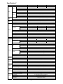
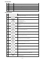
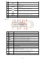
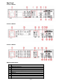
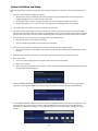
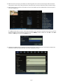
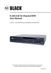
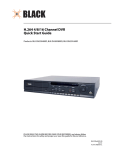
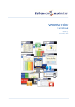
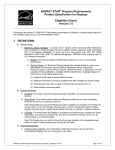
H.264 4/8/16 Channel DVR Quick Start Guide Products: BLK-DH200400DH, BLK-DH200800DH, BLK-DH201600DH PLEASE READ THIS GUIDE BEFORE USING YOUR RECORDER, and always follow the instructions for safety and proper use. Save this guide for future reference. BLK-D20xx00DH_RQ © 2012 DIGIOP, Inc. Specifications* ITEM BLK-DH200400DH Channel Input 4 channel Input level Output Signal format Alarm Yes 1 HDMI 1, up to 1080p BNC 1 1 Input / output 4 channel line input / 1 channel line output Audio CODEC G.711 (ADPCM) Sensor Input 4 channels (NC/NO selectable) Alarm output 1 Alarm out by Sensor, Motion and Video Loss Compression H.264 Resolution Display QUADPLEX (Playback/Record/Network/Backup) D1 120 fps 120 fps 120 fps Half D1 120 fps 240 fps 240 fps CIF 120 fps 240 fps 480 fps Recording quality grade 5 grades Recording mode Continuous / Schedule / Motion/ Sensor/ Manual Motion detection Motion detection setup by grid Recording by channel Yes Pre & post recording Yes, 10 sec. ~ 60 sec. Frame rate ( /sec) 30 fps/channel Multi-secoding Playback 1, 4 Multiple channels 2TB 1 each (2 each without DVD-RW) 1 USB flash drive Video and still image USB external HDD Video and still image Network Video and still image Serial ATA I port for DVD-RW 1 USB port 1 front, 1 back Menu display GUI Input method Remote control, mouse, keyboard (USB) controller Console Serial port – PTZ control 1 RS-485 Termination Yes Dynamic DNS Network Yes (free DDNS) Network interface 10/100BASE-T Ethernet (RJ-45) Network streaming Web viewer (1:1) Network Access Features 4 channels Serial ATA I Capacity of 1 HDD E-SATA port Backup 4 channels Timeline, Event, Archive, Log Internal HDD Storage 1, 4, 8, 16 2x, 4x, 8x, 16x, 32x 4 channels Interface type HDD 1, 4, 8 Single channel Playback speed Search mode User I/F 16 channel VGA Multi-operation Record 8 channel NTSC Spot Audio BLK-DH201600DH Composite, 1.0 Vp-p, 75 Ω Video loss check Video BLK-DH200800DH CIF 120 fps / 100 fps Live, Search, Backup, PTZF Cam Control, Remote Setup 3G mobile viewer (1:1) Live, search, PTZF Single site monitoring system: Live, Search, Backup, PTZF Cam Control, Remote Setup Multi-sites monitoring system Live, Search, Backup, PTZF Cam Control, Remote Setup DLS (Day Light Saving) & NTP Yes Internal Beep By Alarm, Motion, Video Loss, HDD error Multi-Language Yes (more than 13 languages) SW upgrade USB flash drive, network Page 2 ITEM BLK-DH200400DH NTP BLK-DH200800DH BLK-DH201600DH Yes Watermark Power 12 Vdc @ 5 A Operating temperature 41 °F ~ 104 °F (5 °C ~ 40 °C) Storage temperature Weight 14 °F ~ 122 °F (-10 °C ~ 50 °C) Unit weight / gross weight 9.04 lb / 13.67 lb (4.1 kg / 6.2 kg) 15.0” x 13.4” x 2.83” (380 mm x 340 mm x 72 mm) Dimension (w x h x d) *Specifications and exterior design are subject to change without notice. Product Components The package contains the DVR unit and the components shown below. DVR unit Software CD (with user manual) / Quick Start Guide / HDD mounting screws (4) Adaptor (DC 12V 5A) and power cable Mouse Remote control and batteries / HDD mounting brackets (1 set) HDD data power cable (1) Front Panel Page 3 Front Panel LEDs No. Name Description A CH1~16 Indicates that the channel is being recorded. B HDD Indicates that the system is accessing the hard disk. C ALARM Indicates that sensor(s) is/are triggered or motion is detected. D NETWORK Indicates that a network client is connected E BACKUP Indicates that a USB or DVD-RW device contains stored data F POWER Indicating that the system is switched on. Front Panel Buttons No. Name Description 1 Channel keys. For channel 10, press the 0 key. For channel 11, press the +10 and 1 key. For channel 16, press the +10 and 6 key. 2 In playback mode, press to rewind the recording. Press again to increase the rewind speed. 3 Press to select an audio mode: MUTE – Mute all 4 channels. SINGLE - Highlighted channel only. MIX - Mix all 4 channels. 4 Jump/step backward. In playback mode, the playback position moves 60 seconds backward. 5 In playback mode, press to fast forward the recording. Press again to increase the fast forward speed. 6 Press to enable/disable ALARM operation. 7 Jump/step forward. In playback mode, the playback position moves 60 seconds forward. 8 Press to start or stop manual recording. 9 In live display mode, press to open the SEARCH menu. 10 In playback mode, press to play/pause the footage. 11 Press to open the SETUP menu. 12 Enable/disable the automatic sequence of display of channels in full screen, quad, 9-split display mode. 13 Press to control Pan/Tilt/Zoom operations. 14 Press to capture video in jpeg format in live or playback mode. 15 (LEFT) Press to move left or to change the values in Setup mode. It is also used as the number 4 when entering password. Page 4 No. Nam me Description 16 (U UP) Press to mo ove up the menu in Setup mode. It is also used as the number 1 when w entering password. 17 (RIG GHT) Press to mo ove right or to change the values in Setup mode. It I is also used as the number 2 when enttering password. 18 (DO OWN) Press to mo ove down the meenu in Setup mod de. It is also used d as the number 3 when entering paassword. 19 Press to sele ect desired menu u item or to store e the setup value e. 20 Press for tem mporary storagee of the changed value or to returrn to the previous menu screen. To save a sn napshot image or video clip on a USB flash drive, or o upgrade firmw ware with a USB flash drive, first connecct the USB flash drive d to the USB port. p 21 USB port p 22 OPEN/C CLOSE Press to opeen or close the disk tray. 23 DVD drive d To save videeo, insert a CD-R//DVD-R Remote Control No. Name Description n 1 ID When a remo ote control ID number n is set in the DVR, inpu ut the DVR ID number. n 2 C REC To start and stop manual re ecording 3 Number To select chaannel (1, 2, .. 16 6) or to enter DV VR ID number. 4 REW F/R During playb back - To move e the playback position p 60 secconds backward d. During pause - To move the playback possition 1 frame backward. b 5 ADV F/A During playb back - To move e the playback position p 60 secconds forward. During pause - To move the playback possition 1 frame forward. f 6 W REW To rewind th he recording. Prress again to increase the rew wind speed. 7 AY/PAUSE PLA To play or to o pause the foo otage in playback mode. 8 FF To fast forwaard the recording. Press again n to increase th he fast forward speed. 9 ntrol button Con Press to movve the menu ite ems or select channel. 10 TUP SET To open the SETUP menu. 11 ARCH SEA To open the search menu. 12 C ESC During settin ng - To return to t previous menu screen. During playb back - To exit frrom playback System Lockk – To lock a sysstem when pressing ESC button for 5 second ds. System Unlo ock – To unlockk a system when pressing ESC C button for 5 se econds. 13 ACKUP BA To start operrations of backkup in live or plaayback mode. (The same fu unction button as CAPTURE on the front pan nel of DVR) 14 Q SEQ To start auto o sequencing of the screen in full screen mode. (Toggle) Page 5 Re ear Pane el BLK-DH200400D DH DVR DH DVR BLK-DH200800D BLK-DH201600D DH DVR Re ear Panel C Connectorss No. 1 2 3 4 5 6 7 8 9 10 11 Item m Coo oling fan Vid deo input & videeo output Aud dio Input HD DMI video outpu ut RS--232C terminal (For testing pu urposes) VGA A output eSA ATA port Nettwork RS-45 Ethernet port USB B port RS--485 PTZ, senso or input (4), alarm output (1). See user manu ual for more info ormation. DC12V Power Input Page 6 System Installation and Setup Follow the steps below to install and setup your system. For more information, refer to the user manual provided on the CD. 1. Plan your entire installation carefully, considering: Position of the cameras to effectively cover your surveillance targets. Avoid locations and orientations where bright light might shine on or reflect onto the camera lens. Security of the camera and the cabling to the DVR. Is it easy for an intruder to disable the cameras? Location of the DVR. Is it in a secure location? Is the temperature and humidity within specifications? 2. Install your cameras in accordance with the manufacturer’s instructions. 3. Connect the video/audio and power extension cables to the cameras, then route them to the location of the DVR. Note that video extension cables connectors are usually different at each end; the end with the male power connector attaches to the camera drop cable, the end with the female power connector attaches to the power source and DVR. 4. Place the DVR on a clean, flat surface. Do not apply power to the DVR at this time. 5. Plug the USB mouse to the USB port on the DVR. Connect a monitor to the VGA connector on the back of the DVR. Connect the video extension cable from each camera to a video port on the back of your DVR. If the camera location has a microphone, also attach the audio cable to an audio input connector on the back of the DVR. 6. Attach the power extension cable to the cameras to the recommended power source to power them on. 7. Power on the DVR. Connect the power adapter to the DC12V power connector on the back of the DVR. Power on the monitor. Connect the power cable to the power adapter and to a standard 120 VAC outlet. When the DVR is powering on, an initialization window will appear. 8. When the CHOOSE LANGUAGE window opens, use the mouse to open the dropdown list, select the language you prefer to use, then click Next. NOTE: You can also change the language setting later through the SETUP menus. 9. In the DAYLIGHT SAVING window, use the mouse to open the dropdown menus and select the DLS region, date and time. When the correct date and time is shown, click Next. NOTE: The date and time setup in the DVR is used to timestamp recorded video recordings. It is very important that this be set correctly if video recordings are used as evidence. Page 7 10. When the main screen opens, you should see a video image from each camera. Use this image to refine the manual settings of the camera. These settings include the camera direction, and may include focus, zoom, and other settings. 11. Right click the mouse anywhere on the DVR screen then click SETUP, or press the SETUP button on the front panel to access the SETUP menu. If a LOGIN window opens, click the virtual keyboard button (at the right of the password entry field) to open the keyboard window. Use the keyboard to click in the default ADMIN password, “1111”, then click OK. In the LOGIN window, click OK again to open the DVR SETUP menus. 12. Configure the SETUP menus to customize the DVR settings for your system. Refer to the user manual included on the CD for more information about DVR Setup and system configuration settings. Page 8 Network Connections LAN Connection – Using a crossover cable without a switching hub Connect to the system directly using a crossover type network cable. LAN Connection – Using a switching hub Connect to the system using a hub (switching hub) and an Ethernet cable (10BASE-T/100BASE-TX CAT 5 LAN cable). Internet (ADSL) Connection Connect to the system using a router or ADSL modem and an Ethernet cable (10BASE-T/100BASE-TX CAT 5 LAN cable). Smartphone Access When your DVR is configured for access across the Internet, you can remotely monitor and control you video security using the free smartphone app Blackhawk. This app features: View from 1 to 16 cameras View images in portrait or landscape (single channel) Monitor multiple locations 3G/Wi-Fi compatible For more information, and to download and install the app, go to: ® ® ® ® Apple iPhone , iPod touch , or iPad : http://itunes.apple.com/app/blackhawk-for-iphone/id422091119? Android™ phones: http://www.androidzoom.com/android_applications/tools/blackhawk_tlcv.html Page 9