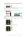
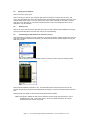
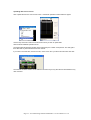
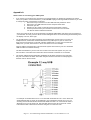
1
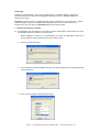
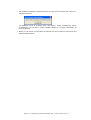
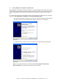
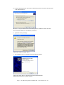
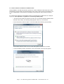
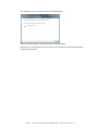
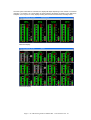
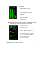
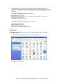
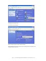
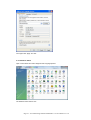
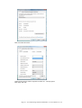
Trantec S5.5 Monitoring
Software Manual
Initial Setup
Minimum PC Requirements 1.6 GHz CPU, 256 MB Memory, 1 available USB port, Windows XP
Recommended PC >2.0 GHz CPU, 512 MB (XP) 1 GB (Vista) memory, 2 available USB2 ports,
Windows XP or Vista.
Important: If you are using a non-English language version of Windows you must select the ‘.’ decimal
number separator symbol in the ‘Regional and Language Option’ section of Control Panel. For
instructions on how to do this go to Appendix B at the end of this document.
1. Installing the monitoring software
1.1 The installation files are located in the ‘Trantec S5 Series Install’ folder on the Trantec CD. There
are three files: Setup.exe, SETUP.LST and S5.CAB.
i.
Before installing the software it is recommended you close any applications that may be
running. Start the setup by double clicking on the Setup.exe file.
ii. Click OK from the first dialog.
iii. Do not change the default installation directory and click the large button in the upper left-hand
side of the window.
iv. Click ‘Continue’ Using the default Program Group
Page 1 – S5.5 Monitoring Software Manual Rev 1.2 for Software Ver 1.0
v.
The installation should then unpack all the files and copy them to the hard drive. Click OK to
complete the process.
The application can be run by clicking ‘Start’, ‘All Programs’, ‘Trantec S5 Monitoring’, Trantec
S5 Monitoring. You may wish to create a desktop shortcut to C:\Program Files\Trantec S5
Monitoring\S5.exe.
vi. Before you can monitor your S5 series microphones you must connect the USB system and
install the hardware driver.
Page 2 – S5.5 Monitoring Software Manual Rev 1.2 for Software Ver 1.0
2.1
Trantec USB driver installation for Windows XP
During installation, the USB driver files are copied to the ‘Trantec USB Driver’ folder within the ‘Trantec
S5 Monitoring’ program folder. For the USB system to work, every Trantec receiver must appear to your
PC as a unique device. For this reason it is necessary to load a driver for every receiver you wish to
use.
If you will be using more than one S5 Series receiver you should connect a USB 2.0 hub to a USB port
on your PC. (See ‘Appendix A’ for guidance on connecting a USB system).
i. Connect your first Trantec S5 receiver to the hub. The ‘Found New Hardware Wizard’ should
start after a short delay. If the following dialog appears, select ‘No, not at this time.’
Click ‘Next’.
ii. For the first receiver, select the option "Install from a list or specific location (Advanced)".
Click 'Next'.
Note: For any further S5 receivers you should select “Install software automatically
(Recommended)’ then click ‘Next’ and proceed as from ‘iv’ below.
Page 3 – S5.5 Monitoring Software Manual Rev 1.2 for Software Ver 1.0
iii. From the following window, click the box "Include this location in the search" and then click
on the 'Browse' button.
Browse to ‘C:\Program Files\Trantec S5 Monitoring\Trantec USB driver’ folder. Click ‘OK’.
The correct driver location is now selected, click "Next".
iv. Ignore the warning message.
Click on the 'Continue Anyway' button.
v. The Installation will now complete showing the following Window.
Click on the 'Finish' button to close the Found New Hardware Wizard.
Repeat this sequence for any other receivers.
Page 4 – S5.5 Monitoring Software Manual Rev 1.2 for Software Ver 1.0
2.2 Trantec USB driver installation for Windows Vista
During installation, the USB driver files are copied to the ‘Trantec USB Driver’ folder within the ‘Trantec
S5 Monitoring’ program folder. For the USB system to work, every Trantec receiver must appear to your
PC as a unique device. For this reason it is necessary to load a driver for every receiver you wish to
use.
If you will be using more than one S5 Series receiver you should connect a USB 2.0 hub to a USB port
on your PC. (See ‘Appendix A’ for guidance on connecting a USB system).
i. Connect your first Trantec S5 receiver to the hub. The ‘Found New Hardware Wizard’ should
start after a short delay. If the following dialog appears, select ‘No, not at this time.’
For the first receiver, select the option "Locate and install driver software (recommended)".
Click Continue when the ‘User Account Control’ Dialog asks for permission to continue.
ii. From the following window, click the box "I don’t have the disc. Show me other options."
Page 5 – S5.5 Monitoring Software Manual Rev 1.2 for Software Ver 1.0
iii. Click ‘Browse my computer for driver software (advanced)’
Click Browse then use the dialog box to find ‘C:\Program Files\Trantec S5 Monitoring\Trantec
USB Driver’ folder. Click ‘OK’.
The correct driver location is now selected, click "Next".
iv. Ignore the warning message. Click on the 'Install this driver software anyway' button
.
Page 6 – S5.5 Monitoring Software Manual Rev 1.2 for Software Ver 1.0
The Installation will now complete showing the following Window.
Click on the 'Close' button to close the Found New Hardware Wizard.
Whenever you connect Trantec S5 receivers from now on the driver should install automatically
requiring no further input.
Page 7 – S5.5 Monitoring Software Manual Rev 1.2 for Software Ver 1.0
3.
Basic operation. (Windows XP and Vista forms have a slightly different appearance)
It is important that you read ‘Appendix A - General notes on connecting your USB system’. This will
help to avoid any issues you may find when starting to monitor your S5 series system.
When the application starts, the PC will check the USB sub-system to discover any S5 series receivers.
If no Trantec USB hardware is detected then a warning window is presented.
If USB hardware is detected, the PC first checks the USB connection type then reads and confirms
receiver parameters from each device. This information is displayed in a window as below.
The default setting after installation is for the PC not to load a frequency file into the system but to
display the receiver front panel information. In this mode the hardware is only updated via the right click
panel. See below.
If ‘Load file on Start’ has been selected under the ‘File’ menu, the file for the last set of frequencies used
is opened and compared to the data read from the receivers. If the data matches, then the system is
configured for this file. If the receiver and file data do not match, then you are asked if you would like to
load the file data anyway. A countdown timer will allow 10 seconds for the operator to confirm a file load.
If the countdown expires then the system starts using the receiver hardware data. This situation may
arise when a PC is moved and connected to a different set of receivers. By default the system will not
load the file but present the receiver data.
Page 8 – S5.5 Monitoring Software Manual Rev 1.2 for Software Ver 1.0
Once the system information is confirmed, the display will adjust depending on the number of connected
receivers. If a receiver is in a muted state, the panel graphics will appear as shades of grey. Below are
examples of a 4-way and a 12-way display showing two receivers that have been manually muted.
4 Receiver Display
12 Receiver Display
Page 9 – S5.5 Monitoring Software Manual Rev 1.2 for Software Ver 1.0
Below is a view of a single receiver panel from an 8-way display.
The panels indicate:
i.
The RF signal level for both A and B
diversity channels. The bars are scaled
in micro-volts. A single red bar element
indicates the current mute level.
ii.
The audio VU level scaled in decibels
iii. Diversity LEDs labelled A and B indicating the
current receiver channel.
iv. The battery level.
When approximately one hour of life remains,
the indicator flashes red.
v. The name associated with the
performer/receiver.
vi. The operating frequency.
If you wish to change any of the parameters for a receiver, right click on the receiver panel in the main
display and a receiver detail panel will appear as below.
Note: Changes are only saved to file if either, the system is set to load a file at application start or
a file has been explicitly loaded in to the system using the ‘File’, ‘Load’ menu.
i.
Top line shows the file name.
ii.
An actor or performer name can be entered into
the box on the next line.
iii.
The box on the next line allows the frequency to
be set.
iv.
Moving the slider sets the Mute level from 1 to 10.
The current Mute level is indicated by red markers
on the RF bar graphs.
v.
Clicking ‘User Mute’ will toggle audio mute On/Off
for output from the selected receiver. The Mute
icon will be displayed in the output panel. as in the
12-way display above.
vi.
Clicking OK saves the data to file.
vii.
Cancel returns without saving.
viii.
The receiver band is shown at the bottom.
Should you use the receiver front panel to change the mute level or the tuned frequency, the PC display
will update but this change will NOT be saved to a file. If you wish to change the receiver frequency and
save the change to file, use the detail window as above.
Page 10 – S5.5 Monitoring Software Manual Rev 1.2 for Software Ver 1.0
4. Working with files
Each time the application starts, a ‘Default’ frequency file is generated which contains a set of data that
lies within the frequency ‘Band’ of your receiver. This file can be copied, renamed and edited to your
own requirements see section 4.4 below.
Note: You cannot edit the ‘Default.frq’ file directly so that it is always there for reference. Simply
copy, rename and edit the file.
The S5 file functions work with the same " *.frq " files that are used in the Trantec S6000 professional
series. The frequency file contains the name, the frequency and the mute level for each performer.
Your files must only contain frequencies within the band for your receivers.
4.1
Loading a frequency file into the system
From the File menu click 'Load'
Choose the file you wish to load from the file dialog by either double-clicking on the file name or singleclicking and clicking on ‘OK’. A single frequency will be transferred into the custom frequency location of
each receiver in your system. Receiver one will be allocated the first frequency in the file, receiver two,
frequency two and so on.
Note: The data in the custom bank will NOT be changed when you load a file into the system. Only
the single custom frequency is updated in each receiver.
4.2
Creating a new file
Note: Receiver monitoring will stop during file editing operations
From the File menu click 'New'. Enter a file name and click OK. If you use an existing file name the file
will be immediately overwritten.
When editing, you are always working with the data currently displayed in the editing boxes at the top of
the window.
The data grid and the data entry boxes will be initialised to a temporary value. The left-hand box cannot
be edited, it is purely an indicator of the current data row.
In the second box, you can add any performer name up to a maximum of six characters.
Add the frequency data to the third box. This box will auto complete if possible. For example, entering
83 will result in a frequency of 830.000 MHz, 855 becomes 855.000 MHz and 83525 will become
835.250 MHz. Any frequency is rounded to the nearest 25 KHz grid position, 846.123 would become
846.125 MHz for example.
A mute level should be entered into the fourth data box. Valid values are between 1 and 10. The default
value for this parameter is 5. If the box is left empty a value of 5 is used.
Page 11 – S5.5 Monitoring Software Manual Rev 1.2 for Software Ver 1.0
When all the parameters have been entered click the 'Add' button. This data is then added to a grid
below and the parameter boxes are cleared for your next set of user parameters. This data is
immediately saved to your file.
Repeat the previous steps until you have entered the entire frequency set. Once you have entered all
the data then simply click the ‘Finish’ button or close the file editing window.
4.3
Editing an existing file
Load a file into the data grid by clicking ‘File’, ’Edit’ and choose the file you wish to edit.
When any row of the data grid is selected with the mouse the user data is copied to the editing boxes.
Change the data in these boxes then click the 'Update' button, the selected row of the data grid is
changed.
If you click the 'Insert' button, the currently selected data row is moved down and the editing box data
replaces the row data.
If you click the 'Delete' button, the currently selected data row is removed.
Page 12 – S5.5 Monitoring Software Manual Rev 1.2 for Software Ver 1.0
4.4
Copying an existing file
Click on the 'File', 'Open' menu.
Click on the file you wish to copy using the right hand mouse button. From the Pop-up menu, click
'Copy'. Now right hand click on the area where the files are listed and select 'Paste' from the menu. The
new file will be called "Copy of nnnn.frq" where 'nnnn' is the name of the file you selected. If you then
right click on this filename you can choose 'Rename' from the menu and change the name. Do not
change the ‘.frq’ file extension.
4.5
Deleting a file
Click on the 'File', 'Edit' menu then right click on the file you wish to delete. Select 'Delete' from the popup menu and the file will be removed. Click ‘Cancel’ to close the dialog.
4.6
Transferring file data between the PC and a receiver
Open the frequency data file you wish to transfer to a receiver by clicking “Download file to Rx” from the
‘File’ menu and select the file from the dialog. The file operations window will then appear showing the
data from your file.
Use the drop down list to select the receiver to which you wish to send the frequency data.
Click the button labelled "Send data to Rx". The Status label in the bottom left hand corner of the
window will indicate if the transfer was attempted by showing the number of user parameters that were
sent.
During transfer, the display on the receiver should flash and then update.
Note: File transfer, updates the User custom bank and not the Single custom frequency, this is
updated from the ‘File’, ‘Load’ menu option. The custom bank frequencies can only be
accessed from the receiver front panel.
Page 13 – S5.5 Monitoring Software Manual Rev 1.2 for Software Ver 1.0
Uploading data from a receiver
Click “Upload file from Rx” from the ‘File’ menu. A blank file operations window will then appear.
Use the drop down list to select the receiver from which you wish to upload data.
Click the button labelled "Upload from Rx".
The Status label should read "Number in Set" followed by the number of frequencies. The data grid is
then filled with any data transferred from the receiver.
If you wish to save this data, click on the 'File', 'Save' menu. Give your file a name and then click 'OK'.
Once the file has been saved it can be edited in the same way as any other file and downloaded to any
other receivers
Page 14 – S5.5 Monitoring Software Manual Rev 1.2 for Software Ver 1.0
Appendix A
General notes on connecting your USB system
•
If you connect your receivers one at a time as you load the drivers you should not experience any issues.
Once your system is connected however, you should NOT unplug or rearrange USB connections. If you need
to change the order of connections you should:
1. Disconnect all your receivers from the USB hubs and power them down.
2. Disconnect your USB hubs from the PC and power them down.
3. Shut down your PC.
4. Restart your PC, power up the hubs and reconnect them to the PC.
5. Power up and reconnect your receivers one at a time in the new order.
You will not need to load drivers this time.
Once your system is set up we recommend that you label the USB cables close to the type B connector on
your receivers. This way you know which receiver will appear where on the monitoring screen bearing mind
the display is in rows, left to right.
•
You should imagine your USB connections as a tree branching out from ports on your PC. For
multiple devices, a USB 2 hub should be attached to any USB 2 port on your PC. If the hub
does not have enough ports you should ‘cascade’ multiple hubs. You may use more than one
USB port on your PC, connect Hub1 to Port I and Hub 2 to Port 2 for example.
Only use USB 2 ‘Hi Speed’ hubs. This ensures the system will connect to your PC’s enhanced
USB controller for maximum efficiency.
The first hub attached to your PC acts as a root hub to the rest of the system. A 4 port ‘root’
hub can take 4 connections from other hubs. We recommend a maximum of 12 receivers.
•
The Trantec USB monitoring application will display the S5 series receivers in the order that
they are connected to the hubs. The further away the receiver is from the PC USB port(s) the
later the order on the PC screen.
For example: An S5 attached to Port 1 on a Hub which is attached to Port 1 on the ‘Root’ hub
will be displayed first on screen an S5 attached to port 2 will appear second an so on. If you
are using 4 Port hubs then another S5 would be attached to Port 1 on a second hub which is
attached to Port 2 on the ‘Root’ hub. We could then attach 3 more S5’s to this hub. A third
hub would be used to attach more receivers using Port 3 on the ‘Root’ hub.
Page 15 – S5.5 Monitoring Software Manual Rev 1.2 for Software Ver 1.0
•
On some USB 2 hubs, the ports are not physically numbered in the same order as the
connection to the USB system as a whole. This can lead to an unexpected display output. For
example: on a D-Link DUB-H7 hub the port numbered 1 is actually connected to Port 5 on the
USB system.
The following Hubs ARE connected in correct order.
Belkin F5U237 Seven port hub.
(Physically stackable and provides a very compact 12 way connection from two hubs)
D-Link DUB-H4 Four port hub.
HP DG954A compact Four port hub
The following Hubs we know are NOT connected in order.
D-Link DUB-H7 Seven port hub
Maplin A38BG Seven port hub
Targus PAUH212 Seven port hub
Trust Easy connect HU-5770 Seven port hub
Appendix B
Selecting a decimal number separator for a non-English language version of Windows.
1. For Windows XP
Open Control Panel and select ‘Regional and Language Options’
The Windows XP ‘Classic’ view
Page 16 – S5.5 Monitoring Software Manual Rev 1.2 for Software Ver 1.0
The Windows XP ‘Category’ view
The following window will appear
Select ‘Change the format of numbers, dates, and times’.
From the Classic view, or from the window above, the following window will appear (In this
example the region is Germany).
Page 17 – S5.5 Monitoring Software Manual Rev 1.2 for Software Ver 1.0
Click ‘Customize’.
Under ‘Decimal symbol’ use the dropdown to select the ‘.’ full stop symbol.
Click ‘Apply’ then ‘OK’.
Page 18 – S5.5 Monitoring Software Manual Rev 1.2 for Software Ver 1.0
Once again click ‘Apply’ and ‘OK’.
2. For Windows VISTA
Open ‘Control Panel’ and select ‘Regional and Language Options’.
The Windows Vista ‘Classic’ view
Page 19 – S5.5 Monitoring Software Manual Rev 1.2 for Software Ver 1.0
The Windows VISTA ‘Control Panel Home’, choose ‘Clock, Language, and Region’.
The following window will appear.
Select ‘Change the date, time, or number format’.
From the Classic view, or from the window above, the following window will appear (In this
example the region is Germany).
Page 20 – S5.5 Monitoring Software Manual Rev 1.2 for Software Ver 1.0
Click ‘Customise this format…’
Under ‘Decimal symbol’ use the dropdown to select the ‘.’ full stop symbol.
Click ‘Apply’ then ‘OK’.
Page 21 – S5.5 Monitoring Software Manual Rev 1.2 for Software Ver 1.0
Once again click ‘Apply’ and ‘OK’.
Page 22 – S5.5 Monitoring Software Manual Rev 1.2 for Software Ver 1.0