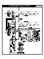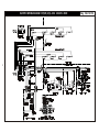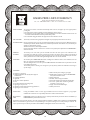
1
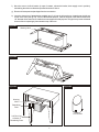
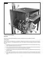
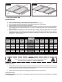
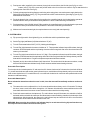
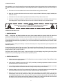
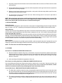
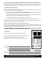
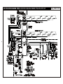
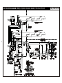
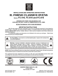
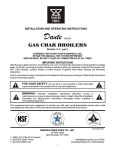
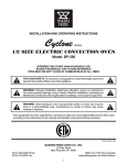
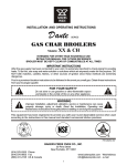
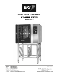
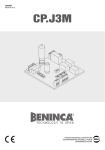
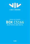
INSTALLATION AND OPERATING INSTRUCTIONS
FLOOR MODEL
ELECTRIC DECK OVENS
INTENDED FOR OTHER THAN HOUSEHOLD USE
Models:
EP, EB, ER
RETAIN THIS MANUAL FOR FUTURE REFERENCE
OVEN MUST BE KEPT CLEAR OF COMBUSTIBLES AT ALL TIMES
FOR YOUR SAFETY: Do not store or use gasoline or other flammable vapors and
liquids in the vicinity of this or any other appliance.
!
!
!
WARNING: Improper installation, adjustment, alteration, service or maintenance
can cause property damage, injury or death. Read the Installation, Operating and
Maintenance Instructions thoroughly before installing or servicing this equipment.
!
!
WARNING: Initial heating of oven may generate smoke or fumes and must be
done in a well-ventilated area. Overexposure to smoke or fumes may cause
nausea or dizziness.
!
Note: Only Pizza or Bread can have direct contact with ceramic decks. All other food products must be
placed in a pan or container to avoid direct contact with ceramic decks.
This equipment has been engineered to provide you with year round dependable service when used
according to the instructions in this manual and standard commercial kitchen practices.
C
UL
R
US
LISTED
COMMERCIAL ELECTRIC
COOKING APPLIANCE
ANSI/NSF 4
BAKERS PRIDE OVEN CO., INC.
P/N U4190A 9/07
30 Pine Street
New Rochelle, NY 10801
(914) 576-0200 Phone
(914) 576-0605 Fax
(800) 431-2745 US & Canada
www.bakerspride.com Web Address
1
INDEX
INSTALLATION INSTRUCTIONS
SECTION
ITEM
PAGE
1
Receiving
3
2
Location and Minimum Clearances
3
3
Installation
3
4
Stacking
5
5
Steam Option
5
6
Installation of Decks
6
7
Electrical Connection
7
8
System Check
8
9
Initial Start-Up
9
OPERATING INSTRUCTIONS
SECTION
ITEM
PAGE
1
General Baking
9
2
General Baking Tips
9
3
Special Features
10
4
Cleaning
10
5
Service and Trouble Shooting
11
6
Rating Plate
11
7
Wiring Diagrams
8
Warranty
Attachment:
12-15
16
Parts List EP, EB & ER Series, Large Electric Deck Ovens
2
INSTALLATION INSTRUCTIONS
MODELS COVERED
MODEL
EP1(2,3)-8-3836
EP1(2,3)-8-5736
EB1(2,3)-8-3836
EB1(2,3)-8-5736
ER1(2,3)-12-3836
ER1(2,3)-12-5736
NUMBER OF ELEMENTS
TOTAL KW
8 elements per Deck
12 elements per Deck
8 elements per Deck
12 elements per Deck
8 elements per Deck
12 elements per Deck
8 kw per Deck
12 kw per Deck
8 kw per Deck
12 kw per Deck
8 kw per Deck
12 kw per Deck
PHASE
1 or 3 phase
1 or 3 phase
1 or 3 phase
1 or 3 phase
1 or 3 phase
1 or 3 phase
1. RECEIVING
Read the notice on the outside carton regarding damage in transit. “CONCEALED DAMAGE”, damage discovered
after opening the crate(s), must be reported immediately to the carrier. The carrier will perform an inspection of the
damage and furnish forms for the consignee's claim against the carrier. Retain all packing material - including outer
carton until the inspection has been completed.
2. LOCATION AND MINIMUM CLEARANCES
Adequate air space must be provided for proper venting of the controls and provisions must be made for venting of the
cooking vapors. The Oven must be installed in a well-ventilated area and following minimum clearances must be
maintained at all times:
Ovens can be installed with “Zero” clearances (back and sides) from combustible and non-combustible materials.
The Ovens may be installed on combustible Flooring if mounted on the Legs provided. Keep the area around your
oven free and clear of all combustible materials.
3. INSTALLATION
Place the oven and parts as close to the area of final installation before uncrating. Your oven is packed sitting on its
back. Leave it on its back while unpacking. The pallet may be left under the oven for convenience in further handling.
Unpack carefully to avoid damage to the oven. If concealed damage is discovered, follow the instructions detailed in
section 1 above.
a) Legs are shipped in a separate carton complete with mounting bolts and washers. Firmly bolt two legs (in case
of casters, the two with the brakes must be used here) to the upper two corners (front) of the oven as it rests on
the pallet. Note: (See fig. # 1).
b) Using sufficient help, tilt the oven forward and lower it down so that the two front legs come to rest on the floor.
(See fig. 2)
WARNING: In case of casters, the brakes must be firmly applied and in a locked position before proceeding
with the next step, in order to prevent the oven from rolling away while lifting the back. It is advisable to have a
person in front of each caster leg, bracing his foot firmly against the casters.
c) Using proper lifting equipment, raise the back of the oven to a height slightly more than the height of the legs,
remove the pallet and the rest of the packing material and place a sturdy support under the back side. (See fig.
#3)
d) Mount the two back legs and firmly tighten the bolts, then lift the back of the oven somewhat and remove the
support.
e) Provide a suitable restraining chain or cable to securely tether the appliance to the building structure. The
restraining chain or cable should be of such length that it will stop movement of the appliance BEFORE there is
any strain on the power supply cable.
3
f)
Move the oven to its final location (in case of casters, release the brakes, then reapply once in position),
maintaining the minimum distances specified in section 2. Above.
g) Remove all loose parts and packages from the oven interior.
h) Insert the short piece of tapered pipe supplied (see fig. 4) into the hole at the top, located near the left rear
corner of the oven (see fig. 5A). Turn it to the desired direction, mark the location of the holes and drill three
1/8” diameter holes, then secure it with the screws supplied for that purpose. This pipe is to prevent accidental
closure of the vent opening by items stored on top of the oven.
Figure #1
Warning Label
Figure #2
Figure #4
Figure #3
Warning
Label
BA
K
ER
S
PR
IDE
Restraining
Plate
Flue Diverter
Left Rear Leg
w/Caster &
Restraining Plate
4
4. STACKING
These ovens can be stacked up to three high. Each unit is built exactly the same, so it does not matter in what order
they are stacked. However, in case of a mix of 8” and 12” deck heights, it is advisable to place the higher deck(s) on the
top, e.g.: mount the legs to one of the lower decks.
Once the unit with the legs is in place (in case of casters make sure the brakes are on), with the proper lifting equipment
gently place the next oven on top of the first one and line up the back and sides with each other. (If the ovens came with
Steam Option, read section 5. below before proceeding). Once the two ovens are properly stacked, install the stacking
brackets as per instructions supplied with the kit. In case of a third unit, gently place the oven on top of the second one,
line up the back and sides, then connect to the stacking brackets.
5. STEAM OPTION
If this option has been ordered and supplied, remove the control panel(s) and left access cover(s) to gain access to the
steam plumbing as follows:
a) Remove all screws and vent knob from the control panel. Loosen the set screw on the thermostat knob and
remove it. Pull the control panel out at the bottom, then down and out from the vent rod. Slip the right flange
hole of the control panel back onto the vent rod, then replace the vent knob to keep the control panel in an
open and secure position. (See fig. 5l)
b) Remove all screws from the left access panel, then pull it forward and out of the oven.
c) After the internal pipe connections have been completed as per instructions below, follow the instructions
supplied by the manufacturer of the steam generator and the manufacturer of the steam trap for final hook up
to the steam supply.
Stacked ovens
a) In all but the top oven, punch four 1 1/2” diameter holes in each of the top covers, utilizing the 1/8 locating
holes. (See fig. 5b)
b)
Loosen the upper pipe union(s) and remove the upper part(s) from all but the top oven. (See fig. 5c).
c) Raise the left side of the upper unit and place a piece of wood or similar material to keep a 1” to 1 1/2” space
between the two ovens.
d) Insert the connecting pipe, small end up, (see fig. 5d) through the access opening of the lower unit and screw it
into the lower pipe union of the upper oven, leaving a space between the lower union sections identical to the
space between the two ovens.
e) Lift the upper unit, remove the spacer and carefully lower it until the two union parts in the lower oven meet.
Adjust the height of the connecting pipe, if necessary, to have a perfect match at the lower union, then tighten
the lower union.
WARNING: It is very important to have a good match at the lower union before tightening it. If the connecting
pipe is too long or too short, this will put undue stress on the pipe joints and could cause failure of these
components and property damage or injuries as well.
f)
At the end, insert the connecting pipe, small end up, through the appropriate opening at the base of the bottom
unit and screw it into the lower pipe union.
Single Oven
Insert the connecting pipe, small end up, through the appropriate opening of the base and screw it into the lower pipe
union. (See fig. 5e)
5
Figure #5
a
b
f
h
c
g
e
d
j
k
i
l
6. INSTALLATION OF DECKS
Steel Decks
Steel Decks for Bake and Roast Application are factory installed and no further installation is required.
Ceramic Decks
Ceramic Decks for Pizza Application are shipped in a separate carton. Depending on the model, two (see fig. 6a) or
three slabs (see fig 7a) are provided with each oven. This material is heavy and fragile and should be handled
carefully.
a) Depending on the model, three or four deck supports (metal channels) have to be inserted in the oven, front to
back, flanges down and flat side up. (See fig. 5f).
b) Slide one slab into the bake chamber along the deck supports on the left side, lower the front end carefully to
avoid chipping of the deck corners, then push tightly against the left oven wall.
c) Repeat the above for the second (and third) slab, pushing it as tightly as possible against the previous one to
prevent any gaps.
d) With a long hook or similar tool, reach in and pull all of the slabs as far to the front as possible. Insert one (or
two) of the wedges in the back and one at the right side of the oven (see figs. 6b & 7b) and tap them down
lightly.
6
Figure #6
Figure #7
6b
7b
7a
6a
7. ELECTRICAL CONNECTION
General Instructions
a)
b)
c)
d)
e)
f)
Only a licensed electrician should make the electrical connections.
Make sure electrical supply corresponds with that specified on the rating plate.
Only use copper conductors rated at 90°C suitably sized for the electric current drawn.
All pole disconnect(s) must be provided by the installer.
When installed, unit must be electrically grounded in accordance with the local codes and/or the latest edition
of the National Electrical Code ANSI/NFPA No. 70 in USA or Canadian Electrical Code, CSA Standard C22.1,
Part 1 in Canada.
FOR CE UNITS: The appliance must be connected by an earthing cable to all other units in the complete
installation and thence to an independent earth connection in compliance with EN 60335-1 and/or local codes.
If flexible line cordage is used to connect the equipment, it should be a minimum of H07RN-F type conforming
to EN60335-1 and/or local codes.
E(PBR) - 3836 - 8(12) Power and Current per Deck Power Supply E(PBR) - 5736 - 8(12) Power and Current per Deck
KW
L1 (amp) L3 (amp) L2 (amp) N (amp) Volts (Phase)
KW
L1 (amp) L3 (amp) L2 (amp) N (amp)
8.0
38.6
38.6
208 (1)
12.0
57.8
57.8
8.0
21.0
25.0
21.0
208 (3)
12.0
33.5
33.3
33.5
7.3 - 8.7 33.3 - 36.3
33.3 - 36.3
220-240 (1) 11.0 - 13.0 50.0 - 54.6
50.0 - 54.6
7.3 - 8.7 18.0 - 19.7 21.5 - 23.5 18.0 - 19.7
220-240 (3) 11.0 - 13.0 29.0 - 31.6 28.9 - 31.5 29.0 - 31.6
7.3 - 8.7 16.7 - 18.2
16.7 - 18.2
440-480 (1) 11.0 - 13.0 25.0 - 27.3
25.0 - 27.3
7.3 - 8.7 9.0 - 10.0 10.8 - 11.8 9.0 - 10.0
440-480 (3) 11.0 - 13.0 14.5 - 15.8 14.4 - 15.7 14.5 - 15.8
8.0
35.0
35.0
400-Y (1)
12.0
52.3
52.3
8.0
8.8
13.0
13.0
4.2
400-Y (3)
12.0
17.5
17.4
17.4
0.1
NOTE: EACH OVEN REQUIRES A SEPARATE CONNECTION !
!
CAUTION
Overexposure to smoke or fumes may cause nausea and dizziness.
Be sure the oven is placed in a well ventilated area.
!
Field Connections
a) Remove all screws and vent knob from the control panel(s). Pull control panel out at the bottom, then down and
out from the vent rod. Slip the right flange hole of the control panel back onto the vent rod, then replace the vent
knob to keep the control panel in an open and secure position.
b) Remove all screws from the left access panel(s), then pull forward and out of the oven.
Stacked ovens only!
In all but the top oven, punch four 1 1/2” diameter holes in each of the top covers, utilizing the 1/8 locating
holes. (See fig. 5b)
7
c)
Feed power cable (supplied by the customer) through the access hole at the left side (see fig 5g) or at the
bottom (see fig. 5h) of the oven and pull the cable to the front of the oven where it may be attached to the
opening in the oven frame. See fig. 5i).
d) Following the appropriate wiring diagram conforming to the rating plate, connect the power supply leads to the
field wiring terminal block (see fig. 5j). The ground wire should be connected to the grounding lug (see fig. 5k)
attached to the oven frame.
e) For single phase 2-wire or three phase 3-wire supplies, the controlling branch circuit is designed to operate at
208-240 volts AC and is pre-wired at the factory between L1 and L2 of the field wiring terminal block.
f)
For three phase 4-wire 230/400 Volts AC 50hz supplies, the controlling branch circuit is designed to operate at
230 volts AC and is pre-wired at the factory between L1 and N of the field wiring terminal block.
g) Make sure all connections are tight, then replace the access cover(s) and control panel(s).
8. SYSTEM CHECK
a) Flip up oven light switch. Oven lights will go on, and off as the switch is pushed down again.
b) Set the Top (right) and Bottom (left) Heat switches to “O” (off).
c)
Turn the Thermostat knob to 300°F (150°C). Nothing should happen.
d) Turn the Top (right) heat switch counter-clockwise to “5” . The top amber indicator lamp will illuminate, the right
contactor will be activated and the top heating elements will be energized. After some time these items will
start to cycle on and off.
e) Turn the Top (right) heat switch clock wise to “10” (high). The top amber indicator lamp will illuminate, the right
contactor will be activated and the top heating elements will be energized and all should stay that way until the
heat switch is turned back to “0” again or the preset temperature has been reached.
f)
Repeat d) and e) above with the Bottom (left) Heat switch. The results should be the same as above, except
this time it will be the bottom indicator lamp, the left contactor and the bottom heating elements.
Ovens with Timer Option
Turn the timer knob clockwise past the “0” and set a time of 2 minutes. At the end of 2 minutes, the timer knob will be at
“0”, you will hear the buzzer and see the green indicator lamp on, and all three will stay that way until you turn the timer
knob counter-clockwise to “O” to switch them off, or turn the knob clockwise for more time and repeat the above with
the same or a different setting.
Ovens with Steam Option
Never activate the steam timer when the oven is cold, since the steam will immediately condense and turn to
water.
a) The steam timer can be adjusted from 1 to 60 seconds and has been factory set for 3-5 seconds. To change
this time, insert a small screw driver through the 1/4” diameter hole below the steam switches and turn the
timer shaft clockwise to increase or counter-clockwise to decrease this time delay setting.
b) Press both steam switches simultaneously. The red indicator lamp will illuminate, the solenoid coil will be
activated and the solenoid valve will open and allow steam to enter the baking chamber for the duration of the
selected time. After that period, the power to the red indicator lamp and solenoid coil will be cut off and the
solenoid valve will shut down the flow of steam to the oven.
WARNING: Never open the door while the red indicator lamp is on and steam is being injected into the oven,
since exposure to live steam can cause serious injuries.
8
9. INITIAL START-UP
After installation, your oven will need a few hours to evaporate the moisture in the deck and in the insulation and to burn
off the thin coat of oil on the sheet metal parts. The following steps must be completed before your new oven is ready for
use:
a) Place the oven in a well ventilated area in order to deal with the ensuing smoke and smell.
b) Open the oven door and make sure the oven cavity is empty and that the decks are properly installed (see
section 6. above).
c) Close the oven door and set the temperature knob to 300°F (150°C) for about an hour or so.
d) After that, increase the temperature to 500°F (260°C) for at least another hour or until all the smoke and fumes
have disappeared. This procedure will remove most of the moisture and help insure good bake results.
!
CAUTION
Overexposure to smoke or fumes may cause nausea and dizziness.
Be sure the oven is placed in a well ventilated area.
!
OPERATING INSTRUCTIONS
1. GENERAL BAKING
NOTE: Only Pizza and Bread products can have direct contact with the Ceramic Deck. All other food
products must be placed in a metal pan or porcelain dish to avoid direct contact with the ceramic deck.
Pizza can be baked on the deck, on a screen or in a pan. When you determine the combination of method, ingredients
and temperature that results in the right bake for your crust, sauce and cheese combination and your customer's taste,
mark and keep it.
Deck baking refers to baking Pizza directly on the deck. Generally it is a thin product that requires temperature of at
least 550°F (290°C).
Screen baking refers to baking Pizza on a screen. The screen lifts the Pizza off the deck. The screen may be removed
near the end of the bake time to give the bottom of the Pizza a crispier crust and a darker color. Bake temperatures
range from 500°F (260°C) to 550°F (290°C).
Pan baking refers to baking Pizza in pans. Crusts can be thick or thin and toppings range from light to heavy. Bake
temperatures for pan baking range from 450°F (235°C) to 500°F (260°C).
2. GENERAL BAKING TIPS
a) At day's end, turn the thermostat to the “O” (off) position to conserve energy, leaving the Top and Bottom Heat
controls set for next day's operation.
b) In the morning, preheat for one hour at 50°F (30°C) lower than your baking temperature with the vent closed
(pushed all the way in) for a faster recovery.
c) 15 to 20 minutes before loading the oven, raise the thermostat setting to your baking temperature and make
sure the Top and Bottom Heat switches are set correctly for the product you intend to bake.
d) Check the bottom color of the Pie and reduce the Top Heat once you notice the bottoms to get very light. This
will make the bottom elements come on more often, helping to maintain the desired color.
e) When the oven has not been used for a while, there is a tendency for the bake deck to get very hot.
Consequently, when it is slow and the oven idling, set the thermostat at least 50°F (30°C) lower than your
normal baking temperature. Then, when you put in a pizza, increase the thermostat to the normal setting,
providing the quick extra top heat required to balance the bottom heat. At the end of the bake, the thermostat
should then be turned down to the lower setting before the deck gets too hot again.
9
f)
Frequently scrape and brush off decks to remove burnt residue which can cause an 'off' flavor and an increase
in the bake time.
g)
Heavily topped Pizza or Pan Pizza require lower bake temperatures and longer bake times as compared to a
regular thin Pizza with light toppings.
h)
Bubbles in fresh dough indicate an under-proofed or cold product. Allow the dough balls to proof in a warm
area and to double in size before baking.
I)
Any type of Pan or Screen may be used in this oven. When choosing pans, be sure to pick a pan which is
closest in height of your product.
NOTE: Dark colored pans and screens transfer heat better than light colored aluminum pans or screens. The
latter ones must be seasoned before use. To do this, apply a heavy coating of cooking oil inside and out and
bake in oven at 500°F (260°C) for about an hour or until all smoke has gone.
3. SPECIAL FEATURES
Heating Elements:
For a more even heat distribution, these ovens have evenly spaced u-shaped heating elements throughout that are
either “ALL ON” or “ALL OFF”, depending on the temperature setting and the Top and Bottom Heat selections made.
Infinite Switches:
To better control the ratio of Top and Bottom Heat, these ovens have two heat selector switches, one controlling the Top
Heat, the other controlling the Bottom Heat. Each allows a setting from #1 (low = 20% on/80% off) through #9 (80%
on/20% off) to #10 (high = 100% on).
In order to maximize the potential of the oven and to get maximum power, both heat selector switches should be set to
#10 (high). This will be the best setting most of the time for most of the products. However, if, after some experimenting,
one of the two proves to be too hot, only that one should be reduced while the other one stays on high. There is no need
to reduce both at the same time. If less heat is required, lower the thermostat setting.
Optional Timer:
Upon request, an electric timer is provided to give an audible, continuous signal at the end of a preset time up to 60
minutes (72 minutes with 50Hz supply) on Bake Ovens and up to 5 hours (6 hours with 50Hz supply) on Roast Ovens,
NOTE: The Timer does not control the heating elements.
4. CLEANING
Oven Exterior: CLEAN ONLY WHEN THE OVEN IS COLD.
a)
Deposits of baked-on splatter and grease, or discoloration may be removed with the stainless steel cleaner
sample supplied or by using any commercial cleaner recommended for stainless steel. Bakers Pride offers a
stainless steel cleaner made expressly for this purpose. Always rub with the grains and apply very light
pressure. Rinse well
b)
A thin coat of light oil will add to the appearance of the oven.
Oven Interior: (including Steel Deck) CLEAN ONLY WHEN THE OVEN IS COLD.
Use only the detergent solutions and cleaners that meet the national and / or local codes. Clean the steel deck, the
ceiling and the walls of the baking chamber with a mild soap and water solution. Do not use oven cleaners, caustic
solutions or mechanical means as they will damage the interior aluminized surfaces.
Ceramic Bake Decks: HEAVY AND FRAGILE! HANDLE CAREFULLY!
a)
The bake decks should be cleaned by using a long-handled scraper and stiff wire brush. At the end of each
day, turn the thermostat up to its maximum setting and let the oven sit at that temperature for at least ½ hour.
This will burn off the food spilled onto the baking decks during the day's production and turn it into ash. This ash
can be brushed off the next day before turning the oven on.
b)
The ceramic bake decks should be scraped and brushed during the day also to help keep them clean. To
remove excessive crumbs or carbon, the baking decks and the oven cavity may be vacuumed when the oven
is cold.
10
DO NOT USE WATER OR OTHER LIQUIDS ON THE BAKING DECKS AS THAT MAY CAUSE THEM TO CRACK.
After long use, heavily soiled bake decks may be cleaned by turning over after scraping down and brushing off. This
will burn off the heavily soiled underside of the bake decks over time. This procedure may be repeated as needed.
5. SERVICE AND TROUBLE SHOOTING
The ovens are designed to be as trouble free as possible. Keeping the oven clean is about all that is normally required.
However, if your oven stops operating, check the following:
a)
the thermostat, to see if the set temperature has been reached and the thermostat has turned off the power to
the heat control switches, indicator lamps, contactors and heating elements.
b) the infinite top and bottom heat control switches, to see if they are “on”. They must be in a set position (other
than off) for indicator lamps, contactors and heating elements to operate.
c)
the power supply fuses / breakers, to see if they are blown / or have tripped.
d)
the two branch protection fuses in the control panel of the oven, to see if one or both of them are blown.
If the oven still does not operate, disconnect the power supply to the unit by turning off the main switch, then contact
the factory, factory representative or an authorized service agency.
All servicing should be performed by a factory authorized technician only.
Every six months (more frequently if the oven is used heavily) the door spring mechanism and all moving parts must be
inspected for wear. If necessary, apply some lubricants to the door pins and bearing blocks at each side of the oven
door. Use only lubricants that meet the national and/or local codes.
DO NOT APPLY GREASE OR OIL TO SPRING LEVER SHOULDER BOLT AND SPRING ROLLER, THEY HAVE
SELF-LUBRICATING INSERTS THAT WILL BE DAMAGED IF LUBRICATED.
BAKERS PRIDE OVEN CO., INC.
NEWROCHELLE, NEWYORK, U.S.A.
COMMERCIAL ELECTRIC COOKING APPLIANCE
EQUIPMENT DE TRAITEUR OPERANT AU ELECTRICITE
6. RATING PLATE
A copy of the rating plate is enclosed. Please keep for future reference.
MODEL
MODELE
WATTS
SERIAL NO.
NO. DE SERIE
VOLTAGE
DATE CODE
CODE DE DATE
PHASE
COUNTRY OF
DESTINATION
HERTZ
PAYS DE DESTINATION
Attachment Parts List for EP, EB and ER series floor model Electric Deck Ovens
* PH
For further information and to purchase the deck scraper/brush,
or stainless steel cleaner, call BAKERS PRIDE toll-free at: (800) 431-2745.
ATTENTION:
EMPLOYER DES FILS D'ALIMENTATION
EN CUIVRE ADEQUATS POUR 75° C
CAUTION: USE COPPER SUPPLY
WIRES SUITABLE FOR 75° C
AMPERES
L1
L2
N
L3
3 PH
1 PH
* SEE CONNECTION DIAGRAM
MINIMUM ACCEPTABLE CLEARANCE
FROM COMBUSTIBLE OR NON-COMBUSTIBLE MATERIAL: 0" (0 MM)
SUITABLE FOR INSTALLATION
ON COMBUSTIBLE FLOOR
WHEN INSTALLED WITH LEGS
OR CASTERS PROVIDED
* VOIR SCHEMA DE BRANCHEMENT
ESPACE LIBRE MINIMUM ACCEPTABLE
POUR MATERIAUX COMBUSTIBLES OU
NON-COMBUSTIBLES:
0" (0 MM)
CONVINIENT POUR INSTALLATION
SUR DES PLANCHES COMBUSTIBLES,
LORSQUE LE FOUR EST EQUIPE AVEC
LES PATTES OU ROULETTES FOURNIES
PAR LE MANUFACTURIER
THIS EQUIPMENT IS TO BE INSTALLED TO COMPLY WITH THE
APPLICABLE FEDERAL, STATE,
OR LOCAL PLUMBING CODES.
CET EQUIPMENT DEVRA ETRE INSTALLE
CONFORMEMENT AU CODE DE PLOMBERIE
LOCAL, FEDERAL OU DE L'ETAT, EN VIGUEUR.
ONLY PIZZA AND BREAD PRODUCTS
CAN HAVE DIRECT CONTACT
WITH THE CERAMIC DECK.
SEULEMENT LA PIZZAET LES PRODUITS
PANIFIES PEUVENT AVOIR UN CONTACT
DIRECT AVEC LAPLAQUE DE CERAMIQUE.
ATTENTION
CAUTION
DEBRANCHER AVANT DE CHANGER
DISCONNECT POWER BEFORE
L'AMPOULE 240 V, 15 WMAX.
CHANGING 240 V BULB, 15WMAX.
INTENDED FOR OTHERTHAN HOUSEHOLD USE
POUR LES UTILISATIONS NON DOMESTIQUES
Model Number:
Serial Number:
COMMERCIAL ELECTRIC
COOKING APPLIANCE
ANSI/NSF 4
602C
Voltage:
Date Code:
Phase:
Date Purchased:
Purchased From:
Please fill in the above rating plate inrormation and keep for future reference. This information
will be necessary in the future when ordering parts or requesting warranty service.
11
U1351A
ELECTRIC WIRING DIAGRAM EP(B,R) -8(12) -5736 208, 240 or 440-480V, 1 Ph, 2 W or 3 PH, 3 W
12
3
Dwg. 1048-121 7/02
ELECTRIC WIRING DIAGRAM EP(B,R) -8(12) -3836 208, 240 or 440-480V, 1 Ph, 2 W or 3 PH, 3 W
Dwg. 1048-122 7/02
13
.
ELECTRIC WIRING DIAGRAM EP(B,R) -8(12) -5736 230/400V - STAR
Dwg. 1048-123 7/02
14
.
ELECTRIC WIRING DIAGRAM EP(B,R) -8(12) -3836 230/400V - STAR
Dwg. 1048-124 7/02
15
BAKERS PRIDE LIMITED WARRANTY
30 Pine Street New Rochelle, New York 10801
914 / 576 - 0200 ♦ US & Canada: 1 - 800 - 431 - 2745 ♦ fax 914 / 576 - 0605
WHAT IS COVERED
This warranty covers defects in material and workmanship under normal use, and applies only to the original purchaser
providing that:
♦ The equipment has not been accidentally or intentionally damaged, altered or misused;
♦ The equipment is properly installed, adjusted, operated and maintained in accordance with National and local codes. and
in accordance with the installation instruction provided with the product;
♦ The serial number rating plate affixed to the equipment has not been defaced or removed.
WHO IS COVERED
This warranty is extended to the original purchaser and applies only to equipment purchased for use in the U.S.A.
COVERAGE PERIOD
Full size gas and electric deck ovens: Two (2) year limited parts and labor: Cyclone Convection Ovens: BCO Models: One (1)
Year limited parts and labor; GDCO Models: Two (2) Year limited parts and labor; CO II Models: Two (2) Year limited parts
and labor; (5) Year limited door warranty.
All Other Products: One (1) Year limited parts and labor.
Warranty period begins the date of dealer invoice to customer or ninety (90) days after shipment date from BAKERS PRIDE whichever comes first.
WARRANTY
COVERAGE
This warranty covers on-site labor, parts and reasonable travel time and travel expenses of the authorized service
representative up to (100) miles. round trip, and (2) hours travel time. The purchaser. however, shall be responsible for all
expenses related to travel, including time. mileage and shipping expenses on smaller counter models that may be carried into
a Factory Authorized Service Center, including the following models: PX-14. PX-16, PI8, and BK-I8.
EXCEPTIONS
All removable parts in BAKERS PRIDE Char-broilers, including but not limited to: Burners, Grates. Radiants, Stones and
Valves, are covered for a period of SIX MONTHS.
All Ceramic Baking Decks are covered for a period of THREE MONTHS. The installation of these replacement decks is the
responsibility of the purchaser.
The extended Cyclone door warranty years 3 through 5 is a parts only warranty and does not include labor, travel, milage or
any other charges.
EXCLUSIONS
♦ Failures caused by erratic voltages or gas supplies,
♦ Unauthorized repair by anyone other than a BAKERS PRIDE
Factory Authorized Service Center,
♦ Damage in shipment,
♦ Alteration, misuse or improper installation,
♦ Thermostats and safety valves with broken capillary tubes.
♦ Accessories - spatulas, forks. steak turners, grate lifters,
oven brushes, scrapers, peels. etc.,
♦ Freight - other than normal UPS charges,
♦ Ordinary wear and tear.
♦ Negligence or acts of God,
♦ Thermostat calibrations after (30) days from equipment
installation date,
♦ Air and Gas adjustments,
♦ Light bulbs,
♦ Glass doors and door adjustments.
♦ Fuses,
♦ Char-broiler work decks and cutting boards,
♦ Tightening of conveyor chains,
♦ Adjustments to burner flames and cleaning of pilot burners,
♦ Tightening of screws or fasteners.
INSTALLATION
Leveling and installation of decks. as well as proper installation and check out of all new equipment - per appropriate
installation and use materials - is the responsibility of the dealer or installer, not the manufacturer.
REPLACEMENT
PARTS
BAKERS PRIDE genuine Factory OEM parts receive a (90) day materials warranty effective from the date of installation by a
BAKERS PRIDE Factory Authorized Service Center.
This Warranty is in lieu of all other warranties, expressed or implied, and all other obligations or liabilities on the manufacturers part. BAKERS PRIDE
shall in no event be liable for any special, indirect or consequential damages, or in any event for damages in excess of the purchase price of the unit. The
repair or replacement of proven defective parts shall constitute a fulfillment of all obligations under the terms of this warranty.
Form #U4177A 1/07
16