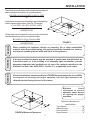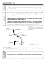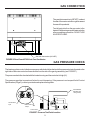
1
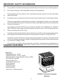
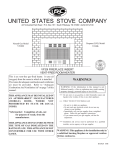
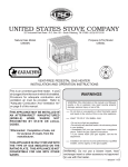
USSC
E
ATES ST
ED ST
OV
NIT
U
COMPANY
UNITED STATES STOVE COMPANY
227 Industrial Park Road • P.O. Box 151 • South Pittsburg, TN 37380 • (423) 837-2100
Natural Gas Model
A9740N
C9740N
G9740N
Propane (LPG) Model
A9740L
C9740L
G9740L
VENT-FREE PEDESTAL GAS HEATER
INSTALLATION AND OPERATION INSTRUCTIONS
This is an unvented gas-fired heater. It uses
air (oxygen) from the room in which it is installed.
Provisions for adequate combustion and
ventilation air must be provided. Refer to
"Adequate Combustion And Ventilation Air"
on page 6 of this manual.
THIS APPLIANCE MAY BE INSTALLED IN
AN AFTERMARKET* MANUFACTURED
(MOBILE)
HOME,
WHERE
NOT
PROHIBITED BY STATE OR LOCAL
CODES.
*Aftermarket: Completion of sale, not
for purpose of resale, from the
manufacturer.
THIS APPLIANCE IS ONLY FOR USE WITH
THE TYPE OF GAS INDICATED ON THE
RATING PLATE. THIS APPLIANCE IS NOT
CONVERTIBLE FOR USE WITH OTHER
GASES.
WARNINGS
WARNING: If the information in this manual is not
followed exactly, a fire or explosion may result causing
property damage, personal injury or loss of life.
Do not store or use gasoline or other flammable vapors
and liquids in the vicinity of this or any other appliance.
WHAT TO DO IF YOU SMELL GAS
• Do not try to light any appliance.
• Do not touch any electrical switch; do not use any phone
in your building.
• Immediately call your gas supplier from a neighbor's
phone. Follow the gas supplier's instructions.
• If you cannot reach your gas supplier, call the fire
department.
Installation and service must be performed by a qualified
installer, service agency or the gas supplier.
WARNING: Do not use a blower insert, heat
exchanger insert or other accessory not approved
for use with this heater.
851227C 9/98
TABLE OF CONTENTS
IMPORTANT SAFETY INFORMATION ............................................... .....3-4
PRODUCT FEATURES..........................................................................................4
SPECIFICATIONS ..................................................................................... ....5
CONTENTS ................................................................................................. 5
ITEMS REQUIRED FOR INSTALLATION.................................................. 6
INSTALLATION ........................................................................................... 7
GAS CONNECTION ................................................................................. 8-9
GAS PRESSURE CHECK............................................................................ 9
LOG ASSEMBLY ....................................................................................... 10
OPERATING INSTRUCTIONS............................................................... 11-13
CLEANING / SERVICING ...................................................................... 13-14
FLAME APPEARANCE ............................................................................. 14
PARTS LIST FOR HEATER ASSEMBLY.............................................. 15-16
PARTS LIST FOR BURNER & LOG ASSEMBLY......................................17-18
TROUBLE SHOOTING.......................................................................... 19-20
OPTIONAL EQUIPMENT.....................................................................................21
NOTE.......................................................................................................................22
NOTICE
LIMITED WARRANTY POLICY ................................................................ 23
Installation and repair must be done by a qualified service person. The appliance
should be inspected before use and at least annually by a professional service
person. More frequent cleaning may be required due to excessive lint from carpeting, bedding material, etc. It is imperative that control compartments, burners and
circulating air passageways of the appliance be kept clean.
TC
IMPORTANT SAFETY INFORMATION
INSTALLER: Please leave these instructions with the owner.
OWNER: Please retain these instructions for future reference.
WARNING
IMPORTANT: Read these instructions carefully before installing or trying to operate this heater.
WARNING: Any change to this heater or its controls can be dangerous. Improper
installation or use of the heater can cause serious injury or death from fire, burns,
explosion or carbon monoxide poisoning.
1.
CARBON MONOXIDE POISONING: Early signs of carbon monoxide poisoning are similar to the
flu with headaches, dizziness and/or nausea. If you have these signs, obtain fresh air immediately.
Have the heater serviced as it may not be operating properly.
2.
The installation must conform with local codes or, in the absence of local codes, with the National
Fuel Gas Code, ANSI Z223.1.
3.
The 9740N/9740L vent-free gas heater system cannot be installed in a bedroom.
4.
Do not install the heaters in a bathroom.
5.
WARNING: Improper installation, adjustment, alteration, service or maintenance can cause injury
or property damage. Refer to this owner's manual. Installation and service must be performed by
a qualified installer; service agency or the gas supplier.
6.
To prevent malfunction and/or sooting, an unvented gas heater should be cleaned at least annually
by a professional service person. More frequent cleaning may be required due to excessive lint from
carpeting, etc. It is imperative that control compartments, burners and circulating air passageways
be kept clean.
7.
Correct placement of the ceramic fiber logs is necessary to avoid problems with sooting. Sooting
can settle on surfaces outside the heater and cause discoloration. See the appropriate sections of
this manual for instructions.
8.
WARNING: Do not allow fans to blow directly into the fireplace. Avoid any drafts that alter burner
flame patterns. Do not place a blower inside burn area of firebox. Ceiling fans may create drafts
that alter burner flame patterns. Sooting and improper burning will occur.
9.
10.
This is an vent-free gas-fired heater. It uses air (oxygen) from the room in which it is installed.
Provisions for adequate combustion and ventilation air must be provided. Refer to installation
guidelines.
11.
Children and adults should be alerted to the hazard of high surface temperature and should stay
away to avoid burns or clothing ignition.
3
IMPORTANT SAFETY INFORMATION
12.
Young children should be carefully supervised when they are in the same room with the appliance.
13.
Do not place clothing or other flammable material near the appliance.
14.
Keep appliance area clear and free from combustible materials, gasoline and other flammable
vapors and liquids.
15.
Any safety screen or guard removed for servicing, must be replaced prior to operating the heater.
16.
This vent-free gas heater is intended to be smokeless. If logs appear to smoke, turn off the heater
and call a qualified service person. Initial burn off may cause slight smoke and odor during the first
four hours of operation.
17.
Input ratings are shown in BTU per hour and are for elevations up to 2,000 feet. For elevations
above 2,000 feet, input ratings should be reduced 4 percent for each 1,000 feet above sea level.
Refer to the National Fuel Gas Code.
18.
The heater and its individual shut off valve must be disconnected from the gas supply piping system
during any pressure testing of that system at test pressures in excess of 1/2 psig (3.5 kPa).
19.
The heater must be isolated from the gas supply piping system by closing its individual manual
shutoff valve during any pressure testing of the gas supply piping system at test pressures equal
to or less than 1/2 psig (3.5 kPa).
Do not use this room heater if any part has been under water. Immediately call a qualified service
technician FEATURES
to inspect the room heater and to replace any part of the control system and any gas
PRODUCT
control which has been under water.
Features:
• Heating Efficiency - 99.9%
• Wide BTU Range: 10,000 - 39,900.
• Safe Operation - Oxygen Depletion Sensor (ODS).
• No Electricity Required.
• Fibre Ceramic Logs.
• Push-Button Piezo Ignitor.
• Clean Operation.
• Wide Bay Front.
• Compact Design.
• Easy Operation.
• Heats up to 1,200 square feet.
FIGURE 1. 9740 Vent-Free Pedestal
Gas Heater.
4
SPECIFICATIONS
Natural Gas
Manifold Pressure Setting 4" w.c.
Gas Inlet Pressure
Maximum 10-1/2" w.c.
Minimum 5" w.c.
Model Number
Type
9740N
Manual
Number
of Burners
Gas Rate
Max BTU/Hr
Min BTU/Hr
39,900
10,000
2
Propane / LPG
Note: An external regulator is required to reduce supply pressure to a maximum of 13" w.c.
Manifold Pressure Setting 10" w.c.
Gas Inlet Pressure
Maximum 13" w.c.
Minimum 11" w.c.
Model Number
Type
9740L
Manual
Number
of Burners
Gas Rate
Max BTU/Hr
Min BTU/Hr
39,900
10,000
2
Controls - Main control has 4 positions:
1. OFF - All gas to the gas logs is shut off at the control
2. IGN - Piezo ignitor allows ignition of the pilot without the use of matches or batteries
3. PILOT - Valve position to light / maintain a standing pilot
4. ON - Gas flow to complete system, front burner ignition
Front Burner Control Knob - Infinite control, rotate clockwise to minimum rate and counter
clockwise for maximum rate.
Rear Burner Control Knob - Has 3 positions:
1. OFF - Gas to rear burner is shutoff at control
2. ON/MAX - Maximum gas flow to rear burner
3. MIN - Minimum gas flow rate to rear burner
CONTENTS
9740L and 9740N Unvented Gas Heaters
1. Packet containing Homeowners/Installation instructions.
2. Log box containing four (4) fiber ceramic logs, refer to installation instructions.
3. Unvented gas heater.
CAUTION
CHECK THAT ALL LISTED PARTS HAVE BEEN RECEIVED
GLOVES ARE RECOMMENDED WHEN HANDLING CERAMIC FIBER LOGS
TO PREVENT SKIN IRRITATION FROM LOOSE FIBERS. LOGS ARE
FRAGILE, HANDLE WITH CARE.
Carefully inspect the contents for shipping damage and immediately inform your dealer if any damage is found.
5
ITEMS REQUIRED FOR INSTALLATION
ITEMS REQUIRED FOR INSTALLATION
Ensure that the following items are available before proceeding with installation:
• External regulator (for propane/LPG only)
• Piping which complies with local codes
• Pipe sealant approved for use with
propane/LPG (resistant to sulfur compounds)
• Manual shutoff valve
• Sediment trap
• Pipe wrench
CODES
Adhere to all local codes or in their absence, the latest edition of THE NATIONAL FUEL GAS CODE ANSI Z223.1
or NFPA54 which can be obtained from:
WARNING
American National Standards Institute, Inc.
1430 Broadway
New York, NY 10018
or
National Fire Protection Association, Inc.
Batterymarch Park
Quincy, MA 02269
Due to high temperatures, do not install the heater:
• Where curtains, furniture, clothing or other flammable objects are less than 42"
from the front of the heater.
• In high traffic areas.
• In windy or drafty areas.
DO NOT PLACE CLOTHING OR OTHER FLAMMABLE MATERIAL ON OR NEAR THE
APPLIANCE.
ADEQUATE COMBUSTION AND VENTILATION AIR
This heater shall not be installed in a confined space or unusually tight construction unless provisions are provided
for adequate combustion and ventilation air.
Unusually tight construction is defined as construction where:
(a) Walls and ceilings exposed to the outside atmosphere have a continuous water vapor retarder with a rating
of 1 perm (6 x 10½11kg per pa-sec-m 2) or less with openings gasketed or sealed, and
(b) Weather stripping has been added on openable windows and doors, and
(c) Caulking or sealants are applied to areas such as joints around window and door frames, between sole
plates and floors, between wall-ceiling joints, between wall panels, at penetrations for plumbing, electrical,
and gas lines, and at other openings.
The National Fuel Gas Code defines a confined space as a space whose volume is less than 50 cubic feet per 1,000
BTU per hour (4.8m3per kw) of the aggregate input rating of all appliances installed in that space and an unconfined
space is defined as a space whose volume is not less than 50 cubic feet per 1,000 BTU per hour (4.8m3 per kw) of
the aggregate input rating of all appliances installed in that space. Rooms communicating directly with the space
in which the appliances are installed, through openings not furnished with doors, are considered a part of the
unconfined space.
6
INSTALLATION
The following formula can be used to determine the maximum
heater rating per the definition of unconfined space:
BTU/HR = (L1+L2) Ft x (W) Ft x (H) Ft x 1000
50
Consider two connecting rooms with an open area between,
with the following dimensions:(See Fig. 3, Example)
L1=15-1/2 Ft., L2=12 Ft., W=12 ft., H=8Ft
50
=52800 BTU/HR
H (8')
L2 (12')
W (12')
L1 (15-1/2')
WARNING
When installing the appliance directly on carpeting, tile or other combustible
material, other than wood flooring, the appliance must be installed on a metal or
wood panel extending the full width and depth of the appliance.
WARNING
FIGURE 3.
If the area in which the heater may be operated is smaller than that defined as an
unconfined space or if the building is of unusually tight construction, provide
adequate combustion and ventilation air by one of the methods described in the
National Fuel Gas Code, ANSI Z223.1, Section 5.3, or applicable local codes.
WARNING
If there were a door between the two rooms the calculation
would be based only on the room with the heater.
BTU/HR=(15-1/2) x (12) x (8) x 1000
50
=29760 BTU/HR
Ensure the minimum clearances shown in FIGURE 4 are maintained for accessibility
for purposes of servicing and proper operation. Left and right clearances are
determined when facing the front of the heater.
Maintain
these
clearances to ensure
adequate space around
air opening for proper
operation.
36"
8"
8"
Minimum clearances to
combustibles:
Top of heater.................................36"
Sides of heater...............................8"
Front of heater.............................42"
Rear of heater................................4"
42"
4"
FIGURE 4. Minimum Clearances
7
CAUTION
NOTICE
GAS CONNECTION
A qualified gas appliance installer must connect the fireplace to the gas supply.
Consult all local codes.
Use new black iron or steel pipe only. Internally tinned copper tubing can be used
in some areas when permitted by local codes. Only use pipe of 1/2" or greater
diameter to allow full gas volume to heater. Excessive pressure loss will occur if the
pipe is too small.
A manual shutoff valve, union and plugged 1/8" NPT pressure tapping point must be
installed upstream of the heater (FIGURE 5).
A sediment trap must be installed upstream of the heater to prevent moisture and
contaminants from passing through the pipe to the heater controls and burners.
Failure to do so could prevent the heater from operating reliably (FIGURE 5).
TO HEATER
CONTROL VALVE
IMPORTANT: Loosen the pipe adapter
on the flex tube before installing to the
system piping.
STAINLESS
FLEXIBLE TUBE
PIPE
MANUAL
SHUTOFF VALVE
PIPE
COUPLING
TEE JOINT
SEDIMENT TRAP
PIPE NIPPLE
CAP
FIGURE 5. Gas Connection
WARNING
CHECK GAS TYPE: The gas supply must be the same as stated on heater's rating plate. If the gas supply is
different, DO NOT INSTALL the heater. Contact your dealer for the correct model.
Connecting directly to an unregulated propane/LPG tank can cause an explosion.
8
GAS CONNECTION
The gas inlet connection is 3/8" NPT, made at
the rear of the main control through the area at
the rear of the pedestal.
Test all gas joints from the gas meter to the
heater for leaks using soap and water solution
after completing connection. DO NOT USE
AN OPEN FLAME.
Gas Inlet Connection (3/8" NPT)
FIGURE 6. Rear View of 9740 Vent-Free Gas Heater
GAS PRESSURE CHECK
The heater regulator controls the burner pressure which should be checked at the pressure test point located on the
right side of the main control and is accessible from the side of the gas log assembly (see FIGURE 7).
The pressure should be checked with the heater burning and the control set to high (HI).
The pressure regulator is preset and locked to avoid tampering. If the pressure is not as specified in Product
Specifications (Page 5), contact your dealer and replace the regulator.
Control Bracket
(Rightside view
facing heater)
Test Pressure
Input
Test Pressure
Output
Control Valve
FIGURE 7. Pressure Test Point Location
9