1
Operating Instructions and Parts Manual
Manual de instrucciones de operación y piezas
Modelos para pozos profundos
Shallow Well Models
Please read and save these instructions. Read carefully before attempting to assemble, install, operate or maintain the product described.
Protect yourself and others by observing all safety information. Failure to comply with instructions could result in personal injury and/or property damage! Retain instructions for future reference.
Jet Pump Water Systems
Garantía Limitada
Durante un año a partir de la fecha de compra, Wayne Home Equipment ("Wayne") reparará o reemplazará,
según lo consideren adecuadon, cualquier pieza de esta bomba para sumideros (“Producto”) que el comprador original envie a reparación y los empleados o representantes autorizados de Wayne determinen que
están defectuosos debido a problemas de materiales o manufactura. Para recibir información sobre los pasos
a seguir, comuníquese directamente con la compañía Wayne (800-237-0987, sólo desde EE.UU.), o con el distribuidor autorizado más cercano a su domicilio. En el momento de reclamar sus derechos bajo esta garantía
deberá suministrarnos el número del modelo. Todos los gastos de flete serán la responsabilidad del comprador.
Esta garantía limitada no cubre los daños debido a accidentes, abusos, uso inadecuado, negligencia, instalación inadecuada, mantenimiento inadecuado, o funcionamiento sin seguir las instrucciones suministradas
por escrito por la compañía Wayne.
NO HAY NINGUNA OTRA GARANTIA EXPRESA O IMPLISITA. INCLUYENDO AQUELLAS SOBRE VENTA O
USOS ESPECIFICOS, Y LAS GARANTIAS ESTAN LIMITADAS A UN AÑO A PARTIR DE LA FECHA DE COMPRA. ESTA ES LA UNICA GARANTIA Y CUALQUIER PERDIDA O RESPONSABILIDAD CIVIL, SEA DIRECTA
O INDIRECTA COMO CONSECUENCIA DE DAÑOS SON EXCLUIDAS.
Algunos estados no permiten límites en la duración de las garantías, o no permiten que se limiten o excluyan
casos por daños por accidentes o consecuentes, en dichos casos los límites arriba enumerados tal vez no
apliquen para Ud. Esta garantía limitada le otorga a Ud. ciertos derechos que pueden variar de un estado a
otro.
Bajo ninguna circunstyancia, aunque sea debido al incumplimiento del contrato de garantía, culpabilidad (incluyendo negligencia) u otras causas,la compañía Wayne o ninguno de sus surtidores serán responsables
legalmente por ningún fallo legal en su contra, incluyendo, pero no limitado apérdida de ganancias, pérdidas
del uso del producto o piezas asociadas con el equipo, pérdidas de capital, gastos para reemplazar los productos dañados, pérdidas por cierre de fábrica, servicios o pérdida de electricidad, o demandas persentadas
por los clientes del comprador por dichos daños.
Ud. DEBE conservar el recibo como prueba de compra junto con esta garantía. En caso de que necesite presentar un reclamo de sus derechos bajo esta garantía, Ud DEBERA enviar una copia del recibo de la tienda
junto con el producto o correspondencia. Comuníquese con la compañía Wayne (800-237-0987, sólo desde
EE.UU) para recibir autorización e instrucciones de como enviar la mercancía.
NO ENVIE ESTOS DATOS A WAYNE. Conserve esto sólo como datos.
MODEL NO._______________ NO. DE SERIE __________________________ FECHA DE INSTALACION_____________
GRAPE SU RECIBO DE COMPRA AQUI
Description
Shallow well jet pumps are single stage
domestic water pumps designed for
pumping portable water in applications
where the water is located less than 25
feet vertically from the pump. A pressure switch is a standard feature. The
shallow well pump can be mounted to
either a precharged, conventional type
or free standing pressure tank.
Unpacking
After unpacking the jet pump, carefully
inspect for any damage that may have
occurred during transit. Check for
loose, missing or damaged parts.
Safety Guidelines
This manual contains information that
is very important to know and understand. This information is provided for
SAFETY and to PREVENT EQUIPMENT
PROBLEMS. To help recognize this
information, observe the following
symbols.
Danger indicates
an imminently hazardous situation which, if not avoided,
will result in death or serious injury.
!
DANGER
Warning indicates
!
a potentially hazardous situation which, if not avoided,
could result in death or serious injury.
WARNING
Caution indicates a
!
potentially hazardous situation which, if not avoided,
may result in minor or moderate injury.
CAUTION
Notice indicates
important information, that if not followed, may cause
damage to equipment.
NOTICE
General Safety
Information
1. Read the instruction manual included
with the product carefully. Be thor-
© 2000 Wayne Home Equipment
32 Sp
oughly familiar with the controls and
the proper use of the equipment.
2. Know the pump application, limitations and potential hazards.
Always install a
pressure relief valve
to match the system pressure rating and
the maximum flow rate.
Do not use to pump
!
flammable or explosive fluids such as gasoline, fuel oil,
kerosene, etc. Do not use in explosive
atmospheres. Pump should only be used
with liquids compatible with pump component materials. Failure to follow this
warning can result in personal injury
and/or property damage.
Disconnect power
!
and release all pressure from the system before attempting
to install, service, relocate or perform any
maintenance. Lock the power disconnect
in the open position. Tag the power disconnect to prevent unexpected application of power.
Install a screen
!
around the inlet
pipe to prevent entrapment of swimmers.
! WARNING
WARNING
WARNING
WARNING
3. Drain all liquids from the system
before servicing.
4. Secure the discharge line before
starting the pump. An unsecured discharge line will whip and possibly
cause personal injury and/or property
damage.
5. Check hoses for weak or worn condition before each use. Make certain
all connections are secure.
6. Periodically inspect pump and system
components. Perform routine maintenance as required (See
Maintenance).
7. Personal Safety:
a.
Wear safety glasses at all times
when working with pumps.
b.
Keep work area clean, uncluttered and properly lighted replace all unused tools and
equipment.
c.
Keep visitors at a safe distance
from work area.
d.
Make the workshop childproof
use padlocks, master switches
and remove starter keys.
8. Do not pump chemicals or corrosive
liquids. Pumping these liquids
shortens the life of the pumps seals
and moving parts and will void the
warranty.
9. When installing pump, cover the
well to prevent foreign matter
from falling into well and contaminating the water and damaging
internal mechanical pumping components.
10. Always test the water from the
well for purity before use. Check
with local health department for
test procedure.
11. Complete pump and piping system
MUST be protected against below
freezing temperature. Freezing
temperatures could cause severe
damage and void the warranty.
12. Do not run the pump dry or damage will occur and will void warranty.
Risk of electrical
!
shock. This pump is
designed for indoor installation only.
WARNING
All wiring should be
!
performed by a
licensed or certified electrician.
WARNING
13. For maximum safety, the unit
should be connected to a grounded
circuit equipped with a ground
fault interrupter device.
14. Before installing the pump, have
the electrical outlet checked by a
licensed or certified electrician to
make sure the outlet is properly
grounded.
15. Make sure the line voltage and frequency of electrical current supply
agrees with the motor wiring.
16. Do not attempt repairs to the electric
motor. All repairs to the motor must
be completed at a licensed or certified electrical motor repair shop.
340102-001 9/00
Operating Instructions and Parts Manual
General Safety
Information (Cont’d)
Do not touch an
operating motor.
Modern motors are designed to operate at
high temperatures.
! WARNING
17. Avoid kinking electrical cord and
protect from sharp objects, hot surfaces, oil and chemicals. Replace or
repair damaged or worn cords
immediately.
Disconnect power
!
and release all pressure from the system before attempting
to install, service, relocate or perform any
maintenance. Lock the power disconnect
in the open position. Tag the power disconnect to prevent unexpected application of power.
WARNING
18. Keep fingers and foreign objects
away from ventilation and other
openings. Do not insert any objects
into the motor.
Risk of electric
!
shock! Never connect the green (or green and yellow wire)
to a live terminal!
WARNING
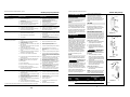
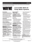
19. To reduce the risk of electrical
shock, the pump should be plugged
directly into a properly installed and
grounded 3-prong grounding type
receptacle, as shown in Figure 1.
The green (or green and yellow)
conductor in the cord is the grounding wire. The motor must be
securely and adequately grounded
for protection against shock.
Grounded
Pin
22. Use wire of adequate size to minimize voltage drop at the motor.
Do not handle
!
pump or pump
motor with wet hands, when standing
on a wet or damp surface or when
standing in water. Fatal electrical
shock could occur.
DANGER
RESET
Grounded Outlet
20. Where a 2-prong is encountered,
replace the plug with a properly
grounded 3-prong receptacle in
accordance with the National
Electrical Code, local codes and ordinances. To ensure a proper ground,
the grounding means must be tested by a licensed or certified electrician.
21. Use only 3-wire extension cords that
have a 3-prong, grounding type
plug, and 3-pole receptacles that
accept the equipment plug.
Air Volume
Control
Pump motor is
equipped with an
automatic resetting thermal protector and
may restart unexpectedly. Protector tripping is an indication of motor overloading
because of operating pump at low heads
(low discharge restriction), excessively
high or low voltage, inadequate wiring,
incorrect motor connections or defective
motor or pump.
! WARNING
Pre-Installation
Manual de instrucciones de operación y piezas
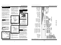
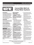
The water supplies illustrated in Figure
12 are possible sources for water.
These water supplies can be divided
into two categories:
SURFACE WATER
Water from a lake, stream, pond and
cistern. This water is usually not fit for
human consumption, but may be suitable for washing, irrigation or other
household uses.
GROUND WATER
Water found in the water bearing stratum at various levels beneath the earth.
Of all the fresh water found on earth
only 3 percent is found on the surface
and 97 percent is underground.
The function of the tank is to store a
quantity of water under pressure.
When full, the tank contains approximately 2/3 water and 1/3 compressed
air. The compressed air forces the
water out of the tank when a faucet is
opened. An air volume control auto-
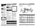
Puede escribirnos a:
Wayne Home Equipment
100 Production Drive
Harrison, OH 45030 U.S.A.
Sírvase proporcionar la suguiente información:
- Número de modelo
- Número de serie (si tiene)
- Descripción y número de repuesto como se muestra
en la lista de repuestos
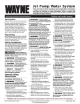
2
1
3
4
7
6
Bladder
12
8
5
10
11
13
14
Conventional
Tank
Precharged
Tank
9
20
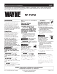
TANKS - PRECHARGED STORAGE
A precharged storage tank has a flexible bladder or diaphragm that acts as a
barrier between the compressed air
and water. This barrier prevents the air
from being absorbed into the water
and allows the water to be acted on by
compressed air at initially higher than
atmospheric pressures (precharged).
More usable water is provided than
with a conventional type tank.
Precharged tanks are specified in terms
of a conventional tank. For example, a
20 gallon precharged tank will have
the same usable water or drawdown
capacity as a 40 gallon conventional
tank, but the tank is smaller in size
(Figure 2).
PRESSURE SWITCH
The pressure switch provides for automatic operation. The pump starts
when pressure drops to a cut-in setting.
The pump stops when pressure reaches
a cut-out setting.
CHART 1 - JET PUMP/TANK ASSEMBLIES
Type
Air Volume
Control
Required
Well X
Precharged
PCA
Precharged
No
12P & 30P Horizontal
Conventional
Yes
FX Horizontal
Precharged
No
2
Modelos para pozos profundos
Para Piezas de Repuestos, Llame al 1-800-237-0987
Figure 2 - Conventional & Precharged
Storage Tanks
WATER SUPPLIES
TANKS - CONVENTIONAL STORAGE
TEST
Figure 1
Shallow Well Jet Pump
matically replaces air lost or absorbed
into the water. The usable water, or
drawdown capacity, of the tank is
approximately 1/6 of the tanks total
volume when operated on a “20-40”
pressure setting (Figure 2).
No
15
16
19
16
21
18
17
No. de
Ref.
1
2
3
4
5
6
7
8
9
10
11
12
13
14
15
16
17
18
19
20
21
•
Descripción
Motor
Tornillo
Placa de sellado
• Empaquetadura cuadrada de caucho para anillo
• Ensamblaje de sello del eje
Impulsor
Difusor
Tornillo
• Anillo en o
Venturi
Boquilla
19,1 mm (3/4”) Tapón de cebado
Voluta
6,4 mm (1/4”) NPT Tapón de cebado
3,2 mm (1/8”) NPT Tapón de cebado
Conector con manga
Base
4,8 mm (3/16”) Tubería
Presostato (Incluyes #22)
4,8 mm (3/16”) x 7,9 mm (5/16”) - 24 Tuerca
de compresión
Tuerca de cierre del conducto NPT de 12,7 mm (1/2”)
Juego para reparaciones (Incluyes #4, 5 y 9)
Para Los Modelos
SWS50-1/2 HP
SWS75-3/4 HP
SWS100-1 HP
23198-003
16636-002
17145-001
17150-001
56393
56876
17148-001
67007-001
15557
17151-002
15672
15921
56869-001
16314-002
15766-002
67009-001
23029-001
68001-001
56188
67010-001
23198-004
16636-002
17145-001
17150-001
56393
56876
17148-001
67007-001
15557
17151-003
15672
15921
56869-001
16314-002
15766-002
67009-001
23029-001
68001-001
56188
67010-001
23198-006
16636-002
17145-001
17150-001
56393
56875
17148-001
67007-001
15557
17151-004
15672
15921
56869-001
16314-002
15766-002
67009-001
23029-001
68001-001
56188
67010-001
1
4
1
1
1
1
1
2
1
1
1
1
1
1
1
1
1
1
1
1
12910
56874-001
12910
56874-001
12910
56874-001
1
1
31 Sp
Ctd.
Manual de instrucciones de operación y piezas
Modelos para pozos profundos
Guía de Diagnóstico de Averías
Operating Instructions and Parts Manual
Pre-Installation (Cont’d)
Problema
Posible(s) Causa(s)
Acción a Tomar
La bomba no funciona
1.
No hay energía eléctrica
1.
2.
El fusible se ha quemado o el interruptor se ha
desconectado
Interruptor de presión fallado
El tubo del interruptor a presión esta obstruído
Desconectado por sobrecarga del motor
2.
PACKAGE SYSTEMS
3.
4.
5.
3.
4.
5.
Encienda la corriente eléctrica o llame a la
compañía de suministro eléctrico
Cambie el fusible o vuelva a conectar el
interruptor de circuito
Cambie el interruptor
Limpie o reemplace la tubería de cobre
Deje que se enfríe. La sobrecarga se
recalibrará automáticamente
El motor suena pero no funciona
1.
2.
3.
Bajo voltaje en la línea
El cableado es demasíado pequeño
Los daños o la falta de alineamiento dan lugar
que las piezas rotatorías se peguen
1.
2.
3.
Haga un nuevo cableado. Ver la Table 3*
Haga un nuevo cableado. Ver la Table 3*
Reemplácelas o llévelas a un taller de
servicio para reparaciones
Desconexión por sobrecarga
1.
2.
Voltaje incorrecto en la línea
Los daños o la falta de alineamiento dan lugar
que las piezas rotatorias se peguen
1.
2.
3.
Alta temperatura en los alredodores
3.
4.
Ciclos rápidos
4.
Haga un nuevo cableado. Ver la Table 3*
Lleve el motor a un taller de reparaciones o
localice donde se pegan las piezas y haga las
reparaciones
Coloque la bomba en una zona sombreada
y bien ventilada
Vea la sección sobre bombas que funcionan y
se detienon con demasiada frecuencia
La bomba funciona pero no agua
o provee muy poca cantidad
1.
2.
3.
4.
5.
6.
7.
8.
9.
La bomba se prende y apaga continuamente
El nivel de agua está por debajo de la toma de la
bomba
La válvula de control está demasiado abierta
(pozos profundos)
Al cebar no se purgó la descarga
Hay fuga en la tubería en el lado del pozo donde
está la bomba
Está obsstruida la malla de la bomba o el colador
de aspiración de entrada
Boquilla obstruida (pozos profundos)
1.
Baje más el tubo de succión dentro del pozo
2.
Repita el procedimiento para cobar
3.
4.
Abra el grifo y vuelva a cebar
Repare la tubería según sea necesario
5.
Límpieia o reemplácela según sea necesario
6.
Se ha roto el diafragma del control del volumen
de aire
La válvula de aspiración puede estar obstruida o
atascada en la posición de cerrada
La bomba no se ha cebado completamente
7.
Jale el eyector de chorro y limpie la
obstrucción
Repare o cambie el control del volumen de
aire
Límpieia o reemplaceia según sea necesario
8.
9.
10. La válvula de control está completamente cerrada
(pozos profundos)
11. Nivel de agua por debajo de lo requerido para
aspirar
12. Tubería de tamaño menor que el requerido
13. Pozo gaseoso
10.
14. Venturi distorsionado
15. Eyector de chorro inadecuado para la aplicación
14.
15.
11.
12.
13.
Continúe cebando, haga una pausa cada 5
minutos para que se enfríe el armazón de la
bomba. Vuelva a llenar la bomba según sea
necesario
Ajuste la válvula de control según el procedimlento para cebar los pozos profundos
Seleccione el ensamblado de la bomba y/o
del eyector de chor ro que correspondan
Reemplace según sea necesario
Instale un deflector en la entrada a la bomba
para evitar que los gases entren al sistema
Inspecciónelo y reemplácelo
Adquiera un eyector de chor ro que encaje
en su sistema cuando esté reemplazando
una bomba de otra marca
Aumente el caballaje de la bomba
Aumente el diámetro de la tubería de succion o disminuya la fricción en la tubería
16. Bomba de tamaño muy pequeño
17. La bomba forma vacios parclales, suena como si
estuviera bombeando cascajo
16.
17.
1.
Tanque inundado (Convencional)
1.
2.
2.
Cambie el tanque o el control del volumen
de aire
Límpiela o reemplácela según sea necesario
3.
Mueva a la apertura correcta de la bomba
4.
5.
6.
7.
Agregue o quite aire cuanto sea necesario
Cambie el tanque
Localie y repare la fuga
Retire y reemplace
8.
La tubería del control del volumen de aire está
doblada u obtruida
Control de volumen de aire conectado a la salida
incorrecta de la bomba
Precarga de tanqueincorrecta (Tanque precargado)
Diafragma o bolsa rota (Tanque precargado)
Fuga enla tubería de la casa
Válvula de pie o válvula de retención atascada en
posición abierta
El motor se desconecta por sobrecarga
8.
9.
Interruptor de presión incorrectamente ajustado
Vea la sección sobre desconexiones por
sobrecarga
Reajuste o cambie el interruptor
3.
4.
5.
6.
7.
* Todas las conexiones eléctricas las debe hacer un electricista certificado o con licencia
30 Sp
9.
There are four jet pump/tank assemblies sold as packages (Chart 1).
Shallow Well Jet Pump
Unions or hose couplings can be
installed near pump to facilitate
removal for servicing or storage. A
rubber hose installed between the
water system and the house piping will
reduce the noise transmitted to the
house.
WELLS
PIPE SIZES
A new well should be pumped clear of
sand before installing the pump. Sand
will damage the pumping parts and
seal. The drawdown level of the well
should not exceed the maximum rated
depth for the pump. The capacity of
the pump will be reduced and a loss of
prime may occur.
Long horizontal pipe runs and an
abundance of fittings and couplers
decrease water pressure due to friction
loss. See Chart 2 to determine the
proper pipe size.
Installation
LOCATION
Select a location as close to the water
supply as possible. Be sure to comply
with any state or local codes regarding
the placement of the pump. The
equipment must be protected from the
elements. A basement, frost proof pit
or heated pump house are good locations. Make sure the pump has proper
ventilation. The temperature surrounding the pump is not to exceed
100° F (40°C) or nuisance tripping of
the motor overload may occur.
PIPING
Piping may be copper, steel, rigid PVC
plastic or flexible polyethylene plastic.
Flexible pipe is not
!
recommended on
suction pipe (inlet pipe).
CAUTION
The pipe must be clean and free of rust
or scale. Use a pipe joint compound on
the male threads of the metal pipe.
Teflon® tape should be used with plastic threads. All connections must be air
tight to insure normal operation.
Slope all inlet piping upwards towards
the pump to prevent trapping air.
To Pump
Well
Seal
Well
Casing
Foot
Valve
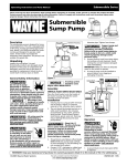
SHALLOW WELL INSTALLATION
A shallow well pump can be used when
the pump is located within 25 feet vertically of the water level. Shallow well
pumps have only one pipe between the
pump and the water supply (Figure 3).
Illustration A
To Pump
DRILLED WELL (FIGURE 12)
1. Install a foot valve on the first section
of pipe (Figure 3, Illustration A).
2. Lower the pipe into the well.
3. Add pipe until the foot valve is 5
feet below the lowest anticipated
water level.
Packer
Type
Foot
Valve
The foot valve
!
should be at least
18” from the bottom of the well or
sand or sediment could be drawn into
the system.
CAUTION
4. After proper depth is reached,
install a well seal or pitless adapter
to support pipe and prevent surface
water and other contaminants from
entering well.
Drive
Point
Illustration B
5. Slope the horizontal pipe upward
toward the pump to eliminate trapping air. Sloping the pipe will also
aid in priming the pump.
To Pump
DRIVEN WELL (FIGURE 12)
Incline
Check
Valve
1. Drive the point several feet below
the water table.
NOTE: A packer type foot valve can be
installed in the well (Figure 3, Illustration B). This type of foot valve allows
CHART 2 - PIPE SIZING
Pump
Model
Pump
Opening
0-25
Drive
Point
Horizontal Distance
(Feet)
26-100
100-300
Illustration C
Shallow Well Inlet
Outlet
11/4”
11/2”
2”
3/4”
1”
11/4”
3
Figure 3
Operating Instructions and Parts Manual
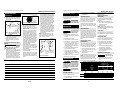
DUG WELL, CISTERN, LAKE AND SPRING
INSTALLATION (FIGURE 12)
Inlet
Outlet
Motor
Pressure
Range
Screw
1/4” Slip
On
Terminals
Figure 7a - Electrical Connections
Ground
Screw
Line
CAUTION
Figure 5 - Vertical Tank
Prime
Plug
Prime
Plug
Drain
Fitting
Inlet
Hose
Coupling
Figure 6 - Precharged Storage Tank
Outlet
Figure 4 - Horizontal Tank
Air
Volume
Control
1. Shut off the power to the pump.
2. Open the faucet nearest the tank
and allow all water to drain from
the tank.
3. Measure the tank precharge at the
valve stem using a tire pressure
gauge.
4. If necessary, precharge with an air
pump to 28 - 30 psi on 1/2, 3/4 and 1
HP pumps.
1. Install air volume control on tank.
4
WARNING
A metal underground water pipe or
well casing at least 10 feet long makes
the best ground electrode. If plastic
pipe or insulated fittings are used, run
a wire directly to the metal well casing
or use a ground electrode furnished by
the power company.
There is only one proper ground terminal on the unit. The terminal(s) is
located under the pressure switch
cover, is painted green and is identified
as GRD. The ground connection must
be made at this terminal (Figure 7a or
(F) CISTERNA:
Un tanque subterráneo
construido para recolectar
agua de lluvias de los
techos. El agua no es
apta para consumo
humano.
Air
Volume
Control
Tubing
Do not connect to
!
electric power supply until unit is permanently grounded.
Connect ground wire to approved ground
then connect terminal provided.
Figura 12 - Suministros de Agua
29 Sp
(F) CISTERNA
Pressure
Switch
28-30 psi
3/4 HP & 1 HP
CAPA FREATICA
SHALLOW WELL PUMP WITH CONVENTIONAL STORAGE TANK
(FIGURES 4 & 5)
Nozzle
Cleanout
Drain
Fitting
(E) POZO
PERFORADO
! WARNING
Select the proper size wire and fuse
(Chart 3). Time delay fuses are recommended over standard fuses for motor
circuit protection. All pump motors
have built-in automatic overload protection that will prevent damage to the
motor due to overheating.
ARCILLA
Inlet
TIERRA
SUPERFICIAL
Outlet
Ground
MATERIAL
PERMEABLE
Motor
Ground
Figure 7b - Electrical Connections
(D) POZO
ACCIONADO
SHALLOW WELL PUMP WITH
PRECHARGED STORAGE TANK
(FIGURE 6)
(E) POZO PERFORADO:
Un hoyo perforado en
la tierra con maquinaria y
revestido con tuberías.
Las profundidades
fluctúan entre algunos
pies hasta más de 305 m
(1000 pies). Los diámetros
comunes son 5,1 cm (2"),
7,6 cm (3"), 10,2 cm (4") y
15,2 cm (6") para pozos
de agua de uso doméstico.
Install a screen
around the inlet
pipe to prevent the entrapment of swimmers.
Customer
Power
Supply
Line
ARENA
ACUIFERA
Protect the pipe from damage from
swimmers and boats.
To
Motor
(D) POZO ACCIONADO:
Se acciona una tubería
con una pantalla con
punta en la tierra, por
debajo de la capa
freática. La profundidad
por lo general es menor
a 15,25 m (50 pies).
Los diámetros comunes
fluctúan entre 2,5 cm (1")
y 5,1 cm (2")
NOTE: When a lake is used as a water
supply, make sure the inlet pipe is deep
enough to be submerged at all times.
Slope the horizontal piping upward
toward the pump to prevent trapping
air. The pipe must be removed during
winter months or protected against
freezing.
Hose
Coupling
Suministros de Agua
The foot valve
!
should be at least
18” from the bottom of the well or
sand or sediment could be drawn into
the system.
Optional
Ground
(C) POZO EXCAVADO:
Se excava un hoyo de
varios pies de diámetro
hasta una profundidad
basante superficial.
Luego se reviste con
ladrillo, piedra o
concreto para evitar
que se derrumbe.
1. Install a foot valve on inlet pipe and
lower into water.
WARNING
(C) POZO EXCAVADO
Air
Volume
Control
Air Volume
Control
Tubing
Risk of electrical
!
shock. This pump is
designed for indoor installation only.
(A) MANANTIAL
4. Provide a hose bib (faucet) at the
lowest point in the system to drain
the system for service or storage.
Electrical
Modelos para pozos profundos
(B) LAGO,
ARROYO,
ESTANQUE
Leaking joints or couplings will allow
air to leak into the pipe and cause
abnormal pump operation. Make sure
to use pipe joint compound on all male
pipe threads.
3. Install a valve and an isolator hose
between the tank and the house
plumbing to aid in pump removal
for servicing and for reducing the
noise transmitted to the house
thrugh the piping.
(B) LAGO, ARROYO o ESTANQUE:
Agua superficial, que a menos
que sea tratada, por lo general
no es apta para consumo
humano. Puede ser utilizada
para fines tales como lavado
o irrigación.
As an alternative, an in-line check valve
can be used with a driven well (Figure
3, Illustration C). The pipe between the
check valve and the water level will
always be under a vacuum.
5. Slope the horizontal pipes upward
toward the pump to prevent trapping air. If the horizontal distance
exceeds 25 feet, see Chart 2 for the
recommended pipe size.
ESQUISTO
the well to be filled with water when
priming and makes the inlet pipe much
easier to test for leaks. Follow the
manufacturer’s instructions when
installing the packer type foot valve.
2. Connect the copper tube from the
air volume control to the uppermost
1/8” NPT opening on the side of
pump. Be sure the connections are
tight. Leaking can cause the pump
not to prime.
Manual de instrucciones de operación y piezas
(A) MANANTIAL:
Un manantial que emerge
de la tierra. Ocurre cuando
el agua en materiales
permeables está atrapada
entre materiales
impermeables tales como
roca o arcilla.
Installation (Cont’d)
Shallow Well Jet Pump
Manual de instrucciones de operación y piezas
Mantenimiento
Modelos para pozos profundos
en la cavidad del sello en la placa de
sellado. Use una rondana de cartón
(Continuacion)
Orificios para
los Tornillos
8. Planquee la pieza rotatoria de sellado del eje para que salga del impulsor (Figura 9).
Pieza Rotatoria
de Sellado del Impulsor
Eje
Eje del
Motor
Place de
Sellado
Figura 10 - Reemplazo de la Placa Sellado
Anillo de
Caucho de
Asentamiento
Asentamiento
de Cerámica
Figura 9 - Remoción del Sello del Eje
y el Asentamiento de
Cerámica
9. Empuje o palanquee el asentamiento de cerámica para separarlo de la
placa de sellado (Figura 9).
10. Elimine las partículas sueltas del
núcleo del impulsor y la placa de
sellado.
INSTALACIÓN DE UN NUEVO SELLO
DEL EJE
Antes de
!
manipular las piezas del sello del eje límpiese
las manos con un paño. El polvo y la
grasa pueden dañar el sello.
PRECAUCION
1. Humedezca con aceite de cocina, la
parte interior de la cavidad del sello
en la placa de sellado y los
empaques de caucho acopados que
rodean el nuevo asentamiento de
cerámica. Tenga cuidado de no raspar la superficie de cerámica del
asentamiento del sello y empuje el
asentamiento incluido en el caucho
para proteger la superficie pulida
cuando empuje contra el asentamiento de cerámica con cualquier
objeto. Cerciórese de sacar la rondana de cartón.
2. Deslice con cuidado la placa de sellado sobre el eje de modo que no se
mueva el sello de su posición en la
placa de sellado. Durante el ensamblado, la placa de sellado debe estar
orientada de modo que los dos orificios estén en una línea horizontal a
través del eje del motor y que las cuatro (4) clavijas de localización de la
parte posterior estén alineadas con
las lengüetas del armazón del motor
(Figura 10). Esta ubicación se debe
hacer para asegurar un drenaje y
cebado adecuados.
3. Sitúe la pieza rotatoria del sello del
eje en el impulsor y presiónela para
que quede en su sitio. Tenga cuidado
de no presionar contra la superficie
pulida del sello.
4. Coloque el impulsor en el eje y ajústelo bien (Figura 11).
5. Sasegure el difusor en la placa de sellado con los dos pernos. Cerciórese de
que los pernos estén orientados horizontalmente como se describe en el
paso 2.
6. Coloque con cuidado la empquetadura de la cubierta en espiral (voluta)
sobre el difusor en la placa de sellado.
En todas las aplicaciones de conversión, el anillo de sellado también
debe estar colocado sobre el difusor.
En todas las aplicaciones en pozos
poco profundos se debe tener cuidado de que los anillos en o (juntas tóricas) estén limpios y colocados adecuadamente sobre el Venturi. La
limpieza y la colocación correcta
hacen que exista un uen sellado dentro del difusor cuando se ensambla.
7. Acople la cubierta en espiral (voluta)
de la bomba al motor con los cuatro
pernos. Asegúrese de que la empaquetadura de la cubierta en espiral
(voluta) esté bien colocada y ajuste
bien los pernos.
NOTA: El eje debe poder girar libremente y la cubierta del extremo del
motor debe estar asegurada antes de
hacer funcionar la bomba.
Placa de Sellado Motor
Asentamiento
del Sello
Impulsor
Operating Instructions and Parts Manual
Electrical (Cont’d)
7b). The ground conductor must not
be smaller than the circuit conductors
supplying the motor.
Disconnect power
!
and release all pressure from the system before attempting
to install, service, relocate or perform any
maintenance.
WARNING
Para que el Sellado Sea
Adecuado, es Necesario
que la Cara del Sello este
Limpia
Figura 11 - Eje del Motor
shut off at the desired cut-off and will be
adjusted correctly.
DRAINING THE TANK
WATERLOGGED TANKS:
PRECHARGED
Conventional tanks can be drained by
opening an outlet at the lowest point
in the system. Remove plug or the air
volume control to vent the tank.
Operation
PRIMING THE SHALLOW WELL PUMP
RESTARTING PUMP
To prevent damage
!
to the pump, do not
start motor until pump has been filled
with water.
WARNING
1. Remove prime plug (Figure 4 or 5).
2. Fill pump and piping completely full
of water.
3. Replace the prime plug.
If the pump has been serviced, drained
or has not been used for some time, be
sure there is water in the pump housing (volute) and the piping to the well.
There must be water in the pump housing (volute) at all times when the pump
is running to avoid internal damage of
seal members (Priming the Shallow
Well).
4. Open a faucet to vent the system.
5. Start the motor. Water will pump in
a few minutes. If pump fails to
prime in 5 minutes, stop motor and
refill pump with water. Priming
time is proportional to the amount
of air in inlet pipe.
7. Close faucet and allow pump to
build pressure in tank. When the
pressure reaches the cut-out setting,
the motor will stop.
The system is now in operation and will
automatically cycle on demand.
Maintenance
Notas
2. Drain all piping to a point below
the freeze line.
Precharged tanks force virtually all the
water from the tank when system pressure is released. No draining is necessary.
6. Let the system operate for several
minutes to flush all pipes.
Asentamiento
del Sello
Shallow Well Jet Pump
WATERLOGGED TANKS:
CONVENTIONAL
When a tank system has an inadequate
ratio of air and water, the pump will
start and stop often and eradically.
28 Sp
NOTE: Once a bladder is leaking or broken, the bladder cannot be repaired. The
tank must be replaced.
LUBRICATION
The bearings used in the pumps are lifetime lubricated at the factory and require
no additional lubrication.
PRECHARGED TANK
Some air is lost through the bladder in
any tank. To prevent tank failure, check
the tank precharge on a yearly basis.
1. Open a faucet nearest the tank and
allow all water to drain from the
tank.
2. Open the lowest faucet in the system to release all pressurized water
in the system.
3. If necessary, adjust the precharge
with an air pump 28 - 30 psi on 1/2,
3/4 and 1 HP pumps.
3. Prime the pump (Priming the
Shallow Well).
REMOVING OLD SHAFT SEAL
4. Reconnect the power to the pump.
NOTE: As the pump refills the tank with
water, the air volume control supplies
the tank with the correct air to water
ratio for the system to operate. If the air
volume control is good, the pump will
!
CAUTION
Turn disconnect
switch to “off” posi-
tion.
1. Open a faucet nearest the tank and
allow all water to drain from the
tank.
CHART 3 - RECOMMENDED FUSE & WIRING DATA - 60 HZ MOTORS
Distance In Feet
From Meter To Motor
Dual
Element
Fuse
HP
DRAINING THE PUMP
1/2
Drain openings are provided on all
models. To drain the pump:
3/4
1. Remove drain plug and prime plug
to vent the system.
2. Replace the tank.
2. Measure the tank precharge at the
valve stem using a tire gauge.
WARNING
CAUTION
1. Test the tank by depressing the air
valve. The air valve will expel water if
the bladder is broken.
1. Disconnect the power to the pump.
Disconnect power
!
and release all pressure from the system before attempting
to install, service, relocate or perform any
maintenance. Lock the power disconnect
in the open position. Tag the power disconnect to prevent unexpected application of power.
Protect the pump
!
from freezing during winter conditions.
If a precharged tank becomes waterlogged, the bladder is normally leaking
or broken.
1
Volt
0
To
50
51
To
100
14
14
14
14
12
14
14
14
14
14
12
14
250V
115
230
115
230
115
230
15
10
15
10
20
10
5
101
To
200
201
To
300
Wire Size
12
14
10
14
10
14
10
14
8
14
8
14