1
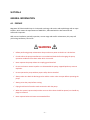
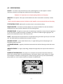
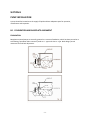
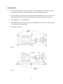
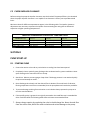
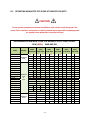
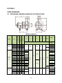
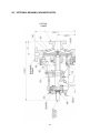
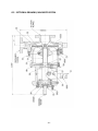
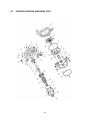
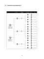
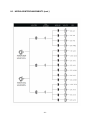
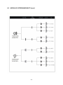
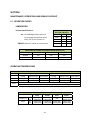
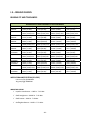
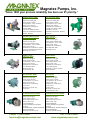
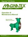
Magnatex® 3575 Series
Operation &
Maintenance Manual
Mechanical Seal
ANSI Process Pumps
Phone: 713-972-8666
[email protected]
Fax: 713-972-8665
www.magnatexpumps.com
TABLE OF CONTENTS SECTION A GENERAL INFORMATION A.1 Preface …………………………………………………………………………………………………….…………….… 1 A.2 Specifications …………………………………………………………………………………………………………..… 2 A.3 Receiving and Inspecting the Pump ……………………………………………………………………….… 3 SECTION B PUMP INSTALLATION B.1 Foundation and Baseplate Alignment ………………………………………..…………………….……… 4 B.2 Alignment ………………………………………………………………………………………………..…………….… 6 SECTION C PREPARATION FOR STARTUP C.1 Checking Rotation ……………………………………………………………………..……………………………… 6 C.2 Checking Impeller Clearance …………………………………………………………….……………………… 7 SECTION D PUMP STARTUP D.1 Starting the Pump ………………………………………………………………………………….………………… 7 D.2 Operating a Magnatex 3575 Pump at Reduced Capacity ............................................. 8 SECTION E PUMP DISASSEMBLY E.1 Recommended Spare Parts …………………………………………………….………………………………… 9 E.2 Required Tools ……………………………………………………………………………….…………….………… 10 E.3 Disassembly ………………………………………………………………………………………….………………… 10 SECTION PUMP ASSEMBLY F.1 Bearing Frame Assembly ……………………………………………………………….…………….…………… 12 F.2 Rotating Element Assembly ……………………………………………………………….………………..…… 12 SECTION G PUMP DRAWINGS G.1 Dimensional Drawing, Magnatex 3575 Series Pump …………………..………….……………… 14 G.2 Sectional Drawing, Magnatex 3575S …………………………………..…………….…………………… 15 G.3 Sectional Drawing, Magnatex 3575M ……………………………………………………….…………… 16 G.4 Sectional Drawing, Magnatex 3575L ………………………….……………………………..…………… 17 G.5 Exploded Drawing, Magnatex 3575S ………………………………..……………………….…………… 18 G.6 Exploded Drawing, Magnatex 3575M …………………………………….……………………………… 19 G.7 Exploded Drawing, Magnatex 3575L …………………………………………….………..……………… 20 SECTION H PUMP PARTS H.1 Modular Interchangeability ……………………………………………………………….…..……………… 21 H.2 Parts List and Materials of Construction …………………………………………………..…….……… 24 SECTION I MAINTENANCE, OPERATIONS AND REBUILD CHECKLIST I.1 Operations checks …………………………………………………………………….……………….…………….. 26 I.2 Impeller Clearance Settings ……………………………………………………………………………………… 27 I.3 Rebuild checks ……………………………………………………………………………….……………………... 29 SECTION A GENERAL INFORMATION A.1 PREFACE Magnatex 3575 Series ANSI Pump is a horizontal overhung, end suction and top discharge with an open impeller, which meets the requirements of ANSI B73.1, fabricated with the best materials and continuous inspection. With correct installation, periodic inspection, correct usage and careful maintenance, this pump will yield a long satisfactory service life. WARNING 9 Before performing pump maintenance always make sure power to the driver is locked out. 9 Consult either the pump manufacturer or an authorized dealer before changing the pump operation conditions from those under which it was sold. 9 Never operate the pump without its coupling guard installed. 9 Do not use heat to remove impeller or to disassemble the pump, trapped liquid may cause an explosion. 9 Do not operate the pump without proper safety devices installed. 9 Always make sure both the discharge valve and the suction valve are open before operating the pump. 9 Always prime the pump before starting. 9 Piping should not be forced to make connection with the pump. 9 When the system is pressurized, neither vent nor drain valves should be opened, nor should any plugs be removed. 9 Never operate below minimum recommended flow. ‐ 1 ‐ A.2 SPECIFICATIONS VOLUTE: The volute is top centerline with a fully confined gasket. The foot support is used for maximum resistance to misalignment and distortion from piping loads. However it is important not to impart piping loads on to the pump. IMPELLER: The impeller is fully open and threaded to the shaft. The threads are sealed by a Teflon O‐ ring. Never rotate the pump counter clockwise as the impeller can unscrew and rub on the casing. STUFFING BOX COVER: Machined for mechanical seal or conventional packing. FRAME ADAPTER: The ductile iron frame adapter has a machined rabbet fit to the seal chamber / stuffing box cover and a precision dowel pin fit to the bearing frame. BEARING FRAME: Of rigid iron construction. No machining is required to convert from oil to grease or oil mist lubrication. Flood oil lubrication is standard. The oil level is viewed through a sight glass. The power end is sealed with an Inpro “VBX” labyrinth seal. SHAFT: Manufactured from 4140 steel with an adjustable bearing and a bolt type roll pin on the shaft end. The 316SS shaft (also available) does not require a sleeve. BEARING SUPPORT: Constructed of ductile iron, it is rigid and has grooves and openings for oil lubrication, grease or oil mist. OUTBOARD BEARING: Angularly locked and connected to the shaft and housing to ideal with thrust loads. INBOARD BEARING: Its rigid, simple design, adequate for high RPM, also requires little attention in service. NAMEPLATE INFORMATION: Each pump has a nameplate that provides information about the pump, such as pump model, size impeller diameter, construction material, serial number, etc., (Fig 1). The nameplate is located on the bearing frame. When ordering spare parts you will need to identify pump model, size, serial number and the item number of required parts. Fig 1 ‐ 2 ‐ A.3 RECEIVING AND INSPECTING THE PUMP Please inspect the pump as soon as it is received and check that everything is in order. File any claims with the transportation company. This is a weighty pump; lifting equipment must be able to adequately support the entire assembly (Fig 2, 3). M
Pump Model 911 a DANGER STORAGE REQUIREMENTS Proper storage of your MAGNATEX pump will insure that it is ready for service when needed. GENERAL RULE: Pumps with corrosive fluid application; the process side of the pump should be drained and flushed with water and blown dry using low pressure air flow. After pump is dry a suitable rust preventative should be applied to the interior of the process side of the pump, whenever idle for periods in excess of (1) month or less for humid environments. For oil lubricated pumps the used oil should be drained and the reservoir filled with fresh oil to the normal operating level. Pumps with sealed grease‐lubricated bearings do not require any special attention. SHORT TERM STORAGE: No special steps are required if the pump is stored indoors in a temperature controlled environment, for less that (6) months. Follow general rule, and rotate the pump shaft several times every 3 months. LONG TERM STORAGE: In excess of (6) months, all machined surfaces and bearing must be treated with a rust preservative. Rotation of the shaft will be required every 3 months. Refer to coupling and driver manufacturer to comply with their recommended long term storage procedures. Unit must be stored in a covered and dry location. For specific recommendations regarding your storage conditions contact MAGNATEX Pumps. ‐ 3 ‐ SECTION B PUMP INSTALLATION A pump should be located near the supply of liquid and have adequate space for operation, maintenance and inspection. B.1 FOUNDATION AND BASEPLATE ALIGNMENT FOUNDATION Baseplate mounted pumps are normally grouted on a concrete foundation, which has been poured on a solid footing; foundation bolts commonly used are J – type and sleeve – type. Both designs permit movement for final bolt adjustment. ‐ 4 ‐ LEVEL BASEPLATE A. Place one set of wedges or shims on each side of every foundation bolt. The wedges should extend between ¾” and 1 ½” above foundation to allow for adequate grouting. B. Remove liquid and / or debris from anchor bolt holes/sleeve before grouting. If the sleeve type bolts are being used, fill the sleeves with packing or rags to prevent grout from entering. C. Lower Baseplate on to foundation bolts. D. Level Baseplate to within 1/8” over length of the Baseplate and to within 1/16” over the width of the base by adjusting the wedges. E. Hand tighten the bolts. Fig. 6 Fig. 7 ‐ 5 ‐ B.2 ALIGNMENT INITIAL ALIGNMENT CHECKS: (Done prior to operation) 9 Check before grouting the Baseplate to be sure correct alignment is possible. 9 Check after Baseplate is grouted to see if grouting process has altered alignment. 9 After pipes are connected, check to see if strained connections have altered alignment. If so, eliminate piping strain to achieve optimal alignment. FINAL ALIGNMENT: 9 Alignment should be checked after first run when both pump and driver are at operating temperature. 9 Alignment should be checked periodically in accordance with plant operating procedures. 9 Good alignment should be checked periodically in accordance with plant operating procedures. 9 Good alignment is achieved when the dial indicator readings are 0.002 in or less. SECTION C PREPARATION FOR START‐UP DANGER Make sure driver power is locked out. Failure to lock out driver power may result in serious physical injury. C.1 CHECKING ROTATION 1. Make sure coupling hubs are securely fastened to shafts. 2. Jog driver just long enough to determine direction of rotation. Rotation must correspond to arrow on bearing housing. CAUTION Serious damage may result if pump is run in the wrong rotation. 3. Make sure to leave power turned off to the driver. ‐ 6 ‐ C.2 CHECK IMPELLER CLEARANCE Before starting the pump the impeller clearance must be checked. The pump efficiency is maintained when the proper impeller clearance is set. Impeller front clearance is factory set to predetermined limits. Minimum values for different temperatures appear in the following table. The impeller clearance adjustments are necessary to prevent the impeller from contacting the casing due to differential expansion at higher operating temperatures.. IMPELLER CLEARANCES FOR SERVICE TEMPERATURES SERVICE TEMPERATURE °F (°C) MAGNATEX 3575 S MAGNATEX 3575 M & 3575 L inches (mm.)
inches (mm.)
MAGNATEX 3575 M & XL inches (mm.)
To 200 °F ( 93°C ) 250 °F ( 93°C ‐121°C ) 0.005” (0.13 mm) 0.007” (0.18 mm) 0.008” (0.20 mm) 0.010” (0.26 mm) 0.010” (0.26 mm) 0.010” (0.26 mm) 300 °F ( 121°C ‐149°C ) 0.009” (0.23 mm) 0.010” (0.26 mm) 0.019” (0.48 mm) 350 °F (149°C ‐177°C ) 0.011” (0.28 mm) 0.010” (0.26 mm) 0.021” (0.53 mm) MODEL 911S .) MODEL 911M y 911LX SECTION D PUMP START‐UP D.1 STARTING PUMP 1. Ensure that suction valve and any recirculation or cooling lines have been opened. 2. Completely close or partially open discharge valve as determined by system conditions. Never open discharge valve more than 25% on startup. 3. Start driver. Observe pressure gauges. Stop driver if discharge pressure is not attained quickly. Re‐prime and attempt to restart. 4. Open discharge valve slowly until the desired flow is obtained. If normal levels of vibration, bearing temperature and noise are exceeded, shut the pump down and resolve the problems. 5. To prevent damage resulting from cavitation or recirculation always operate the pump at or near the rated conditions. 6. If the specific gravity is greater than originally assumed or the rated flow rate is exceeded the driver could overload. The following table shows minimum recommended flows. 7. Always change capacity by regulating the valve in the discharge line. Never throttle flow from the suction side, which can cause cavitation and serious damage to the pump. ‐ 7 ‐ D.2 OPERATING MAGNATEX 3575 PUMP AT REDUCED CAPACITY CAUTION Do not operate pump below minimum rated flows or with suction and/or discharge valve closed. These conditions could cause an explosive hazard due to vaporization of pumpage and can rapidly lead to pump failure and physical injury. RECOMMENDED MINIMUM FLOW FOR MAGNATEX 3575 SERIES PUMPS GPM |M3hr| MAX.IMP.DIA SIZES MODEL 1 x 1‐1/2 ‐ 6 1‐1/2 x 3 ‐ 6 2 x 3 ‐ 6 MAGNATEX 3575S 60HZ 50HZ 60HZ 50HZ 60HZ 50HZ 3560 RPM 2900 RPM 1780 RPM 1470 RPM 1180 RPM 960 RPM
10 2.3 5 1.1 3 0.66 1 20 4.6 9 2.1 5 1.1 2 0.48 40 9.1 25 5.9 9 2.1 3 0.66 1 x 1‐1/2 ‐ 8 20 4.6 13 2.9 5 1.1 2 0.48 1‐1/2 x 3 ‐ 8 40 9.1 23 5.2 6 1.3 2 0.48 3 x 4 ‐ 7 125 28.4 76 17.7 13 2.9 4 0.96 2 x 3 ‐ 8 60 13.6 35 7.9 9 2.1 4 0.96 180 41.1 100 22.7 31 7.1 43.1 104 23.6 26 5.9 11 2.5 3 x 4 ‐ 8 N/A 3 x 4 ‐ 8G 190 1 x 2 ‐ 10 40 9.1 22 4.9 5 1.1 3 1‐1/2 x 3 ‐10 80 18.2 56 12.7 14 3.2 6 200 45.4 73 16.6 19 4.3 6 200 45.4 181 41.1 50 11.3 20 2 x 3 ‐10 3 x 4‐10 3 x 4 ‐ 10H MAGNATEX 3575S & 3575L 17 3.8 0.66 3 0.66 1.3 5 1.1 1.3 3 0.66 4.6 12 2.7 N/A N/A 150 34.1 76 17.3 30 6.8 6 4 x 6 ‐ 10 N/A N/A 450 27.1 117 26.6 79 17.9 24 5.5 4 x 6 ‐ 10H N/A N/A 400 90.8 153 34.7 85 19.3 46 10.4 1.4 2.5 1‐1/2 x 3 ‐13 180 40.9 401 91.1 45 10.2 23 5.2 11 2 x 3 ‐ 13 240 54.5 647 146.9 63 14.3 37 8.4 18 4.1 3 x 4 ‐ 13 400 90.8 333 75.6 168 38.2 104 23.6 67 15.2 31 7.1 370 84.1 297 67.4 150 34.1 89 20.2 4 x 6 ‐ 13 N/A N/A 6 x 8 ‐ 13 N/A N/A 850 193.1 480 109.1 375 85.1 197 44.8 8 x 10 ‐ 13 N/A N/A 1200 272.5 975 221.4 570 129.4 383 87.1 1000 227.1 6 x 8 ‐ 15 8 x 10 ‐ 15 8 x 10 ‐ 15G MAGNATEX 3575XL N/A N/A N/A N/A N/A N/A N/A 1400 ‐ 8 ‐ 0.24 317.9 726 164.9 462 104.9 277 62.9 1400 317.9 1000 227.1 769 174.8 1375 312.2 847 192.4 603 137.2 Section E PUMP DISASSEMBLY CAUTION To Prevent Injury 9 Power to the driver should be locked out to prevent accidental startup. 9 Pump operator should be familiar with all safety precautions. 9 Protective equipment should always be worn in case pump is handling fluids that are hazardous and/or toxic. 9 Proper lifting methods should be employed when handling pump components. 9 Heavy work gloves should be worn when handling impellers as they have sharp edges. 9 Suction and discharge valves should remain open during operation. 9 All replacement parts should be available (see below). E.1 RECOMMENDED SPARE PARTS • Impeller • Shaft sleeve • Shaft • Outboard bearing • Inboard bearing • Inboard labyrinth seal • Outboard labyrinth seal • Gland stud nut • Bearing lock washer • Volute gasket • O‐ Ring bearing housing • Gasket – frame to adapter • Stuffing box packing • O‐ Ring impeller Process Pump Model 911 ‐ 9 ‐ E.2 REQUIRED TOOLS • Wrenches 7/16”, ½”, 9/16”, ¾”, 7/8”, and 15/16” • Screwdriver • Pliers • Rubber mallet • Allen wrenches • Snap‐ring pliers • Micrometer • Dial indicator • Bearing puller • Brass drift punch • Lifting sling • Induction bearing heater • Torque wrench • Heavy work gloves •Cleaning agents • Feeler gauges E.3 DISASSEMBLY Step 1 ‐ Drain all liquid from pump and flush if necessary. Disconnect all auxiliary piping and tubing. Step 2 ‐ Remove coupling guard and disconnect coupling. Step 3 ‐ If oil‐lubricated; drain oil from bearing frame by removing bearing frame drain plug. (Oil should be saved for analysis to assist preventative maintenance.) Replace plug after oil is drained. Step 4 ‐ Remove casing bolts and frame foot bolts. Step 5 ‐ Carefully remove back pull‐out assembly (requires assistance). Step 6 ‐ Remove jack screws. Mann Process Pump Model 911 Step 7 ‐ Remove volute gasket and discard. (Replace with new gasket during re‐assembly.) Step 8 ‐ Frame adapter should be secured to workbench. Step 9 ‐ Remove coupling hub. ‐ 10 ‐ Step 10 ‐ Removal of impeller: DANGER Wear heavy work gloves to prevent injury from sharp edges! 9 Remove impeller. 9 Slide shaft wrench over the shaft and key. 9 Looking from the impeller end of the shaft, rotate the impeller clockwise, raising the wrench off the work surface. 9 Now turn it quickly back the other way, banging the wrench handle on the workbench or a solid block until impeller comes loose. Step 11 ‐ Remove volute gasket and discard. (Replace with new gasket during re‐assembly.) Step 12 ‐ Remove seal chamber/stuffing box cover. Step 13 ‐ Remove seal gland/packing stuffing box Step 14 ‐ Remove the shaft sleeve. Step 15 ‐ Remove packing and lantern ring from the stuffing box cover. Step16 ‐ Remove the frame adapter by removing the dowel pins and bolts. Step 17 ‐ Discard gaskets (replace with new ones during reassembly). Step 18 ‐ Remove inboard labyrinth oil seal Step 19 ‐ Disassemble power end 9 Remove clamp screws, and begin to tighten jack screws to start the housing out of the bearing frame. 9 Slide shaft assembly out of bearing frame. 9 Remove the jack screw with nuts. 9 Remove bearing housing O‐Ring and bearing retaining snap ring. 9 Remove bearing housing from shaft. 9 From the bearing housing, remove the outboard labyrinth seal and O‐Rings. 9 From the shaft, remove the bearing locknut and washer, inboard bearing, and outboard bearing. Step 20 ‐ Remove all plugs from bearing frame, unbolt the feet, and remove. ‐ 11 ‐ SECTION F PUMP ASSEMBLY All pumps parts should be inspected before reassembly. Check that all parts are clean before assembly. F.1 ASSEMBLY OF BEARING FRAME Step 1 –Install all threaded plugs in bearing frame (sight oiler plug, for oil mist connection plug, oil fill plug, oil drain plug, relief plug and oil cooler inlet and outlet plugs. Step 2 –Install bearing frame foot and bolts, hand tighten. F.2 ASSEMBLY OF ROTATING ELEMENT Step 1 –For the models 3575S and 3575M: Install outboard bearing on shaft. Coat internal surfaces of bearings with lubricant that will be used in the pumps operations. Process Pump Model 911 The inboard bearing is installed with the shield away from impeller. For model 3575L: Install outboard bearing on shaft. For proper installation please check SKF catalog. Coat the internal surfaces of bearings with lubricant that will be used in pump operation. Step 2 –Place lock washer on shaft and tang of lock washer in keyway of shaft. Step 3 –Thread locknut onto shaft. Tighten locknut until tight. Bend washer tang aligning with slot of lock washer into the slot of locknut. Step 4 –For models 3575S and 3575M: Place bearing retaining ring for impeller end to outboard bearing. This bearing retaining ring is grooved; the flat face should be towards outboard bearing. For the model 3575L: Place bearing clamp ring over shaft (Note orientation). Step 5 –Install inboard bearing on shaft. Before installing, coat internal surfaces of the bearings with the lubricant to be used in pump operation. Step 6 –Install a new o‐ring in bearing housing. Step 7 –Coat outside of outboard bearing and inside of bearing housing with oil. Step 8 –Install the shaft/bearing assembly in the bearing housing. Step 9 –For model 3575S and 3575M: Secure the retaining ring in groove. Check that the groove in the bearing frame is not blocked by the retaining ring. ‐ 12 ‐ Step 10 –Check that the shaft turns freely. Step 11 –Before installing the outboard labyrinth seal, make sure that the grooved edges on the shaft are smooth in order to protect outboard labyrinth seal packing. Step 12 –Install outboard labyrinth seal in bearing housing with packing adjustment type “O”. The groove for oil drainage must be oriented downwards. Step 13 –Lubricate the outer track of the bearing housing, the inboard bearing and inner track of the bearing frame with the oil to be used during the pump operation. Step 14 –Install shaft assembly into frame. Check that the shaft turns freely. Mann Process Pump Model 911 Step 15 –Position the bearing housing in the bearing frame. Align the word “top” the upper portion of the bearing frame. Tighten the leveling screws and nuts by hand. Step 16 –Once the rotating element is installed in the bearing frame, place a dial indicator on the end of the shaft. Move shaft forward and backward to check axial movement. MAGNATEX 3575 SERIES SHAFT END PLAY in. (mm) 3575S 3575M 3575L min 0.0011(.028) 0.0013(.033) Double row N/A max 0.0019(.047) 0.0021(.054)
min *0.0007(.012) *0.0009(.022) 0.0010(.026) Duplex max 0.0010(.026) 0.0012(.030) 0.0015(.038)
3575XL 0.0014(.036) 0.0023(.058) *0.0010(.026) 0.0015(.038) Step 17 – Check shaft/sleeve run out. Install the shaft sleeve, if used, and then hand tighten impeller. Rotate shaft 360 degrees. Disassemble and determine cause if the total indicator reading is greater than 0.002 in. Step 18 – Check frame face run out. Rotate shaft so indicator rides along the fit for 360 °. If the total indicator reading is more than 0.001 in (0.025 mm) disassemble and troubleshoot. Step 19 – Install the gasket on the frame. Step 20 – Install the frame adapter onto frame assembly aligning bolt holes and dowel locations with the frame. Step 21 – Install dowel pins and bolts. Step 22 – Check adapter to determine if the total indicator reading is within tolerance. Step 23 – Install inboard labyrinth oil seal into adapter/bearing frame in the 6 o’clock position. Mann Process Pump Model 911 ‐ 13 ‐ SECTION G PUMP DRAWINGS G.1 DIMENSIONAL DRAWING MAGNATEX 3575 SERIES PUMPS SUCTION SIZE SIZE DISCHARGE SIZE FRAME ANSI DESIGNATION GENERAL DIMENSION A B C D E F BORE DIMENSIONS IN INCHES (CENTIMETERS) LBS (kgs.) 1x 1‐1/2 – 6 1‐1/2 x 3 – 6 MAGNATEX 3575S MAGNATEX 3575M & 3575L MAGNATEX 3575XL 2 x 3 – 6 AA AB 1 1.5 1.5 3 13.5 (34.3) 7.25 (18.5) 6 (15.2) .625 (1.58) 84 (38) 42 (92) 2 3 AA 1 1.5 1‐1/2 x 3 – 8 A8 1.5 3 3 x 4 – 7 A70 3 4 11 (28.0) 100 (220) 2 x 3 – 8 A60 2 3 9.5 (24.2) 200 (91) 3 x 4 – 8 A70 3 4 3 x 4 – 8G A70 3 4 1 x 2 – 10 A05 1 2 1‐1/2 x 3 –10 A50 1.5 3 2 x 3 –10 A60 2 3 9.5 (24.2) 3 x 4–10 A70 3 4 11 (28.0) 3 x 4 – 10H A40 3 4 12.5 (31.8) 4 x 6 – 10 A80 4 6 4 x 6 – 10H 1‐1/2 x 3 –13 2 x 3 – 13 A80 A20 A30 4 1.5 2 6 3 3 3 x 4 – 13 A40 3 4 1 x 1‐1/2 – 8 6.5 (16.5) .563 (1.43) 11 (28.0) 4 (10.2) 8.5 (21.6) 220 (91) 12.5 (31.8) 9.75 (24.7) .625 (1.58) 305 (138) 245 (111) 275 (125) 10 (25.4) 12.5 (31.8) A80 4 6 13.5 (34.3) A90 6 8 16 (40.6) 8 x 10 – 13 A100 8 10 6 x 8 – 15 A110 6 8 8 x 10 – 15 A120 8 10 8 x 10 – 15G A129 8 10 18 (45.7) 230 (104) 265 (120) 305 (138) 10.5 (26.7) 11.5 (29.2) 6 x 8 – 13 49 (108) 220 (100) 13.5 (34.3) 4 x 6 – 13 43 (95) 45 (100) 200 (100) 8.25 (21.0) 19.5 (49.5) 330 (150) .563 (1.43) 14.5 (36.8) 27.9 (70.8) 19 (48.3) 6 (15.2) 18.75 (47.6) 16 (40.6) 405 (184) 560 (254) 670 (304 .875 (2.22) 610 (277) 740 (336) 322 (710) ‐ 14 ‐ 5.25 (13.3) WEIGHT G.2 SECTIONAL DRAWING, MAGNATEX 3575S Mann Process Pump Model 911 SUCTION FLANGE odel911 ‐ 15 ‐ G.3 SECTIONAL DRAWING, MAGNATEX 3575M ‐ 16 ‐ G.4 SECTIONAL DRAWING, MAGNATEX 3575L Mann Process Pump Model 911 ‐ 17 ‐ G.5 EXPLODED DRAWING, MAGNATEX 3575S ‐ 18 ‐ G.6 EXPLODED DRAWING, MAGNATEX 3575M Mann Process Pump Model 911 ‐ 19 ‐ G.7 EXPLODED DRAWING, MAGNATEX 3575L Mann Process Pump Model 911 ADAPTER SEAL CHAMBER IMPELLER VOLUTE SIZE ‐ 20 ‐ H.1 MODULAR INTERCHANGEABILITY ‐ 21 ‐ H.1 MODULAR INTERCHANGEABILITY (cont.) ‐ 22 ‐ H.1 MODULAR INTERCHANGEABILITY (cont.) SEA ‐ 23 ‐ H.2 PARTS LIST AND MATERIALS OF CONSTRUCTION ITEM QTY PER PUMP 100 1 VOLUTE 101 1 IMPELLER 105 106 107 108 112 113A 122 122 126 134 136 168 184 228 236A 241 236A 250 253B 319 332A 333A 351 353 355 357K 358A 360D 360Q 361A 370 370B 370C 370D 370F 370H 382 408A 408H 408J 408L 408M 412A 418 423 469B 496 529 531 1 1 1 1 1 1 1 1 1 1 1 1 1 1 10 1 1 1 1 1 1 1 1 2 2 2 1 1 1 1 * 4 3 3 2 2 1 1 4 1 1 1 1 3 3 2 2 2 1 LANTERN RING STUFFING BOX PACKING GLAND FRAM ADAPTER THRUST BEARING PLUG – OIL FILL SOLID SHAFT NO SLEEVE (OPTIONAL) SHAFT WITH SLEEVE SHAFT SLEEVE BEARING HOUSING BEARING LOCKNUT RADIAL BEARING SEAL CHAMBER/STUFFING BOX COVER BEARING FRAME CAP SCREW FRAME FOOT OIL DEFLECTOR GLAND MECHANICAL SEAL BEARING CLAMP RING OIL SIGHT GLASS OUTBOARD LABYRINTH SEAL INBOARD LABYRINTH SEAL CASING GASKET GLAND STUD GLAND STUD NUT PLUG CASING DRAIN PLUG (OPTIONAL) GASKET – FRAME ADAPTER GASKET RETAINING RING BOLT – ADAPTER TO CASING BOLT – FRAME TO ADAPTER CLAMP BOLT – BEARING HOUSING JACK BOLT – BEARING HOUSING BOLT – FRAME FOOT TO FRAME STUD – STUFFING BOX COVER TO ADAPTER LOCK WASHER – BEARING PLUG – OIL DRAIN PLUG – OIL MIST CONNECTION PLUG OILER PLUG – OIL COOLER INLET PLUG – OIL COOLER OUTKLET O‐RING – IMPELLER JACKBOLT – ADAPTER TO CASE JAM NUT – BEARING HOUSING JACK BOLT DOWL PIN O‐RING – BEARING HOUSING LOCKWASHER FRAME FOOT TO BEARING FRAME PIN PART NAME * QTY DUCTILE IRON DUCTILE IRON WITH 316SS IMP 316SS ALLOY 20 CD4MCu MONEL HASTELOY B&C DUCTILE IRON 316SS ALLOY 20 CD4MCu MONEL B&C 316SS 316SS ALLOY 20 CD4MCu MONEL B&C DUCTILE IRON DUCTILE IRON 316SS DUCTILE IRON 316SS CARBON STEEL MODEL* QTY M353ODEL 4 MAGNATEX 3575S, with impeller diam. 6"ø 8 MAGNATEX 3575M, with impeller diam. 8"ø 8 MAGNATEX 3575L & MAGNATEX 3575M, with impeller diam. 8"ø 12 MAGNATEX 3575L & MAGNATEX 3575M, with impeller diam. 10"ø 16 MAGNATEX 3575L & MAGNATEX 3575M, with impeller diam. 13"ø ‐ 24 ‐ TEFLON TEFLON ALLOY 20 MONEL B&C DUCTILE IRON DOUBLE ROW ANGULAR CONTACT CARBON STEEL 316SS SAE ‐ 4140 316SS 316SS DUCTILE IRON STEEL SINGLE ROW DEEP GROVE 316SS ALLOY 20 CD4MCu MONEL B&C DUCTILE IRON CARBON STEEL DUCTILE IRON CARBON STEEL ALLOY 20 CARBON STEEL GLASS /STEEL BRONZE WITH VITON O‐RINGS BRONZE WITH VITON O‐RINGS ARAMID FIBRE WITH EDPM 316SS 304SS 304SS 316SS ALLOY 20 CD4MCu MONEL B&C VELLUMOID ARAMID FIBRE WITH EDPM STEEL CARBON STEEL CARBON STEEL CARBON STEEL CARBON STEEL CARBON STEEL 316SS STEEL STEEL STEEL STEEL STEEL STEEL TEFLON 304SS CARBON STEEL 1018 BUNA‐N STEEL STEEL SECTION I MAINTENANCE, OPERATIONS AND REBUILD CHECKLIST I.1 ‐ OPERATION CHECKS LUBRICATION MAGNATEX 3575 SERIES OIL SUMP CAPACITY Recommended lubricants: OIL: ISO VG68 High Quality turbine oil. For pumpage temperatures above 250°F (121°C) use synthetic oil GREASE: NLGI No.2, sodium or lithium based Model 3575S 3575M oz. 16 42 ml. 475 1250 3575L 48 1425 3575XL 96 2850 MAGNATEX 3575 SERIES RELUBRICATION INTERVALS (OIL) Power End Type Mineral Oil Synthetic Oil Regreaseable Standard 3mo. 6mo. 3mo. Sealed 3mo. 24mo. N/A OPERATING TEMPERATURES MAGNATEX 3575 SERIES MAXIMUM RECOMMENDED OPERATING TEMPERATURE Lubrication Flood Oil Oil Mist Grease Mineral Oil
Synthetic Oil Without With Finned With High Without With Finned With High Cooling Tube Oil Cooler Temp. Option Cooling Tube Oil Cooler Temp. Option 350°F (177°C) 500°F (260°C) 700°F (371°C) 450°F (232°C)
500°F (260°C) 700°F (371°C)
350°F (177°C) 500°F (260°C) 700°F (371°C) 450°F (232°C)
500°F (260°C) 700°F (371°C)
Up to 350°F (177°C) Standard Pump With No Modifications 350°F to 500°F (177°C to 260°C) High temperature Grease and Stuffing Box Cooling.
MAGNATEX 3575 SERIES SHAFT END PLAY in. (mm) Double row Duplex min max min max 3575S 0.0011(.028)
0.0019(.047) *0.0007(.012) 0.0010(.026) 3575M 3575L 3575XL 0.0013(.033) 0.0014(.036) N/A 0.0021(.054) 0.0023(.058) *0.0009(.022) 0.0010(.026) *0.0010(.026) 0.0012(.030) 0.0015(.038) 0.0015(.038) ‐ 25 ‐ I.2 – IMPELLER CLEARANCE SETTINGS It is imperative that these procedures for proper impeller clearance are followed. Improper setting of the impeller clearance can result in sparks, greater heat generation and equipment failure. WARNING Lock out driver power to prevent accidental startup and physical injury IMPELLER CLEARANCES MAGNATEX 3575 SERIES IMPELLER CLEARANCES Service Temperature ‐20 to 150°F (‐29 to 66°C) Up to 175°F (79°C) Up to 200°F (93°C) Up to 250°F (121°C) Up to 300°F (149°C) Up to 350°F (177°C) Up to 400°F (204°C) Up to 450°F (232°C) Up to 500°F (260°C) Up to 550°F (288°C) Up to 600°F (316°C) Up to 650°F (343°C) Up to 700°F (371°C) 3575S
inches
mm
0.005 0.13 0.005 0.13 0.005 0.13 0.006 0.16 0.007 0.19 0.009 0.22 0.010 0.25 0.012 0.28 0.013 0.30 0.014 0.33 0.015 0.36 0.016 0.39 0.017 0.42 3575M & 3575L
inches
mm
0.008 0.20 0.008 0.20 0.008 0.20 0.009 0.23 0.010 0.26 0.012 0.29 0.013 0.32 0.014 0.35 0.015 0.38 0.016 0.41 0.017 0.44 0.019 0.47 0.020 0.50 3575XL inches mm 0.015 0.38 0.015 0.38 0.015 0.38 0.016 0.41 0.015 0.44 0.015 0.47 0.015 0.50 0.015 0.53 0.015 0.56 0.015 0.59 0.015 0.62 0.015 0.65 0.015 0.68 DIAL INDICATOR METHOD 1. Remove coupling guard. 2. Remove coupling. 3. Set dial indicator to contact coupling face or shaft end. 4. Loosen locking bolt by backing bolts out several turns 5. Loosen jam nuts on the jack bolts, evenly turn jack bolts until impeller contacts the stuffing box or seal chamber. Slowly turn shaft to verify that contact has been made. ‐ 26 ‐ 6. Zero out dial indicator. 7. Evenly back off each jack bolt and tighten locking bolts to move the impeller away from the stuffing box cover or seal chamber until the dial indicator reads a .060” clearance. 8. Evenly turn jack bolts and tighten jam nuts. 9. Verify shaft turns freely. 10. Install Coupling. 11. Install Coupling guard. FEELER GAUGE METHOD 1. Remove coupling guard. 2. Remove coupling. 3. Loosen jam nuts on the jack bolts, evenly turn jack bolts until impeller contacts the stuffing box or seal chamber. Slowly turn shaft to verify that contact has been made. 4. Using feeler gauges measure gap between the bearing housing and the bearing frame for .060” clearance. 5. Evenly back off each jack bolt and tighten locking bolts to move the impeller away from the stuffing box cover or seal chamber until the dial indicator reads a .060” clearance. 6. Evenly turn jack bolts and tighten jam nuts. 7. Verify shaft turns freely. 8. Install Coupling. 9. Install Coupling guard. ALIGNMENT ‐ Coupling to be aligned to within 0.002in. T.I.R. for both parallel and angular readings. VIBRATION ‐ Maximum Vibration Level 0.25in/sec unfiltered at inboard and outboard bearing location. TEMPERATURE – Normal Power End operating temperature 120 to 180°F (50 to 82°C) ‐ 27 ‐ I.3 – REBUILD CHECKS BEARING FIT AND TOLERANCES MAGNATEX 3575 SERIES BEARING FIT AND TOLERANCES MODEL SHAFT O.D. INBOARD BEARING I.D. INBOARD FRAME I.D. INBOARD BEARING O.D. INBOARD SHAFT O.D. OUTBOARD BEARING I.D. OUTBOARD HOUSING I.D. OUTBOARD BEARING O.D. OUTBOARD 3575S in.(mm) 1.3785 (35.013) 1.3781 (35.002) 0.0010 (0.025) TIGHT 0.0001 (0.002) TIGHT 1.3780 (35.000) 1.3775 (34.988) 2.8346 (72.000) 2.8353 (71.987) 0.0012 (0.032) LOOSE 0.0000 (0.000) LOOSE 2.8346 (72.000) 2.8341 (71.987) 1.1815 ( 30.011) 1.1812 (30.002) 0.0008 (0.021)TIGHT 0.0001 (0.002)TIGHT 1.1811 (30.00) 1.1807 (29.990) 2.8346 (72.000) 2.8353 (72.019) 0.0012 (0.032) LOOSE 0.0000 (0.000) LOOSE 2.8346 (72.000) 2.8341 (71.987) 3575M in.(mm)
1.7722 (45.013)
1.7718 (45.002) 0.0010 (0.025) TIGHT
0.0001 (0.002) TIGHT 1.7717 (45.000)
1.7712 (44.988) 3.9370 (100.000)
3.9379 (100.022) 0.0015 (0.037) LOOSE
0.0000 (0.000) LOOSE 3.9370 (100.000)
3.9364 (99.985) 1.7722 (45.013)
1.7718 (45.002) 0.0010 (0.025)TIGHT
0.0001 (0.002)TIGHT 1.7717 (45.000)
1.7712 (44.002) 3.9370 (100.000)
3.9379 (100.022) 0.0015 (0.037) LOOSE
0.0000 (0.000) LOOSE 3.9370 (100.000)
3.9364 (99.985) IMPELLER BALANCE CRITERIA (ISO G6.3) 0.011 oz.in/lb. @ 3600RPM 18 g‐mm/kg @ 3600RPM INDICATOR CHECKS 9 Impeller Vane Runout – 0.005 in. T.I.R. Max. 9 Shaft Straightness – 0.0005 in. T.I.R. Max. 9 Shaft Runout – 0.002 in. T.I.R Max. 9 Stuffing Box Runout – 0.005 in. T.I.R. Max. ‐ 28 ‐ 3575L in.(mm)
2.1660 (55.015)
2.1655 (55.002) 0.0012 (0.030) TIGHT 0.0001 (0.002) TIGHT 2.1654 (55.000)
2.1648 (54.985) 4.7244 (120.000)
4.7253 (120.022) 0.0015 (0.037) LOOSE 0.0000 (0.000) LOOSE 4.7244 (120.000)
4.7238 (119.985) 1.9690 (50.013)
1.9686 (50.002) 0.0010 (0.025)TIGHT 0.0001 (0.002)TIGHT 1.9685 (50.000)
1.9680 (49.988) 4.3307 (110.000)
4.3316 (110.022) 0.0015 (0.037) LOOSE 0.0000 (0.000) LOOSE 4.3307 (110.000)
4.3301 (109.985) 3575XL in.(mm)
2.5597 (65.015)
2.5592 (65.002) 0.0012 (0.030) TIGHT
0.0001 (0.002) TIGHT 2.5591 (65.000)
2.5585 (64.985) 5.8118 ( 140.000)
5.5128 (140.025) 0.0017 (0.043) LOOSE
0.0000 (0.000) LOOSE 5.8118 (140.000)
5.5111 (139.982) 2.5597 (65.015)
2.5592 (65.002) 0.0012 (0.030)TIGHT
0.0001 (0.002)TIGHT 2.5591 (65.000)
2.5585 (64.985) 5.5118 (140.000)
5.5128 (140.025) 0.0017 ( 0.043) LOOSE 0.0000 (0.000) LOOSE 5.8118 (140.000)
5.5111 (139.982) TORQUE VALUES MAGNATEX 3575 SERIES TORQUE VALUES Location (370)Casing bolts (370B) Frame to Adapter Bolts Bearing Clamp ring Bolts (236A) Duplex bearing only (371C) Bearing End Covers (265) Dynamic Seal Cap Screw Lubricates Threads Dry Threads 30FT‐LBS (40 N∙m)
20FT‐LBS (27 N∙m)
30FT‐LBS (40 N∙m)
30FT‐LBS (40 N∙m)
20FT‐LBS (27 N∙m)
10IN‐LBS (1.1 N∙m)
55IN‐LBS (6.2 N∙m)
9FT‐LBS (12 N∙m)
45FT‐LBS (60 N∙m)
30FT‐LBS (40 N∙m)
45FT‐LBS (60 N∙m)
45FT‐LBS (60 N∙m)
30FT‐LBS (40 N∙m)
17IN‐LBS (1.9 N∙m)
83IN‐LBS (9.4 N∙m)
12FT‐LBS (16 N∙m)
55IN‐LBS (6.2 N∙m) 83IN‐LBS (9.4 N∙m) 9FT‐LBS (12 N∙m)
12FT‐LBS (16 N∙m)
6” 3575S
8” 3575S
3575L, 3575M
3575XL
3575S, 3575M
3575L
3575XL
3575S, 3575M, 3575L 3575XL
‐ 29 ‐ Magnatex Pumps, Inc.
“Since 1985 your process reliability has been our #1 priority.”
MAXP Series ANSI
3575 Series ANSI
(Magnetic Drive)
Max. Flow: 2000 gpm
Max. Head: 470 feet
Temperature: -150°F to 800°F
Max. Power: 200 hp
Materials of Construction:
Carbon Steel
304 & 316 Stainless Steel
Alloy 20, Hastelloy® equivalent,
Monel, Titanium
(Mechanical Seal)
Max. Flow: 5000 gpm
Max. Head: 720 feet
Temperature: up to 700°F
Max. Power: 300 hp
Materials of Construction:
Ductile Iron, Steel, 316SS,
CD4MCu, Alloy 20,
Hastelloy® equivalent, Ni-Hard,
Titanium
MP/MPL/MPH Series
Sub-ANSI / ANSI
MPT Series
(Magnetic Drive)
Max. Flow: 340 gpm
Max. Head: 400 feet TDH
Temperature: -100° to 536°F
Max. Power: 20 hp
Materials of Construction: 316 SS,
Alloy 20, Hastelloy® equivalent
Bearings: SiC, SiC-X
(Magnetic Drive)
Max. Flow: 40 gpm
Max. Head: 450 feet TDH
Temperature: -40° to 445°F
Max. Power: 20 hp
Materials of Construction:
316 Stainless Steel
Bearings: SiC-X
MMP Series
MEP Series
(Magnetic Drive)
Max. Flow: 20 gpm
Max. Head: 95 feet
Temperature: -100° to 536° F
Max. Power: 3/4 hp
Materials of Construction:
316 Stainless Steel
Bearings: SiC-X
Shaft: 316SS, SiC
(Magnetic Drive)
Max. Flow: 106 gpm
Max. Head: 103 feet
Max Temperature: 175° F
Max. Power: 3 hp
Materials of Construction:
GF Polypropylene
Bearings: C-PTFE, Carbon
Shaft: Ceramic
MTA Series ANSI
ME Series
(Magnetic Drive)
Max. Flow: 320 gpm
Max. Head: 285 feet
Temperature: 5° to 275°F
Max. Power: 25 hp
Materials of Construction:
PFA Lined
Bearings: C-PTFE, SiC
Shaft: SiC
(Magnetic Drive)
Max. Flow: 90 gpm
Max. Head: 140 feet
Temperature: 32° to 195° F
Max. Power: 3 hp
Materials of Construction:
ETFE Lined
PVDF Lined
Bearings: C-PTFE, SiC;
Shaft: Ceramic, SiC
S Series-Gear Pumps
SM Series-Gear Pumps
(Mechanical Seal)
Max. Flow: 30 gpm
Max. Head: 150 psi
Max Temperature: 450° F
Max. Power: 5 hp
Casing Materials:
316SS, Hastelloy® equivalent,
Ryton®
Shaft Materials: 316SS, Hastelloy®
Bearing Materials:
Carbon, Teflon®, Rulon®
(Magnetic Drive)
Max. Flow: 30 gpm
Max. Head: 110 psi
Max Temperature: 450° F
Max. Power: 5 hp
Casing Materials:
316SS, Hastelloy® equivalent,
Ryton®
Shaft Materials: 316SS,Hastelloy®
Bearing Materials:
Carbon, Teflon®, Rulon®
Phone: 713-972-8666
[email protected]
Fax: 713-972-8665
www.magnatexpumps.com