1
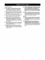
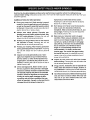
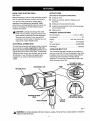
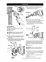
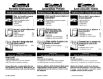
Owner's Manual
3/8 in. PROFESSIONAL
ELECTRIC DRILL
Variable Speed / Reversible
Double Insulated
Model No.
315.271690
Save this manual for
future reference.
•
•
•
•
•
• l, CAUTION:
Read and follow
all Safety Rules and Operating
Instructions before first use of
this product.
Customer
Sears,
Help Line: 1-800-932-3188
Roebuck
Visit the Craftsman
972000-718
2-00
and
Co.,
Hoffman
web page:
Estates,
IL 60179
Safety
Features
Operation
Maintenance
Parts List
USA
www.sears.com/craftsman
US
TABLE
OF CONTENTS
•
Table Of Contents ..........................................................................................................................................
•
General Safety Rules ...................................................................................................................
2-3
•
Specific Safety Rules/Symbols ...................................................................................................................
4-5
•
Features ......................................................................................................................................................
5-6
•
Operation ...................................................................................................................................................
•
Maintenance .................................................................................................................................................
11
•
Accessories ..................................................................................................................................................
12
•
Exploded View And Repair Parts List ..........................................................................................................
13
•
Parts Ordering / Service ...............................................................................................................................
14
WARNING:
Read and understand all instructions.
SAVETHESEINSTRUCTIONS
When operating a power tool outside, use an
outdoor extension cord marked "W-A" or "W."
These cords are rated for outdoor use and reduce
the risk of electric shock.
Work Area
Keep your work area clean and well lit. Cluttered benches and dark areas invite accidents.
•
Do not operate power tools In explosive
atmospheres, such as in the presence of
flammable liquids, gases, or dust. Power tools
create sparks which may ignite the dust or fumes.
•
Keep bystanders, children, and visitors away
while operating a power tool. Distractions can
cause you to lose control.
Electrical
•
•
•
•
Safety
Double insulated tools are equipped with a
polarized plug (one blade is wider than the
other). This plug will fit in a polarized outlet
only one way. If the plug does not fit fully in the
outlet, reverse the plug. If it still does not fit,
contact a qualified electrician to install a
polarized outlet. Do not change the plug in any
way. Double insulation [] eliminates the need for
the three-wire grounded power cord and grounded
power supply system.
Avoid body contact with grounded surfaces,
such as pipes, radiators, ranges, and refrigerators. There is an increased risk of electric shock if
your body is grounded.
Don't expose power tools to rain or wet conditions. Water entering a power tool will increase
the risk of electric shock.
Do not abuse the cord. Never use the cord to
carry the tools or pull the plug from an outlet.
7-10
Keep cord away from heat, oil, sharp edges, or
moving parts. Replace damaged cords immediately. Damaged cords increase the risk of electric
shock.
Failure to follow all instructionslisted below may
result in electric shock, fire, and/or serious personal
injury,
•
2
Personal
Safety
•
Stay alert, watch what you are doing, and use
common sense when operating a power tool.
Do not use tool while tired or under the influence of drugs, alcohol, or medication. A moment of inattention while operating power tools
may result in serious personal injury.
•
Dress properly. Do not wear loose clothing or
jewelry. Contain long hair. Keep your hair,
clothing, and gloves away from moving parts.
Loose clothes, jewelry, or long hair can be caught
in moving parts.
Avoid accidental starting. Be sure switch is off
before plugging in. Carrying toolswith your
finger on the switch or plugging in tools that have
the switch on invites accidents.
•
Remove adjusting keys or wrenches before
turning the tool on. A wrench or a key that is left
attached to a rotating part of the tool may result in
personal injury.
•
Do not overreach. Keep proper footing and
balance at all times. Proper footing and balance
enables better control of the tool in unexpected
situations.
•
Use safety equipment. Always wear eye protection. Dust mask, nonskid safety shoes, hard hat,
or hearing protection must be used for appropriate
conditions.
Tool Use and Care
•
Use clamps or other practical way to secure
and support the workpiece to a stable platform. Holding the work by hand or against your
body is unstable and may lead to loss of control,
•
Do not force tool. Use the correct tool for your
application. The correct tool will do the job better
and safer at the rate for which it is designed.
•
•
Check for misalignment or binding of moving
parts, breakage of parts, and any other condition that may affect the tool's operation. If
damaged, have the tool serviced before using.
Many accidents are caused by poorly maintained
tools.
•
Use only accessories that ere recommended
by the manufacturer for your model. Accessodes that may be suitable for one tool may become
hazardous when used on another tool.
Do not use tool if switch does not turn it on or
off. Any tool that cannot be controlled with the
switch is dangerous and must be repaired
•
Disconnect the plug from the power source
before making any adjustments, changing
accessories, or storing the tool. Such preventive safety measures reduce the risk of starting the
tool accidentally.
•
Store idle tools out of the reach of children and
other untrained persons. Tools are dangerous in
the hands of untrained users.
•
Maintain tools with care. Keep cutting tools
sharp and clean. Properly maintained tools with
sharp cutting edges are less likely to bind and are
easier to control.
Service
Tool service must be performed only by quali•
fied repair personnel. Service or maintenance
performed by unqualified personnel could result in
a risk of injury.
•
3
When servicing a tool, use only identical
replacement parts. Follow instructions in the
Maintenance section of this manual. Use of
unauthorized parts or failure to follow Maintenance
Instructions may create a risk of electric shock or
injury.
Hold tool by insulated gripping surfaces when performing an operation where the cutting tool may
contact hidden wiring or its cord. Contact with a "live" wire will make exposed metal parts of the tool "live" and
shock the operator.
Additional
•
•
Know your power tool. Read operator's manual
carefully. Learn its applications and limitations,
as well as the specific potential hazards related
to this tool. Following this rule will reduce the risk of
electric shock, fire, or serious injury.
Don't abuse cord. Never carry the tool by the
cord or yank it to disconnect it from the
receptacle. Keep cord away from heat, oil, and
sharp edges. Following this rule will reduce the
risk of electric shock or fire.
Always wear safety glasses. Everyday eyeglasses have only impact-resistant lenses; they
are NOT safety glasses. Following this rule will
reduce the risk of serious personal injury.
•
Protect your lungs. Wear s face or dust mask if
the operation is dusty. Following this rule will
reduce the risk of serious personal injury.
•
Protect your hearing. Wear hearing protection
during extended periods of operation. Following
this rule will reduce the risk of serious personal
•
replaced by an authorized service center.
Following this rule will reduce the risk of electric
shock, fire, or serious injury.
Rules for Safe Operation
•
length. A cord exceeding 100 feet is not
recommended. If in doubt, use the next
injury.
heavier gage. The smaller the gage number,
the heavier the cord. An undersized cord will
Inspect tool cords periodically and, if damaged, have repaired at your nearest Factory
Service Center or other Authorized Service
cause a drop in line voltage resulting in loss of
power end overheating.
Organization.
Constantly stay aware of cord
location. Following this rule will reduce the risk of
electric shock or fire.
•
Make sure your extension cord is in good
condition. When using an extension cord, be
sure to use one heavy enough to carry the
current your product will draw. A wire gage
size (A.W.G.) of at least 16 is recommended
for an extension cord 100 feet or less in
Check damaged parts. Before further use of
the tool, a guard or other part that is damaged
should be carefully checked to determine that it
will operate properly and perform its intended
function. Check for alignment of moving pads,
binding of moving parts, breakage of parts,
mounting, and any other conditions that may
affect its operation. A guard or other part that is
•
Inspect for and remove all nails from lumber
before drilling, Following this rule will reduce the
risk of serious personal injury.
•
Drugs, alcohol, medication. Do not operate tool
while under the influence of drugs, alcohol, or
any medication. Following this rule will reduce the
risk of electric shock, fire, or serious personal injury.
•
Save these instructions. Refer to them frequently
and use them to instruct others who may use
this tool. If you loan someone this tool, loan
them these instructions also.
damaged should be properly repaired or
4
SYMBOLS
SYMBOL
NAME
DESIGNATION/EXPLANATION
V
Volts
Voltage
A
Amperes
Current
Hz
Hertz
Frequency (cycles per second)
W
Watt
Power
rpin
Minutes
Time
"k.,
Alternating Current
Type or a characteristic of current
no
No Load Speed
Rotational speed, at no load
]
Class II Construction
Designates
Construction Double
tools Insulated
.../min
Revolutions or Reciprocation Per Minute
Revolutions, strokes,
surface speed, orbits etc. per minute
_1=
Safety Alert Symbol
Indicates danger, warning or caution.
It means attention!!! Your safety is
involved.
DEFINITIONS
A)
DANGER: Failure to obey a safety warning will result in serious injury to yourself or to
others. Always follow the safety precautions to reduce the risk of fire, electric shock and
personal injury.
B)
WARNING: Failure to obey a safety warning can result in serious injury to yourself or to
others. Always follow the safety precautions to reduce the risk of fire, electric shock and
personal injury.
C)
CAUTION: Failure to obey a safety warning may result in property damage or personal
injury to yourself or to others. Always follow the safety precautions to reduce the risk of fire,
electric shock and personal injury.
D)
NOTE: Advises you of information or instructions vital to the operation or maintenance of
the equipment.
5
KNOW YOUR ELECTRIC
APPLICATIONS
DRILL
See Figure 1.
(Use only for the purpose listed below)
Before attempting to use your drill, familiarize yourself
with all operating features and safety requirements.
•
Drilling in wood.
•
Drilling in ceramics, plastics, fiberglass, and
laminates.
•
Drilling in both hard and soft metals.
•
Using driving accessories, such as driving screws
with screwdriver bits.
•
Mixing paints.
Your drill has many features for making drilling
operations more pleasant and enjoyable. Safety,
performance, and dependability have been given top
priority in the design of this drill making it easy to
maintain and operate.
,_
CAUTION: Carefully read through this entire
owner's manual before using your new drill. Pay
close attention to the Rules For Safe Operation,
Warnings, and Cautions. If you use your drill
properly and only for what it is intended, you will
enjoy years of safe, reliable service.
ELECTRICAL
PRODUCT
SPECIFICATIONS
Chuck Capacity .................................
1/16 in. to 3/8 in.
Horsepower .............................................................
Rating .........................................
120 Volts, 60 Hz, AC
Input ........................................................
CONNECTION
1/2
5.5 Amperes
No Load Speed ........................................ 0-2500 RPM
Your drill has a precision built electric motor. It should
be connected to a power supply that is 120 volts,
60 Hz, AC only (normal household current). Do not
operate this tool on direct current (DC). A substantial
voltage drop will cause a loss of power and the motor
will overheat. If your drill does not operate when
plugged into an outlet, double-check the power
supply.
Net Weight ...................................................
3.875 Ibs.
LEVEL AND BELT CLIP
Two convenient features provided on your drill are a
level and a bert clip. The level is recessed in the motor
housing on your drill. It can be used to keep drill bits
level during both horizontal and vertical drilling
operations. The belt clip is molded into the top of the
motor housing on your drill.
TOP VIEWOF LEVEL
FOR HORIZONTALDRILLING
LEVEL
MOLDEDBELTCLIP
KEYLESSCHUCK
FORWARD-REVERSE
LEVER
ENDVIEWOF LEVEL
FORVERTICALDRILLING
SWlTCHTRIGGER
LOCK-ON
BUl"rON
Fig. 1
,_k
WARNING: Do not allow familiarity witt_tools to make you careless. Remember that a careless fraction of a second is
sufficient to inflict severe injury.
6
_L
WARNING: If any parts are missing, do not
operate this tool until the missing parts are
replaced. Failure to do so could result in possible
serious personal injury.
_IL
WARNING:
Always wear safety goggles or
safety glasses with side shields when operating
your drill. Failure to do so could result in dust,
shavings, loose particles or foreign objects being
thrown into your eyes, causing possible serious
injury.
DRILLBIT
RELEASE
(UNLOCK)
CHUCKBODY
CHUCK
JAWS
GRIP
(TIGHTEN)
CHUCK
COLLAR
Fig. 3
WARNING: Do not hold the chuck body with
one hand and use the power of the drill to tighten
chuck jaws on drill bit. The chuck body could slip
in your hand or your hand could slip and come in
contact with a rotating drill bit. This could cause
an accident resulting in serious personal injury.
SWITCH
REVERSIBLE
See Figure 4.
LOCK-ONBUTTON
Fig. 2
SWITCH
See Figure 2.
To turn your drill ON, depress the switch trigger.
Release switch trigger to turn your drill OFF.
LOCK-ON BUTTON
See Figure 2.
Your drill is equipped with a lock-on feature, which is
convenient when continuous drilling for extended
periods of time is required. To lock-on, depress the
switch trigger, push in and hold the lock-on button
located on the side of the handle, then release switch
trigger. Release lock-on button and your drill will
continue running.
Your electric drill has the feature of being reversible.
The direction of chuck rotation is controlled by a lever
located above the switch trigger, With your drill held in
normal operating position, the direction of rotation
lever should be positionedto the left of the switch for
drilling. The drill direction is reversed when the lever is
to the right of the switch.
The design of the switch will not permit changing the
direction of rotation while the drill is running. Release
the switch trigger and allow the drill to stop before
changing its direction.
Note: Your drill will not run unless the switch lever is
pushed tully to the left or right.
FORWARD-REVERSE
LEVER
REVERSE
To release the lock, depress the switch trigger and
release.
If you have the lock-on feature engaged during use
and your drill becomes disconnected from power
supply, disengage the lock-on feature immediately.
KEYLESS
CHUCK
See Figure 3,
Your new drill has a keyless chuck. As the name
implies, you can hand tighten or release drill bit in the
chuck jaws. Grasp and hold the collar of the chuck
with one hand. Rotate the chuck body with your other
hand. The arrows shown in figure 3 indicate which
direction to rotate the chuck body in order to GRIP
(tighten) or RELEASE (unlock) the drill bit.
FORWARD
Fig. 4
VARIABLE
SPEED
TO INSTALL
See Figure 5,
BITS
See Figure 6.
DRILLBIT
CHUCKJAWS
CHUCKBODY
CHUCKCOLLAR
TO INCREASESPEED,
PULLSWITCHTRIGGER
RIGHT
•
_
Fig. 5
I Fig. 6
Unplug your drill.
WARNING: Failure to unplug your drill could
result in accidental starting causing serious
injury.
•
Note: Depress switch trigger all the way for maximum
speed and torque of your drill. Depress switch trigger
only part of the way for less speed and torque.
Open or close the chuck jaws to a point where the
opening is slightly larger than the drill bit you
intend to use. Also, raise the front of your drill
slightly to keep the drill bit from falling out of the
chuck jaws.
•
Insert drill bit into chuck the full length of the jaws.
Avoid running your drill at low speeds for extended
periods of time. Running at low speeds under
constant usage may cause your drill to become
overheated. If this occurs, cool your drill by running it
without a load and at full speed.
,_k WARNING: Do not insert drill bit into chuck
jaws and tighten as shown in figure 7. This could
cause drill bit to be thrown from your drill
resulting in possible serious personal injury or
damage to your chuck.
Your drill has a variable speed switch designed to
allow operator control of speed and torque limits. The
speed and torque of your drill can be increased by
depressing the switch trigger.
The following guidelines may be used in determining
correct speed for various applications:
•
Low speed is idear when minimum speed and
power is required. For example, starting holes
without center punching, driving screws, mixing
paint, and drilling in ceramics.
•
Medium speed is suitable for drilling hard metals,
plastics, and laminates.
•
High speed produces best results when maximum
power is required. For example, drilling in wood;
soft metals such as aluminum, brass, and copper,
and when using driving accessories.
,_
WARNING: Your ddlr should never be
connected to power supply when you are
assembling parts, making adjustments, installing
or removing drill bits, cleaning, or when not in
use. Disconnecting your drill will prevent
accidental starting that could cause serious
personal injury.
•
Tighten the chuck jaws on drill bit.
•
To tighten: grasp and hold the collar of the chuck
with one hand, while rotating the chuck body with
your other hand.
Note: Rotate the chuck body in the direction of the
arrow marked GRIP to tighten chuck jaws.
•
8
Do not use a wrench to tighten or loosen the
chuck jaws.
TO REMOVE
•
_k
BITS
•
Depress and release switch trigger to be sure your
drill is in OFF position before connecting it to
power supply.
•
•
Check the direction of rotation lever for correct
setting (forward or reverse). See Figure 4.
Secure the material to be drilled in a vise or with
clamps to keep it from turning as the drill bit
rotates.
•
Plug your drill into power supply source.
•
Hold your drill firmly and place bit at point to be
drilled.
•
Depress the switch trigger to start your drill. Do not
lock the switch ON for jobs where your drill may
need to be stopped suddenly.
•
Move the drill bit into the workpiece applying only
enough pressure to keep the bit cutting. Do not
force your drill or apply side pressure tOelongate
a hole. Let your drill and bit do the work. See
Figures 8 and 9.
Unplug your drill
WARNING: Failure to unplug your drill
could result in accidental starting causing
serious injury.
•
Loosen
the chuck
jaws from drill bit.
•
To loosen: grasp and hold the collar of the chuck
with one hand, while rotating chuck body with your
other hand.
•
Note: Rotate the chuck body in the direction of the
arrow marked RELEASE
to loosen chuck jaws,
•
Do not use a wrench
chuck jaws.
•
Remove
to tighten or loosen the
drill bit from chuck jaws.
DRILLING
See Figures
8 and 9.
LEVEL
,_
WARNING: Be prepared for binding or bit
breakthrough. When these situations occur, drill
has a tendency to grab and kick opposite to the
direction of rotation and could cause loss of
control when breaking through materials. If not
prepared, this loss of control can result in
possible serious injury.
When drilling hard, smooth surfaces use a center
punch to mark the desired hole location. This will
prevent the drill bit from slipping off center as the hole
is started. However, the variable speed feature allows
starting holes without center punching if desired. To
accomplish this, operate your drill at a low speed until
the hole is started.
END VIEW
When drilling metals use a light oil on the drill bit to
keep it from overheating. The oil will prolong the life of
the bit and increase the drilling action.
If the bit jams in the work piece or if your drill stalls,
stop the tool immediately. Remove the bit from the
work piece and determine the reason for jamming.
LEVEL DRILLING
See Figures 8 and 9.
A convenient feature provided on your drill is a level. It
is recessed in the motor housing on your drill. It can
be used to keep drill bits level during both horizontal
and vertical drilling operations.
Fig. 8
TOPVIEW
•
Open the chuck jaws and remove hex key wrench.
Remove the chuck screw by turning it in a
clockwise direction, See Figure 1 I.
SCREWDRIVER
Fig. 11
Note: The chuck screw has Fefthand threads.
•
Insert hex key wrench into chuck and tighten chuck
jaws securely. Tap sharply with a mallet in a
counterclockwise direction. This will loosen the
chuck on the spindle, it can now be unscrewed by
hand, See Figure 12.
:ig. 9
CHUCK
REMOVAL
MALLET
See Figure 10, 11, and 12.
The chuck must be removed in order to use some
accessories. To remove:
•
,_k
•
•
CHUCK
Unplug your drill.
WARNING: Failure to unptug your drill could
result in accidental starting causing serious
injury.
HEX KEY
WRENCH
Insert a 8 mm (5/16 in.) or larger hex key wrench
into the chuck of your drill and tighten the chuck
jaws securely.
CHUCK
Tap the hex key wrench sharply with a mallet in a
clockwise direction. See Figure 10. This will loosen
the screw in the chuck for easy removal.
Fig. 12
The chuck may at times become loose on the spindle
and develop a wobble. Also, the chuck screw may
become loose causing the chuck jaws to bind and
prevent them from closing. To tighten, follow these
steps:
MALLET
CHUCKJAWS
CHUCK
•
,_k
HEXKEY
WRENCH
Unplug your drill.
WARNING: Failure to unplug your drill could
result in accidental starting causing serious
injury.
•
Insert hex key wrench into chuck and tighten chuck
jaws securely, Tap hex key wrench sharply with a
mallet in a clockwise direction. This will tighten the
chuck on the spindle.
•
Open the chuck jaws and remove the hex key
wrench.
•
Tighten the chuck screw,
Note: The chuck screw has left hand threads.
Fig. 10
10
GENERAL
DOUBLEINSULATION
All parts represent an important part of the double
insulation system and should be serviced only by a
qualified Sears service technician.
Double insulation is a concept in safety in electric
power tools, which eliminates the need for the usual
three-wire grounded power cord. All exposed metal
parts are isolated from the internal metal motor
components with protecting insulation. Double
insulated tools do not need to be grounded.
Avoid using solvents when cleaning plastic parts.
Most plastics are susceptible to damage from various
types of commercial solvents and may be damaged
by their use. Use clean cloths to remove dirt, carbon
dust, etc.
_,
WARNING: Do not at any time let brake fluids,
gasoline, petroleum-based products, penetrating
oils, etc. come in contact with plastic parts. They
contain chemicals that can damage, weaken or
destroy plastic.
It has been found that electric tools are subject to
accelerated wear and possible premature failure when
they are used on fiberglass boats, sports cars,
wallboard, spackling compounds, or piaster. The
chips and grindings from these materials are highly
abrasive to electric tool parts, such as bearings,
brushes, commutators, etc. Consequently, it is not
recommended that this tool be used for extended
work on any fiberglass material, wallboard, spackling
compounds, or plaster. During any use on these
materials, it is extremely important that the tool is
cleaned frequently by blowing with an air jet.
IMPORTANT
Servicing of a tool with double insulation requires
extreme care and knowledge of the system and
should be performed only by a qualified service
technician. For service, we suggest you return the tool
to your nearest Sears store for repair. Always use
original factory replacement parts when servicing.
EXTENSION
The use of any extension cord will cause some loss of
power. To keep the loss to a minimum and to prevent
tool overheating, use an extension cord that is heavy
enough to carry the current the tool will draw.
A wire gage size (A.W.G.) of at least 16 is
recommended for an extension cord 100 feet or less
in length. When working outdoors, use an extension
cord that is suitable for outdoor use. The cord's jacket
will be marked WA.
,_
LUBRICATION
All of the bearings in this tool are lubricated with a
sufficient amount of high-grade lubricant for the life of
the unit under normal operating conditions. Therefore,
no further lubrication is required.
_,
CORDS
CAUTION: Keep extension cords away from the
drilling area and position the cord so that it will not
get caught on lumber, tools, etc., during drilling
operation.
WARNING: Check extension cords before each
use. If damaged replace immediately. Never use
tool with a damaged cord since touching the
damaged area could cause electrical shock
resulting in serious injury.
WARNING: Always wear safety goggles or
safety glasses with side shields during power tool
operation or when blowing dust. If operation is
dusty, also wear a dust mask.
Extension cords suitable for use with your drill are
available at your nearest Sears Retail Store.
11
TALADRO
ELECTRICO PROFESIONAL
CRAFTSMAN
MODELO N_ 315.271690
DE 3/8 pulg.
|
I
I
el n0mero de modelo en toda la correspondencia respecto a su TALADRO ELECTRICO o cuando
El
n0mero
de modelo
se encuentra en una placa situada en la caja del motor. Siempre mencione
haga
pedidos
de repuestos.
VER
LA ULTIMA
PAGINA
PARA
LAS
INSTRUCCIONES
COMO
PEDIR
|
REPUESTOS
VER NOTA"A"
2
4
LISTA DE REPUESTOS
Ref.
Ndmero de
N.
Repuesto
Descripci6n
1
981570°002
Portabroca de 3/8 pulg .....................................................................
1
2
616478-003
3
981476-001
Tornillo (Especial) ............................................................................
Placa de Datos .................................................................................
1
1
Placa de Logo ..................................................................................
Manual del Usuario
1
4
981477-001
972000-718
Cant.
NOTA "A": El conjunto que se ilustra representa una parte importante del Sistema de Aislamiento
Doble. Para evitar la posibilidad de alteraci6n o dat_o del sistema, la repara¢i6n debe ser efectuada
en su Centro de Reparaci6n Sears mds cercano. Pbngase en contacto con su almacdn Sears mds
cercano para obtener informaci6n sobre los Centros de Servicio.
13