1
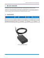
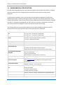
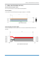
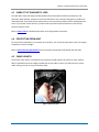
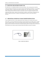
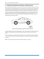
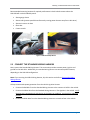
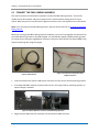
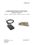
LenderOutlook Device Install Guide Installation Instructions LMU-3XX CalAmp Corporation 1401 N. Rice Avenue, Oxnard, CA 93030 Phone: 805.987.9000 Fax: 805.987.8359 www.calamp.com LMU-7XX LMU-8XX Document: MBUD-0266v1.1 Updated: February 2014 CalAmp | LenderOutlook Device Install Guide CalAmp | LenderOutlook Device Install Guide Copyright © 2014 CalAmp Corporation. All rights reserved. Printed in the United States of America. All trademarks used are properties of their respective owners. Products offered may contain software proprietary to CalAmp or other parties. The offer of these products and services does not include or infer any transfer of ownership. No part of the documentation or information supplied may be divulged to any third party without the express written consent of CalAmp. CalAmp reserves the right to modify the equipment, its specification or this manual without prior notice, in the interest of improving performance, reliability, or servicing. At the time of publication all data is correct for the operation of the equipment at the voltage and/or temperature referenced. Performance data indicates typical values related to the particular product. Product updates may result in differences between the information provided in this manual and the product shipped. We have made every effort to ensure the accuracy of all information contained in this document; however, CalAmp makes no expressed or implied warranty or representation based upon the enclosed information. Revision History: Version # Revision Date Author Details 1.0 01/2014 Product Baseline release 1.1 02/2014 Product Added Ignition Status table. Page ii MBUD-0266v1.1 CalAmp | LenderOutlook Device Install Guide TABLE OF CONTENTS 1 2 REGULATORY INFORMATION .....................................................................................1 1.1 HUMAN EXPOSURE COMPLIANCE STATEMENT .................................................................................. 1 1.2 LMU-XXX HANDLING PRECAUTIONS .............................................................................................. 2 INTRODUCTION ..........................................................................................................4 2.1 3 GUIDE PREREQUISITES .................................................................................................................. 4 LMU-XXX OVERVIEW ..................................................................................................5 3.1 DEVICE MATRIX ........................................................................................................................... 5 3.2 ENVIRONMENTAL SPECIFICATIONS .................................................................................................. 6 3.3 WIRING ...................................................................................................................................... 7 3.3.1 Lmu-3xx ............................................................................................................................ 7 3.3.2 Lmu-7xx and LMU-8xx ...................................................................................................... 7 4 3.4 IGNITION WIRE REQUIREMENTS ..................................................................................................... 8 3.5 SERIAL ADAPTER (DEBUG USE ONLY)................................................................................................ 9 PRE-INSTALLATION CONSIDERATIONS ...................................................................... 10 4.1 VERIFY POWER, GROUND AND IGNITION ........................................................................................ 10 4.2 SIZE AND PLACEMENT OF LMU-XXX ............................................................................................. 10 4.3 VISIBILITY OF DIAGNOSTIC LEDS ................................................................................................... 11 4.4 PROTECTION FROM HEAT ............................................................................................................ 11 4.5 CABLE LENGTH .......................................................................................................................... 11 4.6 MOISTURE AND WEATHER PROTECTION ........................................................................................ 12 4.7 PREVENTING ACCIDENTAL OR UNAUTHORIZED MODIFICATION .......................................................... 12 MBUD-0266v1.1 Page iii CalAmp | LenderOutlook Device Install Guide 5 LMU-XXX INSTALLATION .......................................................................................... 13 5.1 MOUNTING PROCEDURE FOR INTERNAL ANTENNA DEVICES .............................................................. 14 5.2 CONNECT THE STANDARD WIRING HARNESS .................................................................................. 15 5.3 CONNECT THE OBD-II WIRING HARNESS ....................................................................................... 16 5.4 CONNECT OPTIONAL INPUTS ........................................................................................................ 18 5.4.1 Starter Disable ................................................................................................................ 18 5.4.2 Payment Reminder and Notification.............................................................................. 19 5.5 LMU-XXX INSTALLATION VERIFICATION ........................................................................................ 20 5.5.1 Status LEDs ..................................................................................................................... 20 5.6 6 INSTALLATION INSTRUCTIONS FOR EXTERNAL ANTENNA .................................................................... 21 LIMITED WARRANTY ................................................................................................ 21 Page iv MBUD-0266v1.1 CalAmp | LenderOutlook Device Install Guide LIST OF FIGURES Figure 1: CalAmp LMU-XXX Device ........................................................................................................ 5 Figure 2: LMU Serial Adapter ................................................................................................................. 9 Figure 3: LMU-XXX Serial Cable Adapter................................................................................................ 9 Figure 4: Coil Excess Cable ................................................................................................................... 11 Figure 5: Tamper Resistant Materials .................................................................................................. 12 Figure 6: Acceptable (Yellow) and Poor (Red) locations for device placement. .................................. 14 Figure 7: LMU-XXX Example Mount ..................................................................................................... 15 Figure 8: OBD-II Harness ...................................................................................................................... 16 Figure 9: Connect Power and Ground using supplied connectors....................................................... 16 Figure 10: Vehicle OBD-II Port Connector and OBD-II Flange Mounted .............................................. 16 Figure 11: Plugged OBD-II Connectors and Taped Connectors............................................................ 17 Figure 12: Re-mounted OBD-II Port Connector ................................................................................... 17 Figure 13: Optional Starter Disable Relay and Socket ......................................................................... 18 Figure 14: Piezo Buzzer Connection ..................................................................................................... 19 Figure 15: Optional Payment Reminder Wiring ................................................................................... 19 MBUD-0266v1.1 Page v CalAmp | LenderOutlook Device Install Guide 1 REGULATORY INFORMATION 1.1 HUMAN EXPOSURE COMPLIANCE STATEMENT Pursuant to 47 CFR § 24.52 of the FCC Rules and Regulations, personal communications services (PCS) equipment is subject to the radio frequency radiation exposure requirements specified in § 1.1307(b), § 2.1091 and § 2.1093, as appropriate. CalAmp certifies that it has determined that the LMU-XXX complies with the RF hazard requirements applicable to broadband PCS equipment operating under the authority of 47 CFR Part 24, Subpart E of the FCC Rules and Regulations. This determination is dependent upon installation, operation and use of the equipment in accordance with all instructions provided. The LMU-XXX is designed for and intended to be used in fixed and mobile applications. “Fixed” means that the device is physically secured at one location and is not able to be easily moved to another location. “Mobile” means that the device is designed to be used in other than fixed locations and generally in such a way that a separation distance of at least 20 cm is normally maintained between the transmitter’s antenna and the body of the user or nearby persons. The LMU-XXX is not designed for or intended to be used in portable applications (within 20 cm of the body of the user) and such uses are strictly prohibited. To ensure that the LMU-XXX complies with current FCC regulations limiting both maximum RF output power and human exposure to radio frequency radiation, a separation distance of at least 20 cm must be maintained between the unit’s antenna and the body of the user and any nearby persons at all times and in all applications and uses. Additionally, in mobile applications, maximum antenna gain must not exceed 3 dBi. MBUD-0266v1.1 Page 1 CalAmp | LenderOutlook Device Install Guide 1.2 LMU-XXX HANDLING PRECAUTIONS Electrostatic Discharge (ESD) Electrostatic discharge (ESD) is the sudden and momentary electric current that flows between two objects at different electrical potentials caused by direct contact or induced by an electrostatic field. The term is usually used in the electronics and other industries to describe momentary unwanted currents that may cause damage to electronic equipment. ESD Handling Precautions ESD prevention is based on establishing an Electrostatic Protective Area (EPA). The EPA can be a small working station or a large manufacturing area. The main principle of an EPA is that there are no highly charging materials in the vicinity of ESD sensitive electronics, all conductive materials are grounded, workers are grounded, and charge build-up on ESD sensitive electronics is prevented. International standards are used to define typical EPA and can be obtained for example from International Electrotechnical Commission (IEC) or American National Standards Institute (ANSI). This ESD classification of the sub assembly will be defined for the most sensitive component, therefore the following classifications apply: Class 1B – Human Model (< 1 kV) Class M1 – Machine Model (< 100V) When handling the LMU-XXX’s main-board (i.e. sub assembly) by itself or in a partial housing proper ESD precautions should be taken. The handler should be in an ESD safe area and be properly grounded. GPS Ceramic Patch Handling When handling the sub assembly it may be natural to pick it up by sides and make contact with the antenna boards. In an uncontrolled ESD environment, contact with the center pin of ceramic patch antenna can create a path for electrostatic discharge directly to the GPS Module. The GPS Module is very sensitive to ESD and can be damaged and rendered non-functional at low levels of ESD. One should avoid contact with the center pin of the patch during handling. The Factory will be placing a protective layer of Kapton® tape over the patch element to eliminate this ESD path. Packaging Anytime the sub assembly is shipped and it is not fully packaged in its final housing it must be sealed in an ESD safe bag. Page 2 MBUD-0266v1.1 CalAmp | LenderOutlook Device Install Guide Electrical Over-Stress (EOS) The LMU-XXX GPS receiver can be damaged if exposed to an RF level that exceeds its maximum input rating. Such exposure can happen if a nearby source transmits an RF signal at sufficiently high level to cause damage. Storage and Shipping One potential source of EOS is proximity of one LMU-XXX GPS Antenna to another LMU-XXX GSM Antenna. Should one of the units be in a transmit mode, the potential exists for the other unit to become damaged. Therefore, keep any LMU-XXX unit at least four inches apart from any active unit or any other active high power RF transmitter with power greater than 1 Watt. Battery Back-up Devices Properly dispose of the battery in any of the CalAmp products that utilize one. Do not throw used batteries, replaced batteries or units containing a back-up battery into the trash. Consult your local waste management facility for proper disposal instructions. MBUD-0266v1.1 Page 3 CalAmp | LenderOutlook Device Install Guide 2 INTRODUCTION The LMU device is one of the most flexible, economical, mobile-tracking hardware products available. This Install Guide provides an overview of the LMU characteristics, functionality and installation, divided into the following sections: LMU Overview – Provides an overview of the physical and environmental characteristics. Pre-Installation Considerations – Provides guidance and considerations for preparing to install the LMU device. LMU Installation and Verification – Provides guidance for the physical installation of the LMU device in a vehicle to verify the installation is performing adequately. 2.1 GUIDE PREREQUISITES In order to limit the size and scope of this guide, the following assumptions have been made about the reader. You are familiar with GPS concepts and terminology. You have some experience with installing equipment in vehicles. Page 4 MBUD-0266v1.1 CalAmp | LenderOutlook Device Install Guide 3 LMU-XXX OVERVIEW The CalAmp Location and Messaging Unit (LMU-XXX) is a mobile device that resides in private, commercial or government vehicles. The LMU-XXX is a single box enclosure, incorporating a processor, a GPS receiver, a wireless data modem and a vehicle-rated power supply. The device supports inputs and outputs to monitor and react to the vehicular environment and driver actions. 3.1 DEVICE MATRIX Device Available Basic LMU-300 LMU-700 LMU-800 (Internal Antenna) LMU-800 (External Antenna) Q1-2014 Active Active Active CVF-322-23 CVF-710-23 CVF-810-23 CVF-810-33 With Starter Disable CVF-322-24 CVF-710-24 CVF-810-24 CVF-810-34 With SD and Payment Reminder Not available CVF-710-27 CVF-810-27 CVF-810-37 Figure 1: CalAmp LMU-XXX Device MBUD-0266v1.1 Page 5 CalAmp | LenderOutlook Device Install Guide 3.2 ENVIRONMENTAL SPECIFICATIONS The LMU-XXX is designed to operate in environments typically encountered by fleet vehicles, including wide temperature extremes, voltage transients and potential interference from other vehicle equipment. To ensure proper operation in such an environment, the LMU-XXX was subjected to standard tests defined by the Society of Automotive Engineers (SAE). The specific tests included temperature, shock, vibration and EMI/EMC. These tests were performed by independent labs and documented in a detailed test report. In accordance with Appendix A of SAE J1113 Part 1, the Unit is considered a “Functional Status Class B, Performance Region II” system that requires Threat Level 3 Testing. The following shows the environmental conditions the LMU-XXX is designed to operate in and the relevant SAE tests that were performed. No formal altitude tests were conducted. Size Weight 1.8 x 3.0 x 0.78” | 46.5 x 77 x 19.7mm (LMU-3XX) 2.1 x 3.5 x 0.62” | 54 x 89 x 16 mm (LMU-7XX) 2.1 x 3.6 x 0.77” | 53 x 96 x 19 mm (LMU-8XX) 3.5 ounces | 99 grams (LMU-3XX with harness) 2.6 ounces | 74 grams (LMU-7XX without harness) 3.7 ounces | 106 grams (LMU-8XX) Operating Temperature -30° C to +75° C Storage Temperature -40° C to +85° C Humidity 0% to 95% relative humidity, at 50° C non-condensing SAE Test: SAE J1455 Compliant U.S. Military Standards 202G and 810F Compliant Ground vehicle environment with associated shock and vibration SAE Test: SAE J1113 Parts 2, 12, 21 and 41 Compliant FCC Part 15B Compliant Industry Canada Compliant EMC Compliant for a ground vehicle environment 6-32 VDC Less than 70 mA @ 12/24v on active standby (Visit www.calamp.com for datasheets containing specific power consumption.) LMU-3XX, LMU-7XX- Not available LMU-8XX - 200 mAh, 1 hour charge time 50 channel WAAS capable GPS Receiver 2m CEP (with SBAS) -162 dBm Tracking Sensitivity -147dBm Acquisition Sensitivity Shock and Vibration Electromagnetic Compatibility (EMC/EMI) Operating Voltage Range Power Consumption Back-up Battery Option GPS Communications (Comm) LMU-3XX, LMU-7XX, LMU-8XX: GSM/GPRS Bands 850/900/1800/1900 RoHS Compliant Page 6 MBUD-0266v1.1 CalAmp | LenderOutlook Device Install Guide 3.3 WIRING 3.3.1 LMU-3XX The LMU-3XX has 4 22AWG leads for its power and I/O connections. These leads are mapped as follows: Signal Name Wire Description Color Input or Output Usage 1 GND Ground Black Ground – Serial Cable Required 2 VCC Primary Power Input Red Power Required 3 IN-0 Input 0 White Ignition Input Required 4 Out-0 Output 0 Green Output to Relay Optional 3.3.2 LMU-7XX AND LMU-8XX The LMU-7XX and LMU-8XX have 8 22AWG leads for its power and I/O connections. These leads are mapped as follows: Signal Name Wire Description Color Input or Output Usage Ground – Serial Cable Required Primary Power Input Red Power Required IN-0 Input 0 White Ignition Input Required 4 IN-1 Input 1 Blue Input Not used 5 IN-2 Input 2 \ Rx Orange Input \ Serial Rx Not used 6 Out-0 Output 0 Green Output to Starter Relay Optional 7 Out-1 Output 1 Brown Output Not used 8 Out-2 Output 2 \ Tx Yellow Output to PR buzzer Optional 1 GND Ground 2 VCC 3 MBUD-0266v1.1 Black Page 7 CalAmp | LenderOutlook Device Install Guide 3.4 IGNITION WIRE REQUIREMENTS The following table provides a listing of devices and if the White Ignition wire of the P/N 5C896 cable is required. Part Number Type Unit CVF-322-23US1970 CVF-322-24US1970 CVF-710-23US1970 CVF-710-24US1970 CVF-710-27US1970 CVF-710-29US2020 CVF-810-23US1970 CVF-810-24US1970 CVF-810-27US1970 CVF-810-33US1970 CVF-810-34US1970 CVF-810-37US1970 Tracking Starter Disable Tracking Starter Disable SD & Payment Reminder SD & Payment Reminder Tracking Starter Disable SD & Payment Reminder Tracking Starter Disable SD & Payment Reminder How do you tell which device it is? No additional hardware is in the box The box includes a starter relay The box includes a buzzer No additional hardware is in the box The box includes a starter relay The box includes a buzzer No additional hardware is in the box The box includes a starter relay The box includes a buzzer No additional hardware is in the box The box includes a starter relay The box includes a buzzer Is White Ignition Wire connection needed? Attach only if sleep mode is used* Yes Attach only if sleep mode is used* Yes Yes Yes Attach only if sleep mode is used* Yes Yes Attach only if sleep mode is used* Yes Yes * Sleep mode is used to turn the device off for vehicles not in regular use. This mode prevents battery drain while the vehicle is sitting in the dealer lot. Sleep mode is not used after the vehicle is delivered to a customer. Page 8 MBUD-0266v1.1 CalAmp | LenderOutlook Device Install Guide 3.5 SERIAL ADAPTER (DEBUG USE ONLY) LMU Serial Cable (Part Number 133337) This is the LMU standard serial cable used with LMU-XXX products. LMU Serial Adapter It only connects to the LMU-XXX products through an adapter (i.e., the 5C883). Figure 2: LMU Serial Adapter Serial Cable Adapter (Part Number 5C883) The Serial Cable Adapter accessory allows users to connect the standard LMU Serial Cable to the LMU-XXX. Figure 3: LMU-XXX Serial Cable Adapter MBUD-0266v1.1 Page 9 CalAmp | LenderOutlook Device Install Guide 4 PRE-INSTALLATION CONSIDERATIONS Installation can have a major impact on the performance of the LMU-XXX. It is recommended that installers be familiar with the installation of GPS and cellular devices and are comfortable in a vehicle environment. The best way to ensure a trouble-free installation is to consider your options and make appropriate decisions before you start. Be advised that an installation that violates the LMU-XXX Environmental Specifications will void the warranty. The best way to ensure a trouble-free installation is to consider your options and make appropriate decisions before you start. Review the vehicle and determine the best install approach for the LMU-XXX for the following purposes: Ongoing monitoring and maintenance of LMU-XXX Accidental or intentional alteration of the equipment or cable connections Prior to beginning the installation process, verify that you have all the required LMU-XXX components: The LMU-XXX device Input and output cables (optional) 4.1 VERIFY POWER, GROUND AND IGNITION Check each source (power, ground and ignition) to ensure that the proper signaling exists. This is typically accomplished with a multi-meter. 4.2 SIZE AND PLACEMENT OF LMU-XXX When planning device installation, take into account the LMU-XXX dimensions. Typically, the LMU-XXX is installed under the vehicle dashboard. Verify that you can access the device post-installation in the event you need to verify LED status lights or access the unit. Refer to Environmental Specifications for the exact measurements and specifications of the LMU-XXX. Verify that the LMU-XXX fits in selected location before drilling any holes or running cable. Ensure that the cable running to the LMU-XXX will not be bent or constricted. Damage to the cable may impede the LMU-XXX performance. Wrap cable in protective plastic shielding if necessary. Verify that the installation point does not violate any of the LMU-XXX’s environmental specifications. Improper installation of the LMU-XXX may void the warranty. Page 10 MBUD-0266v1.1 CalAmp | LenderOutlook Device Install Guide 4.3 VISIBILITY OF DIAGNOSTIC LEDS The LMU-XXX’s status LED lights provide valuable information about the device performance and operation. When feasible, attempt to install the LMU-XXX in such a way that the lights are visible with reasonable ease. If you observe poor performance, you may need to read the LEDs to troubleshoot the issue. If you cannot resolve the issue, you will need to provide the LED information to the CalAmp Customer Support Team. Refer to Status LEDs for detailed information on the light patterns and status. 4.4 PROTECTION FROM HEAT Do not place the LMU-XXX in an unusually warm location, such as directly near heater vents, hot engine components or direct sunlight. Refer to Environmental Specifications for the maximum temperature tolerated by the LMU-XXX. 4.5 CABLE LENGTH The harness cable, which is provided for connecting to the LMU-XXX to the vehicle or other auxiliary device, should be used at the length provided. Do not cut cables. Instead, coil and secure any excess cable, making sure not to crimp or bend the cable. Figure 4: Coil Excess Cable MBUD-0266v1.1 Page 11 CalAmp | LenderOutlook Device Install Guide 4.6 MOISTURE AND WEATHER PROTECTION The LMU-XXX is not a weatherproof device and must be kept dry. The mounting location should be inside the passenger compartment of the vehicle safe from physical damage and where it is not exposed to moisture or water. In a typical inside-vehicle installation, this is not a common concern; however, avoid installing the device below the vehicle’s cup holders or where rain might easily splash into the compartment when a door is opened. If the LMU-XXX is installed in a vehicle with a cab exposed to the weather, additional protection is required to avoid damage to the device, which could void the warranty. 4.7 PREVENTING ACCIDENTAL OR UNAUTHORIZED MODIFICATION If you anticipate that drivers or others might tamper with the devices once installed, take steps to ensure that it is not easy to disconnect the wiring or remove the device from its power source. A tamper resistant installation couples a zip-tie secured around the device with a tamper seal applied to protect against potential interference and to deter intentional tampering. When the tamper seal is removed, the seal self-destructs to indicate removal and leaves behind a dot-pattern residue on the device. Figure 5: Tamper Resistant Materials Page 12 MBUD-0266v1.1 CalAmp | LenderOutlook Device Install Guide 5 LMU-XXX INSTALLATION Installing the LMU-XXX is not difficult, but you must consider the variables involved, such as the vehicle type and location of existing equipment. Installation time can vary depending upon the installer’s experience and the vehicle design. The average time for installation is approximately 45 minutes. A single individual can perform most installation operations. To install the LMU-XXX: 1. Select location for mounting the device and install it. • Assess cable routes while considering placement to avoid exposure to damage. 2. Install the power, ignition and ground connections. 3. Install optional I/O connections. 4. Secure all cables to rigid mounts with cable restraints. 5. Verify operation of the LMU-XXX. MBUD-0266v1.1 Page 13 CalAmp | LenderOutlook Device Install Guide 5.1 MOUNTING PROCEDURE FOR INTERNAL ANTENNA DEVICES When determining mounting location, the primary consideration is GPS satellite visibility. LMU-XXX have internal antennas for both GPS and Cellular. The GPS antenna is located directly under the product label side of the device. The required install orientation of the LMU-XXX is a horizontal mount, label side up. Attach the LMU-XXX to the solid body of the vehicle not to plastic panels. Additionally, verify that any metal is not covering or obstructing the LMU-XXX, allowing the device to have a clear sight with GPS satellites. A typical location is under the vehicle dashboard close to the front windshield. For a stealth installation, remove interior trim or molding to expose available space, and then replace the trim or molding when the LMU-XXX is installed. Figure 6: Acceptable (Yellow) and Poor (Red) locations for device placement. For proper mounting, ensure the mounting location is clean. Use a damp towel or alcohol clean wipes, if necessary. Peel off adhesive and mount the LMU-XXX. If required, use a zip-tie to ensure a secure mount. Plan to route the wires to minimize exposure to damage. If wires are exposed, wrap them with plastic protective cable wrap common to automotive applications. All wiring must be secured to complete the installation. Note: It is important that you do not mount the LMU-XXX above or near airbags. Page 14 MBUD-0266v1.1 CalAmp | LenderOutlook Device Install Guide Recommended mounting locations for optimal performance include in-dash mounts where the LMU-XXX will not be shielded by metal: • Above gauge cluster • Above radio (prevent possible interference by routing power harness away from radio wires) • Above air vents or air duct • Glove box • Center console Figure 7: LMU-XXX Example Mount 5.2 CONNECT THE STANDARD WIRING HARNESS Next, connect the Standard Wiring Harness. This connection provides constant power, ignition and ground for the LMU-XXX. Additionally, the standard wiring harness can connect optional features, depending on the LMU-XXX configuration. Note: If you are using the OBD-II Wiring Harness, skip this section and refer to Connect the OBD-II Wiring Harness. CalAmp recommends power generation from the vehicle’s Ignition Harness. • Connect the Red Wire from the Standard Wiring Harness to the constant +12VDC in the vehicle. • Connect the White Wire from the Standard Wiring Harness to True Ignition in the vehicle. Verify that the wire is powered only with the key in the engine on condition, not the ACC or radio key position. • Connect the Black Wire from the Standard Wiring Harness to a metal surface in the vehicle. MBUD-0266v1.1 Page 15 CalAmp | LenderOutlook Device Install Guide 5.3 CONNECT THE OBD-II WIRING HARNESS This section contains the information required to connect the OBD-II Wiring Harness. This harness enables you to obtain power and ground signal from the vehicle without splicing wires from your vehicle. Note that you must still connect the ignition sense wire to the true ignition wire on the vehicle. Note: If you are using the Standard Wiring Harness, skip this section and refer to Connect the Standard Wiring Harness. Before you can begin the OBD-II Wiring Harness installation, you must crimp together connections from your LMU-XXX wiring harness to the OBD-II pigtail. Join the Red Wire (power) and Black Wire (ground) from each harness using the supplied butt connectors. Note that some vehicles that feature OBD-II may require hard wiring due to signal strength. Figure 8: OBD-II Harness Figure 9: Connect Power and Ground using supplied connectors 1. Locate and remove the vehicle’s OBD-II port connector from the current vehicle mounting position. • If the LMU-XXX OBD-II harness connector does not fit in the original factory mounting position, an optional flange is available. Figure 10: Vehicle OBD-II Port Connector and OBD-II Flange Mounted 2. Plug the Device OBD-II harness connector into the vehicle’s OBDII connector. Page 16 MBUD-0266v1.1 CalAmp | LenderOutlook Device Install Guide 3. Secure the LMU-XXX OBD-II harness connector and the OBD-II connector together with tape to prevent loose connections that may occur from normal vehicle operation vibration. Figure 11: Plugged OBD-II Connectors and Taped Connectors 4. Re-mount the LMU-XXX OBD-II harness connector in the vehicle’s original location. 5. Important: The OBD-II port provides device power, but to obtain ignition condition, you must connect the White Wire from the Standard Wiring Harness to True Ignition in the vehicle. • Connect the White Wire from the Standard Wiring Harness to True Ignition in the vehicle. Verify that the wire is powered only with the key in the engine on condition, not the ACC or radio key position. Figure 12: Re-mounted OBD-II Port Connector MBUD-0266v1.1 Page 17 CalAmp | LenderOutlook Device Install Guide 5.4 CONNECT OPTIONAL INPUTS The options available for the LMU-XXX devices include starter disable and payment reminder. Note: When connecting the I/O, you may be required to provide additional length of 22AWG wire, depending on where the I/O connection is located compared to the Power/Ign/Ground connections. 5.4.1 STARTER DISABLE The Starter Disable feature requires true ignition power in cases where the vehicle’s starter wire does not supply the necessary voltage to operate the relay (+12VDC when the key switch is in the ON position, during ignition on and when the vehicle is in operation). Some vehicles may require cutting the White jumper wire from the Blue wire. If necessary, the White wire must be connected to the vehicle’s ignition source. Note: Some vehicles may not have a starter wire located at the ignition harness. If you are installing starter interrupt in one of these vehicles, CalAmp recommends an expert installer perform the installation. Alternatively, request from your authorized CalAmp representative the plug-in Starter Interrupt Module (SIM) device. This device is safe and easy to use and replaces the starter interrupt relay and socket. Note that the starter interrupt module cannot be used on a vehicle with a starter wire located at the ignition harness. 1. Locate and cut the Starter Wire in the vehicle’s ignition harness. 2. Connect the Red Wire from the disable relay to Ignition Switch side of the cut Starter Wire. • Once cut, this wire will show voltage during cranking. 3. Connect the Blue Wire from the disable relay to the Solenoid side of the cut Starter Wire. 4. Using a butt connector, crimp the Green Wire from the Starter disable relay and the Green Wire from the LMU-XXX wire harness together. • The White jumper wire from relay connector is used to supply the relay with 12Volt during cranking. Figure 13: Optional Starter Disable Relay and Socket Page 18 MBUD-0266v1.1 CalAmp | LenderOutlook Device Install Guide 5.4.2 PAYMENT REMINDER AND NOTIFICATION The LMU-7XX and LMU-8XX use the optional Output #2 to send a 30 second negative pulse through the Yellow wire of the LMU-XXX wiring harness to the Piezo Buzzer. Figure 14: Piezo Buzzer Connection 1. Connect the Red Wire from the Piezo Buzzer to White Ignition Power wire. The White ignition wire must also be connected to the vehicle ignition wire. An additional length of 22AWG wire may be needed. 2. Connect the Black Wire from the Piezo Buzzer to the Yellow Output Wire from the LMU-XXX wiring harness. Figure 15: Optional Payment Reminder Wiring MBUD-0266v1.1 Page 19 CalAmp | LenderOutlook Device Install Guide 5.5 LMU-XXX INSTALLATION VERIFICATION Installers should verify that the LMU-XXX GPS and communication functions are working properly before departing the installation site. Installation is complete and successful when you have tested the device. Using LenderOutlook’s mobile app, MobileInstallTM, you can install the vehicle in LenderOutlook and verify device installation from your mobile device. MobileInstall can be downloaded from the Chrome Play store and is free. 5.5.1 STATUS LEDS The LMU-XXX is equipped with two status LEDs – one for GPS and one for Comm (wireless network status). The LEDs use the following blink patterns to indicate service. Verify that the GPS receiver has acquired satellite communication to obtain your GPS position by verifying the GPS status LED (Green). Next, verify that the LMU-XXX has established a 2-way connection with the communication server via the wireless network by checking the GSM/GPRS cellular status LED (Orange). Orange LED Status GSM/GPRS Cellular Communications Green LED Status GPS Communications Blinking – LMU-XXX is powered, searching for wireless signal Blinking – GPS on, searching for satellite signal Patterned Blinking – Signal acquired, LMU-XXX trying to establish connection to communication server Solid – 2-way communication link with the communication Solid – GPS lock established server is established Page 20 MBUD-0266v1.1 CalAmp | LenderOutlook Device Install Guide 5.6 INSTALLATION INSTRUCTIONS FOR EXTERNAL ANTENNA Only the LMU-8xx device supports an external antenna. If you have purchased one of the devices with a part number CVF-810-33, -34 or -37 you should have received p/n IV1353-QB-02 SMA/SMC 3M Quadband cell antenna with your kit. This antenna connects to the GPS and cellular SMx ports on the device. The device should be installed according to the instructions regarding internal antenna devices, however the external antenna allows location of devices in obscure or hard to reach locations that may prevent adequate GPS or cellular reception. The antenna provided is designed to stick on glass or plastic and can then be mounted under the dash or other location suitable for GPS and Cellular reception. 6 LIMITED WARRANTY Covering the Physical Media and Printed Materials: CalAmp warrants to you, the original licensee, that the media on which the Software is recorded are free from defects in materials and workmanship under normal use and service FOR A PERIOD OF NINETY (90) DAYS FROM THE DATE OF DEVELOPER LICENSE PURCHASE. CalAmp’s entire liability and your exclusive remedy as to defective media, Documentation or Related Material(s) shall be replacement of the media, Documentation or Related Material(s) by CalAmp. Each defective item, along with proof of license purchase and date, must be sent in a traceable manner to: CalAmp DataCom Inc., 1401 North Rice Ave. Oxnard, CA 93030. Disclaimer Regarding the Software, Documentations and Related Materials: THE SOFTWARE, DOCUMENTATION AND RELATED MATERIALS ARE PROVIDED “AS IS.” EXCEPT AS MAY OTHERWISE BE EXPRESSLY SET FORTH HEREIN, CALAMP MAKES NO REPRESENTATIONS OR WARRANTIES, EXPRESS OR IMPLIED, WITH RESPECT TO THE SOFTWARE, DOCUMENTATION OR RELATED MATERIALS INCLUDING BY WAY OF EXAMPLE, AND NOT LIMITATION, THE IMPLIED WARRANTIES OF MERCHANTABILITY AND FITNESS FOR A PARTICULAR PURPOSE. BY WAY OF FURTHER EXAMPLE AND NOT LIMITATION, CALAMP MAKES NO REPRESENTATIONS OR WARRANTIES, EXPRESS OR IMPLIED, WITH RESPECT TO THE ACCURACY, RELIABILITY OR COMPLETENESS OF THE DOCUMENTATION OR THE RELATED MATERIALS. THE ENTIRE RISK AS TO THE USE OF THE SOFTWARE, DOCUMENTATION AND RELATED MATERIALS IS ASSUMED BY YOU. IN NO EVENT SHALL CALAMP BE LIABLE TO YOU OR ANY OTHER PERSON, REGARDLESS OF THE CAUSE, FOR THE EFFECTIVENESS OR ACCURACY OF THE SOFTWARE, DOCUMENTATION OR RELATED MATERIALS OR FOR ANY SPECIAL, INDIRECT, INCIDENTAL OR CONSEQUENTIAL DAMAGES ARISING FROM OR OCCASIONED BY YOUR USE OF THE SOFTWARE, DOCUMENTATION OR RELATED MATERIALS, EVEN IF ADVISED OF THE POSSIBILITY OF SUCH DAMAGES. IN THE EVENT THE FOREGOING IS FOUND BY A COURT OF COMPETENT JURISDICTION TO BE INEFFECTIVE, YOU HEREBY AGREE THAT CALAMP’S MAXIMUM LIABILITY FOR ANY CLAIM ARISING IN CONNECTION WITH THE SOFTWARE, DOCUMENTATION AND/OR RELATED MATERIALS (WHETHER IN CONTRACT, TORT, INCLUDING NEGLIGENCE, PRODUCT LIABILITY OR OTHERWISE) SHALL NOT EXCEED MBUD-0266v1.1 Page 21 CalAmp | LenderOutlook Device Install Guide THE LICENSE FEES PAID BY YOU WITH RESPECT TO THE SOFTWARE, DOCUMENTATION AND/OR RELATED MATERIALS AT ISSUE. SOME STATES DO NOT ALLOW THE LIMITATION OR EXCLUSION OF INCIDENTAL OR CONSEQUENTIAL DAMAGES, SO THE FOREGOING PROVISION, WITH RESPECT TO EXCLUDING OR LIMITING SUCH DAMAGES, MAY NOT APPLY TO YOU. Acknowledgement: You acknowledge that you have read this LIMITED WARRANTY, understand it and agree to be bound by its terms and conditions. You also agree that: (1) No oral or written information or advice given by CalAmp, its dealers, distributors, agents or employees shall in any way increase the scope of this Limited Warranty and you may not rely on any such information or advice; (2) Unless a written governing agreement signed by you and CalAmp exists, this License Agreement is the complete and exclusive statement of agreement between CalAmp and you regarding the licensing of the Software, Documentation and Related Materials and supersedes all proposals, oral or written, and any other communications you may have had prior to purchasing your license; (3) Except for the price and delivery terms agreed upon by both parties, the terms and conditions of this License Agreement shall supersede those set forth in any purchase order where the purchase order conflicts or is inconsistent with or adds to the terms and conditions of this License and those superseded purchase order terms and conditions shall be null and void; (4) You agree to assure that copies of this License Agreement are distributed, read and agreed to by each Developer using the Software and/or Documentation. Governing Law: This Agreement shall be governed by the laws of the State of California, United States, excluding its conflicts of law principles and excluding the United Nations Convention on Contracts for the International Sale of Goods. You agree to exclusive jurisdiction of California State federal and state courts, Ventura County, for resolution of any dispute related to this Agreement. U.S. Government Protected Rights: The Software Documentation and Related Materials are provided with RESTRICTED RIGHTS. Use, duplication or disclosure by the Government is subject to restrictions as set forth in subparagraph ©(1)(ii) of the Rights in Technical Data and Computer Software clause at DFARS 252.227-7013 or subparagraphs ©(1) and (2) of the Commercial Computer Software-Restricted Rights at 48 CFR 52.227-19, as applicable. Manufacturer is CalAmp DataCom Inc., 1401 North Rice Ave. Oxnard, CA 93030. Rights are reserved under copyright laws of the United States with respect to unpublished portions of the Software. Page 22 MBUD-0266v1.1