1
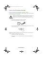
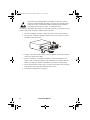
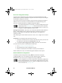
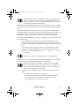
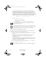
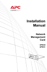
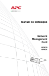
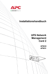
DMP IM 990-3404.book Page i Monday, March 11, 2013 9:05 AM
Installation Manual
UPS Network
Management
Card 2
AP9630, AP9631
DMP IM 990-3404.book Page ii Monday, March 11, 2013 9:05 AM
This manual is available in English on the APC Web site (www.apc.com).
Dieses Handbuch ist in Deutsch auf der APC Webseite (www.apc.com)
verfügbar.
Este manual está disponible en español en la página web de APC
(www.apc.com).
Ce manuel est disponible en français sur le site internet d’APC (www.apc.com).
Questo manuale è disponibile in italiano sul sito web di APC (www.apc.com).
Este manual está disponível em português no site da APC (www.apc.com).
Данное руководство на русском языке доступно на сайте APC
(www.apc.com )
本マニュアルの日本語版は APC ウェブサイト (www.apc.com)
からダウンロードできます。
APC 웹싸이트 (www.apc.com) 에 한국어 매뉴얼 있습니다 .
在 APC 公司的网站上 (www.apc.com) 有本手册的中文版。
This manual is available in English on the enclosed CD.
Dieses Handbuch ist in Deutsch auf der beiliegenden CD-ROM verfügbar.
Este manual está disponible en español en el CD-ROM adjunto.
Ce manuel est disponible en français sur le CD-ROM ci-inclus.
Questo manuale è disponibile in italiano nel CD-ROM allegato.
Este manual está disponível em português no CD fornecido.
Данное руководство на русском языке имеется на прилагаемом
компакт-диске.
本マニュアルの日本語版は同梱の CD-ROM からご覧になれます。
동봉된 CD 안에 한국어 매뉴얼이 있습니다 .
您可以从包含的 CD 上获得本手册的中文版本。
DMP IM 990-3404.book Page i Monday, March 11, 2013 9:05 AM
Contents
How to Avoid Equipment Damage . . . . . . . . . . . . . . . . . . . . . . . . 1
Disconnect power for Smart-UPS or expansion chassis 1
Preliminary Information . . . . . . . . . . . . . . . . . . . . . . . . . . . . . . . . . 3
Features 3
Related documents 3
Inventory 3
Disclaimer 4
Language Packs 4
Installation in a UPS . . . . . . . . . . . . . . . . . . . . . . . . . . . . . . . . . . . . 5
How to install the card for different UPS models 5
Step 1: Turn off power (Smart-UPS) 5
Step 2: Install the Network Management Card 5
Step 3: Restore power to the card slot 6
Step 4: Configure the Network Management Card 6
Expansion/Triple Chassis Installation . . . . . . . . . . . . . . . . . . . . . 7
When to use an Expansion Chassis 7
When to use the AC adapter (AP9505) 7
Step 1: Disconnect the chassis from all power 7
Step 2: Install the Network Management Card 7
Quick Configuration . . . . . . . . . . . . . . . . . . . . . . . . . . . . . . . . . . . . 9
Overview 9
TCP/IP configuration methods 9
Device IP Configuration Utility 10
DHCP and BOOTP configuration 10
Local access to the command line interface 12
Remote access to the command line interface 13
Command line interface 14
.INI file utility 14
How to Recover from a Lost Password . . . . . . . . . . . . . . . . . . . 15
Installation Manual
i
DMP IM 990-3404.book Page ii Monday, March 11, 2013 9:05 AM
How to Access a Configured Network Management Card . . . . 17
Overview 17
Web interface 17
Telnet and SSH 18
Simple Network Management Protocol (SNMP) 18
FTP and SCP 19
Manage the security of your system 19
How to Install Multiple Management Cards . . . . . . . . . . . . . . . . 21
Overview 21
Before you start 21
Two models of expansion chassis 21
Installing cards in an expansion chassis 22
Installing cards in an expansion chassis set up serially 22
Installing cards in a Symmetra UPS 22
Specifications . . . . . . . . . . . . . . . . . . . . . . . . . . . . . . . . . . . . . . . . 25
ii
Installation Manual
DMP IM 990-3404.book Page 1 Monday, March 11, 2013 9:05 AM
How to Avoid Equipment Damage
Disconnect power for Smart-UPS or expansion chassis
You do not need to turn off a Symmetra® or MGE® Galaxy® UPS to install the UPS
Network Management Card 2 (NMC).
Damage to the UPS or NMC can result if you do not remove all AC and
DC power from a Smart-UPS®, an Expansion Chassis, or a Triple
Expansion Chassis before you install the Network Management Card.
Smart-UPS.
1. Turn off the equipment that connects to the UPS.
2. Disconnect the UPS from its AC input source.
3. Press the OFF button on the UPS for approximately five seconds to turn off
the DC (battery) power.
Expansion chassis. Make sure that the Expansion Chassis or Triple Expansion
Chassis is disconnected from any power source:
1. Disconnect the chassis cable from the UPS.
2. If the chassis uses an AC adapter (AP9505), disconnect that adapter from
the chassis.
Installation Manual
1
DMP IM 990-3404.book Page 2 Monday, March 11, 2013 9:05 AM
2
Installation Manual
DMP IM 990-3404.book Page 3 Monday, March 11, 2013 9:05 AM
Preliminary Information
Features
The Schneider Electric UPS Network Management Cards 2 (AP9630
and AP9631) discussed in this document are Web-based, IPv6 Ready
products.
Related documents
The Network Management Card Utility CD contains the following documentation:
•
UPS Network Management Card 2 User’s Guide
•
Network Management Card Upgrade Utilities
•
Security Handbook
•
PowerNet® Management Information Base (MIB) Reference Guide
Inventory
The Network Management Card package includes the following items:
•
This Installation Manual
•
UPS Network Management Card 2
•
UPS Network Management Card 2 Utility CD
•
Serial configuration cable (940-0299)
•
Temperature sensor (AP9335T)—AP9631 Network Management Card only
•
Network Management Card quality assurance test slip
•
Declaration of Conformity
•
Warranty registration form
The quality assurance test slip contains the MAC address that you may
need when performing the procedures in “Device IP Configuration
Utility” on page 10. You can also find the MAC address on the back of
your UPS.
Installation Manual
3
DMP IM 990-3404.book Page 4 Monday, March 11, 2013 9:05 AM
Disclaimer
Schneider Electric is not responsible for damage sustained during reshipment of this
product.
The Network Management Card (NMC) is sensitive to static
electricity. When handling the NMC, touch only the end plate while
using one or more of these electrostatic-discharge devices (ESDs):
wrist straps, heel straps, toe straps, or conductive shoes.
Please recycle
The shipping materials are recyclable. Save them for later use, or
dispose of them appropriately.
Management products, including the NMC, contain removable, lithium
coin-cell batteries. When discarding these batteries, you must follow
local rules for recycling.
Language Packs
If the language you want to use with the NMC Web interface is not
available, you should download a language pack. See “Adding and
Changing Language Packs” in the User’s Guide. (Language packs are
not available for all UPS devices).
4
Installation Manual
DMP IM 990-3404.book Page 5 Monday, March 11, 2013 9:05 AM
Installation in a UPS
How to install the card for different UPS models
You can install the UPS Network Management Card (NMC) in a card slot in a
Smart-UPS, Symmetra UPS, Galaxy 300, Galaxy 3500, or Galaxy 7000.
You cannot install this NMC in a Symmetra PX 250 or Symmetra PX
500 UPS.
In a Symmetra UPS that uses more than one management product, you must install
the management products in the correct order for them to operate properly.
See “How to Install Multiple Management Cards” on page 21.
You do not need to turn off power to install a Symmetra UPS.
Step 1: Turn off power (Smart-UPS)
Damage to the UPS or the NMC can result if you do not remove all AC
and DC power from a Smart-UPS.
Step 2: Install the Network Management Card
The NMC is sensitive to static electricity. When handling the NMC,
touch only the end plate while using one or more of these electrostaticdischarge devices (ESDs): wrist straps, heel straps, toe straps, or
conductive shoes.
For the location of the UPS card slot, see the UPS documentation.
1. Locate the UPS card slot.
2. Use the same screws that hold the slot cover in place to secure the NMC in
the UPS card slot.
Installation Manual
5
DMP IM 990-3404.book Page 6 Monday, March 11, 2013 9:05 AM
3. Connect a network interface cable to the 10/100Base-T network connector
on the NMC.
60a
mph 04
Step 3: Restore power to the card slot
To restore power to the card slot and energize the NMC, reconnect the UPS to its
input power source and then turn on the UPS
Step 4: Configure the Network Management Card
See “Quick Configuration” on page 9.
6
Installation Manual
DMP IM 990-3404.book Page 7 Monday, March 11, 2013 9:05 AM
Expansion/Triple Chassis Installation
When to use an Expansion Chassis
Use an Expansion Chassis or a Triple Expansion Chassis if the UPS has no card slot
available.
When you install the UPS Network Management Card (NMC) in the chassis, the
NMC communicates with the UPS through the cable connection between the chassis
and the UPS.
When to use the AC adapter (AP9505)
Use the optional AC adapter with a chassis under the following circumstances:
•
To connect the chassis to an independent AC input so that the NMC can
continue to operate if the UPS is turned off or not operating.
•
To provide the management products mounted in a Triple Expansion
Chassis with more current than the UPS can provide through the UPS-tochassis cable.
A Smart-UPS or Symmetra UPS can provide up to 200 mA.
For information about the current requirements for management
products, see “How to Install Multiple Management Cards” on
page 21.
Step 1: Disconnect the chassis from all power
Make sure that the Expansion Chassis or Triple Expansion Chassis is disconnected
from any power source:
1. Disconnect the chassis cable from the UPS.
2. If the chassis uses an AC adapter (AP9505), disconnect that adapter from
the chassis.
Step 2: Install the Network Management Card
If the UPS uses multiple management products, you must install them in the correct
order for them to operate properly.
See “How to Install Multiple Management Cards” on page 21.
Installation Manual
7
DMP IM 990-3404.book Page 8 Monday, March 11, 2013 9:05 AM
The UPS Network Management Card (NMC) is sensitive to static
electricity. When handling the NMC, touch only the end plate while
using one or more of these electrostatic-discharge devices (ESDs):
wrist straps, heel straps, toe straps, or conductive shoes.
If a cable is connected to the serial port at the UPS or chassis, stop the APC service
that uses that serial connection, and disconnect the cable.
1. If you are installing a chassis, connect the chassis to the UPS serial port.
mph0459a
2. Use the same screws that hold the expansion slot cover in place to secure
the NMC in the chassis slot.
3. Connect a network interface cable to the 10/100Base-T network connector
on the front panel of the NMC.
4. If you are using the AC Adapter (AP9505), connect the adapter to the
chassis. Then connect the adapter to an independent AC input so that the
NMC can continue to operate if the UPS is turned off or not operating.
5. If you disconnected a cable in step 1, reconnect that cable to the serial port
at the chassis, and restart the associated APC service.
6. See “Quick Configuration” on page 9.
8
Installation Manual
DMP IM 990-3404.book Page 9 Monday, March 11, 2013 9:05 AM
Quick Configuration
Overview
Disregard the procedures described in this chapter if you have
StruxureWare Central as part of your system. See the documentation for
your StruxureWare device for more information.
You must configure the following TCP/IP settings before the UPS Network
Management Card (NMC) can operate on a network:
•
IP address of the NMC
•
Subnet mask
•
Default gateway
If a default gateway is unavailable, use the IP address of a computer that
is located on the same subnet as the NMC and that is usually running.
The NMC uses the default gateway to test the network when traffic is
very light.
Do not use the loopback address (127.0.0.1) as the default gateway
address for the NMC. It disables the card and requires you to reset TCP/
IP settings to their defaults using a local serial login.
See “Watchdog Features” in the “Introduction” of the NMC User’s
Guide for more information about the watchdog role of the default
gateway.
TCP/IP configuration methods
Use one of the following methods to define the TCP/IP settings needed by the
Network Management Card for IPv4:
•
“Device IP Configuration Utility” on page 10
•
“How to Recover from a Lost Password” on page 15
•
Networked computer:
–
“Local access to the command line interface” on page 12
–
“Remote access to the command line interface” on page 13
Installation Manual
9
DMP IM 990-3404.book Page 10 Monday, March 11, 2013 9:05 AM
Device IP Configuration Utility
The Device IP Configuration Utility can discover Network Management Cards
(NMC) that do not have an IP address assigned. Once discovered, you can configure
the IP address settings for the cards.
You can also search for devices already on the network by entering an IP range to
define the search. The Utility scans the IP addresses in the defined range and
discovers cards that already have a DHCP-assigned IP address.
For detailed information on the Utility, see the Knowledge Base on the
support page of the www.apc.com website and search for FA156064
(the ID of the relevant article). To use the DHCP Option 12 (AOS 5.1.5
or higher), see Knowledge Base ID FA156110.
System requirements. The Utility runs on Microsoft Windows 2000, Windows
Server® 2003, Windows Server 2012 and on both 32- and 64-bit versions of
Windows XP, Windows Vista, Windows 2008, Windows 7 and Windows 8
operating systems.
This utility supports cards that have firmware version 3.0.x or higher and is for IPv4
only.
Installation. To install the Utility from the Utility CD:
1. If autorun is enabled, the user interface of the CD starts when you insert the
CD. Otherwise, open the file contents.htm on the CD.
2. Click Device IP Configuration Utility and follow the instructions.
To install the Utility from a downloaded executable file:
1. Go to www.apc.com/tools/download.
2. Download the Device IP Configuration Utility.
3. Run the executable file in the folder to which you downloaded it.
When installed, the Utility is available through the Windows menu options.
DHCP and BOOTP configuration
The default TCP/IP configuration setting, DHCP, assumes that a properly
configured DHCP server is available to provide TCP/IP settings to Network
Management Cards. You can also configure the setting for BOOTP.
A user configuration (.ini) file can function as a BOOTP or DHCP boot
file. For more information, see the TCP/IP configuration section of the
Network Management Card User’s Guide, available from the Utility CD
or the APC Web site, www.apc.com.
10
Installation Manual
DMP IM 990-3404.book Page 11 Monday, March 11, 2013 9:05 AM
If neither of these servers is available, see “Device IP Configuration
Utility” on page 10, “Local access to the command line interface” on
page 12, or “Remote access to the command line interface” on page 13
to configure the needed TCP/IP settings.
BOOTP. For the Network Management Card to use a BOOTP server to configure
its TCP/IP settings, it must find a properly configured RFC951-compliant BOOTP
server.
In the BOOTPTAB file of the BOOTP server, enter the Network Management
Card’s MAC address, IP address, subnet mask, and default gateway, and, optionally,
a bootup file name. Look for the MAC address on the bottom of the Network
Management Card or on the Quality Assurance slip included in the package.
When the Network Management Card reboots, the BOOTP server provides it with
the TCP/IP settings.
•
If you specified a bootup file name, the Network Management Card
attempts to transfer that file from the BOOTP server using TFTP or FTP.
The Network Management Card assumes all settings specified in the bootup
file.
•
If you did not specify a bootup file name, you can configure the other
settings of the Network Management Card remotely through its Web
interface or command line interface; the user name and password are both
apc, by default.
To create a bootup file, see your BOOTP server documentation.
DHCP. You can use an RFC2131/RFC2132-compliant DHCP server to configure
the TCP/IP settings for the Network Management Card (NMC).
This section summarizes the NMC’s communication with a DHCP
server. For more detail about how a DHCP server can configure the
network settings for a Network Management Card, see the NMC User’s
Guide on the Utility CD or on the website.
1. The NMC sends out a DHCP request that uses the following to identify
itself:
–
A Vendor Class Identifier (APC by default)
–
A Client Identifier (by default, the MAC address of the NMC)
–
A User Class Identifier (by default, the identification of the
application firmware installed on the NMC)
Installation Manual
11
DMP IM 990-3404.book Page 12 Monday, March 11, 2013 9:05 AM
2. A properly configured DHCP server responds with a DHCP offer that
includes all the settings that the NMC needs for network communication.
The DHCP offer also includes the Vendor Specific Information option
(DHCP option 43). The NMC can be configured to ignore DHCP offers that
do not encapsulate the APC cookie in DHCP option 43 using the following
hexadecimal format. (The card does not require this cookie by default).
Option 43 = 01 04 31 41 50 43
where
–
the first byte (01) is the code
–
the second byte (04) is the length
–
the remaining bytes (31 41 50 43) are the APC cookie.
See your DHCP server documentation to add code to the Vendor
Specific Information option.
The NMC Web interface has options to utilize vendor-specific data to
require the DHCP server to provide an “APC” cookie which will supply
information to the NMC. See the User’s Guide for information.
Local access to the command line interface
You can use a computer connected to the serial port on the front of the Network
Management Card to access the command line interface.
1. Select a serial port at the local computer, and disable any service that uses
that port.
2. Use the provided serial cable (part number 940-0299) to connect the
selected port to the serial port on the front panel of the Network
Management Card.
3. Run a terminal program (such as HyperTerminal, TeraTerm, PuTTY) and
configure the selected port for 9600 bps, 8 data bits, no parity, 1 stop bit,
and no flow control. Save the changes.
4. Press ENTER, repeatedly if necessary, to display the User Name prompt.
5. Use apc for the user name and password.
See “Command line interface” on page 14 to finish the configuration.
12
Installation Manual
DMP IM 990-3404.book Page 13 Monday, March 11, 2013 9:05 AM
Remote access to the command line interface
From any computer on the same network as the Network Management Card, you
can use ARP and Ping to assign an IP address to the Network Management Card,
and then use Telnet to access its command line interface and configure the other
TCP/IP settings.
After the Network Management Card has its IP address configured, you
can use Telnet, without first using ARP and Ping, to access that Network
Management Card.
1. Use the MAC address of the Network Management Card in the ARP
command to define the IP address.
Note: Look for the MAC address on the bottom of the Network
Management Card or on the Quality Assurance slip included in the package.
For example, to define 156.205.14.141 as the IP address of a Network
Management Card with 00 c0 b7 63 9f 67 as its MAC address, use one of
the following commands:
–
Windows command format:
arp -s 156.205.14.141 00-c0-b7-63-9f-67
–
LINUX command format:
arp -s 156.205.14.141 00:c0:b7:63:9f:67
2. Use Ping with a size of 113 bytes to assign the IP address defined by the
ARP command. For the IP address defined in step 1, use one of the
following commands:
–
Windows command format:
ping 156.205.14.141 -l 113
–
LINUX command format:
ping 156.205.14.141 -s 113
3. Use Telnet to access the Network Management Card at its newly assigned
IP address. For example:
telnet 156.205.14.141
4. Use apc for both user name and password.
See “Command line interface” on page 14 to finish the configuration.
Installation Manual
13
DMP IM 990-3404.book Page 14 Monday, March 11, 2013 9:05 AM
Command line interface
After you log on at the command line interface, as described in “Local access to the
command line interface” on page 12 or “Remote access to the command line
interface” on page 13, you can manually configure network settings.
1. Contact your network administrator to obtain the IP address, subnet mask,
and default gateway for the Network Management Card.
2. Use these three commands to configure network settings. (Text in italics
indicates a variable.)
a. tcpip -i yourIPaddress
b. tcpip -s yourSubnetMask
c. tcpip -g yourDefaultGateway
For each variable, type a numeric value that has the format
xxx.xxx.xxx.xxx.
For example, to set a system IP address of 156.205.14.141, type the
following command and press ENTER:
tcpip -i 156.205.14.141
3. Type reboot. The Network Management Card restarts to apply the
changes.
.INI file utility
You can use the .INI file export utility to export .INI file settings from configured
NMCs to one or more unconfigured NMCs. The utility and documentation are
included on the Network Management Card Utility CD.
14
Installation Manual
DMP IM 990-3404.book Page 15 Monday, March 11, 2013 9:05 AM
How to Recover from a Lost Password
You can use a local computer that connects to the Network Management Card
through the serial port to access the command line interface.
1. Select a serial port at the local computer, and disable any service that uses
that port.
2. Connect the provided serial cable (part number 940-0299) to the selected
port at the computer and to the configuration port at the Network
Management Card.
3. Run a terminal program (such as HyperTerminal®) and configure the
selected port for 9600 bps, 8 data bits, no parity, 1 stop bit, and no flow
control.
4. Press ENTER, repeatedly if necessary, to display the User Name prompt. If
you are unable to display the User Name prompt, verify the following:
–
The serial port is not in use by another application.
–
The terminal settings are correct as specified in step 3.
–
The correct cable is being used as specified in step 2.
5. Press the Reset button. The Status LED will flash alternately orange and
green. Press the Reset button a second time immediately while the LED is
flashing to reset the user name and password to their defaults temporarily.
6. Press ENTER, repeatedly if necessary, to display the User Name prompt
again, then use the default, apc, for the user name and password. (If you
take longer than 30 seconds to log on after the User Name prompt is
redisplayed, you must repeat step 5 and log on again.)
7. At the command line interface, use the following commands to change the
Password setting, which is apc at this stage:
user -n <user name> -pw <user password>
For example, to change the Super User password to XYZ, type:
user -n apc -pw XYZ
8. Type quit or exit to log off, reconnect any serial cable you
disconnected, and restart any service you disabled.
Installation Manual
15
DMP IM 990-3404.book Page 16 Monday, March 11, 2013 9:05 AM
16
Installation Manual
DMP IM 990-3404.book Page 17 Monday, March 11, 2013 9:05 AM
How to Access a Configured Network Management Card
Overview
After the UPS Network Management Card (NMC) is running on your network, you
can use the interfaces summarized here: Web interface, Telnet and SSH, SNMP,
FTP, and SCP.
For more information about the interfaces, see the User’s Guide.
Web interface
Use Microsoft Internet Explorer® (IE) 7.x or higher (on Windows operating systems
only) or Mozilla® Firefox® 3.0.6 or higher (on all operating systems) to access the
Web interface of the Network Management Card. Other commonly available
browsers may work but have not been fully tested by APC.
You can use either of the following protocols when you use the Web interface:
•
The HTTP protocol (enabled by default), which provides authentication by
user name and password but no encryption.
•
The HTTPS protocol, which provides extra security through Secure Socket
Layer (SSL); encrypts user names, passwords, and data being transmitted;
and authenticates Network Management Cards by means of digital
certificates.
To access the Web interface and configure the security of your device on the
network:
1. Address the Network Management Card by its IP address (or its DNS name,
if a DNS name is configured).
2. Enter the user name and password (by default, apc and apc for an
Administrator).
3. To enable or disable the HTTP or HTTPS protocol, use the NMC Web
interface.
See the Security Handbook, available on the Network Management
Card Utility CD or from the APC Web site, www.apc.com, for more
information on selecting and configuring network security.
Installation Manual
17
DMP IM 990-3404.book Page 18 Monday, March 11, 2013 9:05 AM
Telnet and SSH
You can access the command line interface through Telnet or Secure SHell (SSH),
depending on which is enabled. To enable these access methods, use the NMC Web
interface. By default, Telnet is enabled.
Telnet for basic access. Telnet provides the basic security of authentication by
user name and password, but not the high-security benefits of encryption. To use
Telnet to access the command line interface of the Network Management Card from
any computer on the same subnet:
1. At a command prompt, use the following command line, and press ENTER:
telnet address
As address, use the Network Management Card’s IP address (or DNS
name, if configured).
2. Enter the user name and password (by default, apc and apc for an
Administrator, or device and apc for a Device User).
SSH for high-security access. If you use the high security of SSL for the Web
interface, use Secure SHell (SSH) for access to the command line interface. SSH
encrypts user names, passwords, and transmitted data.
The interface, user accounts, and user access rights are the same whether you access
the command line interface through SSH or Telnet, but to use SSH, you must first
configure SSH and have an SSH client program installed on your computer.
See the User’s Guide for more information on configuring and using
SSH.
Simple Network Management Protocol (SNMP)
SNMPv1 only. After you add the PowerNet® MIB to a standard SNMP MIB
browser, you can use that browser to access the Network Management Card. All
user names, passwords, and community names for SNMP are transferred over the
network as plain text. The default read community name is public; the default read/
write community name is private.
SNMPv3 only. For SNMP GETs, SETs, and trap receivers, SNMPv3 uses a system
of user profiles to identify users. An SNMPv3 user must have a user profile assigned
in the MIB software program to perform GETs and SETs, browse the MIB, and
receive traps. The default settings are no authentication and no privacy.
To use SNMPv3, you must have a MIB program that supports SNMPv3.
The Network Management Card supports SHA or MD5 authentication
and AES or DES encryption.
18
Installation Manual
DMP IM 990-3404.book Page 19 Monday, March 11, 2013 9:05 AM
SNMPv1 and SNMPv3. To use StruxureWare Central to manage the Network
Management Card on the public network of an StruxureWare system, you must have
SNMPv1 enabled in the unit interface. Read access allows StruxureWare Central to
receive traps from the Network Management Card. Write access is required while
you set StruxureWare Central as a trap receiver.
To enable or disable SNMP access, you must be an Administrator. Use the NMC
Web interface to set it up.
FTP and SCP
You can use FTP (enabled by default) or SCP to transfer downloaded firmware to
the Network Management Card, or to access a copy of the Network Management
Card’s event or data logs.
To use StruxureWare Central to manage the UPS, you must have the FTP Server
option enabled in the Network Management Card interface.
To enable or disable FTP server access, you must be an Administrator. Use the
NMC Web interface to set it up.
To transfer firmware, see the User’s Guide.
To retrieve a copy of the event or data log, see the User’s Guide.
Manage the security of your system
For detailed information on enhancing the security of your system after
installation and initial configuration, see the Security Handbook,
available on the Network Management Card Utility CD and on the APC
Web site, www.apc.com.
Installation Manual
19
DMP IM 990-3404.book Page 20 Monday, March 11, 2013 9:05 AM
20
Installation Manual
DMP IM 990-3404.book Page 21 Monday, March 11, 2013 9:05 AM
How to Install Multiple Management Cards
Overview
When installing more than one management card, such as the Network Management
Card (NMC), the Out-of-Band Management Card, etc., you must install the cards in
the order described in this document. This is because they share a serial link with the
UPS. Installing the cards in any other order might result in operational failure.
Before you start
The following table identifies the priority of the cards you will be installing.
Management cards that have more control over the UPS have higher priority.
•
Level 6: Exerts total control
•
Level 5: Exerts wide, but not total, control
•
Level 4: Exerts limited control
•
Level 3: Passes commands to the UPS
•
Level 2: Exerts no control
•
Level 1: Exerts no control and must be installed closest to the UPS
Management Card
Network Management
Priority
Card1
(AP9630, AP9631)
Out-of-Band Management Card (AP9608)
Level 6
Level 5
Relay I/O Module (AP9613, AP9610)
Level 4
Interface Expander Card (AP9607)
Level 3
Building Management Integration Card2 (AP9622)
Level 2
Environmental Monitoring Card
Level 1
1. Attach no more than two Network Management Cards to a UPS.
2. Attach only one Building Management Integration Card to a
UPS.
Two models of expansion chassis
If you need management card slots in addition to those in your UPS, use one or
more expansion chassis available.
Chassis
Compatible UPS Devices
Expansion Chassis (AP9600), one slot
UPS devices that are not
installed in a rack or enclosure.
Installation Manual
21
DMP IM 990-3404.book Page 22 Monday, March 11, 2013 9:05 AM
Chassis
Compatible UPS Devices
Triple Expansion Chassis (AP9604BLK), three
slots
All UPS devices
Installing cards in an expansion chassis
Install the lowest-priority cards in any available card slots in the UPS, and then use
an expansion chassis for remaining higher-priority cards. In a Triple Expansion
Chassis:
•
Install each card, starting with the lowest priority (see “Before you start” on
page 21) in the lowest-numbered slot.
•
If you are installing an NMC, install it in slot 3, even if you are leaving
another slot empty.
2
1
GND
Sensor Zones
1
2
3
2
Probes
4
1
3
2
Monitoring Port
3
USB
Management Port
U niv ers al I /O
U niv ers al I /O
To UPS
Config
AP9612TH Environmental Monitoring Card
AP9608 Out-of-Band Management Card
Power
Network
Status
24 VDC
– –
+
Reset
Smart Slot
10/100
A P963 1 Network Management Card 2
Status
mph0461
1
Installing cards in an expansion chassis set up serially
If you have increased your management card capacity by connecting multiple
expansion chassis serially (in a cascading setup), install the NMC in the highestnumbered slot, and the Out-of-Band Management Card in the second-highestnumbered slot of the chassis installed farthest from the UPS.
Warning: Do not attach more than two NMCs or one Building
Management Integration Card to a UPS.
If the NMC is pre-installed in the UPS, refer instead to “When an NMC has been
pre-installed.” on page 23
Installing cards in a Symmetra UPS
If you are installing an NMC without an attached expansion chassis, install that card
in the highest numbered slot, even if you are leaving other slots empty. If you are
using an expansion chassis, see “Installing cards in an expansion chassis” on
page 22.
22
Installation Manual
DMP IM 990-3404.book Page 23 Monday, March 11, 2013 9:05 AM
For Symmetra models with 4, 3, or 2 slots, install each card, starting with the lowest
priority (as listed in the table on page 21) in the lowest numbered slot. Use the
following illustrations to determine model-specific slot numbering.
•
When 4 slots are available, arranged in a horizontal row, the
lowest-numbered slot is at the right.
•
When slots are arranged in a vertical column:
–
If 3 slots are available, the lowest-numbered slot is at the top (as
shown in the following illustration).
–
If 2 slots are available, the lowest-numbered slot is at the bottom (as
shown in the following illustration).
When an NMC has been pre-installed. For Symmetra UPS models that are
shipped with a Network Management Card already installed (such as Symmetra RM
models), the UPS itself may have only one remaining card slot available. Referring
to the table on page 1, install the lowest priority card in the UPS and use one or more
expansion chassis for any other cards, as described beginning on page 2.
To use an Out-of-Band Management Card, install it in the highest-numbered slot of
the expansion chassis farthest from the UPS.
Installation Manual
23
DMP IM 990-3404.book Page 24 Monday, March 11, 2013 9:05 AM
24
Installation Manual
DMP IM 990-3404.book Page 25 Monday, March 11, 2013 9:05 AM
Specifications
Physical
Size (H x W x D)
38.1 x 120.7 x 108.0 mm (1.50 x 4.75 x 4.25 in)
Weight
0.14 kg (0.30 lb)
Shipping weight
0.91 kg (2.00 lb)
Environmental
Elevation (above MSL)
Operating
0 to 3000 m (0 to 10,000 ft)
Storage
0 to 15 000 m (0 to 50,000 ft)
Temperature
Operating
0 to 45°C (32 to 113°F)
Storage
-5 to 45°C (23 to 113°F)
Operating humidity
0 to 95%, non-condensing
Regulatory compliance
Radiated emissions
FCC Class A, VCCI Class A, ICES-003 Class
A, EN 55022 Class A, AS/NZS CISPR 22,
GOST-R 51318.22
Radiated immunity
GOST-R 51318.24, EN 55024
Installation Manual
25
DMP IM 990-3404.book Page 26 Monday, March 11, 2013 9:05 AM
26
Installation Manual
DMP IM 990-3404.book Page 27 Monday, March 11, 2013 9:05 AM
Installation Manual
27
DMP IM 990-3404.book Page 28 Monday, March 11, 2013 9:05 AM
28
Installation Manual
DMP IM 990-3404.book Page 29 Monday, March 11, 2013 9:05 AM
Radio Frequency Interference
Changes or modifications to this unit not expressly approved by the
party responsible for compliance could void the user’s authority to
operate this equipment.
USA—FCC
This equipment has been tested and found to comply with the limits for a Class A
digital device, pursuant to part 15 of the FCC Rules. These limits are designed to
provide reasonable protection against harmful interference when the equipment is
operated in a commercial environment. This equipment generates, uses, and can
radiate radio frequency energy and, if not installed and used in accordance with this
user manual, may cause harmful interference to radio communications. Operation of
this equipment in a residential area is likely to cause harmful interference. The user
will bear sole responsibility for correcting such interference.
Canada—ICES
This Class A digital apparatus complies with Canadian ICES-003.
Cet appareil numérique de la classe A est conforme à la norme NMB-003 du
Canada.
Japan—VCCI
This is a Class A product based on the standard of the Voluntary Control Council for
Interference by Information Technology Equipment (VCCI). If this equipment is
used in a domestic environment, radio disturbance may occur, in which case, the
user may be required to take corrective actions.
この装置は、情報処理装置等電波障害自主規制協議会(VCCI)の基準
に基づくクラス A 情報技術装置です。この装置を家庭環境で使用すると、電波
妨害を引き起こすことがあります。この場合には、使用者が適切な対策を講ず
るように要求されることがあります。
Taiwan—BSMI
警告使用者 :
這是甲類的資訊產品 , 在居住的
環境中使用時 , 可能會造成射頻
干擾 , 在這種情況下 , 使用者會
被要求採取某些適當的對策。
DMP IM 990-3404.book Page 30 Monday, March 11, 2013 9:05 AM
Australia and New Zealand
Attention: This is a Class A product. In a domestic environment this product may
cause radio interference in which case the user may be required to take adequate
measures.
European Union
This product is in conformity with the protection requirements of EU Council
Directive 2004/108/EC on the approximation of the laws of the Member States
relating to electromagnetic compatibility. APC cannot accept responsibility for any
failure to satisfy the protection requirements resulting from an unapproved
modification of the product.
This product has been tested and found to comply with the limits for Class A
Information Technology Equipment according to CISPR 22/European Standard EN
55022. The limits for Class A equipment were derived for commercial and
industrial environments to provide a reasonable protection against interference with
licensed communication equipment.
Attention: This is a Class A product. In a domestic environment this product may
cause radio interference in which case the user may be required to take adequate
measures.
DMP IM 990-3404.book Page 31 Monday, March 11, 2013 9:05 AM
DMP IM 990-3404.book Page 32 Monday, March 11, 2013 9:05 AM
Worldwide Customer Support
Customer support for this or any other product is available at no charge in any
of the following ways:
• Visit the APC Web site to access documents in the APC Knowledge Base
and to submit customer support requests.
– www.apc.com (Corporate Headquarters)
Connect to localized APC Web sites for specific countries, each of
which provides customer support information.
– www.apc.com/support/
Global support searching APC Knowledge Base and using e-support.
• Contact the APC Customer Support Center by telephone or e-mail.
– Local, country-specific centers: go to www.apc.com/support/contact
for contact information.
For information on how to obtain local customer support, contact the
representative or other distributors from whom you purchased your product.
© 2013 by Schneider Electric. All rights reserved. StruxureWare, Symmetra, MGE, Galaxy, and SmartUPS are owned by Schneider Electric Industries S.A.S., American Power Conversion Corporation, or
their affiliated companies. All other trademarks are property of their respective owners.
990-3404C-001
3/2013