1
Multimedia Projector
MODEL
PLV-HD10
✽ Projection lens is optional.
Owner's Manual
TO THE OWNER
Before operating this projector, read this manual thoroughly and operate the projector properly.
This projector provides many convenient features and functions. Operating the projector properly enables you to
manage those features and maintains it in better condition for a considerable time.
Improper operation may result in not only shortening the product-life, but also malfunctions, fire hazard, or other
accidents.
If your projector seems to operate improperly, read this manual again, check operations and cable connections and try
the solutions in the “Trouble-shooting” section of the end of this booklet. If the problem still persists, contact the sales
dealer where you purchased the projector or the service center.
SAFETY PRECAUTIONS
WARNING : TO REDUCE THE RISK OF FIRE OR ELECTRIC SHOCK, DO NOT EXPOSE THIS APPLIANCE TO
RAIN OR MOISTURE.
● This projector produces intense light from the projection lens. Do not stare directly into the lens as possible.
Eye damage could result. Be especially careful that children do not stare directly into the beam.
● This projector should be set in the way indicated. If not, it may result in a fire hazard.
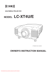
● Take appropriate space on the top, sides and rear of the projector
cabinet for allowing air circulation and cooling the projector.
Minimum distance should be taken. If the projector is to be built
into a compartment or similarly enclosed, the minimum distances
must be maintained. Do not cover the ventilation slot on the
projector. Heat build-up can reduce the service life of your
projector, and can also be dangerous.
SIDE and TOP
REAR
20cm
50cm
50cm
1m
● Do not put any flammable object or spray can near the projector, hot air is exhausted from the ventilation
holes.
● If the projector is not to be used for an extended time, unplug the projector from the power outlet.
READ AND KEEP THIS OWNER'S MANUAL FOR LATER USE.
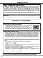
CAUTION
Not for use in a computer room as defined in the
Standard for the Protection of Electronic Computer/Data
Processing Equipment, ANSI/NFPA 75.
Ne puet être utillisé dans une salle d’ordinateurs telle
que définie dans la norme ANSI/NFPA 75 Standard for
Protection of Electronic Computer/Data Processing
Equipment
CAUTION
RISK OF ELECTRIC SHOCK
DO NOT OPEN
CAUTION :
TO REDUCE THE RISK OF ELECTRIC SHOCK, DO NOT REMOVE COVER (OR BACK). NO USERSERVICEABLE PARTS INSIDE EXCEPT LAMP REPLACEMENT. REFER SERVICING TO QUALIFIED
SERVICE PERSONNEL.
THIS SYMBOL INDICATES THAT DANGEROUS
VOLTAGE CONSTITUTING A RISK OF ELECTRIC
SHOCK IS PRESENT WITHIN THIS UNIT.
2
THIS SYMBOL INDICATES THAT THERE ARE IMPORTANT
OPERATING AND MAINTENANCE INSTRUCTIONS IN THE
OWNER'S MANUAL WITH THIS UNIT.
SAFETY INSTRUCTIONS
All the safety and operating instructions should be read before
the product is operated.
Read all of the instructions given here and retain them for later
use. Unplug this projector from AC power supply before
cleaning. Do not use liquid or aerosol cleaners. Use a damp
cloth for cleaning.
This projector should be operated only from the type of power
source indicated on the marking label. If you are not sure of
the type of power supplied, consult your authorized dealer or
local power company.
Follow all warnings and instructions marked on the projector.
Do not overload wall outlets and extension cords as this can
result in fire or electric shock. Do not allow anything to rest on
the power cord. Do not locate this projector where the cord
may be damaged by persons walking on it.
For added protection to the projector during a lightning storm,
or when it is left unattended and unused for long periods of
time, unplug it from the wall outlet. This will prevent damage
due to lightning and power line surges.
Do not attempt to service this projector yourself as opening or
removing covers may expose you to dangerous voltage or
other hazards. Refer all servicing to qualified service
personnel.
Do not expose this unit to rain or use near water... for
example, in a wet basement, near a swimming pool, etc...
Do not use attachments not recommended by the
manufacturer as they may cause hazards.
Do not place this projector on an unstable cart, stand, or table.
The projector may fall, causing serious injury to a child or
adult, and serious damage to the projector. Use only with a
cart or stand recommended by the manufacturer, or sold with
the projector. Wall or shelf mounting should follow the
manufacturer's instructions, and should use a mounting kit
approved by the manufacturers.
An appliance and cart combination should
be moved with care. Quick stops,
excessive force, and uneven surfaces
may cause the appliance and cart
combination to overturn.
Slots and openings in the back and bottom of the cabinet are
provided for ventilation, to insure reliable operation of the
equipment and to protect it from overheating.
Unplug this projector from wall outlet and refer servicing to
qualified service personnel under the following conditions:
a. When the power cord or plug is damaged or frayed.
b. If liquid has been spilled into the projector.
c. If the projector has been exposed to rain or water.
d. If the projector does not operate normally by following the
operating instructions. Adjust only those controls that are
covered by the operating instructions as improper
adjustment of other controls may result in damage and will
often require extensive work by a qualified technician to
restore the projector to normal operation.
e. If the projector has been dropped or the cabinet has been
damaged.
f. When the projector exhibits a distinct change in
performance-this indicates a need for service.
When replacement parts are required, be sure the service
technician has used replacement parts specified by the
manufacturer that have the same characteristics as the
original part. Unauthorized substitutions may result in fire,
electric shock, or injury to persons.
Upon completion of any service or repairs to this projector, ask
the service technician to perform routine safety checks to
determine that the projector is in safe operating condition.
The openings should never be covered with cloth or other
materials, and the bottom opening should not be blocked by
placing the projector on a bed, sofa, rug, or other similar
surface. This projector should never be placed near or over a
radiator or heat register.
This projector should not be placed in a built-in installation
such as a book case unless proper ventilation is provided.
Never push objects of any kind into this projector through
cabinet slots as they may touch dangerous voltage points or
short out parts that could result in a fire or electric shock.
Never spill liquid of any kind on the projector.
Voor de klanten in Nederland
Bij dit product zijn batterijen
geleverd.
Wanneer deze leeg zijn,
moet u ze niet weggooien
maar inleveren als KCA.
3
COMPLIANCES
Federal Communication Commission Notice
This equipment has been tested and found to comply with the limits for a Class A digital device, pursuant to Part
15 of FCC Rules. These limits are designed to provide reasonable protection against harmful interference when
the equipment is operated in a commercial environment. This equipment generates, uses, and can radiate radio
frequency energy and, if not installed and used in accordance with the instruction manual, may cause harmful
interference to radio communications. Operation of this equipment in a residential area is likely to cause harmful
interference in which case the user will be required to correct the interference at his own expense.
Do not make any changes or modifications to the equipment unless otherwise specified in the instructions. If such
changes or modifications should be made, you could be required to stop operation of the equipment.
CAUTION!
This is a Class A equipment. This equipment can cause interference in residential areas; in this case, the operator
can be asked to take adequate countermeasures.
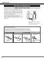
AC POWER CORD REQUIREMENT
The AC Power Cord supplied with this projector meets the requirement for use in the country you purchased it.
AC Power Cord for the United States and Canada :
AC Power Cord used in the United States and Canada is listed by the Underwriters
Laboratories (UL) and certified by the Canadian Standard Association (CSA).
AC Power Cord has a grounding-type AC line plug. This is a safety feature to be sure
that the plug will fit into the power outlet. Do not try to defeat this safety feature.
Should you be unable to insert the plug into the outlet, contact your electrician.
GROUND
AC Power Cord for the United Kingdom :
This cord is already fitted with a moulded plug incorporating a fuse, the value of which is indicated on the pin
face of the plug. Should the fuse need to be replaced, an ASTA approved BS 1362 fuse must be used of the
same rating, marked thus . If the fuse cover is detachable, never use the plug with the cover omitted. If a
replacement fuse cover is required, ensure it is of the same colour as that visible on the pin face of the plug
(i.e. red or orange). Fuse covers are available from the Parts Department indicated in your User Instructions.
If the plug supplied is not suitable for your socket outlet, it should be cut off and destroyed.
The end of the flexible cord should be suitably prepared and the correct plug fitted. (See Over)
ASA
WARNING : A PLUG WITH BARED FLEXIBLE CORD IS HAZARDOUS IF ENGAGED IN A LIVE SOCKET
OUTLET.
The Wires in this mains lead are coloured in accordance with the following code:
Green-and-yellow ············ Earth
Blue ································· Neutral
Brown ······························ Live
As the colours of the wires in the mains lead of this apparatus may not correspond with the coloured markings
identifying the terminals in your plug proceed as follows:
The wire which is coloured green-and-yellow must be connected to the terminal in the plug which is marked
by the letter E or by the safety earth symbol
or coloured green or green-and-yellow.
The wire which is coloured blue must be connected to the terminal which is marked with the letter N or
coloured black.
The wire which is coloured brown must be connected to the terminal which is marked with the letter L or
coloured red.
WARNING : THIS APPARATUS MUST BE EARTHED.
THE SOCKET-OUTLET SHOULD BE INSTALLED NEAR THE EQUIPMENT AND EASILY ACCESSIBLE.
4
TABLE OF CONTENTS
FEATURES AND DESIGN
6
DISPLAY ADJUST
DISPLAY ADJUSTMENTS
PREPARATION
7
NAME OF EACH PART OF PROJECTOR
SETTING-UP PROJECTOR
7
8
CONNECTING AC POWER CORD
LENS INSTALLATION
POSITIONING PROJECTOR
LENS SHIFT ADJUSTMENT
PICTURE LEVEL AND TILT ADJUSTMENT
MOVING PROJECTOR
8
9
9
9
10
10
CONNECTING PROJECTOR
11
TERMINALS OF PROJECTOR
CONNECTING TO COMPUTER
CONNECTING TO VIDEO EQUIPMENT
11
14
15
BEFORE OPERATION
SIDE CONTROLS AND INDICATORS
OPERATION OF REMOTE CONTROL
REMOTE CONTROL CODE CHANGE
AND OPERATING RANGE
REMOTE CONTROL BATTERIES INSTALLATION
OPERATING ON-SCREEN MENU
HOW TO OPERATE ON-SCREEN MENU
FLOW OF ON-SCREEN MENU OPERATION
MENU BAR
BASIC OPERATION
TURNING ON / OFF PROJECTOR
ADJUSTING SCREEN
ZOOM ADJUSTMENT
FOCUS ADJUSTMENT
LENS SHIFT ADJUSTMENT
PICTURE FREEZE FUNCTION
NO SHOW FUNCTION
SOUND ADJUSTMENT
SELECTING INPUT SOURCE
SYSTEM SELECT
AUTOMATIC MULTI-SCAN SYSTEM
SELECT COMPUTER SYSTEM MANUALLY
SELECT VIDEO SYSTEM
16
16
18
19
19
SCREEN ADJUSTMENTS
AUTO PC ADJUSTMENT
MANUAL DISPLAY ADJUSTMENTS
IMAGE ADJUSTMENTS
IMAGE LEVEL SELECT
IMAGE LEVEL ADJUSTMENTS
SETTING
SETTING MENU
APPENDIX
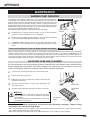
MAINTENANCE
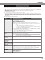
WARNING TEMP. INDICATOR
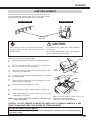
AIR FILTER CARE AND CLEANING
LAMP MANAGEMENT
LAMP REPLACEMENT
CLEANING PROJECTION LENS
TROUBLESHOOTING
INDICATORS AND PROJECTOR CONDITION
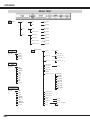
MENU TREE
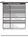
TECHNICAL SPECIFICATIONS
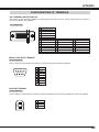
CONFIGURATIONS OF TERMINALS
COMPATIBLE COMPUTER SPECIFICATIONS
OPTIONAL PARTS
28
28
28
29
30
32
32
33
35
35
39
39
39
39
40
41
42
43
45
46
48
49
50
51
20
20
20
21
22
22
23
23
23
23
23
23
24
25
26
26
26
27
TRADEMARKS
● Apple, Macintosh, and PowerBook are trademarks or registered trademarks of Apple Computer,Inc.
● IBM and PS/2 are trademarks or registered trademarks of International Business Machines, Inc.
● Windows and PowerPoint are registered trademarks of Microsoft Corporation.
● Each name of corporations or products in the owner's manual is a trademark or a registered trademark of its
respective corporation.
5
FEATURES AND DESIGN
This Multimedia Projector is designed with most advanced technology for portability, durability, and ease of use. This
projector utilizes built-in multimedia features, a palette of 16.77 million colors, and matrix liquid crystal display (LCD)
technology.
◆
Compatibility
This projector widely accepts various video and
computer input signals including;
● Computers
IBM-compatible or Macintosh computer up to 1600
x 1200 resolution.
● 6 Color Systems
NTSC, PAL, SECAM, NTSC 4.43, PAL-M or PALN color system can be connected.
● Component Video
Component video signal, such as a DVD player
output high definition TV signals including 480i,
480p, 575i, 575p, 720p, 1035i, 1080i-50 or 1080i60, can be connected.
● S-Video
S-Video signal, such as a S-VHS VCR output
signal, can be connected.
◆
High Resolution Image
This projector provides 1920 x 1080 dots resolution for
computer input and 1100 horizontal TV lines. This
projector cannot display image of over 1600 x 1200 dots.
When resolution of your computer is over than 1600 x
1200, reset a computer output for lower resolution.
◆
Multi-Scan System
This projector has Multi-Scan System to conform to
almost all computer output signals quickly. There is no
need for troublesome manual adjustment of frequency
and other settings.
◆
One-Touch Auto PC Adjustment
Incoming computer video signals are recognized and
best adjustment is automatically set by Auto PC
Adjustment. No complicated setup is necessary and
projection is always precise.
◆
Progressive Scan Function
This function converts interlace video signals into
progressive scan signals and provide fine picture quality.
◆
Motor-driven Lens Shift
Projection lens can be moved up, down left and right with
motor-driven lens shift function. This function makes it
easy to provide projected image where you want.
Zoom and focus can be also adjusted with motor-driven
operation.
6
◆
Power Management
Power Management function is provided to reduce power
consumption while a projector is not in use.
This Power Management function operates to turn
Projection Lamp off when a projector detects signal
interruption and any button is not pressed. Projection
Lamp is automatically turned on again when a projector
detects signal or any operation button is pressed.
This projector is shipped with this function ON.
◆
Digital Visual Interface
This projector is equipped with DVI 29-pin terminal for
connecting DVI output from a computer.
◆
Multi Versatile Platform
This projector applies various input/output terminals and
4 terminal slots for expansion to tune to diversity of
signals from computers and video equipment.
◆
Selectable Terminal Slots
4-built-in Terminal Slots enable you to arrange any
combinations of input sources just by changing Terminal
Boards. For Terminal Boards, contact sales dealer
where you purchased a projector.
◆
Multilanguage Menu Display
Operation menu is displayed in; English, German,
French, Italian, Spanish, Portuguese, Dutch, Swedish,
Russian, Chinese, Korean or Japanese.
◆
Network board (Optional)
Network board is an optional product to control and set
up a projector via the network cable. By accessing to the
connected projector using the web browser on your
computer. It can be controlled and set up the projector
remotely. Contact the sales dealer where you purchased
this projector for optional parts.
PREPARATION
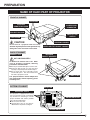
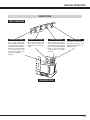
NAME OF EACH PART OF PROJECTOR
FRONT OF CABINET
SPEAKERS
INFRARED
REMOTE RECEIVER
POWER CORD
CONNECTOR
PROJECTION LENS
MAIN ON / OFF
SWITCH
LENS COVER
CAUTION
Do not turn on a projector with lens cover
attached. High temperature from light beam may
damage lens cover and result in fire hazard.
CARRYING HANDLE
LEVEL AND TILT ADJUST HANDLE
BACK OF CABINET
EXHAUST VENT
INFRARED
REMOTE RECEIVER
HOT AIR EXHAUSTED !
Air blown from exhaust vent is hot. When
using or installing a projector, following
precautions should be taken.
● Do not put a flammable object near this vent.
● Keep rear grills at least 3.3’ (1m) away from
any object, especially heat-sensitive object.
● Do not touch this area, especially screws
and metallic parts. This area will become
hot while a projector is used.
This projector detects internal temperature
and automatically controls operating power
of Cooling Fans.
LAMP COVER
BOTTOM OF CABINET
AIR FILTER
AIR INTAKE VENTS
This projector is equipped with cooling
fans for protection from overheating.
Pay attention to following to ensure
proper ventilation and avoid a possible
risk of fire and malfunction.
● Do not cover vent slots.
● Keep bottom clear of any objects.
Obstructions may block cooling air.
ADJUSTABLE FEET
ADJUSTABLE FEET
7
PREPARATION
SETTING-UP PROJECTOR
CONNECTING AC POWER CORD
This projector uses nominal input voltages of 120 V or
200-240 V AC. This projector automatically selects
correct input voltage. It is designed to work with singlephase power systems having a grounded neutral
conductor. To reduce risk of electrical shock, do not plug
into any other type of power system.
Consult your authorized dealer or service station if you
are not sure of type of power supply being in use.
Connect a projector with peripheral equipment before
turning a projector on. (Refer to pages 12 ~ 15 for
connection.)
Connect AC Power Cord (supplied) to
a projector.
AC outlet must be near this equipment
and must be easily accessible.
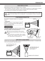
NOTE ON POWER CORD
AC Power Cord must meet requirement of country where you use a projector.
Confirm AC plug type with chart below and proper AC power cord must be used.
If supplied AC Power Cord does not match AC outlet, contact your sales dealer.
Projector side
AC Outlet side
For the U.S.A. and Canada
For Continental Europe
For the U.K.
Ground
To POWER CORD
CONNECTOR on a
projector.
8
To the AC Outlet.
To the AC Outlet.
(120 V AC)
To the AC Outlet.
(200 - 240 V AC)
(200 - 240 V AC)
PREPARATION
LENS INSTALLATION
Before setting up a projector, install Projection Lens on a Projector.
1. Before installation, check where a projector is used and prepare suitable lens. For specifications of Projection
Lens, refer to manual separately attached or contact sales dealer where you purchased a projector.
2. For installation, refer to installation manual supplied to a Projector.
When moving or setting up a projector, be sure to replace a Lens Cover to protect a surface. And be
careful not to hold or subject a lens to strong forces. It may damage lens, cabinet, or mechanical
parts.
POSITIONING PROJECTOR
This projector is designed to project on a flat projection
surface.
SCREEN
ROOM LIGHT
Brightness in room has a great influence on picture
quality. It is recommended to limit ambient lighting in
order to provide best image.
VENTILATION
This projector is equipped with cooling fan to protect it from overheating. Pay attention to following to ensure proper ventilation
and avoid a possible risk of fire and malfunction.
● Do not cover vents with papers or other materials.
● Keep rear grill at least 3.3 feet (1 m) away from any
object.
● Make sure that there are no objects under a projector.
An object under a projector may prevent a projector
from taking cooling air through bottom vent.
AIR INTAKE VENT
(BOTTOM SIDE)
EXHAUST VENT
(REAR SIDE)
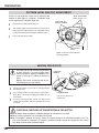
LENS SHIFT ADJUSTMENT
Projection lens can be moved up, down, left and right with motor-driven lens shift function. This function makes
it easy to provide projected image where you want.
Use LENS SHIFT button and
POINT UP/DOWN button to
move image up or down.
(Refer to page 23.)
Use LENS SHIFT button and
POINT LEFT/RIGHT button to
move image left or right.
(Refer to page 23.)
MOVED UP OR DOWN
MOVED LEFT OR RIGHT
9
PREPARATION
PICTURE LEVEL AND TILT ADJUSTMENT
Picture tilt and projection angle can be adjusted with
handles on both sides of a projector. Projection angle
can be adjusted to 5.7 degrees upper way.
1
Press knob on handle. Handle pop out.
2
Turn handles (right and left) until picture is projected on
proper position. Adjust height of rear adjustable feet by
rotating them until projector properly stabled on table.
3
Press knob and retract handle.
REAR ADJUSTABLE
FEET. (Refer to P7).
LEVEL AND TILT
ADJUST HANDLE
KNOB
ADJUSTABLE
FEET
Height of front feet can be adjusted
by turning handles.
MOVING PROJECTOR
For safety, be sure to hold Carrying Handles
on both sides by 2 or more people when
moving a projector. Moving it unproperly may
result in damage of cabinet or person's
injury.
Replace lens cover and retract feet to prevent damage to lens and cabinet.
1
Pull up lock buttons on each side of carrying handles
and release locks.
2
Pull carrying handles out fully until it's locked (with a
click). Move a projector by holding two handles by 2 or
more people.
3
CARRYING
HANDLE
LOCK BUTTONS
Pull up lock buttons to
release lock.
To retract carrying handles, pull up lock buttons and
release lock of handles and press handles fully in until
it's locked.
CAUTION IN CARRYING OR TRANSPORTING A PROJECTOR
● Do not drop or bump a projector, otherwise damages or malfunctions may result.
● When carrying a projector, use a suitable carrying case.
● Do not transport a projector by using a courier or transport service in an unsuitable transport case. This
may cause damage to a projector. To transport a projector through a courier or transport service, consult
your dealer and best case should be applied.
10
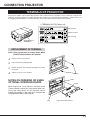
CONNECTING PROJECTOR
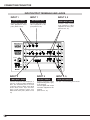
TERMINALS OF PROJECTOR
This projector applies various input/output terminals and 4 terminal slots for expansion to tune to diversity of signals from
computers and video equipment. 4-built-in Terminal Slots enable you to arrange desired combinations of input sources just
by changing Terminal Boards. For Terminal Boards, contact sales dealer where you purchased a projector.
3 TERMINAL SLOTS (Factory set)
G/Y
B/Pb
H/HV
V
AUDIO
R
USB
DVI
AUDIO
R
SDI Terminal
5 BNC Terminal
CONTROL PORT
L
(MONO)
R/C JACK
INPUT 1
R/Pr
SDI OUT
INPUT 2
SERIAL PORT OUT
SDI IN1 SDI IN2
CONTROL PORT
L
INPUT 3
SERIAL PORT IN
DVI Terminal
(MONO)
AUDIO OUT
L
INPUT 4
R
INPUT/OUTPUT
TERMINALS
RESET
(MONO)
REPLACEMENT OF TERMINAL
NOTE; When replacement of terminal board, MAIN
ON/OFF switch should be OFF position.
1
Remove 2 Screws on terminal.
2
Pull out terminal by holding handle.
3
Replace terminal. Insert terminal along Guide to fit Plug
into Socket.
4
Tighten screws to secure terminal.
Screws
NOTES ON ORDERING OR USING
OPTIONAL INTERFACE BOARD
Guide
Socket
When ordering or using Optional Interface Board
(Terminal Board), contact your sales dealer. When contacting the sales dealer, tell the Optional Control
Number (Op.cont.No.) in the menu that is located under
Language Select Menu. (See page 35.)
Plug
Figure shows DVI terminal.
11
CONNECTING PROJECTOR
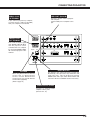
INPUT/OUTPUT TERMINALS AND JACKS
INPUT 1
INPUT 1
INPUT 2, 3
SDI INPUT JACKS
SDI OUTPUT JACK
AUDIO INPUT JACKS
Connect SDI output from
video equipment to these
jacks. (Refer to P15.)
Connect SDI input from
video equipment to this
jack. (Refer to P15.)
Connect audio output
from computer or video
equipment to these jacks.
(Refer to P14, 15.)
SDI IN1 SDI IN2
SDI OUT
INPUT 1
SERIAL PORT IN
R/Pr
G/Y
B/Pb
H/HV
V
AUDIO
R
CONTROL PORT
INPUT 2
SERIAL PORT OUT
L
(MONO)
USB
AUDIO
DVI
R
CONTROL PORT
L
INPUT 3
R/C JACK
(MONO)
AUDIO OUT
L
INPUT 4
R
RESET
(MONO)
INPUT 2
5 BNC INPUT JACKS
Connect component video output (Cr, Y,
Cb or Pr, Y, Pb) from video equipment to
R/Pr, G/Y and B/Pb jacks or connect
computer output [5 BNC Type (Red,
Green, Blue, Horiz. Sync and Vert.
Sync.)] from computer to R/Pr, G/Y,
B/Pb, H/HV and V jacks. (Refer to P14,
15)
12
INPUT 3
DVI INPUT TERMINAL
Connect computer output
(Digital/Analog DVI-I type)
to this terminal.
Connect digital video output
from video equipment to this
terminal.
(Refer to P14, 15.)
INPUT 2, 3,
CONTROL PORT CONNECTORS
The port is not functioning in this model.
CONNECTING PROJECTOR
USB PORT (Series B)
SERIAL PORT
IN TERMINAL
This port is used to control a projector
with computer.
Connect USB port of computer to this
port.
If you control a projector by computer,
you must connect a cable (not provided)
from your computer to this terminal.
SDI IN1 SDI IN2
SDI OUT
INPUT 1
SERIAL PORT IN
SERIAL PORT
OUT TERMINAL
R/Pr
G/Y
B/Pb
H/HV
V
AUDIO
R
CONTROL PORT
INPUT 2
SERIAL PORT OUT
L
(MONO)
R/C JACK
USB
DVI
AUDIO
R
CONTROL PORT
L
INPUT 3
This terminal outputs signal
from SERIAL PORT IN. More
than two projectors can be
controlled with one computer
by connecting SERIAL PORT
IN. of another projector to this
terminal.
(MONO)
AUDIO OUT
L
INPUT 4
R
RESET
(MONO)
R/C JACK
When using Wired / Wireless Remote
Control Unit as Wired Remote
Control, Connect Wired Remote
Control Unit to this jack with Remote
Control Cable (supplied).
(Refer to page 18.)
RESET BUTTON
This projector uses a micro processor to control unit.
Occasionally, micro processor may malfunction and
need to be reset. This can be done by pressing
RESET button with a pen, which will shut down and
restart unit. Do not use RESET function excessively.
AUDIO OUTPUT JACKS
Connect an external audio
amplifier to these jacks.
(Refer to P14, 15.)
13
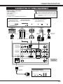
CONNECTING PROJECTOR
CONNECTING TO COMPUTER
Cables used for connection (✽ = Cables are not supplied with this projector.)
• DVI Cable
• DVI-VGA Cable (HDB 15 pin)
• MAC/VGA Adapter
• BNC Cable (BNC x 5) ✽
• Audio Cables (RCA x 2) ✽
NOTE :
When connecting cable, power cords of both a
projector and external equipment should be
disconnected from AC outlet. Turn a projector
and peripheral equipment on before computer is
switched on.
IBM-compatible computers or Macintosh computers (VGA / SVGA / XGA / SXGA/UXGA)
Desktop type
Monitor Output
Monitor Output
Laptop type
Monitor Output
Audio Output
MAC/VGA
Adapter
Set slide switches
following chart
below.
DVI Cable
Audio Cable
(stereo) ✽
BNC Cable ✽
DVI-VGA Cable
SDI IN1 SDI IN2
SDI OUT
INPUT 1
SERIAL PORT IN
R/Pr
G/Y
B/Pb
H/HV
V
AUDIO
R
CONTROL PORT
INPUT 2
SERIAL PORT OUT
L
(MONO)
USB
DVI
Terminals of
a Projector
CONTROL PORT
AUDIO
R
INPUT 3
R/C JACK
L
(MONO)
AUDIO OUT
L
INPUT 4
R
RESET
AUDIO OUT
(MONO)
MAC/VGA ADAPTER
ON
Switches of
MAC/VGA Adapter
Audio Cable
(stereo) ✽
ON
DIP
1 2 3 4 5 6
OFF
Set switches as shown in table below depending on
RESOLUTION MODE that you want to use before
your turn on a projector and computer
Audio Input
External Audio Equipment
Audio Amplifier
14
Audio Speaker
(stereo)
MODE
SWITCHES
1
2
3
4
5
6
13"MODE (640 x 480)
ON
ON OFF OFF OFF OFF
16"MODE (832 x 624)
OFF ON OFF ON OFF OFF
19"MODE (1024 x768)
OFF ON
ON OFF OFF OFF
21"MODE (1152 x 870)
ON
ON
ON
ON OFF OFF
CONNECTING PROJECTOR
CONNECTING TO VIDEO EQUIPMENT
Cables used for connection
NOTE :
When connecting cable, power cords of both a
projector and external equipment should be
disconnected from AC outlet. Turn a projector
and peripheral equipment on before computer is
switched on.
• Video Cable (BNC)✽
• Audio Cable (RCA x 2) ✽
• Scart Cable ✽
• DVI-VGA Adapter ✽
(✽ = Cables are not supplied with this projector.)
Video Source (example)
SDI Output
Digital Video Output
Component video output equipment.
Video Equipment with
SDI signal output/input
Video Equipment with
Digital video signal output
SDI Input
(such as DVD player or
high-definition TV source.)
Component Video Output
Pr/Cr
BNC Cable ✽
DVI
Y
DVI-VGA
Adapter ✽
BNC Cable ✽
SDI IN 1/SDI IN 2 SDI OUTPUT
Audio Output
RGB Scart
21-pin Output
Pb/Cb
R
L
Audio Cable
(Stereo) ✽
Scart
Cable ✽
AV AUDIO IN
Pr/Cr-Y-Pb/Cb
DVI
SDI IN1
SDI IN2
R/Pr
G/Y
SDI OUT
INPUT 1
SERIAL PORT IN
B/Pb
H/HV
V
CONTROL PORT
AUDIO
R
INPUT 2
SERIAL PORT OUT
L
(MONO)
USB
DVI
CONTROL PORT
AUDIO
R
INPUT 3
R/C JACK
L
(MONO)
AUDIO OUT
L
INPUT 4
R
RESET
(MONO)
Terminals of
a Projector
AUDIO OUT
External Audio Equipment
Audio Cable
(Stereo) ✽
Audio Amplifier
Audio Speaker (stereo)
Audio Input
15
BEFORE OPERATION
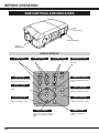
SIDE CONTROLS AND INDICATORS
REAR
INDICATORS
SIDE CONTROLS
FRONT
INDICATORS
SIDE CONTROLS
ZOOM buttons
Adjust zoom. (P23)
FOCUS buttons
Adjust volume. (P24)
Adjust focus. (P23)
ZOOM
VOLUME buttons
FOCUS
VOLUME
MENU button
LENS SHIFT button
Select LENS SHIFT function.
(P23)
SELECT button
LENS SHIFT
MENU
INPUT 1/2
INPUT 3/4
SELECT
INPUT 1/2 button
Select input source either
INPUT 1 or INPUT 2. (P25)
AUTO PC ADJ. button
INPUT 3/4 button
Operates the AUTO PC
adjustment function. (P29)
Select input source either
INPUT 3 or INPUT 4. (P25)
AUTO PC ADJUST
IMAGE
POINT buttons
Selects an item or adjusts
value in the On-Screen Menu.
(P20)
16
Turns the projector on or
off. (P22)
ON-OFF
Open or close the On-Screen
Menu operation. (P20, 21)
Executes the item selected.
(P20)
POWER ON–OFF button
IMAGE button
Selects image levels.
(P32)
BEFORE OPERATION
INDICATORS
FRONT INDICATORS
LAMP
READY
LAMP
REPLACE
WARNING
TEMP.
LAMP REPLACE indicator
WARNING TEMP. indicator
This LAMP REPLACE
indicator lights yellow when
any of Projection Lamps is
nearing its end, and flashes
when any of them becomes
out. Check which lamp
needs to be replaced on
Lamp Status Display.
(P40-41)
This indicator flashes red
when internal projector
temperature is too high.
(P39)
READY indicator
LAMP indicator
This indicator lights green
when a projector is ready to
be turned on. And it flashes
green in Power Management
mode or internal projector
temperature is to high.
(P37, 39)
This indicator is dim when a
projector is turned on. And
bright when a projector is in
stand-by mode.
LAMP
READY
WARN
ING
TEMP
.
LA P
REPLM
ACE
REAR INDICATORS
17
BEFORE OPERATION
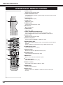
OPERATION OF REMOTE CONTROL
q SELECT button
Executes the item selected. (P20)
w SIGNAL EMISSION indicator
This indicator lights red while a signal is being sent from the remote control
to the projector.
e SCREEN button
Select image screen. (P28)
r ZOOM button
q
Adjust zoom. (P23)
t FREEZE button
Freezes the projected picture. (P23)
y MUTE button
Mutes sound. (P24)
u FOCUS button
Adjust focus. (P23)
i POINT (UP/DOWN/LEFT/RIGHT) button
Selects an item or adjusts value in the On-Screen Menu. (P20)
Point Left/Right button are also used as VOLUME +/- button. (P24)
o SELECT button
Executes the item selected. (P20)
!1
!2
▲
ZOOM
!3
▲
!4
!5
FOCUS
▲
u
!0 IMAGE (1-10) buttons
Selects image levels (IMAGE 1 - IMAGE 10). (P32)
ON-OFF
▲
w
e
r
t
y
!6
!1 WIRED REMOTE JACK
When using as Wired Remote Control, connect Remote Control Cable to
this jack.
Battery installation is required when using as Wired Remote Control.
!2 POWER ON-OFF button
Turns the projector on or off. (P22)
!3 AUTO PC button
i
Operates the Auto PC adjustment function. (P29)
!4 NO SHOW button
SELECT
Turns the picture into black image. (P23)
o
!5 MENU button
Opens or closes the On-Screen Menu. (P20)
!7
!0
!6 LENS SHIFT button
Select LENS SHIFT function. (P23)
!7 INPUT 1-4 buttons
Select input source (INPUT 1-INPUT 4). (P25)
!8
RESET
!9
!8 IMAGE button
Selects image levels. (P32)
!9 RESET switch
Slide this switch to the "RESET" to initialize the remote control code.
(P19, 37)
18
BEFORE OPERATION
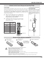
Remote Control Code Change and Operating Range
Code Change
This projector has eight different remote control codes (Code 1-Code 8); the
factory-set, initial code (Code 1) and the other seven codes (Code 2 to Code 8).
This switching function prevents remote control interference when operating
several projectors or video equipment at the same time. (Change the remote
control code for the projector first before changing that for the remote control. See
“Remote control” on page 37.)
1
While pressing the MENU button, press the IMAGE button
number of times corresponding to each remote control code
number. Each time you press the IMAGE button, the code is
changed sequentially. (See the list below.)
2
To initialize the remote control code for the remote control,
slide the RESET switch to the RESET, and then to the ON.
The initial code is Code 1.
Remote Control Code
Number of Times of
Pressing IMAGE
Button
Code 1
1
Code 2
2
Code 3
3
Code 4
4
Code 5
5
Code 6
6
Code 7
7
Code 8
8
Operating Range
Point Remote Control Unit toward
projector (Receiver Window)
whenever pressing any button.
Maximum operating range for
Remote Control Unit is about 16.4’
(5m) and 60° in front and rear of a
projector.
60°
16.4’
(5 m)
ON-OFF
▲
ZOOM
▲
▲
FOCUS
MENU button
▲
SELECT
16.4’
(5 m)
60°
IMAGE button
RESET
Remote Control Batteries Installation
1
Remove battery
compartment lid.
Press lid downward and slide it.
2
Slide batteries into
compartment.
3
Replace compartment lid.
Two AA size batteries
For correct polarity (+ and
–), be sure battery
terminals are in contact
with pins in compartment.
To insure safe operation, please observe following precautions :
● Use (2) AA, UM3 or R06 type alkaline batteries.
● Replace two batteries at same time.
● Do not use a new battery with an used battery.
● Avoid contact with water or liquid.
● Do not expose Remote Control Unit to moisture, or heat.
● Do not drop Remote Control Unit.
● If a battery has leaked on Remote Control Unit, carefully wipe case clean and install new batteries.
● Danger of explosion if battery is incorrectly replaced.
● Dispose of used batteries according to the batteries manufacturers instructions and local rules.
19
BEFORE OPERATION
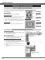
OPERATING ON-SCREEN MENU
ON-OFF
HOW TO OPERATE ON-SCREEN MENU
ZOOM
WIRELESS REMOTE CONTROL
FOCUS
▲
You can control and adjust this projector through ON-SCREEN
MENU. Refer to following pages to operate each adjustment on
ON-SCREEN MENU.
MENU BUTTON
1 DISPLAY MENU
Press MENU button to display ON-SCREEN MENU.
POINT BUTTON
Used to move Pointer
UP/ DOWN/ RIGHT/
LEFT.
SELECT
2 MOVING POINTER
Move pointer (✽ see below) or adjust value of item by pressing
POINT button(s) on Side Control or on Remote Control Unit.
✽ Pointer is a icon on ON-SCREEN MENU to select item. See figures on section "FLOW OF ON-SCREEN MENU OPERATION"
below.
SELECT BUTTON
Used to select item.
SIDE CONTROL
LENS SHIFT
MENU
3 SELECT ITEM
Select item or set selected function by pressing SELECT button.
I
I
SELECT
RESET
MENU BUTTON
POINT BUTTONS
Used to move Pointer
UP/ DOWN/ RIGHT/
LEFT.
SELECT BUTTON
Used to select item.
AUTO PC ADJUST
IMAGE
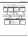
FLOW OF ON-SCREEN MENU OPERATION
Display ON-SCREEN MENU
1
Press MENU button to display ON-SCREEN MENU (MENU
BAR). A red frame is POINTER.
Select Menu to be adjusted
2
Move POINTER (red frame) to MENU ICON that you want to
select by pressing POINT RIGHT / LEFT buttons.
Control or adjust item through ON-SCREEN MENU
3
4
MENU ICON
MENU BAR
Press POINT UP/DOWN button and move POINTER (red
frame or red arrow) to ITEM that you want to adjust, and then
press SELECT button to show ITEM DATA.
Adjust ITEM DATA by pressing POINT RIGHT / LEFT
buttons.
Refer to following pages for details of respective
adjustments.
POINTER
POINTER (red frame)
(red frame)
Press POINT DOWN button to
move POINTER.
ITEM
SELECT
BUTTON
ITEM DATA
Press POINT LEFT/RIGHT
buttons to adjust value or
set function.
20
BEFORE OPERATION
MENU BAR
GUIDE WINDOW
Shows selected
item of ONSCREEN MENU.
SYSTEM BOX
Used to select computer
system or video system.
Shows selected system
on this box.
(Refer to P26-27)
INPUT MENU
Used to select input
source (Input 1, Input 2,
Input 3 or Input 4). Refer
to P25.
DISPLAY ADJUST MENU
SETTING MENU
Used to adjust size of
image.
{Full/Normal/Anamorphic}
(Refer to P28)
Used to adjust parameters
to match with input signal
format. (Refer to P30-31)
Used to change settings
of projector or reset Lamp
Replace Counter.
(Refer to P35-38)
IMAGE ADJUST MENU
Used to select image level among Standard (AV),
Cinema, Standard (PC), Real and Image 1 ~ 10.
(Refer to P32)
Used to adjust image.
[Contrast/Brightness/Color/Tint/Color Temp.
/White Balance (R/G/B)/Sharpness/Detail
Enhancer /Gamma/Noise
Reduction/Progressive/Auto picture control/Auto
Lamp Control] (Refer to P33-34)
SOUND MENU
Used to adjust sound
[volume, Bass or Treble],
to select Built-in SP OnOff and Sound Mute.
(Refer to P24)
21
BASIC OPERATION
TURNING ON / OFF PROJECTOR
TURNING ON PROJECTOR
1
Complete peripheral connections (with Computer, VCR, etc.)
before turning on projector. (Refer to "CONNECTING TO
PROJECTOR" on Pages 12~15 for connecting that equipment.)
2
Connect a projector's AC Power Cord into a wall outlet and turn
MAIN ON/OFF SWITCH to ON. LAMP indicator lights RED, and
READY indicator lights GREEN.
3
Press POWER ON-OFF button on Side Control or on Remote
Control Unit to ON. LAMP indicator dims, and Cooling Fans start
to operate. Preparation Display appears on a screen and countdown starts. Signal from source appears after 30 seconds.
Current Input and Lamp status are also displayed on screen for
5 seconds. (Refer to "LAMP MANAGEMENT" on page 40.)
INPUT AND LAMP STATUS
30
Preparation Display disappears after
30 seconds.
TURNING OFF PROJECTOR
1
Press POWER ON-OFF button on Side Control or on Remote
Control Unit, and a message "Power off?" appears on a screen.
2
Press POWER ON-OFF button again to turn off projector. LAMP
indicator lights bright and READY indicator turns off. After
approximate 90 seconds, READY indicator will light green again
and projector may be turned on by pressing POWER ON-OFF
button.
3
Message disappears after 4 seconds.
Cooling fans will operate for approximate 2 minutes after projector is turned off. To power down completely, turn MAIN ON/OFF
SWITCH to OFF and disconnect AC Power Cord.
TO MAINTAIN LIFE OF LAMP, ONCE YOU TURN
PROJECTOR ON, WAIT AT LEAST 5 MINUTES BEFORE
TURNING IT OFF.
When “Power Management” function mode is Ready or Shut down, projector detects signal interruption and turns off the
Projection Lamp automatically. Refer to “Power management” on page 37.
When WARNING TEMP. Indicator is flashing, projector cannot be turned on, refer to the section "MAINTENANCE" on page 39.
When the both WARNING TEMP. and READY Indicator flashing, refer to the section "MAINTENANCE" on page 39.
Do not use the projector continuously for 24 hours or more. If using the projector continuously for long periods,
turn it off and leave it for one hour at least once during a 24 hour period.
If you use the projector continuously for long period, it can excessively shorten the life of the lamp.
22
BASIC OPERATION
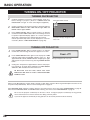
ADJUSTING SCREEN
ZOOM ADJUSTMENT
1
Press ZOOM ▲/▼ button on Side Control or on Remote Control
Unit. Message “Zoom” is displayed.
2
Press ZOOM ▲ button to make image larger, and press ZOOM
▼ button to make image smaller.
Message disappears after 4 seconds.
FOCUS ADJUSTMENT
1
Press FOCUS ▲/▼ button on Side Control or on Remote Control
Unit. Message “Focus” is displayed.
2
Adjust focus of image by pressing FOCUS ▲/▼ button(s) .
Message disappears after 4 seconds.
LENS SHIFT ADJUSTMENT
1
Press the LENS SHIFT button on Side Control or on the Remote
Control Unit. Message “Lens shift” is displayed.
2
Press POINT UP button to move image up, press POINT DOWN
button to move image down, press POINT LEFT to move image
left and press POINT RIGHT to move image right.
Message disappears after 4 seconds.
PICTURE FREEZE FUNCTION
Press FREEZE button on Remote Control Unit to freeze picture on-screen. To cancel FREEZE function, press FREEZE
button again or press any other button.
NO SHOW FUNCTION
Press NO SHOW button on Remote Control Unit to black out image.
To restore to normal, press NO SHOW button again or press any
other button.
Message disappears after 4 seconds.
23
BASIC OPERATION
SOUND ADJUSTMENT
DIRECT OPERATION
Indicates roughly level of
volume.
Volume
Press VOLUME (+/–) button(s) on Side Control or on Remote Control
Unit to adjust volume. Volume dialog box appears on screen for a few
seconds.
(+) button to increase volume, and (–) button for decreasing.
Mute
Press MUTE button on Remote Control Unit to cut off sound. To
restore sound to its previous level, press MUTE button again or press
Volume (+/–) button(s).
Press MUTE button to set
Mute function On or Off.
Display disappears after 4 seconds.
MENU OPERATION
1
2
Press MENU button and ON-SCREEN MENU will appear. Press
POINT LEFT/RIGHT buttons to move a red frame pointer to
SOUND Menu icon.
Press POINT DOWN button to move a red frame pointer to item
that you want to select, and then press SELECT button.
SOUND MENU
Indicates roughly
level of volume.
Volume
To increase volume, press POINT RIGHT button, and press POINT
LEFT button for decreasing.
Treble
To adjust Treble sound, press POINT RIGHT button or POINT LEFT
button.
Bass
To adjust Bass sound, press POINT RIGHT button or POINT LEFT
button.
Built-in SP.
Press POINT LEFT/RIGHT button(s) to switch built-in speaker on and
off.
Mute
Press POINT LEFT/RIGHT button(s) to cut off sound. Dialog box
display is changed to “On” and sound is cut off. To restore sound to
its previous level, press POINT LEFT/RIGHT button(s) again.
Quit
Closes SOUND MENU.
24
Close SOUND Menu.
SOUND Menu icon
BASIC OPERATION
SELECTING INPUT SOURCE
DIRECT OPERATION
Select INPUT source by pressing INPUT 1/2 and INPUT 3/4
buttons on Side Control or INPUT 1, INPUT 2, INPUT 3 and
INPUT 4 on Remote Control Unit.
INPUT 1/2 button
INPUT 1-4 buttons
INPUT 1
INPUT 1
INPUT 2
INPUT 2
INPUT 3/4 button
MENU OPERATION
1
2
Press MENU button and ON-SCREEN MENU will appear. Press
POINT LEFT/RIGHT buttons to select Input and press SELECT
button. Another dialog box INPUT SELECT Menu will appear.
INPUT 3
INPUT 3
INPUT 4
INPUT 4
INPUT MENU
Press POINT DOWN button and a red-arrow icon will appear.
Move arrow to INPUT source that you want to select, and then
press SELECT button.
INPUT Menu icon
Move arrow to INPUT source
that you want to select, and
then press SELECT button.
WHEN SELECT INPUT 1 (SDI TERMINAL )
Move a pointer to either SDI 1 or SDI 2 and press SELECT button.
WHEN SELECT INPUT 2 (5 BNC TERMINAL)
Input 1
Move a pointer to source that you want to select and press SELECT
button.
Input 2
RGB
When connect a computer output [5 BNC Type (Red, Green, Blue,
Horiz. Sync and Vert. Sync.)] from a computer to R/Pr, G/Y, B/Pb,
H/HV and V jacks.
Y, Pb/Cb, Pr/Cr
When connect component video output (Cr, Y, Cb or Pr, Y, Pb) from
video equipment to R/Pr, G/Y and B/Pb jacks.
Input 3
WHEN SELECT INPUT 3 (DVI TERMINAL)
Move a pointer to source that you want to select and press SELECT
button.
RGB(Analog)
When your computer is connected to INPUT 3 (ANALOG) terminal,
select RGB(Analog).
RGB(Scart)
When video equipment is connected to INPUT 3 (ANALOG) terminal,
select RGB(Scart).
RGB(PC Digital)
When your computer is connected to INPUT 3 (DIGITAL) terminal,
select RGB(PC Digital).
RGB(AV HDCP)
If a HDCP-compatible signal source is connected to the INPUT 3
(DIGITAL) terminal, select RGB(AV HDCP).
NOTE;
HDCP (High-bandwidth Digital Content
Protection) is a system for protecting digital
entertainment content which is delivered by DVI
(Digital Visual Interface) from being copied.
The specification of HDCP is decided and
controlled by Digital Content Protection, LLC.
Should the specification be changed, this
projector may not display the digital content
protected by HDCP.
25
BASIC OPERATION
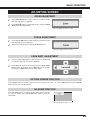
SYSTEM SELECT
AUTOMATIC MULTI-SCAN SYSTEM
This projector automatically tunes to most different types of computers based on VGA, SVGA, XGA, SXGA or UXGA (refer
to “COMPATIBLE COMPUTER SPECIFICATION” on pages 50-51). When a computer is selected, this projector
automatically tunes to incoming signal and projects the proper image without any special setting. (Some computers need to
be set manually.)
The projector displays one of the Auto, -----, Mode 1 ~ Mode 20, or the system provided in the projector.
Auto
––––
Mode 1
When projector cannot recognize connected signal as PC
system provided in this projector, Auto PC Adjustment
function operates to adjust projector and message “Auto”
is displayed on SYSTEM Menu icon.
When image is not provided properly, manual adjustment
is required. (Refer to P30 and 31.)
SYSTEM MENU
SYSTEM SELECT Menu icon
Displays system being selected.
There is no signal input from computer. Make sure
connection of computer and a projector is set correctly.
(Refer to TROUBLESHOOTING on page 43.)
User preset adjustment in MANUAL PC ADJUSTMENT.
Adjustment data can be stored in the Mode 1-20.
SVGA 1 Computer systems provided in the projector. The
projector chooses proper system and displays it.
✽ Mode 1 and SVGA 1 are examples.
SELECT COMPUTER SYSTEM MANUALLY
This projector automatically selects PC system among those provided
in this projector and PC system can be also selected manually.
26
SYSTEM SELECT MENU (PC)
SYSTEM SELECT Menu icon
Displays system being selected.
1
Press MENU button and ON-SCREEN MENU will appear. Press
POINT LEFT/RIGHT buttons to move a red frame pointer to
SYSTEM SELECT Menu icon.
Systems on this dialog box can
be selected.
2
Press POINT UP/DOWN button to move a red arrow pointer to
system that you want to set, and then press SELECT button.
Custom Mode (1 ~ 20) set
in DISPLAY ADJUST
Menu. (P30, 31)
BASIC OPERATION
SELECT VIDEO SYSTEM
1
Press MENU button and ON-SCREEN MENU will appear. Press
POINT LEFT/RIGHT buttons to move a red frame pointer to
SYSTEM SELECT Menu icon.
2
Press POINT DOWN button to move a red arrow pointer to
system that you want to select and then press SELECT button.
SDI Input
SYSTEM SELECT MENU (SDI)
Projector automatically detects incoming SDI signal (480i, 575i, 1035i,
1080i/60, 1080i/50, 720p, 1080p/30 and 1080psf/30), and adjusts itself
to optimize its performance.
When System is 1080i/60 or 1080psf/30, select system manually first.
SYSTEM SELECT Menu icon
Displays system being selected.
Systems on this dialog box can
be selected.
Custom Mode (1~15) set in
DISPLAY ADJUST Menu.
(P30, 31)
Component video (Y, Pb/Cb, Pr/Cr) Input
SYSTEM SELECT MENU (Component video)
Auto
Projector automatically detects incoming Video signal, and adjusts
itself to optimize its performance.
When Video System is 1035i, 1080i/50 or 1080i/60, select system
manually first.
SYSTEM SELECT Menu icon
Displays system being selected.
Systems on this dialog box can
be selected.
COMPONENT VIDEO SIGNAL FORMAT
If projector cannot reproduce proper video image, it is necessary to
select a specific component video signal format among 480i, 575i,
480p, 575p, 720p, 1035i , 1080i/50 or 1080i/60.
Custom Mode (1~15) set in
DISPLAY ADJUST Menu.
(P30, 31)
27
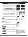
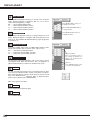
DISPLAY ADJUST
DISPLAY ADJUSTMENTS
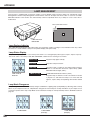
SCREEN ADJUSTMENTS
This projector has a picture screen resize function, which enables you to display desirable image size.
1
Press MENU button and ON-SCREEN MENU will appear. Press
POINT LEFT/RIGHT button(s) to move a red frame pointer to
DISPLAY ADJUST Menu icon.
2
Press POINT UP/DOWN button and move a red frame pointer to
Screen and then press SELECT button.
3
Press POINT UP/DOWN button to move a red arrow to level that
you want to set and then press SELECT button.
Full
Provides image to fit the horizontal size of the screen size.
Normal
Provides image in its original size.
Anamorphic
Provides image is forcibly changed to a 4:3 image, even if the input
signal is HDTV.
SCREEN ADJUSTMENT (DIRECT)
Select screen by pressing Screen button on Remote Control Unit.
Full
Normal
Anamorphic
Aspect H
Aspect V
These adjust the horizontal and vertical scale and position of the
screen. When a SELECT button is pressed, the mode changes to
Scale or Position adjustment mode. Use the POINT LEFT/RIGHT
button(s) to select whether you wish to adjust Scale or Position, and
then use the POINT UP/DOWN button(s) to adjust the values.
28
DISPLAY ADJUST MENU
DISPLAY ADJUST Menu icon
Set a red frame pointer
to item and press
SELECT button.
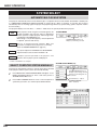
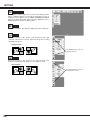
DISPLAY ADJUST
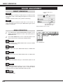
AUTO PC ADJUSTMENT
Auto PC Adjustment function is provided to automatically adjust Fine sync, Total dots and Picture Position to conform to your
computer. Auto PC Adjustment function can be operated as follows.
Auto PC Adj.
DISPLAY ADJUST MENU
1
Press MENU button and ON-SCREEN MENU will appear. Press
POINT LEFT/RIGHT button to move a red frame pointer to
DISPLAY ADJUST Menu icon.
2
Press POINT DOWN button to move a red frame pointer to
AUTO PC Adj. icon and then press SELECT button twice.
This Auto PC Adjustment can be also executed by pressing
AUTO PC ADJ. button on Side Control or on Remote Control
Unit.
DISPLAY ADJUST Menu icon
Set a red frame pointer
to item and press
SELECT button.
Store adjustment parameters.
Adjustment parameters from Auto PC Adjustment can be memorized
in this projector. Once parameters are memorized, setting can be
done just by selecting Mode in SYSTEM SELECT Menu (P26). Refer
to step 3 of MANUAL DISPLAY ADJUSTMENT section (P31).
NOTE
● Fine sync, Total dots and Picture Position of some computers can
not be fully adjusted with this Auto PC Adjustment function. When
image is not provided properly through this function, manual
adjustments are required. (Refer to page 30, 31.)
● Auto PC Adjustment function cannot be operated in Digital Signal
input on DVI terminal and “480i”, “575i”, “480p”, “575p”, “720p
(HDTV)”, “1035i (HDTV)”, “1080i/50 (HDTV)” or “1080i/60 (HDTV)”
is selected on SYSTEM SELECT Menu (P26).
29
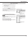
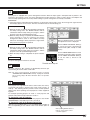
DISPLAY ADJUST
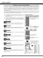
MANUAL DISPLAY ADJUSTMENTS
This projector can automatically tune to display signals from most computers and video equipments currently distributed.
However, some computers and video equipments employ special signal formats which are different from standard ones and
may not be tuned by Multi-Scan system of this projector. If this happens, projector cannot reproduce a proper image and
image may be recognized as a flickering picture, a non-synchronized picture, a non-centered picture or a skewed picture.
This projector has a Manual display adjustment to enable you to precisely adjust several parameters to match with those
special signal formats.
This projector has 20 independent memory areas {Mode 1~15 for video equipments and computers (digital signal), Mode 16
~ 20 for computers (analog signal)} to memorize those parameters manually adjusted. This enables you to recall setting for a
specific computer and video equipment whenever you use it.
1
Press MENU button and ON-SCREEN MENU will appear. Press
POINT LEFT/RIGHT button to move a red frame pointer to PC
ADJUST Menu icon.
2
Press POINT UP/DOWN button to move a red frame pointer to
item that you want to adjust and then press SELECT button.
Adjustment dialog box will appear. Press POINT LEFT/RIGHT
button to adjust value.
DISPLAY ADJUST MENU
DISPLAY ADJUST Menu icon
Move a red frame icon to item and
press SELECT button.
Fine sync
Adjusts an image as necessary to eliminate flicker from display.
Press POINT LEFT/RIGHT button to adjust value. (From 0 to 31.)
Total dots
Adjust the number of total dots in one horizontal period. Press
POINT LEFT/RIGHT button(s) and adjust number to match your PC
image.
Selected Mode
Shows status
(Stored / Free) of
selected Mode.
Horizontal
Adjusts horizontal picture position. Press POINT LEFT/RIGHT
button(s) to adjust position.
Vertical
Adjusts vertical picture position. Press POINT LEFT/RIGHT button(s)
to adjust position.
Press POINT LEFT/RIGHT
button to adjust value.
Press SELECT button at this icon to
display next items.
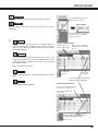
Display area
Selects area displayed with this projector. Select resolution at
Display area dialog box.
Press SELECT button at
Display area icon and Display
area dialog box appears.
Display area H
Display area
Adjustment of horizontal area displayed with this projector. Press
POINT LEFT/RIGHT button(s) to decrease/increase value and then
press SELECT button.
Display area V
Adjustment of vertical area displayed with this projector. Press
POINT LEFT/RIGHT button(s) to decrease/increase value and then
press SELECT button.
Press POINT LEFT/RIGHT
button to adjust value.
Press SELECT button at this
icon to display previous items.
30
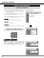
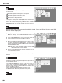
DISPLAY ADJUST
Current mode
Press SELECT button at this icon
to display previous items.
Press SELECT button to show information of computer selected.
Clamp
Current mode
Adjusts clamp position. When image has a dark bar(s), try this
adjustment.
Press SELECT button at Current
mode icon to show information of
computer connected.
3
Store
To store adjustment parameters, move a red frame pointer to
Store icon and then press SELECT button. Move a red arrow
pointer to any of Mode 1 to 20 that you want to store and then
press SELECT button.
To store adjustment data.
Terminal board and
System of input signal.
Shows values of “Total dots”
“Display area H” and “Display
area V”.
Mode free
To clear adjustment parameters previously set, move a red
frame pointer to Mode free icon and then SELECT button. Move
a red arrow pointer to Mode that you want to clear and then
press SELECT button.
Other icons operates as follows.
Reset
Reset all adjust parameters on adjustment dialog box to previous
figure.
Quit
Closes DISPLAY ADJUST MENU.
Vacant Mode
Store icon
Close this
dialog box.
Press POINT LEFT/RIGHT
buttons to display right page.
To clear adjustment data.
Shows values of scale and position
of “Aspect H” and “Aspect V” .
This Mode has parameters
being stored.
Press POINT UP/DOWN buttons
to display next/previous page.
Mode free icon
31
DISPLAY ADJUST
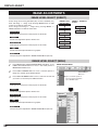
IMAGE ADJUSTMENTS
IMAGE LEVEL SELECT (DIRECT)
Select image level among Standard (AV), Cinema, Standard (PC),
Real and Image 1 ~ Image 10 by pressing IMAGE button on Side
Control or on Remote Control Unit.
Select image level Image 1 ~ Image 10 by pressing IMAGE 1 ~
IMAGE 10 buttons on Remote Control Unit.
Standard (AV)
Normal picture level preset on this projector for AV mode.
Cinema
IMAGE button
Standard (AV)
IMAGE 1 ~ IMAGE 10
buttons
Image 1
Cinema
Image 10
Standard (PC)
Real
Picture level adjusted for picture with fine tone.
Image 1
Standard (PC)
Normal picture level preset on this projector for PC mode.
Image 10
Real
Picture level with improved halftone for graphics.
IMAGE 1~10
User preset picture adjustment in IMAGE ADJUST Menu (P33, 34).
IMAGE LEVEL SELECT (MENU)
1
Press MENU button and ON-SCREEN MENU will appear. Press
POINT LEFT/RIGHT button to move a red frame pointer to
IMAGE ADJUST Menu icon.
2
Press POINT UP/DOWN button to move a red frame pointer to
image icon and then press SELECT button.
3
Press POINT UP/DOWN button to move a red arrow to level that
you want to set and then press SELECT button.
Standard (AV)
Normal picture level preset on this projector for AV mode.
Cinema
Picture level adjusted for picture with fine tone.
Standard (PC)
Normal picture level preset on this projector for PC mode.
Real
Picture level with improved halftone for graphics.
IMAGE 1~10
User preset picture adjustment in IMAGE ADJUST Menu (P33, 34).
32
IMAGE ADJUST MENU
IMAGE ADJUST
Menu icon
Move a red frame pointer to
item to be selected and then
press SELECT button.
DISPLAY ADJUST
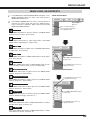
IMAGE LEVEL ADJUSTMENTS
1
Press MENU button and ON-SCREEN MENU will appear. Press
POINT LEFT/RIGHT buttons to move a red frame pointer to
IMAGE ADJUST Menu icon.
2
Press POINT UP/DOWN button to move a red frame pointer to
item that you want to adjust and then press SELECT button.
Level of each item is displayed. Adjust each level by pressing
POINT LEFT/RIGHT button(s).
Contrast
IMAGE ADJUST MENU
IMAGE ADJUST
Menu icon
Move a red frame pointer to
item to be selected and then
press SELECT button.
Press POINT LEFT button to decrease contrast, and POINT RIGHT
button to increase contrast. (From 0 to 63.)
Brightness
Press POINT LEFT button to adjust image darker, and POINT
RIGHT button to adjust brighter. (From 0 to 63.)
Color
Press POINT LEFT button to lighten color, and POINT RIGHT button
to deeper color. (From 0 to 63.)
Tint
Press POINT LEFT button or POINT RIGHT button to obtain proper
color. (From 0 to 63.)
Press POINT LEFT/RIGHT buttons
to adjust value.
Color temp.
Press either POINT LEFT button or POINT RIGHT button to Color
temp. level that you want to select. (XLow, Low, Mid or High)
Press SELECT button at this icon
to display next items.
White balance (Red)
Press POINT LEFT button to lighten red tone and POINT RIGHT
button to deeper tone. (From 0 to 63.)
White balance (Green)
Press POINT LEFT button to lighten green tone and POINT RIGHT
button to deeper tone. (From 0 to 63.)
Press SELECT button at this icon
to display previous items.
White balance (Blue)
Press POINT LEFT button to lighten blue tone and POINT RIGHT
button to deeper tone. (From 0 to 63.)
Sharpness
Press POINT LEFT/RIGHT buttons
to adjust value.
Press POINT LEFT button to soften the image, and POINT RIGHT
button to sharpen the image. (From 0 to 15.)
Detail enhancer
Press either POINT LEFT button or POINT RIGHT button to enhance
the detail of the image. (From 0 to 15.)
Press SELECT button at this icon
to display next items.
Gamma
Press either POINT LEFT button or POINT RIGHT button to obtain
better balance of contrast. (From 0 to 15.)
33
DISPLAY ADJUST
Noise reduction
Press POINT LEFT/RIGHT button(s) to change noise reduction
mode. Dialog box display is changed to “Off”, “L1”, “L2” or “L3” to
reduce noise (rough parts) of image.
Off ······· Noise reduction OFF position.
L1 ········ Noise reduction LEVEL 1 position.
L2 ········ Noise reduction LEVEL 2 position.
L3 ········ Noise reduction LEVEL 3 position.
Progressive scan
Press SELECT button at this icon
to display previous items.
Press POINT LEFT/RIGHT buttons
to change position.
Press SELECT button at this icon
to display first items.
Press POINT LEFT/RIGHT button(s) to change progressive scan
mode. Dialog box display is changed to “Off” and progressive scan
mode to off. Press POINT LEFT/RIGHT button(s) again, progressive
scan mode to on.
Auto picture control
Press either POINT LEFT button or POINT RIGHT button to Auto
picture control position that you want to select . (Off, L1 or L2)
Off ······· Auto picture control OFF position.
L1 ········ Auto picture control LEVEL 1 position.
L2 ········ Auto picture control LEVEL 2 position.
Auto lamp control
The projector reduce the brightness and set into the low power
consumption mode. When this function is “On”, the brightness is
adjusted automatically to a level that is suitable for the screen.
Store
To store manually preset image, move a red frame pointer to Store
icon and press SELECT button. Image Level Menu will appear.
Move a red frame pointer to Image 1 to 10 where you want to set and
then press SELECT button. Message "OK?" is displayed. Move
pointer to [Yes] and then press SELECT button.
Other icons operates as follows.
Reset
Reset all adjustment to previous figure.
Quit
Closes IMAGE MENU.
34
Image Level Menu
Move a red frame pointer to
any of Image 1 to 10 where you
want to set and then press
SELECT button.
Store icon
Press SELECT button at this
icon to store the adjustment.
SETTING
SETTING MENU
1
Press MENU button and ON-SCREEN MENU will appear. Press
POINT LEFT/RIGHT button(s) to move a red-frame pointer to
SETTING icon.
2
Press POINT DOWN button to move a red-frame pointer to item
that you want to set and then press SELECT button. Setting
dialog box appears.
Language
SETTING MENU
SETTING Menu icon
Set a red frame
pointer to item and
press SELECT
button.
Language used in ON-SCREEN MENU is selectable from among
English, German, French, Italian, Spanish, Portuguese, Dutch,
Swedish, Russian, Chinese, Korean and Japanese.
Lamp Mode
This Projector is equipped with 4 Projection Lamps and a number of
using lamps can be switched to 4 lamps or 2 lamps. Using 2 lamps
maintain life of Projection Lamps.
To change over Lamp Mode
1. Press MENU button and ON-SCREEN MENU will appear. Press
POINT LEFT/RIGHT buttons to select SETTING and press
SELECT button. Setting dialog box appears.
2. Press POINT DOWN button to move a red frame pointer to
“Lamp mode”. Set "4 lamps mode" or "2 lamps mode" by
pressing POINT LEFT/RIGHT button(s). When Lamp Mode is
set from "4 lamps mode" to "2 lamps mode" image becomes little
darker. When Lamp Mode is set from "2 lamps mode" to "4
lamps mode" image become brighter gradually.
When pressing SELECT
button at Language,
Language Menu appears.
Blue back
When this function is “On,” this projector will produce a blue image
instead of the video noise on the screen when any input source is
unplugged or turned off.
Display
Move a pointer to item Optional Control
and then press POINT Refer to page 11.
LEFT/RIGHT button(s).
Number
This function decides whether to display On-Screen Displays.
On ··· Shows all the On-Screen Displays.
Off ··· Sets On-Screen Displays disappeared except;
● ON-SCREEN MENU
● “Power off?” message
● P-TIMER
● “No signal” message
● “Wait a moment” message
Menu size
This function decides to display On-Screen Displays size.
Normal ··· Shows normal size the On-Screen Displays.
Double ··· Shows double size the On-Screen Displays.
35
SETTING
Menu position
This function is used to adjust the on-screen menu display position.
When a SELECT button is pressed, the adjustment screen is
displayed (arrows appear). Use the POINT UP/DOWN/LEFT/RIGHT
button(s) to adjust the position. After making the adjustment, press a
SELECT button to return to the Menu screen.
Logo
When this function is “On,” projector displays logo when starting up.
Ceiling
When this function is “On,” picture is top / bottom and left / right
reversed. This function is used to project the image from a ceiling
mounting the projector.
Ceiling function
Press SELECT button at this icon
to display next items.
Rear
When this function is “On,” picture is left / right reversed. This
function is used to project the image to a rear projection screen.
Rear function
Press SELECT button at this icon
to display previous items.
36
SETTING
Power management
This projector is equipped with a power management function. When the input signal is interrupted and any button is not
pressed for 30 seconds or more, the power management function operates in order to reduce power consumption and
conserve lamp operating time. The factory default settings for power management are "Ready" and "5 Min".
OPERATION
1) If the input signal is interrupted and any button is not pressed for 30 seconds or more, the message "No signal" and the
timer display appears on the screen. Then the count-down starts for the time being set.
If "Ready" is selected
2) When the set time is elapsed, the lamp will be switched off
and lamp cooling starts. The READY indicator will be
switched off while the lamp cooling is in progress, and the
projector cannot be operated during this time.
3) When the lamp cooling is completed, the READY indicator
starts flashing to notify the operator that power
management mode is active. In this condition, the lamp
will turn on and images will be projected if a signal starts
being input or the projector is operated.
When a SELECT button is pressed,
the adjustment screen is displayed.
If "Shut down" is selected
Use the POINT LEFT/RIGHT button(s)
to select the power management
function mode ("Off", "Ready" or "Shut
down").
2) When the set time is elapsed, the lamp will be switched off
and lamp cooling starts. The READY indicator will be
switched off while the lamp cooling is in progress, and the
projector cannot be operated during this time.
3) When the lamp cooling is completed, the power switches
off.
Use the POINT DOWN button to move
the pointer to the time setting, and then
use the POINT LEFT/RIGHT button(s)
to set the time (1 minute to 30
minutes).
If "Off" is selected
The power management function is canceled.
Time left until Lamp off.
On start
When this function is “On,” projector is automatically turned on just
by connecting AC Power cord to a wall outlet.
Note ; Be sure to turn projector off properly (refer to section
“TURNING OFF PROJECTOR” on P22). If projector is turned
off in wrong steps, On Start function does not operate
properly.
Remote control
This projector has eight different remote control codes; the factoryset normal code (Code 1) and the other seven codes (Code 2 to
Code 8). This switching function prevents remote control operation
mixture (jam) when operating several projectors or video equipment
together.
For example operating projector in “Code 7,” both projector and
Remote Control Unit must be sw