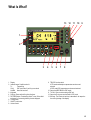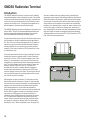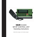
1
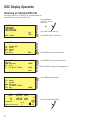
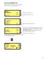
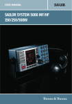
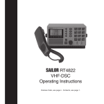
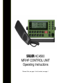
SAILOR HC4500 MF/HF CONTROL UNIT Operating Instructions Distress Calls, see page ii. List of contents, see page 1. Quick DISTRESS Call 1. If off or STANDBY: press ON/OFF. 2. Open DISTRESS lid. 3. Press DISTRESS until RELEASE is displayed 3-2-1RELEASE Then the undesignated distress call will be sent by default on the distress frequency 2187.5 kHz. Press the DISTRESS button for 3 seconds to transmit TYPE MSG. Pos Time : Distress : Undesignated : N57°01 W009°53 : 13:01 UTC Awaiting Automatic Repetition Wait for answer! Rx Tx CANCEL 2182.0 kHz 2182.0 kHz SSB TELEPHONY (The distress call is autorepeated every 5 minutes on the same distress frequency.) POWER HIGH SQUELCH ON CANCEL MODE TUNE< CLRF RF-G SIGNAL ||||| DISTRESS Acknowledgement Distress acknowledgement received VIEW FROM: 002191000 4. Press VIEW to read the contents of call. ABORT Read call contents. 5. Press “2182”. DISTRESS Rx/Tx 2182.0 kHz 6. Lift handset. ii FREQ MODE AM TELEPHONY Press PTT and say: Press CH POWER HIGH SIGNAL ||||| “MAYDAY, MAYDAY, MAYDAY This is <Ship name (3 times)> MAYDAY This is <Ship name + call sign> Position: ... What is wrong: ... Kind of assistance: ... Number of crew: ... Other info: ... OVER.” Release Listen for answer! BAND What Is What? 13 12 11 10 9 1 2 3 1. Display. 2. Indicator lamps. Condition when lit: Tx: Transmitting. CALL: DSC (see button 9) call for you received. ALARM: Alarm call received. 3. Keyboard. 4. Shift key. Press and hold for yellow functions. 5. DISTRESS button. Protected by shield. To use, lift the shield and press for 3 seconds, guided by the text displayed. 6. Tuning control. 7. ON/OFF push button. 8. Volume control. 4 5 6 7 8 9. TEL/DSC function switch. In TEL mode radiotelephone parameters are shown and selected. In DSC mode DSC parameters are shown and selected. 10. Opens the ADDR BOOK in DSC mode. 11. Tx CALL: Press to start creating a DSC call. 12. Opens the Rx log over received calls in DSC mode. 13. Soft keys. The function of each key is described in its respective line at the right edge of the display. iii Introduction Congratulations on your new SAILOR HC4500 MF/HF maritime radio telephone with built-in DSC (Digital Selective Calling) system and radiotelex, fulfilling the highest international standards for marine MF/HF communication and safety procedures. For an explanation of DSC, see page 2. Your SAILOR HC4500 MF/HF is a part of the modular system 4000 which also includes a HF single sideband radiotelephone. It has built-in MF/HF telex if connected to a PC and/or a printer. If connected to a GPS or other maritime navigation system it can automatically include the true UTC time and your position in its DSC distress messages. SAILOR marine equipment is specially designed for the extremely rugged conditions on bord a ship, based on more than 50 years’ experience with all kinds of boats, from small pleasure crafts, over fishing boats working under all climatic conditions, to the biggest ships. S.P. Radio A/S is one of Europe’s leading manufacturers of maritime radiocommunication equipment - a position which has been maintained by means of constant and extensive product development. We have a worldwide network of dealers with general agencies in more than fifty countries. All our dealers are specially trained to service all your SAILOR products. About this manual This manual is for the daily user of the system. Additionally, it includes a section on the installation procedures, and - on page ii standard distress procedures. We highly recommend you to read the manual before you start using the equipment. Please note Any responsibility or liability for loss or damage in connection with the use of this product and the accompanying documentation is disclaimed. The information in this manual is furnished for informational use only, is subject to change without notice, may contain errors or inaccuracies, and represents no commitment whatsoever. This agreement is governed by the laws of Denmark. Document no.: B4500GB0 iv C/9923 Abbreviations Used in this Manual ADDR AGC AM ARQ CLRF CU DIRTLX DSC ETSI FEC GA GMDSS GPS HF IMO IRS ISS ITU MF MMSI MOM MSG NBPD PTT RF-G Rx SSB TEL Tx UTC VHF Address Automatic Gain Control Amplitude Modulation Automatic Repetition reQuest Clarify Control Unit Direct Telex Digital Selective Calling European Telecommunications Standards Institute Forward Error Correction Go Ahead Global Maritime Distress and Safety System Global Positioning System High Frequency International Maritime Organisation Information Receiving Station Information Sending Station International Telecommunication Union Medium Frequency Maritime Mobile Ship Identification Just a moment please Message Narrow Band Direct Printing Push-To-Talk Receiver Frequency Gain Receive Single Side Band Telephony Transmit Co-ordinated Universal Time Very High Frequency Contents Quick DISTRESS Call .......................................................... ii DISTRESS Acknowledgement ............................................ ii What Is What? ..................................................................... iii Introduction ......................................................................... iv About this Manual .............................................................. iv Abbreviations ...................................................................... iv MF/HF Fundamental Info .................................................... 2 Propagation of MF and HF Radio Waves. ....................... 2 Radiotelephony ................................................................ 2 Radiotelex ........................................................................ 2 DSC .................................................................................. 2 Basic Functions ................................................................... 3 Switching ON/OFF ........................................................... 3 Setting Backlight Level .................................................... 3 Switching Loudspeaker ON/OFF ..................................... 3 Volume Control ................................................................ 3 Switching Squelch ON/OFF ............................................. 3 Setting Transmitter Power Level ...................................... 3 Manual Call Functions ........................................................ 4 Telephony Channel Display Functions: ........................... 4 Frequency Display Functions: ......................................... 4 Tuning .............................................................................. 4 Station Display Functions: ............................................... 5 Distress Telephony Frequencies ..................................... 5 Distress Frequency Display Functions: ........................... 5 Two-tone Alarm Signal ........................................................ 6 Two-tone Alarm Display Functions: ................................. 6 Listening for Calls ............................................................... 6 Making a Manual Call .......................................................... 6 DSC Main Buttons ............................................................... 7 DSC Display Operation ....................................................... 8 Receiving an Individual DSC Call .................................... 8 Receiving DISTRESS Call ............................................... 9 Calling a SHIP ................................................................ 10 Calling a SHORE Station ................................................ 11 Address Book ................................................................. 12 Using Two Control Units ................................................ 13 Priority of Control Unit #1 ......................................... 13 Control Unit #2 Taking Over the Control .................. 13 Status Indication ....................................................... 13 Responding to Incoming DSC Calls ........................ 13 Power On/Off By Control Unit #2 ............................. 13 Interconnecting ......................................................... 13 DSC Scanning Frequencies ..................................... 13 Advanced DSC Calls ......................................................... 14 Changing a Function ...................................................... 16 The Function Tree .................................................... 17 GMDSS Radiotelex Terminal ............................................ 18 Introduction .................................................................... 18 Keyboard Indicator Lamps ............................................. 19 Keyboard Function Keys ................................................ 19 Switching On .................................................................. 20 Channel Selection .......................................................... 20 Transmitting a Message ................................................. 20 Editing a Message ......................................................... 20 Receiving a Message ..................................................... 21 Installation and Initial Set-up ......................................... 21 Printer ....................................................................... 21 Keyboard .................................................................. 21 Modem Set-up .......................................................... 21 Example of FEC Transmission ...................................... 22 Example of ARQ Transmission to a Coast Statio .......... 22 1 MF/HF Fundamental Info Propagation of MF and HF Radio Waves. MF/HF radiocommunications provide a medium and long range service. The 1.6-4 MHz marine band is intended primarily for coastal operation beyond normal VHF communication range. A reliable range of more than 150 nautical miles can be expected in most areas in the daytime, more in the nighttime. Propagation of the radio waves in this band is mainly by ground waves i.e. the waves from the transmitter aerial follow the earth’s curvature to the receiver aerial. The high frequency range 4 - 30 MHz can provide communication for hundreds or even thousands of nautical miles. The long range is achieved by sky waves reflected from the ionosphere. Propagation of the radio waves depends on a number of factors such as frequency, time of day, time of year, and solar activity. The channels allocated to the maritime mobile service in the HF range are divided into a number of bands: 4, 6, 8, 12, 16, 18, 22, 25 MHz to allow a suitable frequency band to be selected for communication dependent on distance and time of day. Radiotelephony The mode of emission used for telephony transmissions in the marine bands is SSB (single-sideband, J3E). On the international distress frequency 2182 kHz compatible AM (amplitude modulation, H3E) may be used in addition for communication with non-GMDSS ships. AM mode is used also when receiving broadcasting. The frequencies for radiotelephone distress and safety traffic in the HF bands are 4125 kHz, 6215 kHz, 8291 kHz, 12290 kHz, and 16420 kHz. Working frequencies for public correspondence with coast stations are arranged in pairs for duplex/semi-duplex operation. For the HF bands these channels are allocated numbers by ITU on an international basis. In addition a number of simplex frequencies are available in each band for ship-to-ship communication. Radiotelex Marine telex is also referred to as ‘Narrow Band Direct Printing’ (NBDP). Due to the narrow bandwidth of the transmissions, a longer range may be expected compared to radiotelephony. The frequencies for radiotelex distress and safety traffic are 2174.5 kHz, 4177.5 kHz, 6268 kHz, 8376.5 kHz, 12520 kHz, and 16695 kHz. Working frequencies for public correspondence with coast stations are arranged in pairs. For the HF bands these channels are allocated numbers by ITU on an international basis. In addition a number of simplex frequencies are available in each band for ship-to-ship communication. 2 DSC DSC (Digital Selective Calling) is an automatic calling system which allows a specific station to be contacted and made aware that a station wishes to communicate with it. In addition to calls to specific stations the system can also be used to call ‘all ships’ and groups of ships and this is of significance for its use for DSC distress alerting. DSC is an alerting signal only and the communication which follows the call is made on an appropriate frequency band using radiotelephony or radiotelex. The frequencies for DSC distress and safety calling are 2187.5 kHz, 4207.5 kHz, 6312 kHz, 8414.5 kHz, 12577 kHz, and 16804.5 kHz. Calling frequencies for public correspondence with coast stations are arranged in pairs, both international and national frequencies are assigned. In addition the frequency 2177 kHz may be used for ship-to-ship calling. Basic Functions Setting Transmitter Power Level 1. Press the Shift key followed by the Power Key. Switching ON/OFF 1. Press the ON/OFF button. The output power is set to HIGH, MED or LOW. Repeat until the desired setting is reached. Setting Backlight Level 1. Press the Shift key followed by the DIM key. The backlight is changed from zero to maximum in four steps. Repeat until the desired setting is reached. Switching Loudspeaker ON/OFF 1. Press the Shift key followed by the SPK key. Volume Control 1. Rotate the VOL button to adjust the loudspeaker sound volume. Switching Squelch ON/OFF (SSB Telephony mode) 1. Press the Shift key followed by the Squelch key. When squelch is ON, the receiver output is muted in speech pauses. 3 Manual Call Functions Telephony Channel Display Functions: Name of station if selected. Channel number. LYNGBY Soft keys FREQ CH 418 SSB TELEPHONY POWER HIGH SQUELCH ON CH SIGNAL ||||| Squelch setting Mode of emission Output power setting STATION Switches to Frequency display for viewing or altering frequencies. Switches to Station display for selection of another station. Steps to the next lower channel number of the station. Steps to the next higher channel number of the station. Receive: Signal strength Transmit: Output power level A channel number may also be keyed in directly from the keyboard. If the channel is not allocated to the station selected, the station name will disappear from the display. Frequency Display Functions: Receive frequency Transmit frequency > Rx Tx 4357.0 kHz 4065.0 kHz MODE SIGNAL ||||| TUNE< CLRF RF-G SSB TELEPHONY POWER HIGH SQUELCH ON Squelch setting Mode of emission Output power setting Soft keys CH Switches to Channel display and previous channel number. TX Moves the arrow to Tx before keying in a Tx frequency. Steps between SSB telephony, AM telephony and Telex mode. Steps between Tune, Clarify and RF-Gain tuning functions. Receive: Signal strength Transmit: Output power level Rx frequencies may be keyed in directly from the keyboard Tuning (Frequency display only) 1. Rotate the TUNE button to adjust frequency or RF-gain of the receiver. Functions indicated by arrow in the Frequency display: TUNE: Frequency tuning in 1 kHz steps (AM), 100 Hz steps (SSB) or 500Hz (Telex). CLFR: Frequency tuning in 10 Hz steps. RF-G: Manual RF-gain tuning, AGC off. 4 Station Display Functions: Name of station MMSI number of station STATION TABLE NAME CALL SIGN MMSI NO TELEX NO Soft keys SELECT Selects the station and switches to Channel display for choice of channel number. CANCEL Returns to Channel display without selecting the station. LYNGBY OXZ 002191000 37383 STN Selects previous station. Selects next station. Telex call code Distress Telephony Frequencies To switch to Distress Frequency display: Press 2182 Distress Freq key. Distress Frequency Display Functions: Receive/transmit frequency. DISTRESS Rx/Tx 2182.0 kHz AM TELEPHONY POWER HIGH SQUELCH OFF Mode of emission Output power setting SIGNAL ||||| Soft keys CH Switches to Channel display and previous channel number. FREQ Switches to Frequency display. MODE Selects between AM and SSB mode of emission on 2182 kHz. BAND Steps to the distress telephony frequency in the next higher band. Receive: Signal strength Transmit: Output power level The frequencies for distress and safety telephony traffic are 2182 kHz, 4125 kHz, 6215 kHz, 8291 kHz, 12290 kHz, 16420 kHz 5 Two-tone Alarm Signal To switch to the Two Tone Alarm Signal display: Press the Shift key followed by the Alarm key. Two-tone Alarm Display Functions: Soft keys Press the START button 5 seconds to send alarm FREQ Returns to frequency display. TEST Starts test of the alarm signal generator. START Starts transmission of the two tone alarm signal. Transmission of the two tone alarm signal will continue for 45 seconds, but may be stopped manually by pressing the STOP key in the frequency display. When the alarm signal ceases press the handset key and transmit your distress message by speaking into the handset microphone with a clear and calm voice. Note: The two tone alarm signal generator is intended for alerting ships not yet equipped with DSC equipment. It may be used only to announce a distress message and primarily on the frequency 2182 kHz in AM telephony mode. Listening for Calls Making a Manual Call Coast stations transmit traffic lists consisting of call signs/names of the ships for which they have traffic. The traffic lists are sent at specified times and at intervals of typically two hours. They are broadcasted on the normal working frequencies on the coast station. Ships should, as far as possible, listen to the traffic lists transmitted by relevant coast stations. On hearing their call sign they should establish communication as soon as they can do so. Wait until transmission of the traffic list has finished and the channel is free. Call the coast station on the working frequency on which the traffic list was received or as instructed by the coast station. 1. Select the appropriate station. 2. Select the channel on which traffic lists are transmitted. 3. Switch loudspeaker on and adjust volume to an appropriate level. If on HF, traffic lists are transmitted in more frequency bands simultaneously, search for the channel with the best propagation conditions. 6 1. Hook off the handset. 2. Press the PTT key on the handset when speaking. Say: 1. <Called station’s name (3 times)> 2. ‘This is’ <Your ship’s name (3 times)> 3. ‘Over’ 3. Release the PTT key to listen. 4. When answered: Follow the instructions from the coast station. The coast station may ask for further identification, information on position and next port of call, and may suggest another working channel for the traffic to follow. If the coast station is not ready to receive traffic immediately it may ask you to wait for a specific number of minutes. DSC Main Buttons To switch between the DSC STATUS and telephony displays: press TEL/DSC. Soft keys DSC STATUS Distress Watch: 2 Calling Watch: 2 4 2 6 1 CHANGE Changes calling watch frequencies. WATCH Switches between calling watch On/Off 8 1 12 16 MHz 4 -- MHz VIEW FREQ Distress Frequency: 2187.5kHz DIST. FREQ Views watch frequencies. Changes distress frequency used default for quick distress calls. DSC STATUS display LYNGBY FREQ CH SSB TELEPHONY POWER HIGH SQUELCH ON 418 SIGNAL ||||| STATION CH Telephony Display The button opens to the screen menu where all DSC calls are stored. In this menu NORMAL or DISTRESS calls, can be read separately and sorted by time. The button opens the Address book menu. An addr book call is a complete DSC call added a name. It is possible to transmit, add or delete calls from here. The button opens to the DSC transmitter menu. From here it is possible to make very easy calls. (SHORE, SHIP) and more complicated calls including special category and tele commands. The button switches between the DSC STATUS and telephony displays. The MF/HF set is equipped with two receivers. One for watch on the distress frequencies and one for watch on the public DSC frequencies (calling watch). The calling watch receiver is identical with the receiver of the radio, and therefore it is possible to switch the calling watch on and off. The calling watch is only active in DSC mode, i e. calling watch is automatically switched off when switching to the TEL screen. But if calling watch is on and the user hooks on the handset, the control unit will automatically switch to the DSC status menu. 7 DSC Display Operation Receiving an Individual DSC Call When calling watch is on, your MF/HF set is constantly scanning the selected DSC channels for incoming DSC calls. Lift the handset and press PTT to connect to the caller. Lift HANDSET to connect OR Individual call received Press VIEW to read out the call. VIEW ABORT FROM: 219000012 Press ABORT to return to TEL screen. CALL CONTENT Time TYPE: FROM: CAT.: ACKN: 10:55:00 13 Okt 97 Individual 219000012 Routine Request Select CONNECT to reply call COMM: SSB telephony MSG.: No Info AD.: Freq. RX 2053.0 TX 2053.0 MORE Press MORE to view the second part of call. CONNECT Press CONNECT to transmit and set channel. CHANGE Press CHANGE to change the acknowledgement. CANCEL AGAIN Select send to transmit SEND TYPE: TO : COMM: AD.: ACKN: CANCEL Individual 219000012 SSB telephony Freq. RX 2053.0 TX 2053.0 Reply > Rx Tx 2053.0 kHz 2053.0 kHz MODE SIGNAL ||||| TUNE< CLRF RF-G SSB TELEPHONY POWER HIGH SQUELCH OFF 8 Press SEND to transmit the reply. CH TX Take the handset and start talking. Receiving DISTRESS Call When switches on your MF/HF set is constantly scanning all DSC distress channels for incoming DSC distress calls. Distress call received VIEW Press VIEW to read out the call. ABORT Press ABORT to return to TEL screen Time: 08:55:00 22 Sep 97 . TYPE: Distress FROM: 219001000 MSG.: Fire Received on 2187.5 kHz MORE Press MORE to view the second part of call. CALL CONTENT ACK/REPLY Press ACK/REPLY to send distress acknowledgement or distress relay. In these menus there is a security that makes it impossible to send an acknowledgement by mistake. Press SETUP to return to the TEL screen with the appropriate radio distress frequency, in this case 2182 kHz. FROM: 21900100 CALL CONTENT SET UP N: 57°01 E:009°52 Time 09:58 UTC COMM: SSB Telephony CANCEL AGAIN Press AGAIN to view the first part of call. If the ship in distress is within a reachable distance press “2182” and listen to the subsequent information. DISTRESS Rx/Tx 2182.0 kHz AM TELEPHONY POWER HIGH SQUELCH OFF SIGNAL ||||| CH FREQ MODE BAND 9 Calling a SHIP Press Tx CALL SHORE Select type of call: SHIP Select a SHIP call. DISTRESS MORE Key in the nine digit MMSI number of the wanted ship. Key in the ship MMSI number ACCEPT < MEMORY TYPE: TO : Individual 210215456 Accept the number. A sub menu where a pre-programmed ship can be selected. CANCEL The current telephony frequency is included in the call, and this frequency is used as working frequency for the following radio communication. Select DSC frequency Rx Tx 2177.0 kHz 2177.0 kHz ACCEPT CANCEL Select send to transmit SEND TYPE: TO : COMM: AD.: ACKN: CANCEL Individual 210215456 SSB telephony Freq. RX 2053.0 TX 2053.0 Request Select the frequency on which the call is transmitted. Select SEND to transmit the call. You first see the messages “Call in progress” and then “Waiting for acknowledgement” Wait for answer If the ship answers, see page 8 Receiving an Individual DSC call. 10 Calling a SHORE Station Press Tx CALL SHORE Select type of call: Select a SHORE call. SHIP DISTRESS MORE Key in the nine digit MMSI number of the wanted coast station. Key in the coast station MMSI number ACCEPT < MEMORY TYPE: TO : Accept the number. Individual 002191000 A sub menu where a preprogrammed station can be selected. CANCEL If the SHORE station supports the possibility of including a telephone number, the telephone number can be keyed in followed by ACCEPT. Key in the phone number TYPE: TO : ACCEPT < Individual LYNGBY _ TEST CALL Select TEST CALL to make a test call to the coast station. CANCEL Select DSC frequency Rx Tx Select ACCEPT to make a call directly to the shore station and talk with a person there if no phone number is keyed in. 8049.0 8049.0 ACCEPT kHz kHz Select the frequency on which the call is transmitted. CANCEL Select send to transmit SEND Select SEND to transmit the call. TYPE: TO : AD.: ACKN: CANCEL You first see the messages “Call in progress” and then “Waiting for acknowledgement” Wait for answer Individual LYNGBY No info Request Note that when calling a coast station, it is always the coast status that selects the working frequency for the following communication. If the coast station answers see page 8 Receiving an Individual DSC call. 11 Address Book This MF/HF set is designed with self explaining menues. The four soft keys on the right side of the display refer to the display text. Open the addr book menu. Lower left side of the display is the data area. Right side shows the function of the soft keys. Upper left side of the display is used for text instructions ^ Use ^, or keyboard to search in addr book Ms Sunrise TO : MSG : 219222222 No info Select ADD to make a new call ACCEPT Accepts the data. NAME MORE Go to the next screen on the same subject. ADD DELETE One step back. CANCEL AGAIN 12 Go to the first screen on the same subject. Using Two Control Units You can connect two control units to the system. However, it can only be controlled by one control unit at a time. If for instance control unit #2 has sent an individual DSC call, control unit #2 is to receive and respond to the acknowledgement call that may follow. If a call comes in when both control units are in the DSC Status Menu, and therefore not active, both control units are to receive and respond to the call. Priority of Control Unit #1 Control unit #1 has the highest priority, i.e. you can always control the system by means of control unit #1 – even if control unit #2 has initiated a distress call. Control Unit #2 Taking Over the Control When control unit #1 is in the DSC Status Menu, control unit #2 can take over the control of the system by leaving the DSC Status Menu. When control unit #2 returns to the DSC Status Menu, the control is automatically given back to control unit #1. Power On/Off By Control Unit #2 Power On You can turn on the whole system by means of control unit #2. If the display shows the words “Unit switched off”, and the on/off button is pressed, what happens depends on whether or not control unit #1 is controlling the system at the moment: a) If control unit #1 is controlling the system, this will be indicated by the display of control unit #2. b) If control unit #1 is not controlling the system, control unit #2 will start up in the DSC Status Menu. Status Indication Control Unit #1: When control unit #2 controls the system, the display of control unit #1 shows what activity is taking place. The following read-outs may appear: • ”OCC by unit 2 sending Distress alert” means that control unit #2 is transmitting a distress call, or awaiting automatic retransmission. • “OCC by unit 2 sending DSC call” means that control unit #2 is transmitting an ordinary DSC call. • “OCC by unit 2 using DSC functions” means that control unit #2 is in a DSC menu without transmitting a call. • “OCC by unit 2 using Radio functions” means that control unit #2 is not in a DSC menu. Control Unit #2: The display of control unit #2 always shows when the system is busy. When the system is not busy, the display shows the DSC Status Menu. If control unit #2 tries to take over the control, but is not allowed to do so, this is indicated by both a sound and the display read-out “OCC by unit 1”. Responding to Incoming DSC Calls When a call comes in, only the active control unit – i.e. the one that controls the system at the moment – is to respond. When the whole system is off, it makes no difference which control unit turns it on. Power Off You cannot turn off the whole system by means of control unit #2. When you press the on/off button, only control unit #2 is turned off. The display will then show the words “Unit switched off”. Interconnecting When you have received a DSC call, including working frequency, it is possible to transfer the system control from control unit #1 to control unit #2. To do so, in the Frequency menu, key: “Shift” + “INTC/InterCom”. When a DSC call is transferred from control unit #1 to control unit #2, the right working frequencies are maintained. If the handset of control unit #2 is not lifted within five minutes, the control automatically returns to control unit #1. DSC Scanning Frequencies You cannot change the DSC scanning frequencies by means of control unit #2. The scanning frequencies used when in the DSC Status Menu of control unit #2 are the same as if in the DSC Status Menu of control unit #1. If control unit #1 changes the DSC scanning frequencies, that information is passed on to control unit #2. Therefore, if control unit #2 is given the control, and starts scanning, the same scanning frequencies are used. 13 Advanced DSC Calls Extended DSC calls make it possible for you to control the call completely within the international rules, including the possibility of sending data or fax from optional equipment connected to your MF/ HF set. To start an extended call, select EXTENDED as the ‘Type of call’ in the Tx menu below, and then continue in the Extended calls menu on next page. If you have selected an INDIVIDUAL Ship, GROUP, or Group AREA call, all your options are the same after having selected the address. Please observe the international rules for the rights to forward DISTRESS RELAY calls. Tx menu. Enter correct data instead of examples shown in italics:: Type of call Address Options Other data transmitted SHORE Shore: Shore Phone: 00 1234567 or from ADDR.BOOK 123456789 No info: Call shore station 98765432 : Call Phone No. Test call (none) Routine - SSB Routine - SSB Safety - Test Routine - SSB frequency SHIP LAST CALL DISTRESS EXTENDED 14 Repeat the last call made. UNDESIGNATED DISABLE SINKING LISTING (CAPSIZE) GROUNDING COLLISION FLOODING FIRE ABANDONING PIRACY MAN OVER BOARD EPIRB (See next page) Telecom 1 telephony - No Info telephony - <Phone number> No info telephony - No Info - Work Position UTC time for position ... to be entered manually if not obtained from e.g. a GPS. Ackn. Yes Yes Yes SSB telephony AM telehony FEC ? EXTENDED Tx call started from “EXTENDED” in the table on the previous page. Enter correct data instead of examples shown in italics: Type of call Address Options INDIVIDUAL Shore: Shore phone: Ship: GROUP G.AREA 001234567 No info: Call shore station Routine 98765432: Call Phone No. Routine Category 123456789 012345678 N:57° d02° W:009° d03° The data in the example gives the area: N:55..57° W:6..9° Telecom 1 Telecom 2 SSB telephony SSB telephony SSB telephony AM telephony POLLING No info No info No info MEDICAL AIRCRAFT No info FAX ARQ FEC TTY RX TTY TAPE MORSE SHIP POSITION DATA No info DISTRESS RELAY DISTRESS ACK Type of address Address ALL SHIPS All ships INDIVIDUAL 001234567 Type of Address address ALL SHIPS All ships Ship in distress DISTRESS SAFETY URGENCY Distressed Distress ship’s MMSI relay UNKNOWN KNOWN 123456789 Distressed ship’s MMSI 123456789 Distress ack No info Position Work. frequency Same as above As for DISTRESS As for DISTRESS As for DISTRESS in table Tx Call As for DISTRESS in table Tx Call As for DISTRESS in table Tx Call As for DISTRESS in table Tx Call in table Tx Call in table Tx Call Unable to comply Ackn. Yes V21 V22 V22 BIS V23 V26 V26 BIS V26 TER V28 TER V32 No reason Congestion Busy Queue Station Barred No operator Temporary engaged Equipment not No channel No mode No info Same as Work. above frequency ROUTINE URGENCY DISTRESS SAFETY BUSINESS ALL SHIPS Add. msg. Yes No No MMSI address rule: Shore station numbers start with 00, group numbers start with one 0, ship numbers start with a digit 1-9. 15 Changing a Function There are a large number of function settings available, selectable from a function tree, see the next page. This chapter only deals with the principles of how to use the function tree. An example: Changing the Display Contrast Press SHIFT and FUNC to enter function menu. USER Select function or group of settings Select the USER functions. TELEPHONY DSC MORE DISPLAY Select type of general user functions Select DISPLAY. SOUND VERSION MORE ^ Use ^, to change value Contrast: ACCEPT 6 Use ^ and v to change the contrast value. CANCEL 16 The Function Tree 0HQX 8VHU 6XEPHQX/HYHO 'LVSOD\ 6RXQG 9HUVLRQ 3ULQW'6& &RQILJ 0HQX 7HOHSKRQ\ 6XEPHQX/HYHO &+ 3URWHFWLRQ 7HVW 0HQX '6& 6XEPHQX/HYHO 006, $&.1 '6&)UHT 3RVLWLRQ 7LPH 7HVW /DQJXDJH 0HQX 6WDWLRQ 6XEPHQX/HYHO $GG 'HOHWH 9LHZ(GLW 6XEPHQX/HYHO &RQWUDVW (DUSLHFHOHYHO $ODUPOHYHO 3DUDPHWHUV WR+LJK&RQWUDVW $WWHQXDWLRQ/HYHO $WWHQXDWLRQ/HYHO 6:YHUVLRQVIRUDOOPRGXOHV 3ULQWHU2Q2II +:FRQILJXUDWLRQ 6XEPHQX/HYHO $GG 'HOHWH 9LHZ 3DUDPHWHUV $GGQHZXVHUFK 'HOHWHXVHUFK 9LHZFK 5HDG7UDQVFHLYHUSURWHFWLRQFRGHV 6HOIWHVW78PRGXOH 6XEPHQX/HYHO 3DUDPHWHUV 7KH006,QXPEHURIWKHXQLW $XWRDFNQRQUHTXHVW2Q2II $GGQHZ'6&FDOOUHFHLYHIUHT 'HOHWH'6&FDOOUHFHLYHIUHT 9LHZ'6&FDOOUHFHLYHIUHT $XWRPDWLFLIFRQQHFWHGWRD*36 $XWRPDWLFLIFRQQHFWHGWRD*36 '6&PRGHPVHOIWHVW &KDQJHODQJXDJHLIDOORZHG $GG 'HOHWH 9LHZ &KDQJH &KDQJH 6XEPHQX/HYHO 6KRUH 6KLS 3DUDPHWHUV $GGQHZVKRUHVWDWLRQ $GGQHZVKLSVWDWLRQ 'HOHWHVWDWLRQ 9LHZVWDWLRQVRU(GLWVWDWLRQV Options: System settings. For authorized service personnel only. 17 GMDSS Radiotelex Terminal Introduction The GMDSS Radiotelex Terminal is an option used for handling transmission/reception of telex messages over radio. The terminal consists of a printer and a keyboard, connected to the transceiver control unit which provides the interface to the DSC/telex modem located in the transceiver unit. The keyboard is equipped with an affixed template for function keys and indicator lamps. The GMDSS Radiotelex Terminal was designed in accordance with relevant IMO, ITU and ETSI recommendation/specifications and has been approved for shipboard installations to be operating within the Global Maritime Distress and Safety System. It supports world-wide ship-to-ship, shore-to-ship and ship-to-shore communication by utilizing the radiotelex protocols described in ITU- Rec. 625 to overcome the deficiencies of the HF medium. In case of two-way communication an ARQ (Automatic Repetition reQuest) algorithm for error correction is thus used, and when sending to more than one station an FEC (Forward Error Correction) algorithm is used. To facilitate error detection the source text consisting of 5-bit telex characters is coded to a constant weight (3/4 ratio of mark and space bits) 7-bit code. In FEC mode the message is sent in time diversity i.e. each character is sent twice with a time interval by interleaving the original character stream with a delayed version of itself. The receiving station thus has two chances to receive the character correctly. If both are in error a ‘*’ is printed. FEC broadcast calls are used for sending collective messages to several stations simultaneously. A special class of FEC allows selective calling by means of call codes. The message is transmitted in inverted format and only receiving stations with the correct call codes will receive the message. ARQ operation involves two stations. The information sending station (ISS) sends the information in blocks of 3 characters and listens in the interval between the blocks for an acknowledgement character to be received from the information receiving station (IRS) indicating whether or not the latter has detected any erroneous character(s) in which case the block will be repeated by the ISS. Both the stations involved in a communication session may initiate an OVER sequence to change the direction of information flow or a BREAK sequence to terminate the connection. The station which initiates the connection becomes the ‘master’ station by transmitting the call signal of another station after going from ‘standby’ to ‘phasing’ state. The called station becomes the ‘slave’. When it recognizes its own call signal it will 18 also leave ‘standby’ and enter ‘phasing’ state by transmitting an appropriate control character. After having verified the other station’s identity both stations will proceed to ‘traffic’ state and start exchanging messages. If the quality of the radio link deteriorates resulting in a large number of block repetitions, both stations will automatically advance to the ‘rephasing’ state, in which the ‘master’ station tries to call the ‘slave’ again, as it did in the ‘phasing’ state, without any of them terminating the connection now under re-establishment. Both 9 digit and 5/4 digit call signals are supported and the corresponding switching between the new protocol (ITU-R M. 625) and the old ITUR M. 476 is automatically performed. Keyboard Indicator Lamps ‘Standby’ ‘Tx’ ‘Called’ Steady light indicates that the terminal is ready. Flashing light indicates that the printer is off or out-of-paper or the modem is busy/ inhibited. Telex mode must be selected in the frequency display of the CU. Steady light indicates that a radiotelex transmission is in progress. Flashing indicates phasing, rephasing (‘Called’ diode flashes as well) or repetitions. Steady light indicates that a radiotelex call has been detected and reception is in progress. Flashing indicates rephasing (‘Tx’ diode flashes as well). Keyboard Function Keys Select CH (F1): Sets the frequencies of the transceiver in accord with the selection of ITU coast station or ITU intership channel and the entry of ITU channel number. Call FEC (F2): Initiates an FEC transmission. Responds to the printer with a choice of broadcast or selective FEC. Selecting selective FEC requires entry of call code, before the transmission begins. Call ARQ (F3): Initiates an ARQ call. Responds by printing ‘ARQ call code?’, expecting the call code of the station to be called to be typed. Upon carriage return (¬ Enter), the ARQ transmission begins. Edit Mesg (F4): Edits a message to be transmitted later. Send Mesg (F5): Transmits (prints in Standby) the edited message. WRU (F6): Requests the other station to transmit its answer-back code. DE (F7): Transmits own answer-back code, see Modem Set-up also. Over (F8): Changes the direction of an ARQ connection. Break (F9): Terminates a connection. Responds by printing ‘Breaking connection’. If pressed during transmission of an edited message this is terminated. Press once more to terminate the connection. On/Off (F10): Switches the GMDSS telex On/Off. The ‘Standby’ keyboard indicator lamps gives out steady light when the switch on process is finished. Call codes and abbreviated ID are printed. 2174.5 kHz (Ctrl+F1) Selects the distress frequency 2174.5 kHz. 4177.5 kHz (Ctrl+F2) Selects the distress frequency 4177.5 kHz. 6268 kHz (Ctrl+F3) Selects the distress frequency 6268.0 kHz. 8376.5 kHz (Ctrl+F4) Selects the distress frequency 8376.5 kHz. 12520 kHz (Ctrl+F5) Selects the distress frequency 12520.0 kHz. 16695 kHz (Ctrl+F6) Selects the distress frequency 16695.0 kHz. Bell (Ctrl+F7) Transmits Bell character. 19 Switching On Press F10 and switch on the printer (The ‘Select’ printer indicator must be on). Select telex mode in the Frequency Display of the control unit. If the modem is used for DSC or is inhibited because the transceiver is used for telephony, the Standby keyboard indicator lamp is flashing to indicate that the terminal is not ready. The ‘Standby’ keyboard indicator lamp shines steady light when connection to the telex modem is established and the following text appears on the printer (example): 5-digit call code: 12345 MMSI number: 123456789 Abbreviated ID: abcd Channel Selection Press F1. The printer responds by printing: ‘ITU Coast station / interShip channel (C/S)?: After pressing ‘C’ or ‘S’ as desired the channel number is requested and must be typed in. The validity of the channel number is checked. If the channel number does not exist this is indicated. message may now be transmitted by pressing carriage return (¬ Enter) followed by the message to be transmitted, either typed in directly from the keyboard, or recalled from the text memory by pressing the Send Message key. Communication with coast stations must be in accordance with the procedures specified by the particular coast station. Where the appropriate facilities are provided by the coast station, traffic may be exchanged with the land telex network. Having completed the transmission, an exchange of answer-back codes should take place. The radio connection is terminated by pressing the Break key. Editing a Message A text memory is used for storing a message for later transmission. The message can be transmitted one or more times. The message is printed out when the Send Message key is pressed. A message can be entered into the text memory after pressing the Edit Message key in standby mode. Any previous contents of the text memory are printed out then and may be supplemented, corrected or deleted. Editing keys: If the channel number exists the corresponding frequency pair is printed and the transceiver is set accordingly. Edit Mesg(F4) Selects edit-mode and prints the contents of the text memory. The radiotelex distress and safety frequencies may be selected by simultaneously pressing ‘Ctrl’ and the appropriate function key F1 to F6. Backspace Deletes the last character keyed in if it has not been printed. Insert followed by line number, selects a line. The contents of the line, if any, are printed. Text may be added or deleted. Delete Deletes the last word of the line Deletes message (after confirmation) if pressed after Edit (F4). Transmitting a Message Before calling, it must be ensured that the transmission will not interfere with transmissions already in progress. Switch the loudspeaker on and listen in on the selected channel. Press Call FEC or Call ARQ as desired and enter the call code of the station to be called. For transmission to two or more stations the FEC mode should be used. For communication between two stations the ARQ mode should be used. Before any message can be sent, wait until the connection has been established, or in the case of FEC until the opening phase sequence has been transmitted. When the system is ready for message transmission a “>” is printed and the Tx keyboard indicator shines steady light. After a successful ARQ connection has been established, answerback codes may be exchanged by pressing the WRU and DE keys. A 20 Line numbers (10, 20, etc.) are added automatically when typing the message. Receiving a Message Reception is possible whenever the terminal is on, indicated by steady light in the ‘Standby’ keyboard indicator. The radio must be set to telex mode and to the desired working channel. When a call is detected the ‘Call’ keyboard indicator lamps turns on. In case of paper-out during reception the connection is terminated. The process may be repeated if ‘N’ is pressed; the modem set-up mode is left if ‘Y’ is pressed. The answer back of the modem is generated by combining the 5-digit call code or MMSI number, the abbreviated ID and an ”x” e.g.: 12345 abcd x or 123456789 abcd x Installation and Initial Set-up Printer The terminal uses an OKI Microline 280 parallel interface dot-matrix printer with roll paper stand, please refer to the operation guide delivered with the printer. The printer should be connected to the printer socket at the rear of the control unit by means of the parallel interface cable included with the printer. The printer is equipped with a special firmware which allows the paper to be scrolled up so the current line can be read in printing pauses, and scrolled back down when printing continues. The firmware version can be checked by performing a selftest: Disconnect the parallel interface cable. Press the LF button (line-feed) while switching the printer on. When light comes on in the indicator lamps, release the LF button. The printer version is now printed followed by a test print-out. The version must be: F/W 01.01 S33-67-7145. Keyboard The keyboard is a Cherry 1800 PC/AT compatible keyboard. The self-adhesive keyboard template delivered with the equipment must be mounted on the keyboard: Remove the protective paper. Carefully place the template around the function keys and indicator lamps so the latter are fully visible. Modem Set-up Modem set-up mode is selected automatically when turning the GMDSS telex on if no call codes are valid or if the abbreviated ID is not valid. To change a valid set-up, a factory resetting of the modem must be performed. The 5-digit call code, the MMSI number and the abbreviated ID allocated to the station may then be entered in turn. To leave a setting unchanged just press ‘¬ Enter’. Otherwise key in a new setting and press ‘¬ Enter’. The next item is then printed. After the last item follows: Accept settings (Y/N) ? 21 Example of FEC Transmission Assuming the GMDSS telex terminal is in Standby and the radio is set up to telex mode and to the desired frequencies following a DSC Distress alert call, proceed as follows: Example of ARQ Transmission to a Coast Station Press Call FEC. The printer responds by printing: Broadcast FEC or Selective FEC (B/S)? When the GMDSS telex terminal is on, indicated by the ‘Standby’ keyboard indicator lamp, and the radio is set up to the desired working channel (and, if requested by the coast station, free signal can be heard in the speaker), press the Call ARQ key. Press the ‘B’ key. The printer responds by printing: Broadcast FEC call 1997-10-05 12:30:23, Tx 2174.5 kHz The printer responds by printing: Enter ARQ call code: The transmission starts, the ‘Tx’ keyboard indicator starts flashing and the control unit display indicates that the transmitter is delivering RF output to the aerial. When the phasing sequence (including carriage return, line feed, letter shift) has been transmitted the ‘Tx’ lamp shines steady light and the printer responds by printing: > Type in the call code, e.g.: 0832 The communication to follow must be in accordance with the procedures specified for distress traffic and contain: • the distress signal ‘Mayday’; • the words ‘this is’; • the 9-digit identity and call sign or other identification of the ship, • the ship’s position if not included in the DSC distress alert; • the nature of distress; • any other information which may facilitate the rescue. The connection is terminated by pressing the Break key. After a few seconds transmission stops, the Standby keyboard indicator lamp goes on and the terminal is ready to receive. If ok, press carriage return (<- Enter), (otherwise press Call ARQ again). The printer responds by printing: ARQ 0832 call, 1997-10-05 12:45:10, The transmission starts, the ‘Tx’ keyboard indicator lamp starts flashing and the control unit display indicates that the transmitter is delivering RF output to the aerial. When successful connection has been established the ‘Tx’ keyboard indicator lamp shines steady light and the printer responds by printing: > The exchange of answer-backs is initiated by the coast station. The answer-back code of the called station is printed: 0832 AUTOTX DK followed by a go ahead indication and a traffic direction change: GA+? If direct connection with a land telex subscriber is wanted, type: dirtlx54321+ where 54321 is the telex number of the subscriber. The coast station responds with: MOM Dialling follows automatically, and simultaneously the number selected is sent to the ship: 54321 When the connection is ready, the time, answer-back, “via Lyngby Radio” and “MSG+?” is sent: 97-10-5 12:46 54321 ZYXW VIA LYNGBY RADIO MSG+? 22 Send own answer-back by pressing the DE key: 123456789 abcd x The message is now transmitted by pressing carriage return (¬ Enter) followed by the message to be transmitted, either typed in directly from the keyboard, or recalled from the text memory by pressing the MESSAGE key: this message is typed in directly from the keyboard or recalled from the text memory. Having completed the transmission, the answer-back code of the subscriber is requested by pressing the WRU key: x 54321 ZYXW and own answer-back is sent by pressing the DE key: 123456789 abcd x To disconnect the land line type: kkkk The coast station responds with: Time: 97-10-5 12:48 Ship: 123456789 ABCD X Subscr: 54321 Duration: 1.3 GA+? A new land line connection may be made or the radio connection terminated by pressing the Break key. After the end-of-communication procedure the transmission stops and the ‘Tx’ keyboard indicator goes off. 23