1
®
Model No, PFEL7806.0
Serial No.
USER'S
Serial Number Decal
(on underside of frame)
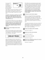
QUESTIONS?
As a manufacturer, we are cornrnitted to providing complete
customer satisfaction. If you
have questions, or if parts are
damaged or missing, PLEASE
CONTACT OUR CUSTOMER
SERVICE DEPARTMENT
DIRECTLY.
CALL TOLL-FREE:
1-888-533-1333
Moao-Fri., 6 a.rn.-6 p.m. MST
Sat. 8 a.rn.-5 p.m. MST
ON THE WEB:
www.proforrnservice.corn
Read all precautions and instructions in this manual before using
this equipment. Keep this rnanuo
aJ for future reference.
www, proform,oom
new products,
prizes,
fitness tips, and much more!
®
TABLE OF CONTENTS
IMPORTANT PRECAUTIONS
................................................................
BEFORE YOU BEGIN ......................................................................
ASSEMBLY ...............................................................................
HOW TO USE THE ELLIPTICAL EXERCISER ..................................................
MAINTENANCE AND TROUBLESHOOTING
...................................................
CONDITIONING GUIDELINES ...............................................................
PART LIST ..............................................................................
EXPLODED DRAWING ....................................................................
ORDERING REPLACEMENT PARTS ..................................................
LIMITED WARRANTY ..............................................................
PROFORM is a registered trademark of ICON IP, Inc,
2
3
4
5
12
21
22
24
26
Back Cover
Back Cover
m
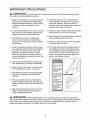
iMPORTANT PRECAUTmONS
WARNING: Toreduce
ther skofse.ousnjury,
read
thefo.owing
important precautionsbefore using the elliptical exerciser,
1. Read all instructions
in this manual and all
warnings on the elliptical exerciser before
using the elliptical exerciser. Use the eHi ptieal exercise onJy as described in this
manual,
10. The pulse sensor is
Various factors may
heart rate readings.
intended only as an
ing heart rate trends
2. it is the responsibility
of the owner to ensure
that aH users of the elliptical exerciser are
adequately informed of all precautions.
11. Keep your back straight whiJe using the eliiptical e×erciser; do not arch your back.
3=
The elliptical exerciser is intended for
home use only. Do not use the elliptical
exerciser in a commercial, rentaJ, or institutional setting,
4. Keep the elliptical exerciser indoors, away
from moisture and dust. Place the elliptical
exerciser on a tevel surface, with a mat
beneath it to protect the floor or carpet.
Make sure that there is enough clearance
around the elliptical exerciser to mount, dismount, and use it.
not a medical device.
affect the accuracy of
The pulse sensor is
exercise aid in determinin general
12. If you feel pain or dizziness while exercising,
stop immediately and cool down.
13. When you stop e×ercislng,
to slowly come to a stop.
allow the pedals
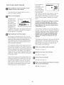
14. The decal shown below has been placed on
the eHi ptieal exerciser. If the decal is missing or illegible, call toll-free telephone number on the front cover of this manua! and
order a free repJaeement decal Apply the
decal in the location shown.
5. inspect and properly tighten all parts regularly. Beplace any worn parts immediately.
6. Keep children nnder age 12 and pets away
from the elliptical exerciser at all times.
7o The elliptical exerciser should not be used
by persons weighing more than 256 Ibs.
(124 kg).
8. Wear appropriate exercise eJothes while
using the eHipticaJ exerciser. Always wear
athletic shoes for foot protection while exercising.
9.
Hold the handgrip pulse sensor or the handlebars when mounting, dismounting,
or
using the elliptical exerciser.
A WARNING : Before
beginning
this or any exercise
program,
consult
your
physician.
This is especiaH_ important for persons over the age of 35 or persons with pre-existing health problems. Read aH instructions before using, iCON assumes no responsibility
for personaJ injury or
property
damage sustained
by or through the use of this product.
BEFORE YOU BEGIN
Thank you for selecting the revolutionary PROFORM _'
20.0 CROSSTRAINER elliptical exerciser. The 20.0
CROSSTRAINER elliptical exerciser provides a wide
array of features designed to make your workouts at
home more effective and enjoyable.
tacting us. The model number is PFEL7806.0. The
sedal number can be found on a decal attached to the
elliptical exerciser (see the front cover of this manual
for the location of the decal).
To avoid a registration fee for any service needed
under warranty, you must register the elliptical
exerciser at www.proformserviceocom/registration.
For your benefit, read this manual carefully before
you use the elliptical exerciser. If you have questions after reading this manual please see the front
cover of this manual To help us assist you, note the
product model number and serial number before con-
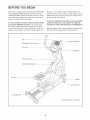
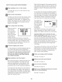
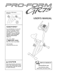
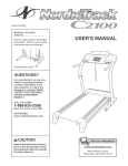
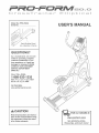
Before reading further, please familiarize yourself with
the parts that are labeled in the drawing below.
Fan
Game Controller
Handgdp Pulse Sensor
Console
Handlebar
Accessory Tray
Water Bottle Holder*
Pedal
Wheel
\
Leveling Foot
Leveling Foot
*No water bottle is included
4
To hire an authorized
service technician
to assembJe the elliptical
exerciser,
call toll-free
1-800-445-2480.
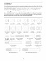
AssembJy requires two persons. PJace aJl parts of the eJJipticaJexerciser in a cleared area and remove the
packing matedaJs. Do not dispose of the packing materials until assembly is compJeted, Jn addition to the
incJuded he× keys, assembly requires a phHJips screwdriver
_;I
.......
, an adjustable
wrench
,andarubbermaHet
_-TI
_ -z_(_"
As you assembJe the eJliptical exerciser, use the drawings below to identify smaJl parts, The number in parentheses
beJow each drawing is the key number of the part, from the PART LIST on pages 20 and 21, The number foJJowing the parentheses is the quantity needed for assembly, Note: Some small parts may have been preassembJed. tf a part is not in the parts bag, check to see if it has been preassembted.
D
H
Star Washer
(100)-3
M4 x 13mm
Washer (93)-2
M6 Split
Washer (88)-8
M4 x 16mm
Self-tapping
Screw (79)-16
MIO x 20mm x
1,5mm Washer
(84)-2
M4 x 16mm
Screw (86)-8
M8 Split
Washer (72)-4
Wave Washer
(98)-8
_--_
<>/
MIO x 20mm x
1mm Washer
(81)-2
M8 x 15mm x 4,5mm
Washer (99)-4
/
MIO x 20mm x
2ram Washer
(92)-4
M6 x 35mm Phillips
Screw (87)-8
M8 x 75mm Button
Screw (107)-4
MIO x 62mm Bolt (89)-2
_x\/
MIO x 25ram
Washer (94)-4
L
M8 Nylon
Locknut (96)-4
M8 x 42mm Bolt
(71)-4
MIO x 20mm Button
Screw (91)-4
MIO Nylon
Locknut (97)-2
M8 x 16mm Button
Screw (95)-3
MIO x 23mm Shoulder
Screw (80)-8
MIO x 78mm Button Screw (90)-2
mationon
89
page 5 before YQUbegin assem_
25
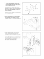
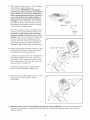
Orient the the Front Stabilizer (35) as shown,
Attach the two Wheels (25) to the Front Stabilizer
with two M10 x 62mm Bolts (89) and two M10
Nylon Locknuts (97),
\
89_
35
Attach two Leveling Feet (26) to the underside of
the Front Stabilizer (35),
26
Have a second person tip the Frame (2) backward, Attach the Front Stabilizer (35) to the
Frame with two M10 x 78mm Button Screws (90),
2
9O
\
35
Position the Base (1) near the Frame (2) as
shown, See the inset drawing, Attach two
Leveling Feet (26) to the underside of the Base,
3
Have a second person tip the Frame (2) forward,
Insert the Base (1) into the Frame, Attach the
Base with four M8 x 75mm Button Screws (107),
four M8 Split Washers (72), and four
M8 x 15mm x 4,5mm Washers (99),
107
6
107
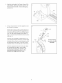
4. Hook the front ends of the Frame Covers (105,
106) together. Attach each Frame Cover to the
Frame (2) with three M4 x 16mm Self-tapping
Screws (79).
4
106
79
105
Have a second person hoJd the Upright (6) near
the Frame (2) as shown.
Puff the Wire Harness (48) out of the Frame (2)
and insert it upward through the Upright (6). Do
not let the Wire Harness or the ControJJer Wires
(110, 111) falJ into the Upright; use a piece of
tape or an eJastic band to hoJd the wires in place
untiJ step 15.
111
11
Insert the Left and Right ControJJer Wires (110,
111) downward into the Frame (2). Puff the Right
Controller Wire, which has a tag attached, out of
the right side of the Frame. Then, pulJ the Left
ControJJer Wire out of the left side of the Frame.
IO0
'\
Insert the Upright (6) into the Frame (2). Attach
the Upright with three M8 x 16mm Button
Screws (95) and three Star Washers (100).
Avoid pinching the Wires (48, 110, 111)
between the Upright and the Frame.
7
Avoid pinching
the wires during
this step.
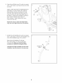
6. Orient the Left Roller Leg (12), which is marked
with a "Left" sticker, near the left Crank Arm (36)
as shown.
6
98
Apply a small amount of the included grease to
both sides of a Wave Washer (98). Slide the
Wave Washer onto the end of the left Crank
Arm (36). Next, slide the Left Roller Leg (12)
onto the Crank Arm and set the Roller (22) on
the Base (1). Attach the Left Roller Leg with an
M10 x 23ram Shoulder Screw (80), an
M10 x 20mm x 1.5mm Washer (84), and a
Crank Axle Cap (30).
30
84
21
8O
Repeat this step to attach the Right Roller
Leg (21) to the right Crank Arm (not shown}.
22
Identify the Left Handlebar (8), which is marked
with a "Left" sticker. Insert the Left Handlebar into
one of the Handlebar Legs (11) as shown.
i
Attach the Left Handlebar (8) with two
M8 x 42mm Bolts (71) and two M8 Nylon
Locknuts (96). Make sure that the Nylon
Locknuts are inside the hexagonal holes.
Assemble the Right Handlebar and the other
Handlebar Leg (not shown} in the same way.
96
Hexagonal
71
11
,i
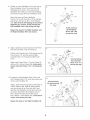
Cover(18)andan
8. Positionan InnerHandlebar
OuterHandlebar
Cover(19)aroundtheLeft
Handlebar
(8)asshown.Then,pulltheLeft
Handlebar
Wire(108)outoftheLeftHandlebar
andinsertit throughthe InnerHandlebar
Cover.
8
AttachtheInnerandOuterHandlebar
Covers(18,19)withthreeM4x 16mmSelfotapo
pingScrews(79)andanM4x 13mmWasher
(93).Startall threeSelf-tappingScrewsbefore
tighteninganyof them.Avoidpinchingthe
Left Handlebar Wire (108) during this step.
Avoid pinching
the Handlebar
Wires (108, 109)
during this step.
/
/
I
Repeat this step for the Right Handlebar
the Right Handlebar Wire (not shown).
/
/
/
and
/'
/ /
/ i
Apply a generous amount of grease to the Pivot
Axle (65) and insert it into the Frame (2).
111
Pull the Left Controller Wire (110) through the left
Frame Cover (17), and then pull the Right
Controller Wire (111) through the right Frame
Cover.
Avoid pinching
the Controller
Wires (110, 111)
during this step
Attach each Frame Cover (17) to the Frame (2)
with two M4 x 16mm Screws (86). Avoid pinching the Controller Wires (110, 111) during this
step.
10. Connect the Left Handlebar Wire (108) to the
Left Controller Wire (110). Insert the excess wire
into the Left Handlebar (8).
10
Avoid pinching
the wires during
this step.
Apply a small amount of grease to both sides of
a Wave Washer (98). Slide the Wave Washer
onto the left side of the Pivot Axle (65). Next,
slide the Left Handlebar (8) onto the Pivot Axle
as shown. Attach the Left Handlebar with an
M10 x 23mm Shoulder Screw (80) and an
M10 x 20mm x lmm Washer (81). Avoid pinching the wires during this step.
Repeat this step for the Right Handlebar
81
8O..
Grease
(9).
9
110
11. Identify the Left Pedal (13) and the Left Pedal
Leg (14), which are marked with "Left" stickers,
and orient them as shown.
11
Attach the Left Pedal (13) to the Left Pedal
Leg (14) with four M6 x 35mm Phillips
Screws (87) and four M6 Split Washers (88).
Start aJJfour Phillips Screws before tightening any of them.
14
Repeat this step to attach the Right Pedal to
the Right Pedal Leg (not shown).
88d
'%87
12. Apply a generous amount of grease to two Pedal
Leg Axles (32). Insert one Pedal Leg Axle into
the bottom of the Left Handlebar Leg (11). Insert
the other Pedal Leg Axle into the Left Roller
Leg (12).
12
11
Apply a small amount of grease to both sides of
two Wave Washers (98). Place a Wave Washer
on each Pedal Leg Axle (32).
Grease
32
Orient the Left Pedal Leg (14) as shown, and
slide it onto the Pedal Leg Axles (32). Attach the
Left Pedal Leg to the Left Handlebar Leg (11)
with two M10 x 23mm Shoulder Screws (80), two
M10 x 20mm x 2mm Washers (92), and two Axle
Caps (31).
94
98.
92
Attach the Left Pedal Leg (14) to the Left Roller
Leg (12) with two M10 x 20mm Button
Screws (91) and two M10 x 25ram Washers (94);
do not overtighten the Button Screws. The
Legs (11, 14, 12) must pivot freeJy.
31
8O
Repeat this step for the Right Pedal Leg (not
shown).
14
91
10
13. The Console (5) requires four 1.5V "D" batteries
(not included); alkaJine batteries are
recommended. IMPORTANT: If the eHipical
exerciser has been exposed to cold temperatures, allow it to warm to room temperature
before inserting batteries into the Consoleo If
you do not do this, the console disptays or
other eJectronic components
may become
damaged. Remove the battery cover and insert
four batteries into the Console. Make sure that
13
/
the batteries are oriented as shown at the right.
Then, reattach the battery cover.
5
Batteries
Note: The Console (5) can be operated with an
optional power supply instead of batteries. To
purchase a power suppJy, call the toil-free
teJephone number on the front cover of this
manual Plug one end of the power supply into
the jack at the front of the elliptical exerciser.
Plug the other end of the power supply into an
appropriate outlet that is properly installed in
accordance with all local codes and ordinances.
\
Battery
Cover
14
Console Wire Harness
14. Have a second person hold the Console (5) near
the Upright (6) as shown. Connect the console
wire harness to the Wire Harness (48).
79 48
"-Left Wire
Connect the right wire, which has a tag attached,
to the Right Controller Wire (111), which has a
tag attached. Then, connect the left wire to the
Left Controller Wire (110). insert the excess wire
downward into the Upright (6).
ght Wire
Attach the Console (5) to the Upright (6) with
four M4 x 16mm Self-tapping Screws (79).
15. Attach the Left and Right Upright Covers (10, 64)
to the Upright (6) with four M4 x 16mm
Screws (86).
15
10
86
16. Make sure that aH parts of the elliptical exerciser are properly tightened. Note: Some hardware may be
left over after assembly is completed. To protect the floor or carpet from damage, place a mat under the
elliptical exerciser.
11
HOW TO USE THE ELLIPTICAL
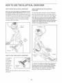
HOW TO MOVE THE ELUPTICAL
EXERCISER
HOW TO EXERCISE ON THE ELUPTtCAL
EXERCISER
Due to the size and weight of the eltipticaJ exerciser, moving it requires two persons. Stand in front of
the elJipticaJ exerciser, hoJd the upright, and pJace one
foot against one of the front wheels. Pull on the upright
and have a second person lift the base until the elliptical exerciser will roll on the front wheels. Carefully
move the elliptical exerciser to the desired location,
and then lower it to the floor.
To mount the eJliptical exerciser, hold the handlebars
and step onto the pedal that is in the lower position.
Then, step onto the other pedal. Push the pedals untiJ
they begin to move with a continuous motion. Note:
The crank arm covers can turn in either direction.
tt is recommended that you turn the crank arm
covers in the direction shown by the arrow below;
however, for variety, you can turn the crank arm
covers in the opposite direction.
Pull on
• ht
J
EXERCISER
Handlebars
Place
your foot
here
Lift here
Pedals
HOW TO LEVEL THE ELLIPTICAL
exerciser
rocks slightly
on your floor
during use,
turn one or
If the of
elliptical
both
the leveJing feet
beneath the
base or
EXERCISER
o _c
I
To dismount the elliptical exerciser, wait until the pedals come to a complete stop. Note: The elliptical
exerciser does not have a free wheel; the pedals
will continue to move untiJ the flywheel stops.
When the pedals are stationary, step off the higher
pedal first. Then, step off the lower pedal
Levelin
Feet
beneath the front stabilizer untiJ the rocking motion is
eliminated.
12
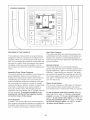
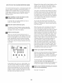
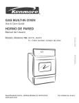
CONSOLE DtAGRAM
iNTERACTIVE
CROSS
TRAINER
PROGRAMS
V
CERTHED
PERSONAL
TRAINER
PROGRAMS
ENTER
1
12
II
2
11
II
3
lO
II
4
9
JJ
J
FEATURES OF THE CONSOLE
Heart Rate Programs
The console also offers two heart rate programs that
automatically control the resistance of the pedals and
prompt you to maintain a constant pedaling pace to
keep your heart rate near target heart rate settings during your workouts,
The revolutionary console offers an array of features
designed to make your workouts more effective and
enjoyable, When you use the manual mode of the console, you can change the resistance of the pedals with
the touch of a button, While you exercise, the console
will display continuous exercise feedback, You can
also measure your heart rate using the handgrip pulse
sensor,
Interactive Cross Trainer Programs
The console features nine interactive cross trainer pro=
grams designed to help you to burn calories and
develop your cardiovascular system while toning and
strengthening your muscles, The cross trainer programs automatically control the resistance of the pedals and prompt you to perform a variety of strength
exercises during your workout, Choose an upper body,
lower body, or total body cross trainer program to
focus your workout, Note: The strength exercises
require the use of dumbbells and an inflatable exercise
ball (not included), To purchase dumbbells or an
exercise ball, call the toll-free telephone number
on the front cover of this manual.
Smart Programs
In addition, the console offers three smart programs,
Each program automatically changes the resistance of
the pedals and prompts you to vary your pedaling
pace as it guides you through an effective workout,
Interactive Games
The console features two motivational interactive
games, Using the dual game controllers, play the challenging Fat Blocker TM game or the fast-paced Calorie
Destroyer TM game during your workouts--the harder
you exercise, the greater the advantage you will have!
The console keeps track of the four highest scores for
each game--compete with other users or try to top
your own high score,
Stereo Sound System
You can even connect your MP3 player or CD player
to the console's stereo sound system and listen to
your favorite music or audio books while you exercise,
To use the manual mode of the consoJe, follow the
steps beginning on page 14, To use a cross trainer
program, see page 15, To use a smart program, see
page 17, To use a heart rate program, see page 18,
To play the Fat Blocker game, see page 19, To pJay
the Calorie Destroyer game, see page 20, To use
the stereo sound system, see page 21,
13
HOW TO USE TNEMANUAL
Follow your progress
MODE
with the dispJay.
The upper left corner of the display will show
the elapsed time. Note: When a program is selected, the display will show the time remaining in the
program instead of the elapsed time.
Note: If there is a sheet of clear plastic on the face
of the console, remove the plastic.
Begin pedaling or press any button on the
console to turn on the console.
A moment after you begin pedaling or press a
button, the display will light.
Select the manual
mode.
Each time you
turn on the console, the manual
mode will be
selected. If you
have selected a
program, reselect
the manual mode by pressing either of the
Programs buttons repeatedly until the words MANUAL MODE appear in the lower left corner of the
display.
Change the resistance
desired.
DISTANCE
RPM
The Jower left corner of the display will show
the distance, in total revolutions, you have pedaled.
of the pedals as
The upper right corner of the display will show
the approximate number of calories you have
burned. The upper right corner of the display will
also show your heart rate when you use the handgrip pulse sensor (see step 5 on page 15).
As you pedal,
change the resistance of the pedals by pressing
any of the Quick
Resistance
buttons numbered 1 through 12. Note: After you press the
buttons, it will take a moment for the pedals to
reach the selected resistance level.
The Jower right corner of the dispJay will show
your pedaling pace in revolutions per
minute (rpm).
The center of the dispJay will show the resistance setting of the pedals for a few seconds each
time the resistance setting changes.
You can also view selected information at a larger
size. Press the Display button repeatedly to view
time and distance information, time and calorie
information, or time and pace information. Press
the Display button again to view all information. To
reset the display information, press the
Start/Reset button.
The console has three backlight options. The "On"
option keeps the backlight on while the console is
on. To conserve the batteries, the "Auto" option
keeps the backlight on only while you are pedaling. The "Off" option turns the backlight off. To
select a backlight option, first press and hold
down the Certified Personal Trainer Programs button for several seconds. Next, press the increase
button to select the desired backlight option.
Then, press the Certified Personal Trainer
Programs button to save your selection.
14
Measure your heart rate if desired.
HOW TO USE A CROSS TRAINER PROGRAM
tf there are
sheets of dear
plastic on the
metaJ contacts
on the handgdp
puJse sensor,
remove the plastic. To measure
Begin pedaling or press any button on the
console to turn on the consote.
Contacts
A moment after you begin pedaling or press a
button, the dispJay wiJJlight.
SeJect a cross
your heart rate,
hold the handgrip
pulse sensor with
your palms resting against the metal contacts.
Avoid moving your hands or gripping the contacts too tightly.
program.
To select one of
ProfiJe
the nine cross
trainer programs,
press the
Interactive Cross
Trainer Programs
button repeatedly
untiJ Program 1, 2,
3, 4, 5, 6, 7, 8, or 9 appears in the display. The
program time and a profiJe of the resistance settings for the program will also appear in the display.
When your puJse is detected, one, two, or three
dashes will appear in the display, and then your
heart rate wilJ appear. For the most accurate heart
rate reading, hold the contacts for at least 15 seconds. Note: if you continue to hold the handgdp
pulse sensor, the display wiiJ show your heart rate
for up to 30 seconds.
After a moment, the voice of a personal trainer
will welcome you to the program and guide you
through the workout. To adjust the volume level of
the speakers, press the increase and decrease
buttons untiJ the desired voJume level is selected.
There are five volume leveJs.
If the dispJay does not show your heart rate, make
sure that your hands are positioned as described.
Be careful not to move your hands excessively or
to squeeze the metal contacts too tightly. For optimaJ performance, clean the metal contacts using
a soft cJoth; never use alcohol, abrasives, or
chemicals to dean the contacts.
Begin pedaling
Turn on the fan if desired.
to start the program.
Each program is divided into either 30 or 45 oneminute segments. One resistance setting and one
target rpm (pace) setting are programmed for
most segments. (Note: The same resistance
and!or target rpm setting may be programmed for
two or more consecutive segments.) During other
segments, the console will prompt you to perform
strength exercises.
To turn on the fan at low speed, press the Fan
button once. To turn on the fan at high speed,
press the Fan button a second time. To turn off
the fan, press the Fan button a third time.
When you are finished exercising,
wilJ turn off automaticaHyo
trainer
the console
The resistance setting and the target rpm for the
first segment will appear in the center of the display for a few seconds. The resistance setting will
then be indicated by the height of the flashing column of the profile in the display. The resistance
settings for the next several segments will be indicated by the heights of the columns to the right of
the flashing coJumn.
If the pedaJs do not move for several seconds, a
tone wilJ sound and the console will pause. If the
pedals do not move for several minutes and the
buttons are not pressed, the console wiJJturn off
and the display will be reset.
When the first segment of the program ends, the
resistance setting and the target rpm for the second segment will appear in the center of the display for a few seconds to alert you. The entire
profiJe wiJJthen shift one column to the Jeff, and
the pedals will automaticaJJy adjust to the resistance setting for the second segment.
15
As you exercise,
you will be
prompted to keep
your pedaling
pace near the target rpm setting for
the current segment. When an upward arrow appears in the display, increase your pace. When a downward
arrow appears in the display, decrease your pace.
When no arrows appear, maintain your current
pace.
Note: Refer to the accompanying exercise chart
to see the correct form for each exercise. When
performing lunges, alternate legs with each repetition. When performing dumbbell rows, perform
half the repetitions with your right arm and half
the repetitions with your left arm. The strength
exercises require the use of dumbbells and an
inflatable exercise ball (not included). To purchase dumbbells or an exercise baH, call the
toll=free telephone number on the front cover
of this manual
Continue the cross trainer
Important: The target rpm settings are intended only to provide motivation. Your actual
pace may be slower than the target rpm settings. Make sure to exercise at a pace that is
comfortable for you.
When you have performed the recommended
number of repetitions, the words START STRIDING will appear in the display. To continue the
cross trainer program, step onto the exerciser and
start pedaling. The pedals will automatically
adjust to the resistance setting for the next segment.
If the resistance setting for the current segment is
too high or too low, you can manually override the
setting by pressing the Quick Resistance buttons.
Important: When the current segment of the
program ends, the pedals will automatically
adjust to the resistance setting for the next
segment.
Perform the first strength
prompted.
exercise
program.
The program will continue in this way until the last
segment ends. To stop the program at any time,
stop pedaling. A tone will sound and the time will
begin to flash in the display. To restart the program, simply resume pedaling.
when
Follow your progress
with the display.
See step 4 on page 14.
When the first strength exercise segment begins,
the name of the first strength exercise will appear
in the display for a few seconds. The time will
pause and flash in the display.
Measure your heart rate if desired.
See step 5 on page 15.
Turn on the fan if desired.
See step 6 on page 15.
Step off the elliptical exerciser and prepare to
begin the first strength exercise. Perform repetitions of the exercise as directed by the personal
trainer. Exercise with a slow, steady motion; do
not perform more than one repetition during each
interval indicated by the personal trainer. The display will also count the repetitions as you perform
them.
When you are finished exercising,
will turn off automatically.
See step 7 on page 15.
16
the console
As you exercise,
you will be
prompted to keep
your pedaling
pace near the target rpm setting for
the current segment. When an upward arrow appears in the display, increase your pace. When a downward
arrow appears in the display, decrease your pace.
When no arrows appear, maintain your current
pace.
HOW TO USE A SMART _ROGRAM
Begin pedaling or press any button on the
console to turn on the console.
A moment after you begin pedaling or press a
button, the display will light.
Select a smart program.
To select one of
the three smart
Profile
programs, press
the Certified
Personal Trainer
Programs button
repeatedly until
Program 1,2, or
3 appears in the display. The program time and a
profile of the resistance settings for the program
will also appear in the display.
Important: The target rpm settings are intended only to provide motivation. Your actuaJ
pace may be slower than the target rpm settings. Make sure to exercise at a pace that is
comfortable for you.
If the resistance setting for the current segment is
too high or too low, you can manually override the
setting by pressing the Quick Resistance buttons.
Important: When the current segment of the
program ends, the pedals will automatically
adjust to the resistance setting for the next
segment.
Begin pedaling to start the program.
Each program is divided into 20, 30, or 45 oneminute segments. One resistance setting and one
target rpm (pace) setting are programmed for
each segment. Note: The same resistance and/or
target rpm setting may be programmed for two or
more consecutive segments.
The program will continue in this way until the last
segment ends. To stop the program at any time,
stop pedaling. A tone will sound and the time will
begin to flash in the display. To restart the program, simply resume pedaling.
The resistance setting and the target rpm for the
first segment will appear in the center of the display for a few seconds. The resistance setting will
then be indicated by the height of the flashing column of the profile in the display. The resistance
settings for the next several segments will be indicated by the heights of the columns to the right of
the flashing column.
Follow your progress
with the disptay.
See step 4 on page 14.
Measure your heart rate if desired.
See step 5 on page 15.
When the first segment of the program ends, the
resistance setting and the target rpm for the second segment will appear in the center of the display for a few seconds to alert you. The entire
profile will then shift one column to the left, and
the pedals will automatically adjust to the resistance setting for the second segment.
Turn on the fan if desired.
See step 6 on page 15.
When you are finished exercising,
will turn off automaticaHyo
See step 7 on page 15.
17
the consote
,oWTOUSE
A.EART
RATE
F'ROGRAM
When the first segment of the program ends, the
entire profile will shift one column to the left. The
target heart rate setting for the second segment
will then be shown in the flashing column of the
profile.
Begin pedaling to turn on the console.
A moment after you turn on the console, the display will light,
As you pedal, the console will regularly compare
your heart rate to the target heart rate setting. If
your heart rate is too far below or above the target
heart rate setting, the resistance of the pedals will
automatically increase or decrease to bring your
heart rate closer to the target heart rate setting.
Select a heart rate program.
To select one of the two heart rate program, press
the Certified Personal Trainer Programs button
repeatedly until Heart Rate 1 or 2 appears in the
display. The program time and a profile of the target heart rate settings for the program will also
appear in the display.
You will also be
prompted to pedal
at a steady pace.
When an upward
arrow appears in
the display,
increase your
pace. When a downward arrow appears in the
display, decrease your pace. When no arrows
appear in the display, maintain your current pace.
Enter a target heart rate setting.
When you select a
heart rate program, the maximum target heart
R_JJHST
}{EH_T
MR_
_H'_E
rate setting will
flash in the center
of the display, if
desired, use the
increase and decrease buttons to change the
maximum target heart rate setting, and then press
the Enter button. Note: If you change the maximum target heart rate setting, the intensity level
of the entire program will change.
Important: Make sure to exercise at a pace
that is comfortable for you. Note: You can manually override the resistance settings; however,
you may not maintain the target heart rate. Also,
when the console compares your heart rate to the
target heart rate setting, the resistance of the
pedals may automatically increase or decrease to
bring your heart rate closer to the target heart
rate setting.
Hotd the handgrip pulse sensor.
The program will continue in this way until the last
segment ends. To stop the program at any time,
stop pedaling. A tone will sound and the time will
begin to flash in the display. To restart the program, simply resume pedaling.
It is not necessary to hold the handgdp pulse sensor continuously during a heart rate program;
however, you should hold the handgrip pulse sensor frequently for the program to operate properly.
Each time you hold the handgdp pulse sensor, keep your hands on the metal contacts
for at least 30 seconds.
Follow your progress
with the display.
See step 4 on page 14.
Begin pedaling to start the program.
Measure your heart rate if desired.
Each heart rate program is divided into either 20 or
30 one-minute segments. One target heart rate
setting is programmed for each segment. Note:
The same target heart rate setting may be programmed for two or more consecutive segments.
See step 5 on page 15.
Turn on the fan if desired.
See step 6 on page 15.
The target heart rate setting for the first segment
will be indicated by the height of the flashing column of the profile in the display. The target heart
rate settings for the next several segments will be
indicated by the heights of the columns to the
right of the flashing column.
When you are finished exercising,
will turn off automatically.
See step 7 on page 15.
18
the consote
Your goal is to
maneuver the
blocks so that they
form a complete
row of black
squares across
the entire arena.
HOW TO PLAY THE FAT BLOCKER GAME
The Fat Blocker game requires quick thinking and fast
reflexes. In addition to the console buttons, you will
use the four-button game controllers on the handlebar
to play the game. Follow the steps below to play the
Fat Blocker game.
J
As you play, the blocks will fall faster and faster;
however, your pedaling pace will affect the speed
of the blocks--the faster you pedal, the more
slowly the blocks will fall, giving you extra time to
position and orient the blocks. The game will continue until any part of a stacked block reaches the
top of the arena.
A moment after you begin pedaling or press a
button, the display will light.
Select the Fat Blocker game.
To select the Fat Blocker game, press the Fat
Blocker button. The words FAT BLOCKER will
appear at the top of the display.
When the game ends, the display will show your
final score and the level of play that you reached.
The display will then show the four highest scores
recorded since the scores were reset. If desired,
press and hold down the right button on either
controller to reset the scores. Note: If your score
is one of the four highest, the display will prompt
you to enter a name consisting of three letters or
digits. While the line below the first letter is flashing, press the up and down buttons on either controller to select the desired letter or digit. Next,
press the right button on either controller and
select another letter or digit. Repeat this process
to select a third letter or digit. Then, press the
right button on either controller again. The display
will then show the four highest scores recorded
since the scores were reset.
Pedal to start the game,
When you start the Fat Blocker game, a game
arena will appear in the center of the display.
F
GAME 1
°1
Each time you complete a row of black squares,
the row will disappear, and all blocks above will
move downward one row.
Begin pedaling or press any button on the
eonsoJe to turn on the console.
TaME
_'_
CALORIES
RPM
Follow your progress
with the dispJay.
While you exercise and play the Fat Blocker
game, the corners of the display will show the
elapsed time, the approximate number of calories
you have burned, and your pedaling pace. In addition, the display will show your current score and
the game level that you have reached.
A block composed of four or five black squares
will slowly move downward until it reaches the
bottom of the arena. Another block will then move
downward. There are blocks of eight different
shapes. As each block falls, you can move it to
the left or right using the left and right buttons on
the left controller. In addition, you can rotate the
block counterclockwise or clockwise using the left
and right buttons on the right controller. Once you
have positioned and oriented a block, you can
speed its motion to the bottom of the arena, if
desired, by pressing the down button on either
controller.
To pause the game, press the Display button. To
resume the game, press the Display button
repeatedly until the words FAT BLOCKER appear
at the top of the display, and then begin pedaling.
When you are finished exercising,
wHI turn off automatically.
See step 7 on page 15.
19
the consote
Between the drones and the laser blaster are five
shields. You can hide the laser blaster below a
shield if desired. However, each time a shield is
hit by a laser, a piece will be vaporized.
HOW TO PLAY THE CALORIE DESTROYER GAME
The Calorie Destroyer game is a fast-paced game that
pits you against a squadron of Jaser-fidng drones. In
addition to the consoJe buttons, you will use the fourbutton game controllers on the handlebar to play the
game. Follow the steps below to play the Calorie
Destroyer game.
Your goal is to keep the laser blaster from being
hit and to keep any drone from reaching the bot=
tom of the arena. If the laser Master is hit, it wiJ}
be disabled and another laser blaster will appear
in its place; there are a total of four laser blasters.
If you vaporize the entire squadron of drones, a
new squadron will appear.
Begin pedaJing or press any button on the
console to turn on the consoJe.
As you play, the drones wiiJ move faster and
faster. The game will continue until all four laser
blasters are disabled or a drone reaches the bottom of the arena.
A moment after you begin pedaling or press a
button, the dispJay writ light.
SeJect the Calorie
Destroyer
game.
To select the Calorie Destroyer game, press the
Calorie Destoyer button. The word DESTROYER
will appear at the top of the display.
When the game ends, the display will show the
leveJ of play that you reached and your final
score. The display will then show the four highest
scores recorded since the scores were reset. If
PedaJ to start the game.
desired, press and hold down the right button on
either controller to reset the scores. Note: If your
score is one of the four highest, the display will
prompt you to enter a name consisting of three
letters or digits. While the line below the first letter
is flashing, press the up and down buttons on
either controller to select the desired letter or
When you start the Calorie Destroyer game, a
game arena will appear in the display. Three rows
of drones will begin to move across the top of the
arena, periodically firing their lasers downward.
Each time the drones reach the left or right side
of the arena, they wilJ reverse direction and move
downward.
TIME
GAME
digit. Next, press the right button on either controller and select another letter or digit. Repeat
this process to select a third Jetter or digit. Then,
press the right button on either controlJer again.
The display will then show the four highest scores
recorded since the scores were reset.
2
Lt
VVVVVVVV
VV
VVVVV
VVVVV
Follow your progress
with the dispJay.
While you exercise and play the Calorie Destroyer
game, the upper left corner of the display wilJ
show the elapsed time. In addition, the display will
show the game level that you have reached and
your current score.
To pause the game, press the Display button. To
resume the game, press the Display button
repeatedly until the word DESTROYER appears at
the top of the display, and then begin pedaJing.
At the bottom of the arena is a laser blaster. You
can fire the laser blaster at the drones by pressing the up button on either controller. In addition,
while you are pedaJing, you can move the laser
blaster to the left or right using the left and right
buttons on either controJler. The faster you pedaJ,
the faster the laser blaster will move.
When you are finished exercising,
will turn off automaticaHyo
See step 7 on page 15.
2O
the consote
Next, press the play button on your MP3 player or CD
player. Adjust the volume of the speakers using the
volume control on your MP3 pJayer or CD player.
HOW TOUSE THE STEREO SOUND SYSTEM
To play your own music or audio books through the
console's stereo sound system while you exercise,
first locate the jack under the ledge on the console.
Plug an audio cable (not included) into the jack on the
console and into a jack on your MP3 player or CD
player; make sure that the audio cabte is fulJy
ptugged in.
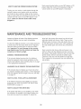
MAINTENANCE
AND TROUBLESHOOTING
Inspect and tighten all parts of the elliptical exerciser
reguiarJy. Replace any worn parts immediately.
drive beJt, first remove the screws from the Jeff and
right side shields (not shown). Note: There are two
different sizes of screws in the side shields. Be sure
to note the Jocafion of each screw. Then, gently pull
the side shields apart and remove the convenience
tray.
To clean the elliptical exerciser, use a damp cloth and
a small amount of mild soap. Make sure to regularly
clean the rollers and the track on which the rollers
ride. Important: To avoid damage to the console,
keep liquids away from the console and keep the
consoJe out of direct sunlight.
Next, locate the Idler Screw (68) and loosen it one
half turn. Step onto the elliptical exerciser and move
the pedaJs. If the pedaJs continue to slip, turn the Idler
Screw another half turn and test the pedals again.
Continue in this way untiJ the pedals no Jonger slip.
Then, repJace the convenience tray and reattach the
side shields.
CONSOLETROUBLESHOOTJNG
If the console display becomes dim, the batteries
should be replaced; most console problems are the
result of low batteries. See assembly step 13 on page
11 for replacement instructions.
HANDGRIP
PULSE SENSOR TROUBLESHOOTING
If the console does not display your heart rate when
you hold the handgnp pulse sensor, or if the displayed
heart rate appears to be too high or too low, see step
5 on page 15.
HOW TO LEVEL THE ELMPTICAL
EXERCISER
If the elliptical exerciser rocks slightly on your floor
during use, see HOW TO LEVEL THE ELLIPTICAL
EXERCISER on page 12.
HOW TO ADJUST THE DRIVE BELT
If the pedals slip while you are pedaJing, even whiJe
the resistance is adjusted to the highest setting, the
drive belt may need to be adjusted. To adjust the
21
CONDITIONING
GUIDELINES
desired results is to exercise with the proper intensity.
The proper intensity level can be found by using your
heart rate as a guide.
AWARNING'.
Before beginning this or any exercise program. consult your physician.This isespecially important for persons over the age of 35
or persons with pre-existing health problems.
The putse sensor is
Various factors may
heart rate readings,
intended only as an
ing heart rate trends
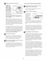
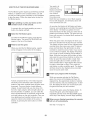
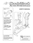
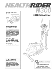
The chart below shows recommended heart rates for
fat burning, maximum fat burning, and cardiovascular
(aerobic) exercise.
not a medicaJ device.
affect the accuracy of
The pulse sensor is
exercise aid in determin_
in general,
The following guidelines will help you to plan your
exercise program, Remember that proper nutrition
and adequate rest are essential for successful results,
Each workout should include the following three parts:
_
145 138 130 125 118 110 !03
_)
125 120 115 II0 105 95
90
20
80
30
40
50
60
70
To find the proper heart rate for you, first find your age
at the bottom of the chart (ages are rounded off to the
nearest ten years). Next, find the three numbers
above your age. The three numbers are your "training
zone." The lowest number is the recommended heart
rate for fat burning, the middle number is the recommended heart rate for maximum fat burning, and the
highest number is the recommended heart rate for
aerobic exercise.
Warming Up--Begin each workout with 5 to 10 rain=
utes of stretching and light exercise, A proper warmup increases your body temperature, heart rate, and
circulation in preparation for exercise.
Training Zone Exercise--Each
workout should consist of 20 to 30 minutes of exercising with your heart
rate in your training zone. Note: During the first few
weeks of your exercise program, do not keep your
heart rate in your training zone for longer than 20 minutes.
Fat Burning--To
burn fat effectively, you must exercise at a relatively low intensity level for a sustained
period of time. During the first few minutes of exercise, your body uses easily accessible carbohydrate
calories for energy. Only after the first few minutes of
exercise does your body begin to use stored fat calories for energy. If your goal is to burn fat, adjust the
intensity of your exercise until your heart rate is near
the lowest number in your training zone as you exercise. For maximum fat burning, adjust the intensity of
your exercise until your heart rate is near the middle
number in your training zone as you exercise.
Cooling Down--End each workout with 5 to 10 min=
utes of stretching. This will increase the flexibility of
your muscles and will help to prevent post=exercise
problems.
To maintain or improve your condition, plan three
workouts each week, with at least one day of rest
between workouts. Schedule your workouts for the
time of day when your energy level is the highest.
After a few months of regular exercise, you may com=
plete up to five workouts each week, if desired.
Remember, the key to success is make exercise a
regular and enjoyable part of your everyday life.
CARDIOVASCULAR
Z65 155 145 140 130 125 115
Aerobic Exercise--If your goal is to strengthen your
cardiovascular system, your exercise must be "aerobic." Aerobic exercise is activity that requires large
amounts of oxygen for prolonged periods of time. This
increases the demand on the heart to pump blood to
the muscles, and on the lungs to oxygenate the
blood. For aerobic exercise, adjust the intensity of
your exercise until your heart rate is near the highest
number in your training zone.
TRAINING GUIDEUNES
Whether your goal is to burn fat or to strengthen your
cardiovascular system, the key to achieving the
22
STRENGTH TRAINING GUIDELINES
To increase the size and strength of your muscles,
you must work your muscles at a level close to their
maximum capacity, Your muscles will adapt and grow
as you progressively increase the amount of weight
that you use, You can tone your muscles by working
them at a moderate percentage of their capacity, The
proper amount of weight to use for each strength exercise depends on you--you must gauge your limits and
select an appropriate amount of weight,
During strength exercises, you must maintain proper
form for the best results, Maintaining proper form
involves moving through the full range of motion for
each exercise and moving only the appropriate parts
of the body, Exercising in an uncontrolled manner will
reduce the benefits of strength exercises, On the
exercise chart accompanying this manual are photographs showing the correct form for several strength
exercises,
It is important to avoid overdoing it during the first few
months of your exercise program, Progress at your
own pace and be sensitive to your body's signals, If
you experience pain or dizziness at any time while
exercising, stop immediately and cool down, Find out
what is wrong before continuing, Remember that ade o
quate rest and a proper diet are important factors in
any exercise program,
Perform each repetition of each strength exercise
smoothly and without pausing, The exertion phase of
each repetition should last only about half as long as
the return phase, Proper breathing is also important,
Exhale during the exertion phase of each repetition
and inhale during the return phase--never hold your
breath,
23
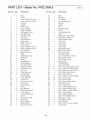
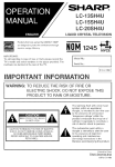
PART LlST Model
Key No. Qty.
1
2
3
4
5
6
7
8
9
10
11
12
13
14
15
16
17
18
19
20
21
22
23
24
25
26
27
28
29
30
31
32
33
34
35
36
37
38
39
40
41
42
43
44
45
46
47
48
49
50
1
1
2
2
1
1
2
1
1
1
2
1
1
1
1
1
2
2
2
2
1
2
2
2
2
4
4
1
1
2
4
4
8
4
1
2
1
2
1
1
12
2
1
2
1
8
4
1
2
1
No. PFEL7806.0
Description
Ro4o7A
Key No. Qty.
51
52
53
54
55
56
57
58
59
6O
61
62
63
64
65
66
67
68
69
70
71
72
73
74
75
76
77
78
79
80
81
82
83
84
85
86
87
88
89
90
91
92
93
94
95
96
97
98
99
100
Base
Frame
Outer Crank Arm Cover
Inner Crank Arm Cover
Console
Upright
Roller Cover
Left Handlebar
Right Handlebar
Left Upright Cover
Handlebar Leg
Left Roller Leg
Left Pedal
Left Pedal Leg
Right Pedal
Right Pedal Leg
Frame Cover
Inner Handlebar Cover
Outer Handlebar Cover
Axle Bearing
Right Roller Leg
Roller
Stabilizer Endcap
Roller Axle
Wheel
Leveling Foot
Wheel Bearing
Left Side Shield
Right Side Shield
Crank Axle Cap
Axle Cap
Pedal Leg Axle
Axle Bushing
Roller Bushing
Front Stabilizer
Crank Arm
Convenience Tray
Crank Hub
Pulley Spacer
Pulley
Axle Bushing
Pedal Leg Endcap
Crank Sleeve
Crank Bearing Set
Crank
Round Inner Cap
Snap Ring
Wire Harness
Base Endcap
Reed Switch/Wire
24
1
1
1
2
1
1
1
1
1
2
1
1
1
1
1
2
1
1
1
4
4
4
4
8
2
2
2
2
37
8
2
4
4
2
10
10
8
8
2
2
4
4
2
4
3
6
2
8
4
3
Description
Belt
Flywheel
"C" Magnet
Outer Bearing Set
Magnet
Spring
Idler
Flywheel Pulley
Clamp
Inner Bearing Set
Motor
Resistance Cable Pulley
Resistance Cable Set
Right Upright Cover
Pivot Axle
Hub Cover
Stop Screw
Idler Screw
M8 Flange Screw
M8 x 35mm Screw
M8 x 42mm Bolt
M8 Split Washer
M4 x 12mm Flange Screw
M8 x 25mm Screw
3/8" Flange Screw
Control Grip
Pivot Bushing
Game Controller
M4 x 16mm Self=tapping Screw
M10 x 23mm Shoulder Screw
M10 x 20mm x lmm Washer
M8 x 16mm Patch Screw
M8 x 25mm Washer
M10 x 20mm x 1,5mm Washer
M4 x 12mm Screw
M4 x 16mm Screw
M6 x 35mm Phillips Screw
M6 Split Washer
M10 x 62mm Bolt
M10 x 78mm Button Screw
M10 x 20mm Button Screw
M10 x 20mm x 2mm Washer
M4 x 13mm Washer
M10 x 25mm Washer
M8 x 16mm Button Screw
M8 Nylon Locknut
M10 Nylon Locknut
Wave Washer
M8 x 15mm x 4,5mm Washer
Star Washer
Key No. Qty.
101
102
103
104
105
106
107
108
2
1
2
1
1
1
4
1
Description
Key No. Qty.
M4 x lOmm Screw
Rear Base Cover
Side Base Cover
Center Base Cover
Left Frame Cover
Right Frame Cover
M8 x 75mm Button Screw
Left Handlebar Wire
109
110
111
112
*
*
*
1
1
1
1
4
1
1
Description
Right Handlebar Wire
Left Controller Wire
Right Controller Wire
M4 x 12mm Bright Screw
Hex Key
Grease
User's Manual
Note: ..... indicates a non°illustrated part, Specifications are subject to change without notice, See the back cover
of this manual for information about ordering replacement parts,
25
X
101..,
79 _
23
66
64
86
89
r
0
101
109
86
65
/
/
74
38,
47,
44-
.-'" 100
i ¢8
75
l
Z
17
0
98
96
98 95
106
41
19
1
93
81
0
104
0
Z
0
m
57
to
74
b
\
36
74
103o
66
107
o
_q
X
lie
O
33
33
32
15
31
14
8O
32
80 92
l
Z
41
91
94
1
86
30
,,,,q
54
/
!
79
O
87
54
Q.,
Z
©
80
21
32
-'t98
m
41%._
94
79
98
91
41
lie
34
91
94
O@
98
b
83
34
27
34
27
22
o
o
.,,q
>
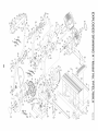
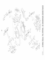
ORDERING
REPLACEMENT
PARTS
To order replacement parts, please see the front cover of this manual, To help us assist you, please be prepared
to provide the following information when contacting us:
• the MODEL NUMBER of the product (PFEL7806,0)
• the NAME of the product (PROFORM 20,0 CROSSTRAINER
elliptical exerciser)
• the SERIAL NUMBER of the product (see the front cover of this manual)
• the KEY NUMBER and DESCRIPTION
of the part(s) (see pages 24 to 27)
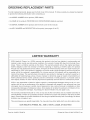
LIMITED WARRANTY
ICON Health & Fitness, Inc, (ICON) warrants this product to be free from defects in workmanship and
material, under normal use and service conditions, for a period of ninety (90) days from the date of purchase, There is a lifetime warranty on the frame, This warranty extends only to the original purchaser,
ICON's obligation under this warranty is limited to replacing or repairing, at ICON's option, the product
through one of its authorized service centers, All repairs for which warranty claims are made must be preauthorized by ICON, If the product is shipped to a service center, freight charges to and from the service
center will be the customer's responsibility, For in-home service, the customer will be responsible for a
minimal trip charge, This warranty does not extend to any product or damage to a product caused by or
attributable to freight damage, abuse, misuse, improper or abnormal usage or repairs not provided by an
ICON authorized service center; products used for commercial or rental purposes; or products used as
store display models, No other warranty beyond that specifically set forth above is authorized by ICON,
ICON is not responsible or liable for indirect, special or consequential damages arising out of or in connection with the use or performance of the product or damages with respect to any economic loss, loss
of property, loss of revenues or profits, loss of enjoyment or use, costs of removal or installation or other
consequential damages of whatsoever nature, Some states do not allow the exclusion or limitation of incidental or consequential damages, Accordingly, the above limitation may not apply to you,
The warranty extended hereunder is in lieu of any and all other warranties and any implied warranties of
merchantability or fitness for a particular purpose is limited in its scope and duration to the terms set forth
herein, Some states do not allow limitations on how long an implied warranty lasts, Accordingly, the above
limitation may not apply to you,
This warranty gives you specific legal rights, You may also have other rights which vary from state to state,
iCON HEALTH & FITNESS, iNC., 1500 So 1000 Wo, LOGAN, UT 84321=9813
Part No, 243571 R0407A
Printed in China _) 2007 ICON IP, Inc,