1
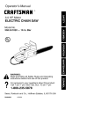
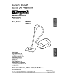
Operator's Manual
CRRFTSMRN
aft
GRINDER WITH STAND
Model No.
351.211930
CAUTION:
Read and follow
all Safety Rules and Operating
Instructions before First Use
of this Product.
Sears, Roebuck
www ,sears.corn/craftsman
2527300
Draft (03/09/07)
and Co., Hoffman
Estates,
IL 60179 U.S.A.
• Wear protective
hair covering
• Wear safety shoes
Warranty ....................................................
2
Safety
2
Rules ........................................
Unpacking
...............................................
4
Assembly
...................................................
4
Installation
..................................................
4-5
Operation
................................................
Maintenance
..........................................
Troubleshooting
,, Wear safety glasses
= Wear
•
8-I I
Espaffoi ..............................................................
12-17
FOR
for commercial
or rental
•
FREE
the
date
AREA
ANSi
lenses
is dusty
FOR
JOB
Cluttered
work areas invite
Do not use power tools in dangerous
environments.. Do not
use power tools in damp or wet locations
Do not expose
power tools to rain..
receptacle
Extension
lighted_
should
be available
for toot..
directly into properly
cords should have a grounding
wires of the extension
prong and the three
cord should be of the correct gauge
•
Keep visitors
at a safe distance
from work area..
-
Keep children
out of workplace.
Make workshop
childproof
Use padlocks, master switches or remove switch keys to
prevent any unintentional
use of power tools.
purposes,
from
States
Never operate power tools when
taking medications
that cause
Three prong plug should be plugged
grounded, three-prong
receptacle.
(or replacement if repair proves impossible).,
This warranty does not include expendable parts, such
as lamps, batteries
or grinding and wire wheels
If this toot is ever used
WORK
,, Proper electrical
REPAIR
this warranty will apply for only 90 days
purchase..
with United
• Work area should be properly
ONE-YEAR
FULL WARRANTY
ON
CRAFTSMAN
PROFESSIONAL
TOOL
If this Craftsman tool fails due to a defect in material or
workmanship within one year from the date of purchase,
TO ARRANGE
Be alert and think clearly
tired, intoxicated or when
drowsiness..
,, Keep work area clean
accidents_
•
call 1-800-4-MY-HOME®
complying
Face mask or dust mask if operation
PREPARE
7
and List ............................
long hair.
Z87..1. Everyday glasses have only impact resistant
They are NOT safety glasses.
5-6
6
.............................................
Parts lllustration
to contain
with non-slip soles.
of
TOOL
SHOULD
= Always
This warranty gives you specific legal rights and you may
also have other rights which vary from state to state.
Sears, Roebuck and Co,, Hoffman Estates, IL 60179
BE MAINTAINED
unplug tool prior to inspecfion_
•
Consult manual
procedures.r
for specific
-
Keep tool lubricated
maintaining
and adjusting
and clean for safest
operation..
,, Remove adjusting tools Form habit of checking to see that
adjusting tools are removed before switching machine on.
WARNING:
Some dust created by power sanding,
•
sawing,
reproductive
harm
Some examples
-
Lead from lead-based
,= Crystalline
masonry
-
•
of these chemicals
Arsenic
paints
.
and other
products..
from chemically-treated
Your risk from these exposures
vary, depending
approved
.
equipment
fitting
Always wear OSHNNIOSH
face mask or respirator
when
using
parts
Check
that the
and perform
for alignment
their
of moving
and any other condition
part that is damaged
should
be properly
proper operating
procedures
can result in severe personal
•
Disconnect
as
•
tool when changing
start-up.
before
grinding
wheels..
Make sure that the tool is in the
plugging
in.
at the rate for
it was designed
Keep hands away from moving
• Never leave tool running
parts and grinding
unattended
and do not leave tool until it comes
injury
to do
it was not designed.
Do not force tool. It wilt work most efficiently
which
surfaces.
Turn the power off
to a complete
stop.
• Do not overreach.. Keep proper footing and balance.
FOR JOB
• Never stand on tool Serious
tipped oVerr.
• Wear proper apparel,, Do not wear loose clothing, gloves,
neckties, rings, bracelets or other jewelry which may get
caught in moving parts of machine
© Sears, Roebuck and Co
TO USE TOOL
Use right tool for job. Do not force tool or attachment
"off" position
Always follow
BE PREPARED
HOW
• Avoid accidental
defined in this manual even if you are familiar with use of this
or similar tools Remember that being careless for even a
of a second
or other
a job for which
WARNING:
For your own safety, read all of the instructions
and precautions
before operating tool..
fraction
A guard
KNOW
.
CAUTION:
Check for damaged
to determine
properly
lumber.
on how often
you do this type of work To reduce your exposure to these
chemicals: work in a well ventilated area and work with
safety
Check
repaired or replaced° Do not perform makeshift repairs.
(Use parts list provided to order replacement parts.)
and chromium
approved, properly
such tools
order
parts, binding, breakage, mounting
that may affect a tool's operation
are:
silica from bricks and cement
Keep all parts in working
guard or other parts will operate
intended function.
grinding, drilling and other construction activities contains
chemicals known to cause cancer, birth defects or other
• Know your tool.. Learn
specific limitations
2
injury could
the tool's operation,
occur if tool is
application
and
o Use recommended
accessories
improper accessories
(refer to page 9). Use of
may cause
risk of injury to persons..
,, Do not overtighten wheel nut. Replace cracked wheel
immediately. Use only flanges supplied with the grinder
o Adjust distance between
'/,_" or less gap..
°
Handle the workpiece
tool rest to support
wheel
and tool rest to maintain
correctly
workpiece
Whenever
during
possible,
grinding
use
operation.
Turn tool off if it jams=
,, Always
use guards
,, Clean grinding
and eyeshields_
dust from beneath
tool frequently.
CAUTION:
common
used..
Think safety] Safety is a combination
of operator
sense and alertness at all times when tool is being
WARNING:
Do not attempt
to operate
pletely assembled according
Refer to Figures
tool until it is com-
F
to the instructions°
1, 2 and 3, pages
3 and 4.
Check for shipping damage., tf damage has occurred, a claim
must be filled with carrier. Check for completeness.
Immediately
report missing
The grinder
comes
Two extra wheels
parts to dealer
assembled
as one uniL
are included:
•
8" Grinding
wheel 36 grit (course)
•
8" Grinding
wheel 60 grit (medium)
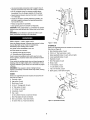
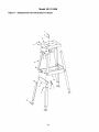
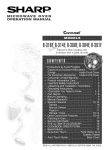
Figure 1 - Stand
EYESHIELD
Parts to be assembled should be located and accounted for
(See List and Figure 2).,
A 8ram Serrated washer, 2 each
B
#I0-24
x ¾" Pan head screw, 4 each
C Upper eyeshie]d
bracket,
2 each, (left and right)
Parts for stand and additional parts which need to be fastened to grinder, should be located and accounted
for before
D Lower eyeshield
bracket,
2 each
assembling
E
Eyeshield,
To be certain the grinding wheels have not been damaged in
shipping, strike the edges slightly with a metal object.. A ring-
F
6mm Fiat washer,
ing sound indfcates
a fracture
H ¼" Flat washer,
WARNING:
replace
serious
a good wheel, but a dull noise may signal
If you suspect
it immediately
injury
a wheel of being fractured,
Fractured
wheels
may shatter,
2 each
2 each
I
¼" Lock washer,
2 each
J
'/,-20 x ¾" Hex bolt, 2 each
K
Spark guard,
causing
STAND
2 each (left and right)
C
Parts to be assembled
(See List and Figure
A
Foot pad, 4 each
B
Leg section,
C Short
2 each
G Knob, 2 each
should
be located
and accounted
for
D
B
1)
8 each
brace, 2 each
D _f_-18 x _" Carriage
'
bolt, 24 each
E
_,_" Flat washer,
F
_/.,"=18 Hex nut, 24 each
24 each
G Long brace, 2 each
H Top, 1 each
1
8-1..25 x 45ram Hex bolt, 4 each (not shown)
J
8mm Flat washer,
K
8ram Lock washer,
L
8-1..25mm
8 each (not shown)
4 each (not shown)
Hex nut, 4 each (not shown)
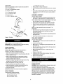
Figure 2 - Eyeshleld Assembly
TOOLREST
8-1.25mm
Parts to be assembled
(See List and Figure
A
should
be located and accounted
for
3).
_;_18 x 1_" Carriage
_"
D _"
E
Fiat washer,
bolt, 2 each
F _-18
on the top of the stand
holes in grinder's
base with siets on stand's
top.
,, Use 8-1..25 x 45mm
lock washers
stand top
6 each
-18 Hex nut, 2 each
Bracket,
Place grinder
,, Align mounting
B Tool rest, 2 each
C
,
Hex nut, 4 each
EYESHIELD
2 each
x ¾" Hex bolt, 4 each
hex bolts with 8mm flat washers,
Bmm
and 8-1 ..25ram hex nuts to secure grinder
to
ASSEMBLY
Refer to Figure 2, page 3
,, Fasten spark guard (K) to wheel guard using hex bolt (J),
lock washer (i), flat washer (H) and serrated washer (A)
NOTE: Serrated
washer
must be placed between
and wheel guard surfaces
,, Remove
for added
spark guard
stability
pan head screws (B) from eyeshie]d
assembly.
,, Mount left upper eyesh[eld bracket (C) to eyeshield (E)
using pan head screws (B) and lower eyeshield bracket
(U),,
NOTE: Left upper eyeshield
identification.
c
°
Figure 3 -Tool Rest
is stamped
"C' for
Slide knob (G) through 6mm fiat washer (F) and through
hole at top of spark guard (K) and fasten into upper
eyeshield
E
bracket
bracket
(C)
-
Locate eyeshield in desired
and tighten knob
-
Mount right eyeshield
TOOL
REST
position
assembly
for protecting
in a similar
operator
manner.
ASSEMBLY
Refer to Figure 3, page 3
°
Attach bracket
fiat washers
Refer to Figures
1, 2 and 3, pages 3 and 4.
° Tighten
(E) to wheel guard using hex bolts (F) and
(C)o
bolts finger tight
IMPORTANT:
Do not attempt assembly if parts are missing.
Use this manual to order replacement parts.
°
STAND
•
Slide tool rest (B) onto carriage
rest as shown in Figure 3.
,
Slide _" flat washer
carriage bolt..
ASSEMBLY
Refer to Figure
NOTE:
complete.
Then
bolts and nuts until assembly
tighten all fasteners
,, Place top (H) on the flat surface
,, Attach
4 leg sections
washers
is
securely.
up side down..
(B) to the top using carriage
(E) and nuts (F).
bolts (D), washers
Attached
carriage
°
Attach
4 leg sections
bolts (D), washers
the floor
to the floor
all bolts.
Stand should
not rock after all bolts are tightened°
GRINDER
bag with following
8-1.25
x 45mm
between
tool rest and
is tess than _,".
all nuts and bolts
Mount the opposite
side tool rest in a similar manner.
Refer to Figures 4 and 5.
on the fioor..
so all legs are contacting
and are positioned at similar angles
Locate
wheel
(B) to the braces using
foot pads (A) to the end of each leg..
= Adjust stand position
MOUNT
too_ rest so that distance
grinding
(E) and nuts (F)..
,, Turn the stand side up and position
NOTE:
nut finger tight
Position
-
bolt from the inside of tool
(C) and _I,"-18 hex nut (F) onto
•
• Secure
hole in tool
(E) and nuts (F)
remaining
,, Fully tighten
bolt (A) into square
(E)
• Tighten
bolts (D),
,, Attach 2 short braces (C) and 2 long braces (G) to the
ends of already assembled leg brackets using carriage
°
rest bracket
1, page 3.
Finger tighten
SIide _,1,-18x 1%" carriage
hardware:
Hex bolt, 4 each
8mm Flat washer,
8mm Lock washer,
8 each
4 each
POWER SOURCE
WARNING: Do not connect grinder to the power source until
all assembly steps have been completed,
The motor is designed for operation on the voltage and fre_
quency specified,, Normal loads will be handled safely on voltages not more than 10% above or below specified voltage,
Running the unit on voltages which are not within range may
cause overheating and motor burn-out. Heavy loads require
that voltage at motor terminals be no tess than the voltage
specified on nameplate.
• Power
supply
tothemotor
iscontrolled
byasingle
pole
locking
rocker
switchL
Remove
thekeytoprevent
unauthorizeduse,.
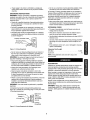
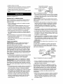
GROUNDING
INSTRUCTIONS
WARNING:
Improper connection of equipment grounding
conductor can result in the risk of electrical shock.. Equipment
should be grounded
electrical shock
•
while in use to protect operator
grounded
• This tool is equipped
with an approved
rated at 300V and a 3-prong
for your protection
Grounding
against
plug should
3-prong
Prope d yG rounded
3-Prong
3=conductor
cord
type plug (Figure 2)
shock hazards
be plugged
installed and grounded
as shown (Figure 4),
Grounding
grounding
directly into a properly
grounding-type
Outiet
receptacle,
_Fr=..,_=_...._-.-n
_
_
to 2-prong
grounding
adapter
is not permitted
,
wire system..
Many cover plate screws, water pipes and outlet boxes are
not properly grounded, To ensure proper ground, grounding
means must be tested by a qualified
EXTENSION
electrician
CORDS
• The use of any extension cord wit!cause some drop in
voltage and loss of powe_
= Wires of the extension cord must be of sufficient size to
carry the current and maintain adequate voltage,
• Use the table to determine the minimum wire size (A WG,.)
extension cord.
• if the extensioncord is worn, cut, or damaged in any way,
replace it immediately,
P}ug _.._.__
Extension Cord Length
Wire Size ......................................
AW, G
vides a path of least resistance
NOTE: Using extension cords ever 25 it, long is not
recommended.,
for electrical
Do not permit fingers
installing or removing
,, Plug must be plugged
shock
to touch the terminals
of
into matching
outlet that is propedy
let, have proper outlet installed
by a qualified electrician.
,, Inspect tool cords periodically, and if damaged,
repaired by an authorized service facility..
Green (or green and yellow) conductor
grounding wire. If repair or replacement
or pSug is necessary, do not connect
and yellow) wire to a live terminal,
a 2-prong
wa_l receptacle
in cord is the
of the electric
the green
assembly
cord
(or green
is encountered,
it must be
local codes and ordinances..
This work should
A temporary
3-prong
be performed
to 2-prong
grounding
Figure 5) is availabfe for connecting
ff it is properly grounded.
by a qualified
adapter
(see
plugs to a two pole outlet
Make Sure
Grounding
Lug \
This Is
Connected
To A Known
Adapter -_"_.._1
Ground
3 Prong
P_.
1_
2-Prong
Receptacle
Figure 5 - 2-Prong Receptacle with Adapter
DESCRIPTION
Craftsman 8" Variable Speed Bench Grinder is designed for
hand heed grinding, sharpening and cleaning operetiom
Equipped with a totaliy enclosed ball beadng motor. Armature
have
replaced with a properly grounded 3-prong receptacle
installed in accordance
with National Electric Code and
WARNING:
electrician.
16
from outlet.
installed and grounded in accordance with all local codes and
ordinances, Do not modify plug provided., ff it will not fit in out-
,, Where
on
permanent
electricat ground such as a properly grounded
water pipe, a properly grounded outtet box or a propedy
Up to 25 ft ..............................................................
plug when
in
Canada)
Where permitted, the rigid green tab or terminal
the side of the adapter must be securely connected to a
Do not remove or alter grounding prong in any manner, tn
the event of a maffunctton or breakdown, grounding pro-
WARNING:
•
(A 3-prong
• Use only 3-wire extension cords having 3-prong grounding
type plugs and 3-pole receptacles which accept the tool
plug
Prong _,
Figure 4 - 3-Prong Receptacle
•
Do not use a 3-prong to 2-prong grounding adapter unless
permitted by local and national codes and ordinances.
grounded
Check with a qualified electrician if grounding instructions
are not understood
or if in doubt as to whether the tool is
properly
•
from
•
is dynamically
balanced
for smooth
operation.
Motor housing is compact so long pieces of work can press
against both wheels without touching the motor frame..
Grinder operates at 3450 RPM and at variable speed in the
range of 2000 to 3300 RPMo includes adjustable tool rests,
spark guards
Gdnder
and eyeshie[ds
comes complete
with one wire wheel and one
grinding wheel installed plus two additional
and the stand.
grinding
wheels
WARNING:
Always wear safety glasses compfying with
United States ANSI Z87t
before commencing
power tool
operation.
catalog
Safety
glasses
are available
through
your Sears
SPECIFICATIONS
• Pressing too hard overheats the motor and prematurely
wears down the grinding wheels.
The grinder is assembled with motor and wiring installed as
an integral part of the tool,.
Horsepower
Voltage
120
.....................................................
5
.............................................
Rotation
(viewed
from left side)
2000-3300;
.................
diameter
bore ............................................
...................................................
s#,
Wheel
face .................................................
1"
.......................................
ALUMINUM
OXIDE
VITRIFIED
Grit ..................................
-
The grinding
ened.
•
Use slower wheel speed when sharpening
wilt destroy
rotate into object
to pull
being sharptempered
tools
the temper.
,, Dip work into a coolant regularly to prevent overheating
Overheating
can weaken metals.
61 lbs
WHEELS
,, Do not grind on the sides of grinding
#36 Coarse and _t60 Medium
are specifically
SWITCH
•
designed
wheels
unless
they
for that purpose.,
When starting the tool, let it run for one minute, Never start
the toot with a person in line with the wheel This includes
the operator.
To turn the grinder OFF, push the switch to the down position
NOTE: The grinder can be locked from unauthorized
locking the switch_.
wheel should
Overheating
,J To turn the grinder ON, pull the switch to the up position..
•
burrs from edge,
Deburring edge is done best by using the grinder
burr from edge across the bevel angle,
31"
..............................................
Gross weight
ONIOFF
8"
removing
-
Clockwise
Wheel
Note the original beveled angle on the item to be sharpened and try to maintain that angle, Sharpening
a cutting
edge requires
3450
Wheel
Stand height
-
Single
RPM ..............................................
wire wheel,,
O
60
Phase ...................................................
pressure when using
Excessive pressure causes over-bending of the wires and
heat build-up resulting in wire breakage, dulling and
reduced wheel life
Duty) .............................
.............................................................
Amperes
Hertz
(Continuous
• Avoid excessive
WARNING:
In normal
being removed,
use by
wire wheel operations,
such as burrs, scale,
the material
dirt, weld slag or other
residue, wilt fly off the wheel with considerable
force along
with wire filaments which break off due to fatigue,
To lock the switch:
•
Turn the switch to OFF position and disconnect grin der
from power source
•
Pu!] the key out, The switch cannot be turned
on with the
,, As wheels wear, toot rests should
the face of the wheels.,
key removed,,
NOTE: Should the key be removed from the switch at the ON
position, the switch can be turned off but cannot be turned on
-
again,,
•
To replace
key, slide key into the slot on switch
snaps
VARIABLE
°
To operate
SPEED
grinder
°
To operate
The speed
,, Replacement
3500 RPM
SWITCH
at full speed (3450 RPM),
(Key No., 59) completely
turn knob
counterclockwise.
Sharpening
and grinding operation can be done on the
right side of the grinder using grinding wheel
•
Cleaning of metal surfaces can be done on the left side of
the grinder using wire wheel
•
Keep a steady, moderate
keep it moving
Maximum
To loosen the nuts holding
wheel diameter
the
rated speed of
is 8".
the wheels,
disconnect
power
and push a wood wedge between the toot rest and the
wheel to keep the shaft from turning The threads on the
right side of the grinder (facing unit) are right hand; the
threads on the left side are left hand Tighten nuts securely
before operating
on the work piece and
at an even pace for smooth
be maintained,
must have a minimum
•
GRINDING
•
wheels
•
grinder at a slower speed turn knob clockwise,
is infinitely variable from 2000 to 3300 RPM
pressure
The gap between the wheel and the tool rest should not be
greater than 't,," When the wheels are worn to the extent
that the V,_,"maximum gap cannot
wheels should be replaced.,
until it
be positioned closer to
gdnding.r
6
the grinder
.
For grinding efficiency, wheels should be dressed periodically, especially if they become clogged from gdnding soft
metals,
•
Use grinding wheel dresser - 25282 to restore wheels to
original shape, (See recommended
accessories,
page I1.)
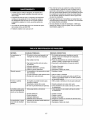
SYMPTOM
POSSIBLE
Grinder won't start
1, Blown line fuse or tripped circuit breaker
CORRECTIVE
CAUSE(S)
2., Low line voltage
wheel and
vibration
f, Improper mounting
accessories
Motor overheating
of grinder
6. Replace
or
will not operate
speed mode
and correct as needed
material
circuit
board
1. Remount
wheel out of balance
2. Dress wheels or replace
3. Improper
wheel mounting
3, Remount wheels, but rotate one wheel 90 ° with
respect to its previous position. Other wheei should
remain in its original position
I. Excess pressure required to grind material
Overl0ading due to binding
2 Defective
3 Defective
4 Defective
Grinder
variable
off and remove
2,, Grinding
2. Grinding on side of wheel
3, Motor not turning freely (without
Fuses are being blown
or circuit breakers tripped
power supply for voltage
3, Turn grinder
4., Replace switch
i 5, Replace capacitor
5_ Defective, blown capacitor
6., Defective circuit board
Excessive
I, If fuse is blown, replace with fuse of proper size., If
breaker tripped, reset it
F2, Check
3, Material wedged between
guard
4 Defective switch
ACTION
plug
cord
switch
5: Faulty ,internal widng
in 1 Defective variable speed switch
2 Defective sensor
3. Defective
circuit board
1. Dress wheel or replace
wheels
wheel with one of proper grit
2, Gdnd only on face of wheel
power)
3
Clean around
bearings
wheels
and shaft andlor
replace
1 Clean around wheefs and shaft and/or replace
bearings
2
3
Replace
Replace
4, Replace
plug
cord
switch
5. Contact authorized
1. Replace
switch
2. Replace
sensor
3. Replace
Sears Service
circuit board
Center
0
m
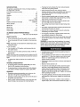
"0
0
f-
L.
o
tO
L.
_3
m
!
_3
E
OJ
u
o.
0J
rr
i
_D
OJ
=
im
U.
<
E
.!=
r_ZZ
9
_
_
,13
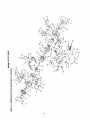
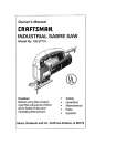
Model 351.211930
Figure
7 - Replacement
Parts Illustration
for Stand
9_
11
/
4
t0
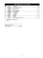
KEY
NO.
PART NO.
DESCRIPTION
1
STD835045
8-1 25 x 45mm
2
STD851008
8mm Flat Washer*
3
4
25282+00
STD533106
Top
_/o-18 x _" Carriage
5
STD852008
8mm Lock Washer"
6
STD840812
8-1,25mm
7
STD541031
_"-18
Hex Nut*
24
8
STD551031
_/." Flat Washer*
24
9
25283+00
Leg Section
8
10
11
25285.00
25284.00
Long Brace
Short Brace
2
2
12
25286+00
Foot Pad
2528800
Hardware
A
A
Standard hardware
Not shown
item available
QT_+
Hex Head Bolt*
4
8
1
24
Bolt*
4
Hex Nut*
4
4
Bag (Key Nos
1, 2 and 4 + 8)
locally
Recommended Accessories
A Wheel Dresser
11
1
ESMERILADORA
DE 8 PULGo
CON PLATAFORMA
ADVERTENCIA:
Para su propia seguridad, lea todas fas
instrucciones y las precauciones antes de opera,' la herramfenta.
PRECAUCION:
Siempre siga los procedimientos
de operaciSn
correctos, ta_ come se definen en este manual, aun cuando est_
familiarizado con e[ use de _sta e de otras herramientas simI-
Modelo No.
351.211930
lares Recuerde que, si no se tiene cuidado per aunque sea una
fracciSn de segundo, se puedan producir tesiones personates
graves.
PRECAUCION:
Lea este manual y siga las
Reglas de Seguridad y las lnstrucciones de
Operaci6n, antes de usar este producto per
primera vez.,
ESTE
PREPARADO
PARA
• Use ropa apropiada No use ropa suelta, guantes, cotbatas,
anil!es, pulseras u otras joyas qua puedan quedar cogidas
en las partes mSviIes de ta m_quina
= Use una cubierta
cabetlo largo.
protectora
• Use zapatos de seguddad
Ingles ......................................................................
2-6
Ilustrasi_n y Lista de Partes ...........................................
Garantfa ..............................................................
8-9
10
Reglas de Seguddad ...............................................
11-12
InstataciSn.............................................................
12-13
OperaciSn .................................................................
Mantenimiento ............................................................
13-14
14
GARANTIA
COMPLETA
HERRAMIENTA
DE
UN ANO
Use una m_.scara para la cara o una m_scara para el polvo,
si la operaciSn de lijado produce polvo.
°
Est_ alerta y piense claramenle. Nunca opera herramientas
mec_nicas cuando est_ cansado, intoxicado o cuando est_
tomando medicamentos qua causan somnoiencia.
fa_fara per causa de defectos en e]
en un lapse de un a_o a partir de
1-800-4-MY-HOME®
PARA
GRATUtTA DEL PRODUCTO
o
•
No use herramientas mec_nicas en ambientes pe[igrosos No
use herramientas mec&nicas en lugares h_medos o mojados.
No exponga las herramientas mec_nicas a la !luvfa
*
El _rea de trabajo debe estar iluminada adecuadamente.
•
Mantenga a los visitantes a una distancia
de trabajo.
-
Mantenga a los niSos fuera de] lugar de trabajo. Haga qua
su talter sea a prueba de nfSos Use candades, interruptores
principales o remueva las IJaves del interrupter para evitar el
use no intencionaf de las herramtentas mec_nicas
Estates, IL 60179
ADVERTENCIA:
Parte del polvo producido per e] lijado
mec,_nico, serrado, esmerilado, taladrado y otras tareas de construcciSn centiene sustancias qu_micas qua pueden ecasionar
c_ncer, malformaciones cong6nitas u otros daSos reproductivos.
S_lice cristatino proveniente
al de mamposterfa
•
Ars_nico y creme proveniente
de ladri!los, cemento
siempre
MANTENER
la herramienta
LAS
prudente del _.rea
HERRAMIENTAS
•
Desenchufe
•
Censulte el manual para informarse sobre los procedimtentos
de mantenimiento y ajuste espec{ficos
= Mantenga ta herramienta
operaci6n m_s segura
qu[micas son:
de pinturas con base de plomo.
•
EL
Mantenga el _ma limpia_ Las _reas de trabajo desordenadas
atraen accidentes
ES IMPORTANTE
,, Piomo proveniente
EJECUTAR
= Los cordenes de extensiSn deben tener una punta de conexiSn a tierra y los tres alambres del cord6n de extensfSn
deben set de] calibre correcto.
Esta garantia te otorga detaches legales especfficos y tambi_n
puede usted tener otros derechos que var_en de estado a estado.
Algunos ejemplos de estas sustancias
PARA
= Tiene que haber disponible un recept,_culo e!_ctdco adecuado
para la berramienta. El enchufe de ires puntas se tiene qua
enchufar directamente en un recept&culo de tres puntas
conectado a tierra correctamente.
(o su reemplazo si no se puede reparar la unidad). Esta garantia
no incluye partes fungibles, tales come l_mparas, bater_as,
o ruedas esmefitadoras y de cable
Sears, Roebuck and Co,,, Hoffman
AREA
•
PARA
Siesta herramienta se usa alguna vez para fines comerciales
de alquifer, esta garant(a es v&l]da Onicamente per 90 dfas a
partir de la fecha de compra.
DEL
TRABAJO
CRAFTSMAN
St esta herramienta Craftsman
material o en la mane de obra
la fecha de compra, LLAME at
SOLICITAR LA REPARACION
con suelas antideslizantes
qua cump]an con ANSI Z87.1 de
•
PREPARACION
14
..................................................
para el cabe!lo, para suietar el
Estados Unidos Los anteojos cordentes lienen solamente
lentes resistantes al impasto. NO son anteojos de seguridad.
11
Montaje .........................................................
IdentificaciSn de Problemas
o Use gafas de seguddad
10-11
Oesempaque ..................................................
ELTRABAJO
-
y otto materi-
tubricada
Remueva las herramientas
antes de inspeccionaria
y limpia para ebtener una
de ajuste. F6rmese el h_bito de
revisar para verificar si ]as herramientas de ajuste se hart
removide antes de encender la m_quina.
de madera qu_micamente tratada.
Et desgo debido a la exposiciSn de estas sustancias qufmicas
depende de ]a frecuencia con la cuaf realice este ripe de trabajo.
Para reducir la exposiciSn a estas sustancias qufmicas: trabaje
en un #,tea bien vent'Elada y utilice equipo de seguridad aprobado
Cuando trabaje con este tipo de herram}entas, utilice siempre
una m_scara para la cara o respirador adecuadamente ajustados, aprobados per OSHA/NIOSH
12
•
Mantenga todas las partes listas para funcionar Revise para
determinar qua ef protector u otras parles operar_n correctamente y har_n el trabajo que deben hacer
•
Revise para verificar si hay
verificar el alineamiento de
camien!o, roturas y montaje
pudiera afectar Fa eperaci6n
partes daSadas.. Revise para
ias partes movibles, si hay ataso cualquier otra condici6n que
de la herramienta
.
Para asegurarse qua las ruedas esmeriladoras no hayan sufrido
da5os durante el transporte, golpee los bordes ligeramente con
un objeto metal!co. Un sonido resonanle es indicaciSn de una
rueda en buen estado; sin embargo, un sonido sordo revela una
posible fractura+
Si hay una protecciSn o cualquier otra parte daFmda, tiene
que repararse correctamente o cambiarse, No haga reparaclones provisofias, (Use la lista de pades que viene inc+uida
para ordenar las partes de repuesto )
EL OPERADOR
DEBE
SABER
COMe
USAR
LA
ADVERTENCIA:
Si sospecha qua la rueda tiene una fraclura,
reempl_cela de inroad!ate, Las ruedas fracturadas se pueden
quebrar y producir lesiones graves
HERRAMIENTA
.
Use ta herramienta correcta para el trabajo, No fuerce la
herramienta o el accesorio, ni tos use para un trabajo para
el eual no han side diseSados
,, Desconecte
la herramienta
PLATAFORMA
Es necesario tocalizar y verificarFaspartes qua se van a montar
(consulte la Lista y la Figura 1)
euando cambie las ruedas rectifi-
cadoras+
•
•
Evite el arranque per accidentes Asegurese qua el interrupter
de la herramienta este_en la posiciSn OFF (apagado) antes de
enchufarla
No fuerca la herramienta Trabajar_ en ta forma m&s eficiente
a la vetocidad para }a eua_ se dise55
,, Mantenga fas manes alejadas de las partes mSviies y las
superficies
de esmeritado.
•
Nunca deje que una herramienta funcione sola Descon_cteia
y no se vaya hasta qua se detenga completamente
No irate de a[canzar
equi[ib rado.
demasiado
lejos Mant_ngase
firms y
•
Nunca se pare en la herramienta, Se pueden preducir lesienes
graves sila herramienta se inclina,
•
Conozca su herramienta, Aprenda la operaci6n de la herramienta, aplicacibn y limitaciones especificas,
°
Use los aecesorios que se recomienda, Consutte ]a p_gina
9 Si se usan accesorios incorrectos, se puede producir
desgo de leeiones persona[es
A
AFmohadil_a de pie, 4 en total
B
C
SecciSn para }as paras, 8 en total
Riostra coda. 2 en totat
D
Pemo de eoche de _Q-18 x %", 24 en total
E
Arandela plana de _",
F
Tuerca hexagonal de _A_"-18,24 en total
G
H
Riostra larga, 2 en total
Parte superior, 1 en total
!
Pemo hexagonal de 8.1,25 x 45 mm, 4 en total (no se muestra)
J
Arandela p]ana de 8 ram, 8 en totat (no se muestra)
K
L
Arandela de segurfdad de 8 mm, 4 en total (no se muestra)
Tuerca hexagonal de 8-1,25 mm, 4 en total (no se muestra)
24 en total
H
o No apriete demasiado la tuerca de la rueda. Gamble ta rueda
inmediatamente si est_ partida Use sSIo 1as pestafias qua
vienen con la esmeriladora.
°
Ajuste la distancia entre ta rueda y el soporte de _aherramienta para mantener un espacio libre de 1,6 mmo meno_+
= Maneje la pieza de trabajo correctamente
Cuando sea posible
use el soporte de ta herramienta para apoyar la pieza de tra+
baje durante la operaciSn de esmeritado. Apague la hertamienta si se atasca
.
Siempre use tas protecciones
o Limple el polvo del esmedtado
con frecuencia
y la protecciSn para los ojes,,
de debajo de Ia herramienta
PRECAUC|ON:
tPiense en la seguridadI La seguddad esuna
combinaciSn de sentido comun de1 operador y de estar a_erta
en rode memento cuando se est_ usando la herramienta.
ADVERTENCIA:
No trate de operar la herramienta hasta que
est_ comptetamente montada seg_n lae instrucciones
Figura 1 - Plataforma
PROTECCION
DE OJOS
Es necesario Iocalizar y verificar las partes qua se van a montar
(consuite _aLista y la Figura 2, p&gina 14)
Refi6rase las Figuras 1, 2 y 3, p;_ginas 13 y 14.
A
Arandela plana dentada de 8 ram, 2 en total
Verifique si han ocurrido daF_os durante el envfo. Si ha ocurrido
alg_n daSo, se debe entablar un reclamo con la compafiIa de
transportes. Verifique que fa orden est_ completa, Inforrne
inmediafamente al distribuidor si hay partes que faitan
B
Tornil_o de cabeza de ptaca, #I0+24 x %", 8 en total
C
Puntat de la protecciSn de ojos superior, 2 en total
(izquierdo y derecho)
D
E
PuntaE de la protecciSn de ojos inferior, 2 en total
ProtecciSn de ojos, 2 en total
Se incluyen dos ruedas adicionales:
F
Arandela plana de 6 mm, 2 en total
,, Rueda esmeriladoras de 8 pulg<, con granalla 36 (gruesa).
G PuF_o,2 en total
H Arandela plana de ¼", 2 en total
La esmeriladora
viene montada come una unidad
,, Rueda esmeritadoras
de 8 pulg, con granalla 60 (mediana)
Se debe ioealizar y verificar qua se hayan ineluldo las piezas adicionales y para la platatorma qua deben sujetarse en la esmeriladora antes de armada
13
I
Arandala de seguridad
J
K
Perno hexagonal de _-20 x _", 2 en total
ProteeciSn contra chispas, 2 en total (izquierdo
de ¼% 2 en total
y derecho)
de los soporles pare las pates previamente instalados mediante pernos de carruaje (D), arandelas (E) y tuercas (F).
C
B
\
J
•
Fije Eas 4 seccionee restantes de las paras (B) a los sopodes
mediante pernos de carruaje (D), arandetas (E) y tuercas (F).r
•
Fije Fas almohadiUas de pie (A) al extreme de cads pate
-
Vire ta plataforma basis arriba y colSquala
•
Ajusta la posiei6n de la pfataforma de manera qua redes las
pates toquen el piso y se encuentren colocadas en _ngulo
similar al piso.
-
Apriete bien lodes los pernos..
AVISO: La plataforma no debar& balancearse
hayan apratado lodes los pernos
K
MONTE
en el piso..
luego de qua se
LA ESMERILADORA
Ubique la botsa qua incluye el siguiente herraje:
Perno hexagonal de 8-1,25 x 45 mm, 4 en total
Arandela plane de 8 mm, 8 en total
Arandela de seguridad de 8 ram, 4 en total
Tuereca hexagonal de 8-1,25 ram, 4 en total
Figure 2 - Pmteccton de Ojos
SOPORTE
DE LA HERRAMIENTA
•
Coloque la esmeri_adora en la parte superior de la plataforma.
Es necesario locatizar y verificar las partes qua se van a reenter
(censu[te ta Usta y la Figure 3).
,, Afinee los orificios de montaje en la base de la esmedladora
A
Perno de coche de _-18 x I '_", 2 en total
•
B
Seporte
C
Arandela plana de N,", 6 en total
de la herramienta,
D Tuerca hexagonal de _'-18,
E Soporte, 2 en total
F
Perno hexagonal
con tas ranuras en la parte superior de la plataforma
2 en total
2 en total
Utilica pernos de cabeza hexagonal de 8-1.25 x 45 mm con
arandelas planes de 8 ram, arandetas de seguridad de 8 mm y
tuercas hexagona_as de 8-1 25 mm para asegurar la esmeriladora ala parte superior de ia plataforma
CONJUNTO
de 5;_-18 x ¾", ,1 en total
•
DE LA PROTECCION
DE OJOS
Asegure fa protecci6n contra ch}spas (K) a _a protecei_e de ta
rueda mediante el perno de cabeza hexagonal (J), la arandela
de seguridad (I), la arandera plane (H) y ta arandela dentada
(A).
AVISO: La arandela dentada debar& colocarse
protecciSn centre chispas y Eassuperficies
la rueda pare brindar mayor estabilidad
entre la
de la protecciSn de
• Remueva los torniIIos de cabeza de place (B) del conjunto de
la protecciSn de ojos
• Monte er punta_ de la protacci6n de ojos superior izquierdo (C)
en la protecciSn de ojos (E) usando los tornil{os de cabeza de
place (8) y el puntal de la protecciSn de ojos inferior (D)..
AVISO: El puntal de Ia profession de ojos superior izquierdo
viene estampado con la letra "L" pare identificaci6n
• Desiice la peri[la (G) a tray,s de Ja arandela ptana de 6 mm
(F) y a trav_s del agujero en la parte superior de la protacciSn
centre chispas (K) y aseg_reia en el soporta de la protecci6n
pare los ojos superior (C).
._..i D
Figure3 _Soportede la Herramienta
Refi_rase
,, Ce]oque la protecsi6n para los ojos en ]a ubicaci6n deseada
de mar=era qua pueda proteger al operador, y aprtete la
mani]ta
• Monte el conjunto de la protecciSn de ojos darecho de una
manera parecida..
las Figures 1, 2 y 3, p&ginas 13 y 14
PRECAUCION:
No trate de hacer el montaje si hay partes qua
fellah Use este manual pare ordenar partes de repuesto
INSTALACION
CON,JUNTO
DEL
SOPORTE
DE LA HERRAMIENTA
• Fije el soporte (E) ala protecci6n de la rueda mediante
de cabeza hexagona_ (F) y arandelas ptanas (C).
DE LA PLATAFORMA
pernos
CensuRe la Figure 1 en la p_gina 13
,, Apriate los pernos con la mane..
AVISO: Apr_ate los pernos y tuercas con los dedos haste qua
hays finalizado la tnstaiaciSn. Luego apriete firmemente redes los
sujetadores..
,, Deslice e_ perno de coche de _/,_18 x 1_" (A) en el orificie
• Celoque la parle superior (H) sobre la superficie
abajo.
cuadrado en et puntal dei soporle de la herramienta
plane boca
•
Fije las 4 secciones de tas pates (B) ala perle superior marlante pernos de carruaje (D), arandelas (E) y tuercas (F)
•
Fije 2 riostras cortas (C) y 2 riostras largas (G) a los extremes
(E).
• Deslice e_ soporte de la herramienta (B) al perno do carruaje
desde la parle interior del soporte de la herramienta seg_n se
indica en el Figure 3..
• Daslice la arandela plane de 5/_,. (C) y la tuerca hexagonal de
_1_,"-18(F) en el perno de coche
14
,, Apriete la tuerca con la mane.
•
Tomacordenle
Punta de conexi6n a tierra.,_.
,, Asegure lodes las tuercas y todos los pemos.
•
Monte el soporte de la herramienta
forma.
conectado
,,o,,ooo
Ponga el soporte de la herrarnienta de mode qua la distancia
entre 6ste y la rueda esmedtadora sea de manes de V_".
del lade opuesto
"_"
_.
II
de igual
3 puntas
__
Figura 4 - Receptdculo de 3 puntas
Refi_rase
MONTAJE
alas
f, No remueva ni altere la punta de conexiOn a tierra de ninguna
manera.. En el case de una faila o de una descarga disruptiva,
ia conexiOn a tierra proporciona el camino de manor resistencia al cheque el6ctrico.
Figures 4 y 5.
DE LA ESMERILADORA
ADMERTENGIA:
No perrnita qua los dedos toquen los terminales o el enchufe cuando se est&n instatando o removiendo del
tomacordente
Monte la esrneriladora en una supefficie horizontal sOlida (no
incfuye los articulos de ferreteHa). Si viene montada en un
pedestal de metal:
_, Alinee {os agujeros de montaje con los agujeros
dientes en el pedestal
•.
Insede un perno de cabeza hexagonal de ¼-20 x 1¼" con
la arandela plane a tray,s de la base de la esmedladora
-
A padir de la parle infedor del pedestal, ponga one arandela
plane de ¼" y una tuerca hexagonal de :,'_"-20 en el perno.
•
•
,, El enchufe se debe enchufar en el tomacorriente
correspon=
•
lnspeccione tos cordones de la herrarnienta periOdicamente y,
si est_n daOados, h_galos reparar per un servicio autodzado.
•
El conductor
Apdete haste qua fa base quede al ras con el pedestal
Use la segunda
tuerca en cada perno, y apri6tefa haste qua
•
•
Apriete los torniltos haste qua la base y la parle superior de!
banco est_n al ras
FUENTE
DE
Cuando se encuentra un recept;_culo de pared de 2 puntas, se
debe reemplazar per un recept_cuto de 3 puntas conectado a
tierra correctarnente e instalade de acuerde con los c6digos
y reglamentos det C6digo Nacional de Electdcidad y con los
cOdigos locales.
ADMERTENCIA:
tricista calificado.
ENERGIA
ADVERTENCIA:
No conecte la iijadora/esmefiiadora
ala
fuente de energfa sine hasta despuOs de qua se hayan
comple*tado lodes los pesos def montaje
Este trabajo debe set ejecutado
per un elec*
Se puede obtener un adaptador de conexiOn a tierra provisodo de 3 puntas a 2 puntas (yea la Figure 5, p_gina 13) pare
ceneclar los enchufes a un tomacordente bipolar, si est', ceneclade a tierra correctamente.
El motor ha side diseOado pare operar con el voltaje y la frecuencia especificados Las cargas normales se pueden rnanejar con
seguridad con voffajes de no m_s de 10% per sabre o bajo del
voltaje especificado. Si se hace luncionar fa unidad con voltajes
qua no eaton dentro de la game, se puede producir un calentamiento excesivo y quemarse el motor Las cargas pesadas exigen
qua el voltaje en los terminales del motor no sea manes qua el
voltaje especificado.
•
del cordon es et cable
y arnadllo) a un terminal cargado
en ta parle superior del banco de rnadera:
Usando los tornillos de madera de ¼ x 1¼" con las arandefas
planes debajo de las cabezas..
.
verde (o verde y amarillo)
de conexi6n a tierra. Si es necesario reparar o cambiar el cordon el_ctrice o el enchufe, no conecte el cable verde (o verde
tope contra la pdmera pare evitar qua se suellen debido ala
vibraci6n.
Monte fa esrnedladora
correspon-
diente, que debe estar instalado correctamente y conectado
a tierra seg0n lodes los cOdigos y reglarnentos locales. No
modifique el enchufe qua se proporciona. Si no calza en
el tomacordente, hags qua un electricista calificado instale
uno correcto.
Aseg0resa
qua est6
e=_---3., conectado a
TalOn de tierra\
Adaptador
_"_"__
Eno.ufede
El abaslecimiento de energt'a que vaal motor est_ controlado
con un interrupter osctlante de enctavamiento unipofar.
Remueva fa llave pare impedir el use no autorizado.
.,_-_
_
\\\
Jl una conexiOn
IIconocida
atie a
Recept_culo
de 2 puntas
Figure 5 - Recept_euto de 2 puntas con edaptador
INSTRUCClONES
ADVERTENCIA:
PARA
LA CONEXlON
Si se conecta incerrectamente
A TIERRA
el conductor
• No use un adaptador de conexi6n a tierra de 3 puntas a
2 puntas a manes qua sea permitido per los c6digos y
reglamentos locales y nacionales.
de conexiOn a tierra del equipo, se puede producir un riesgo de
cheque etOclrico. El equipe debe ester conectado a tierra mientras se est_ usando, pare proteger al operador centre un cheque
el_ctrico.
,, Si las instrucciones pare la conexi6n a tierra no se entienden
si se tienen dudes de qua la herramienta est_ conectada a
tierra correctamente, consulte a un elecldcista calificado.
•
Esta herramienta viene equipada con un cordon de 3 conductotes aprobado, con capacidad de 300 V y con un enchufe
de 3 puntas de! ripe de conexi0n a lierra (Figure 4) pare su
proteceiOn en centre de los peligros de cheque el6ctrico.
•
El enchufe de conexiOn a tierra se debe enehufar directa-
(En Canada, no se permite user un adaptador de conexiOn a
tierra de 3 puntas a 2 puntas ) En donde est_ permitido, la leng0eta verde n'gida o el terminal en el lade del adaptador debe
estar conectado firmemente a una conexiOn a tierra el6ctrica
o
permanente, tel come una tuberia de ague conectada a tierra
correctamenle, una caja de tomacorriente conectada a tierra
correctamenle o un sistema de cables canectado a tierra
correctamente
• Muchos de los tornitlos de Fa plancha de cubierta, fas tubefias
de agua y las cajas de tornacorriente no est_n conectados a
tierra correctamente. Pare asegurar una conexi6n a tierra
correcta, un electdcista calificado debe probar los medios
de conexiOn a tferra
mente en un recept&culo de conexi6n a tierra de 3 puntas,
conectado a tierra e instalado correctamente, come se
rnueslra (Figure 4)
15
CORDONES
DE EXTENSION
INTERRUPTOR
DE ON/OFF
(ENCENDIDO/APAGADO)
•
El use de cualquier cord6n de extensi6n
de voltaje y p_rdida de energfa.
producir_ cierla ca[de
°
Pare encender la esmeriladora, cambie la posici6n del interruptor a la posici6n superio_
•
Los cables del cordSn de extensiSn tienen que set del tamaSo
suficiente come pare conducir corriente y mantener el voltaje
adecuado,
•
Pare apagar la esmeriladora,
ala posiciSn inferior,
•
Use la tabla pare determiner
•
•
cambie la posiciSn deF interrupter
AVISO: Se puede bloquear el interrupter
autorizado de la esmeriladora.
el tama£_ominimo del cordSn
pare impedir et use no
de extensiSn (AW.,G)
Pare bloquear el interrupter:
Use cordenes de extensiSn de 3 cables, con enchufes del ripe
.
de conexiSn a tierra de tres puntas y recept_culos
res que acepten el enchufe de la unidad
Abra el interrupter
de alimentaci0n
.
Extraiga la Uave No se puede Itevar el interrupter ala posici6n
ON (encendido) sin la Ilave
Si el cordon de extensi6n est& desgastado,
de tripoia-
cortado o da_ado
la esmeriladora
de la fuente
ArIse: Si se extrae la Ilave con el interrupter en la posiciSn ON
(encendido), se puede Ilevar _ste ala posiciSn OFF (apagado)
pero no ala de encendido.
en aTguna forma, c&mbielo inmediatamente,
Longitud del cord6n de extensiSn
Tamale del cable ......................................................
A,,W G
Haste 7,62 m ...................................................................
Arise:
y desconecte
•
16
No se recomienda el use de cordones de extension
Pare volver a inserter la llave, desficela al interior de la ranura
del interrupter hasta que se acopte.
m_s
INTERRUPTOR
largos de 7,62 metros.
DE VELOCIDAD
°Para
operar la esmeriladora a velocidad ptena (3450 RPM),
gire la manilJa (Key No, 59) cornpletamente en sent!do contrade alas manecillas del refoj.
•
DESCRIPCION
La Esmeriladora de Banco de Voles!dad Variable de 8 pulg de
Craftsman ha side diseSada pare rlevar a cabo operaciones de
fimpieza, afilado y esmerilado manual, Est& equipada con un
motor con rodamienio de beta iotalmente encerrado. El conjunto
del indus!do se ha balanceado din_micamente pare que
proporcione un funcionamiento
m_,s uniforme,
Pare operar la esmeriladora a una voles!dad m_s lenta, gire la
man!lie en el sent!do de las manes!lies del refoj La velocidad
es infinitamente variable desde 2000 haste 3300 RPM
ESMERILADO
.
La operaci6n de afiiado y esmerilado puede Itevarse a cabo
en el lade derecho de la esmeriladora utilizando la rueda
esmedtadora
La caja del motor es compacta, Io cuat permite que las piezas
de trabajo largas puedan presionar centre ambas ruedas sin tecar
el bastidor del motor La esmeriladora tunciona a 3450 RPM y
•
La Iimpieza de superficies met_licas puede I|evarse a cabo en
el lade izquierdo de ta esmeriladora utilizando una rueda de
cable
a una ve!ecidad variable entre el margen de 2000 a 3300 RPM
Incluye soporles de herramienta ajustables, protecciSn centre
chispas y pretecciones para los oios,
_, Mantenga una presiSn uniforme y moderada en el trabajo y
mant_ngaia movi_ndose a una ve]ocidad pareje pare obtener
un esmerfiado parejo,
La esmeritadora ineluye una rueda de cable y una rueda
esmerifadora instalada, edemas de dos ruedas esmeriladoms
adicionales y la plataforma
•
Si se presiona en exceso, et motor se calierfia domes!ado
las ruedas rectificadoras se desgastan prematuramente.,
•
Evite presi6n excesiva cuando utilizando la rueda de cable. La
presi6n excesiva debla los filamentos y cause tricciSn resuitando en rompimiento excesivo de los _amentos, r_pida perdida
de afilado y reducci6n de Pavida de la rueda
a troves de su cat_loge de Sears.
•
Ftjese en el _nguto de biselado original en el articulo que se
va a afilar y irate de mantener ese _.ngulo, El afilamiento de
un borde de corte exige la remociSn de las rebabas de1 borde,
La esmerlladora est_ montada con un motor y el cableado ha
side instalado come una parle integral de la herramienta
•
La meier manera de remover las rebabas se Iogra sise usa
ia esmeriladora pare retiradas de! horde a trav_s del _ngulo
biselado.
•
La rueda rectificadora debe rotaren
afitando.
•
Utitice una ve]ocidad
AOMERTENClA:
Siempre use gafas de seguridacl que cumpfan
con ANSI Z87 1 de Estados Unidos (se muestra en el paquete),
antes de empezar a operar la herramienta el_ctrica, Puede
ebtener gafas de seguddad
ESPECtFICAClONES
Caballos de fuerza (servicio
continue)
...........................
'_
Voltaje .....................................................
120
Amperios .........................................................
5,0
Herlz .............................................................................
60
Fase ........................................................
RPM ...............................................
herramientas
el temple,,
Monof&sico
2000-3300;
3450
8"
Di_metro interior de la rueda ......................................
_"
Cara de la rueda ............................................
1"
Altura de la platatorma .....................................................
Peso note .................................................
RUEDAS VITRIFICADAS
Grano ............................
el objeto que se est,,
de rueda m_s lenta cuando alile
temptadas El sobreca[entamiento
destruir&
-
Sumerja el trabajo dentro de un enfriador regularmente pare
evitar que se cariente domes!ado. El calentamiento excesivo
puede debf[itar los metales.
•
No esmerile per los facies de las piedras de esmedl a menos
que est6n diseSadas especificamente pare este propSsito.
RotaciOn (visto desde e! lade izquierdo) ...... En et sent!do de las
maniffas del reloj
Di_metro de la rueda ........................................
y
• AI encender la herramienta, d_jela funcionar durante un minute. Nunca oncienda la herramienta cuando haya personas
parades en linea con ella, incluyendo a! propio operador
31"
61 LBS
ADVERTENCIA:
En operaci6nes normales de la rueda de
cable, el material que se remueve, come rebabas, escoria,
mugre, escoria de seldadura, y otro residues, se desprender,_n
de la rueda con fuerza considerable junto con a[ambres que se
rompen per fatiga,
DE OXIDO DE ALUMINIO
Grueso #36 y Mediano #60
16
• Pare seller los tuercas que sujetan los ruedas, desconecte
la energia el_ctrica y empuje una cuSa de madera antra el
soporte de la herram}enta y la rueda para impedir que el aje
gire. Los roscas del lade derecho de la esmeriladora (de frante
ala unidad) son de deracha; los roscas an el lade izquierdo
son de izquierda.. Apriete los tuercas an forma segura antes
de operar la esmariladora
• A madJda qua tas ruedas se desgastan, los soportas dala
herramiente deben quedar calocados m_s cerca de la cara
de los ruedas
,. El espacio libra entre fa rueda y el soporte de la herramienta
no debe ser mds grande de 1,6 mm. Cuando las ruedas se
han desgastada haste tal punto que no se puede mantener
el espacio libra mdximo de 1,6 ram, as precise cambiar las
ruedas
•
Los ruedas de repuesto deben tener una veloc[dad de capacidad nominal minima de 3500 RPM..
t
Et di_metro m_tx[mo de la rueda ee de 8".
• Pare Iograr eficiencia an el esmart{ado, ]as ruedas daben ser
reacondicionadas
pefi6dicamente,
sobretodo si son obstruidas
per meta}es blandos esmefilados.
,_ Use una alisadora de rueda de esmeriladora - 25282 pare
restaurar los ruedas ala forma o_inal. (Yea los accesodos
recomendados, p_gina 11 )
SINTOMA
CAUSA(S)
La asmeriladora no
1.. El fusible de la ifnea estd quemado o el
interrupter de circuilo sa ha disparado
1. Si el fusible est_ quemado, cdmbiela par uno dal
tamaffo correcto. Si el interrupter se ha disparado,
vu6ivala a ajustar
2 Bajo voltaja an fa ffnea
2. Revise el abastecimiento de corriente et6ctriea pare
verifiear et voftaje y corrfjalo segt_n sea necesario
arransa
3 Hay materiai acufiado
la protecci6n
Vibraci'6n axcesiva
entre la rueda y
4. Camb_e eEinterruptar
5.. Cambia er capacitor
1 La esmeriladora o los accesorios no est._n
bien montados
2 La rueda rectificadora est& dasbalancaada
1. Vu61valos a mentor
1,,
6. Reempiace
1.,
en el mode de vetacidad
variable
eI tablero de eircuito
2. Afile las nJedas o c_.mbielas
3 Vuelva a montar tas ruedas, pete rote una de 90 ° con
respecto a su posiciSn original La otra debe quedarse
en su posici6n original
Se roquiere una presi6n excesiva para
asmorilar el material
1. Afire la ruada o c_mbiala par otra de gran0 adecuado
Sobrecarga
debido a aferramiento
Enchufe defectuoso
Cord6n dafactuaso
4. Interrupter defactuosa
5. Cableada interne dofoctuoso
na opera
y ramueva el material
de la rueda incorrecto
2 Esmadle solamente en la care de la ruada
3 Limpie alrededor
los rodamientos
de los ruadas y del eje y/o cambie
I
de los ruedas y del eje y/o cambie
Limpie atrededar
toe rodamientos
2o Cambie el enchufe
3. Gamble el cord6n
3,,
La asmeriladora
la esmeriladara
5 Capacitor defoctuoso o quemado
6. Tablero de circuito defectuoso
Esmari_ado en el lade de la rueda
3. El motor no gira libremente (sin potencia)
;l.Os' ius'ibles est_,n quemm
dos o los interruptores de
circutta se hart disparado
3. Desconecte
4 Interrupter dafectuoso
3 Montaja
El motor so ca[ionta
damasiado
MEDIDAS CORRECTIVAS
POSIBLE(S)
4. Cambie el interrupter
5. Pdngasa en cantacto con el Centre de Servicio
Interrupter de valocidad variable defectuaso
2 Sensor defectuoso
11.. Reemplace el sensor
i 2. Reemptace
17
el tablero de circuito
Sears
NOTAS
18
NOTAS
19
Get it fixed, at your home or ours.
Your Home
For repair _ in your home " of all major brand appliances,
lawn and garden equipment, or heating and cooling systems,
no matter who made it, no matter who sold it!
For the replacement parts, accessories and
owner's manuals that you need to do-it-yours_.
For Sears professional
installation of home a ppliances
and items like garage door openers and water heaters.
1-800-4-MY-HOME
Ca!! anytime,
®
(1-800-469-4663)
day or night (US.A.
www,sears.com
For expert home solutions
and Canada)
www.sears.ca
advice: www.managemyhome.com
Our Home
For repair of carry-n items like vacuums, lawn equipment,
and electronics, call or go on-linefor
the location of your nearest
Sears
Parts & Repair
1-800-488-1222
(U.S.A.)
Call anytime,
www.sears.com
To purchase
a protection
1-800-827-6655
agreement
(U.S.A.)
Para pedir servicio de reparaci6n
a domicilio, y para ordenar piezas:
1-888-SU-HOGAR
Service
Center
1-800-533-6937
(Canada)
day or night
www.sears,ca
on a product
serviced
by Sears:
1-800-361-6665
Au Canada
(Canada)
pour service
en fran_;ais:
1-800-LE-FOYER
_
Mc
(1-800-533-6937)
www.sears.ca
(1-888-784-6427)
Sea/rs
® Registered Trademark t TM Trademark I s_ Service Mark of Sears Brands, LLC
® Marca Registrada / TMMama de F&brica / sM Marca de Servicio de Sears Brands,
MC
_D
Marque de commerce I
Marque d6pos&e de Sears Brands. LLC
LLC
© Sears
Brands,
LLC