1
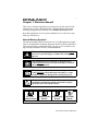
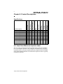
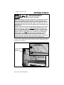
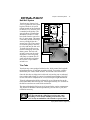
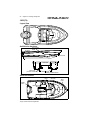
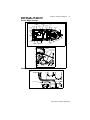
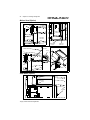
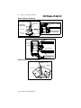
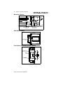
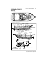
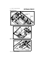
The information in this Owner’s Manual Supplement
relates to 1999 & 2000 Bayliner Trophy Fishing Boats.
Hull Identification Number___________________________________________
Engine Serial Number _______________________________________________
Engine Serial Number _______________________________________________
Hull Identification Number:
The Hull Identification Number (HIN) is located on the
starboard side of the transom.
Record the HIN and the
engine serial number in the
space provided above. Refer
to the HIN for any correspondence or orders.
STARBOARD
HIN LOCATION (TYPICAL)
TRANSOM
© 2000 Bayliner Technical Publications. All rights reserved.
No part of this publication may be reproduced, stored in any retrieval system, or transmitted
in any form by any means, electronic, mechanical, photocopying, recording or otherwise,
without prior written permission of Bayliner.
Printed in the United States of America.
General Notes
The material in this document is for information only and is subject to change without
notice. While reasonable efforts have been made in the preparation of this document to
assure its accuracy, Bayliner assumes no liability resulting from errors or omissions in this
document, or from the use of information contained herein. Due to our commitment to product improvement, Bayliner reserves the right to make changes in the product design, specifications, and equipment at any time without notice or obligation. Illustrations and/or photos
may show optional equipment. All Bayliner products meet or exceed USCG and/or NMMA
construction standarda. Manufactured with 1,1,1 Trichloroethane, a substance which harms
public health and environment during the manufacturing process by destroying ozone in the
upper atmosphere.
Proprietary Rights
This document discloses subject matter in which Bayliner has proprietary rights. The information and design disclosed herein were originated by and are the property of Bayliner.
Neither receipt nor possession thereof confers or transfers any right to reproduce, copy, alter
or disclose the document or any part thereof, any information contained therin, or to construct boats or any item from it, except by written permission from or written agreement
with Bayliner.
This document is to be returned upon request to Bayliner.
Contents
Chapter 1: Welcome Aboard!
Chapter 3: General Systems
1
Hazard Warning Symbols
5
2
Dealer Service
2
Boating Experience
2
Engine/Accessories Guidelines
2
Safety Standards
3
Qualified Maintenance
3
Proprietary Rights
3
General Notes
Electrical System
6 12-Volt DC System
7 Shore Power/110-Volt
AC System
9
Navigation and Interior Lights
9
Bilge Blower
10 Fuel System
10 Fuel Fills and Vents
10 Fuel Filters
11 Bilge Pump
13 Fresh Water System
Chapter 2: Product
Descriptions
13 Water Heater
4
Specifications
13 Alcohol or Alcohol/Electric
Stove (Option)
4
U.S. Coast Guard Maximum
Capacities Label
14 110-Volt AC/12-Volt Refrigerator
14 Portable Toilet
14 Marine Head with Holding Tank
15 Bait Well System
15 Trim Tabs
16 Depth Finder
16 Anchoring
16 Compass
17 Canvas Top Installation:
17 Center Console
18 Cuddy Cabin Models
Chapter 4: Drawings
& Diagrams
19 1703 (FR)
20 1802 (FJ)
21 1903 (FK)
22 2002 (FF)
24 2052 (FD)
Chapter 5: Wiring Diagrams
38 Shore Power
39 Single Engine
(Outboard), Typical
40 Twin Engine
(Outboard), Typical
41 Stern Drive, Typical
25 2352 (FV)
Limited Warranty
27 2503 (FM)
42 What Is Not Covered
29 2509 (FW)
42 Other Limitations
33 2802 (FH)
42 Your Obligation
1
Chapter 1: Welcome Aboard!
This Owner’s Manual Supplement was prepared to provide specific information about your boat. Read the Owner’s Manual and this supplement
carefully, paying particular attention to the Limited Warranty section.
Keep this supplement in a secure place and hand it over to the new owner
when you sell the boat.
Hazard Warning Symbols
The hazard warning symbols shown below are used throughout this supplement to call attention to potentially dangerous situations which could lead to
either personal injury or product damage. We urge you to read these warnings carefully and follow all safety recommendations.
This symbol alerts you to immediate hazards which WILL
cause severe personal injury or death if the warning is
DANGER ignored.
!
!
This symbol alerts you to hazards or unsafe practices
which COULD result in severe personal injury or death if
the warning is ignored.
!
This symbol alerts you to hazards or unsafe practices
which COULD result in minor personal injury, or cause
product or property damage if the warning is ignored.
!
This symbol calls attention to installation, operation, or
maintenance information which is important to proper
operation, but is not hazard-related.
WARNING
CAUTION
NOTICE
Fire and/or
Rotating Propeller Personal Injury
Hazard!
Explosion Hazard!
Hazard!
Open Flame
Hazard!
Trophy Owner’s Manual Supplement
2
Chapter 1: Welcome Aboard!
Dealer Service
Make certain that you receive a full explanation of all systems from the selling dealer before taking delivery of your boat. Your selling dealer is your
key to service. If you experience any problems with your new boat, immediately contact the selling dealer. If for any reason your selling dealer is
unable to help, you can call us direct on our customer service hotline:
360-435-8957 or send us a FAX: 360-403-4235
Boating Experience
If this is your first boat or if you are changing to a type of boat you are not
familiar with, for your own comfort and safety, please ensure that you
obtain handling and operating experience before assuming command of the
boat. Your selling dealer, national sailing federation or yacht club will be
pleased to advise you of local sea schools, or competent instructors.
!
WARNING
• A qualified operator must be in control of the boat at all
times.
• Do not operate your boat while under the influence of
alcohol or drugs.
Engine/Accessories Guidelines
Your boat’s engine (or engines) and accessories were selected to provide
optimum performance and utility. Installation of different engines or other
accessories may cause undesirable handling characteristics. Should you
choose to install different engines, or to add accessories that will affect the
boat’s running trim, have an experienced marine technician perform a safety
inspection and a handling test before operating your boat by yourself again.
Safety Standards
Your boat’s mechanical and electrical systems were designed to meet safety
standards in effect at the time it was constructed. Some of these standards
were mandated by law. All of them were designed to insure your safety, and
the safety of other people, vessels and property.
PERSONAL SAFETY HAZARD - Do not
allow anyone to ride on parts of the boat that
DANGER
were not designated for such use:
Sitting up on the seat backs, bow riding, gunwale riding, occupying the
transom platform or the aft sundeck cushions while underway is especially hazardous and will cause personal injury or death.
!
Trophy Owner’s Manual Supplement
Chapter 1: Welcome Aboard!
3
Please read the Owner’s Manual, warning labels and all literature supplied
with your boat for important safety standards and hazard information.
Qualified Maintenance
!
WARNING
To maintain the integrity and safety of your boat, only
qualified people should perform maintenance on, or in any
way modify; the steering system, propulsion system, engine
control system, fuel system, environmental control system,
or electrical system.
Failure to maintain these systems as designed could violate the laws in your
jurisdiction, and could expose you and other people to the danger of bodily
injury or accidental death. We recommend that you follow the instructions
provided in this supplement, the Owner’s Manual, the engine owner’s manual, and the accessory instruction sheets included with your boat.
Proprietary Rights
This document discloses subject matter in which Bayliner has proprietary
rights. The information and design disclosed herein were originated by and
are the property of Bayliner. Neither receipt nor possession thereof confers
or transfers any right to reproduce, copy, alter or disclose the document or
any part thereof, any information contained therein, or to construct boats or
any item from it, except by written permission from or written agreement
with Bayliner. This document is to be returned upon request to Bayliner.
General Notes
The information contained herein is subject to change without notice and is
not to be used in conjunction with sales or advertising, except as may be
expressly permitted in writing by Bayliner. Actual operating results will
vary depending on conditions and variables.
All Bayliner products meet or exceed USCG and/or NMMA construction
standards.
Due to our commitment to product improvement, we reserve the right to
change, without notice or other obligation, the specifications or other information contained in this publication.
Manufactured with 1,1,1-Trichloroethane, a substance which harms public health and environment (during the manufacturing process) by destroying ozone in the upper atmosphere.
Trophy Owner’s Manual Supplement
4
Chapter 2: Product Descriptions
Overall Legnth
Bridge Clearance
Bridge Clearance With
Hard Top or T-Top (Option)
Beam
Maximum Draft
Fuel Tank
Capacity (gal)
ater Tank
apacity (gal)
Holding Tank
Capacity (gal)
Specifications
1703 (FR) Trophy Center Console
17’ 1”
4’ 11”
N/A
6’ 11”
2’ 2”
27
N/A
N/A
1802 (FJ) Trophy Cuddy
18’ 0”
5’ 2”
N/A
7’ 6”
2’ 7”
40
N/A
N/A
1903 (FK) Trophy Center Console
18’ 11”
5’ 8”
6’ 8”
7’ 8”
2’ 7”
55
N/A
N/A
2002 (FF) Trophy Walkaround
20’ 1”
5’ 2”
7’ 10”
8’ 0”
2’ 7”
82
N/A
N/A
2052 (FD) Trophy Walkaround
21’ 7”
5’ 6”
7’ 3”
8’ 0”
2’ 11”
64
N/A
N/A
2352 (FV) Trophy Walkaround
25’ 5”
6’ 7”
8’ 1”
8’ 5”
2’ 10”
106
8
N/A
2503 (FM) Trophy Center Console
27’ 3”
6’ 2”
7’ 11”
8’ 5”
2’ 5”
105
N/A
N/A
2509 (FW) Trophy Cuddy
27’ 3”
6’ 7”
8’ 1”
8’ 5”
2’ 5”
147
8
N/A
2802 (FH) Trophy Cuddy
31’ 0”
7’ 5”
9’ 6”
9’ 9”
2’ 6”
240
30
30
Model Description
U.S. Coast Guard Maximum Capacities Label
The U.S. Coast guard requires boats less than twenty (20) feet in length to
have a Maximum Capacities Label stating the maximum horse power, the
maximum number of persons and the maximum weight the boat will handle
safely under normal conditions. The Maximum Capacities Label is typically
located near the helm.
Trophy Owner’s Manual Supplement
5
Chapter 3: General Systems
Electrical System
Read and understand the Electrical Section of the Owner’s Manual.
!
DANGER
EXTREME FIRE/EXPLOSION
and ELECTRIC SHOCK HAZARD!
• To minimize the risks of fire and explosion, NEVER install knife
switches or other arcing devices in the fuel compartments.
• NEVER substitute automotive parts for marine parts. Electrical,
ignition and fuel system parts were designed and made to comply
with rules and regulations that minimize risks of fire and explosion.
• DO NOT modify the electrical systems or relevant drawings.
• Fuel fumes are heavier than air and will collect in the bilge areas
where they can be accidently ignited. Visually and by smell (sniff
test), check the engine and fuel compartments for fumes or accumulation of fuel. Operate the bilge blower for at least four minutes
prior to engine starting, electrical system maintenance or activation of electrical devices.
• Only qualified personnel should install batteries and/or perform
electrical system maintenance.
• Insure that all battery switches are in the OFF position before performing any work in the engine spaces.
• Minimize the danger of fire and explosion by not exposing batteries to open flame or sparks. It is also important that no one smoke
anywhere near the batteries.
!
CAUTION
SHOCK and/or ELECTRICAL
SYSTEM HAZARD!
• NEVER disconnect the battery cables while the engine is running, as
this can cause damage to your boat’s electrical system components.
• The battery charging systems (alternator and, if applicable, battery charger) installed are designed to charge conventional leadacid batteries. Before installing gel-cell or other new technology
batteries, consult with the battery manufacturer about charging
system requirements.
Trophy Owner’s Manual Supplement
6
Chapter 3: General Systems
!
NOTICE
!
NOTICE
VOLTAGES - All boats use either 110-volt AC/60 Hertz,
240-volt AC/60 Hertz or 220-volt AC/50 Hertz single phase
systems, and 12-volt DC or 24-volt DC. Electrical distribution panels are labeled with voltage and frequency of AC
and DC.
Electrical connections are prone to corrosion. To deter
electrical problems due to corrosion, keep all electrical
connections clean and protect them with a quality spray-on
protectant such as Corrosion Guard®.
12-Volt DC System
Fuses, Circuit Breakers and Switches
TYPICAL ACCESSORY
CIRCUIT MASTER BREAKER
The engine is protected by a large circuit breaker on
the engine. The accessories on some models are
protected by a master circuit breaker usually located
near the battery. In addition, a fuse block for branch
accessory circuits is located behind the helm panel.
Wires are color-coded to indicate which accessory
each fuse services. Some items, such as radios and
bilge pumps, may be fused individually at the unit.
Autofloat switches are fused at the battery.
Some models are equipped with battery switches. Your Owner’s Manual
provides a general decription of battery switch function in the Batteries portion of the Electrical Section.
The crossover switch should be turned on only in emergencies. Leaving the switch ON can drain all onboard batteries.
CAUTION NEVER turn the battery switch(es) to the OFF position
while the engine is running, as this can damage your boat’s
electrical system.
!
PORT
(OR ONLY)
BATTERY
TYPICAL BATTERY SWITCHES
Trophy Owner’s Manual Supplement
STBD
BATTERY
Chapter 3: General Systems
7
Shore Power/110-Volt AC System
Your boat may be equipped with a 110 volt AC system. AC systems are
energized by dockside shore power. Standard dockside receptacles and
cords provided are rated at 30 amps. Since some shore installations do not
have 30 amp service, we recommend the purchase of 15 amp and 20 amp
adapters. Note: When 15 amp or 20 amp adapters are used there will be a
corresponding drop in supplied AC power.
!
DANGER
FIRE/EXPLOSION/SHOCK HAZARD!
• To minimize shock and fire hazard, DO NOT modify electrical systems
or relevant drawings. ONLY qualified personnel should install batteries and/or perform electrical system maintenance. DO NOT alter shore
power connectors and only use compatible connectors.
!
CAUTION
SHOCK/ELECTRICAL SYSTEM
DAMAGE HAZARD!
• Never connect dockside power to your boat outside North America
unless you have purchased the International electrical conversion
option, which is rated for 220-volt/50 Hertz. North American systems
are rated for 110-volt/60 Hertz power.
• Use double insulated or three-wire protected electrical appliances when
possible.
WATER HEATER DAMAGE HAZARD! DO NOT energize
the AC water heater electrical circuit until the heater is comCAUTION pletely filled with water. Even momentary operation in a dry
tank will damage the heating elements. Warranty replacements will not be made on elements or tank damaged in this
manner. The tank is full if water flows from the tap when the
hot water is turned on in the galley.
!
When using shore power, the simultaneous operation of several AC accessories can result in an overloaded circuit. It
NOTICE may be necessary to turn off one accessory while operating
another.
!
Trophy Owner’s Manual Supplement
8
Chapter 3: General Systems
!
WARNING
FIRE/EXPLOSION/SHOCK/
ELECTRICAL SYSTEM
DAMAGE HAZARD!
• Before connecting to shore power, all breakers and switches on the AC
master panel must be in the OFF position. Always attach the shore
power cord to the boat inlet first, then to the dock connection, thereby
avoiding accidental submersion of the “HOT” cord into the water. To
disconnect, first remove the dock connection before removing the cord
from the boat.
• Monitor the electrical control panel’s polarity indicators when connecting shore power to your boat. A GREEN light illuminating after the
power cord is plugged into the boat’s external power receptacle indicates acceptable electrical power in which you may energize the main
breaker switches. A RED light, however, indicates reversed polarity,
which could cause electrical system damage and possibly electrical
shock injuries. In this case, DO NOT energize the main breaker
switches. Instead, immediately disconnect the shore power cord (always
from the dockside outlet first) and notify marina management.
Check for proper polarity as outlined in the warning above. Activate the AC
system by first turning on the master breaker, then each individual component breaker as required.
SHORE POWER
LOCATION ON 2802 (FH)
DOCKSIDE PANEL
LOCATION ON
2802 (FH)
AFT
AFT
GALLEY VIEW
Trophy Owner’s Manual Supplement
Chapter 3: General Systems
9
Navigation and Interior Lights
We strongly recommend that you understand navigation light usage as outlined in the Navigation section of the Owner’s Manual. The navigation and
interior lights supplied with your boat are of top quality, but may periodically fail for a variety of reasons:
1.
2.
3.
4.
There may be a blown fuse (Replace the fuse in the switch panel).
The bulb may be burned out (Carry spare bulbs for replacement).
The bulb base may be corroded (Clean the base periodically and coat it
with non-conductive grease).
A wire may have come loose or may be damaged (Repair as required).
!
CAUTION
• Avoid the storage of gear where it would block navigation lights from view.
• Prolonged operation of cabin interior lights (overnight)
will result in a drained battery. Be conservative in the
use of battery power.
Bilge Blower
The bilge blower removes
fumes from the engine compartment and draws fresh air
into the compartment through
the deck vents.
TYPICAL
BLOWER
SYSTEM
To ensure fresh air circulation,
operate the bilge blower for at
least four minutes before
starting the engine, during
starting, and while operating
the boat below cruising speed.
Operation of the blower system is NOT A GUARANTEE that explosive fumes have been removed.
WARNING
If you smell any fuel, DO NOT start the engine.
If the engine is already running, immediately shut off the engine and
all electrical accessories. Investigate immediately. DO NOT obstruct
or modify the ventilation system.
!
Trophy Owner’s Manual Supplement
10
Chapter 3: General Systems
Fuel System
Fuel Fills and Vents
Fuel fills are located either on the aft deck or on the side decks adjacent to
the aft cockpit. Fuel receptacle caps are marked “GAS”. Fuel vents are normally located in the hull or transom below and in the same general area as
the fill. If you experience difficulty filling the fuel tank, check to see that the
fuel fill and vent lines are free of obstructions and kinks.
Fuel Filters
Fuel filters should be replaced periodically to ensure that they remain clean
and free of debris. A fine mesh screen filter is located on the fuel pickup
tube. An additional filter, when supplied by the engine manufacturer, is
installed on the engine.
Consult your selling dealer or local marina concerning fuel additives that
help to prevent fungus or buildup in your fuel tanks.
TYPICAL FUEL SYSTEM
FUEL TANK
DECK FITTING,
FUEL FILL
FUEL TANK VENT
FUEL FEED
HOSE
!
WARNING
!
FIRE/EXPLOSION HAZARD - It is very important that the fuel system be inspected thoroughly
the first time it is filled and then at each subsequent
filling. For your safety and the safety of your passengers, the fueling instructions in the Owner’s
Manual must be followed.
Avoid the storage or handling of gear near the fuel lines,
fittings and tank.
CAUTION
Trophy Owner’s Manual Supplement
Chapter 3: General Systems
11
Bilge Pump
Your boat is equipped with one
or more impeller-type bilge
pumps. They are controlled by
a switch on the dash panel,
which should be activated
whenever water begins to
accumulate in the bilge. Some
models will also have an automatic bilge pump switch
(“autofloat switch”) mounted
next to the bilge pump. This is
a float-type switch that will
activate a bilge pump automatically whenever the bilge water
accumulates above a pre-set
level. It is wired directly to the
battery so it will normally
function even when the boat is
completely shut down and
unattended, such as when the
boat is moored at a marina.
TYPICAL BILGE PUMP SYSTEM
TRANSOM
FLOAT
SWITCH
BILGE
PUMP
HOSE
THRU-HULL
Maintenance
Operation of the bilge pump should be checked often. To check the bilge
pump, activate the dash-mounted switch and verify that water in the bilge is
pumped overboard. If bilge water is present and the pump motor is running
but not pumping, inspect the discharge hose for a kink or collapsed area. If
no problems are found, check the bilge pump housing for clogging debris:
To remove the power cartridge:
1.
2.
TAB
FIN
Lift the tab while rotating the
fins counter clockwise and lift
out the power cartridge (Fig. 1).
Clear the housing of debris.
To reinstall the power cartridge:
1.
Make sure the “O” ring is properly located and coat the “O”
ring with a light film of vegetable oil or mineral oil (Fig. 2).
FIG. 1
Trophy Owner’s Manual Supplement
12
Chapter 3: General Systems
2.
Align the two cams on either
side of the power cartridge with
the two slots on the outer housing. Press the power cartridge
into the housing and twist clockwise. Ensure proper reinstallation by attempting to twist the
fins counter clockwise without
lifting the tab. The cartridge
should stay in place.
If applicable, the autofloat switch
should also be checked often for
proper operation. Lift the float by
turning the plastic insert, where the
wires enter the housing, 1/4 turn
counter clockwise (Fig. 3).
LIGHT FILM
“O” RING
OF OIL
POWER
CARTRIDGE
FIG. 2
As the float is lifted, the bilge pump should turn on. If lifting the float does
not turn the pump on, check the inline fuse. If the fuse is good but the
switch does not work, it may indicate a bad switch or possibly a low battery.
TYPICAL FLOAT SWITCH
FLOAT
DETAIL
FIG. 3
FLOAT
PLASTIC
INSERT
ON POSITION (UP)
OFF POSITION (DOWN)
!
NOTICE
Discharge of oil, oil waste or fuel into navigable waters is
prohibited by law. Violators are subject to legal action by
the local authorities.
Trophy Owner’s Manual Supplement
Chapter 3: General Systems
13
Fresh Water System
Your boat features a pressure-type (demand) fresh water system. This system operates when the pump switch, located near in the galley, is turned
ON. Turn the pump switch OFF when the boat is not in use and when the
water tank is empty.
Stored water can become stagnant and distasteful. Pump the water tank dry
before leaving your boat unattended for long periods of time. Occasionally
you may want to disinfect your water system. Ask your selling dealer about
available treatments and procedures.
Your boat may be equipped with a shower. Please read and follow the manufacturer’s operating instructions supplied in your baot’s owner’s packet.
Water Heater
Your boat may feature a water heater. Please refer to the owner’s packet for
manufacturer’s operating instructions. The water heater is connected to the
AC power system. If your boat is equipped with optional freshwater engine
cooling, the coolant from the closed engine cooling system may be circulated through the hot water tank for heating of potable water.
WATER HEATER DAMAGE HAZARD! DO NOT energize
the AC water heater electrical circuit until the heater is
CAUTION completely filled with water. Even momentary operation in a
dry tank will damage the heating elements. Warranty
replacements will not be made on elements or tank damaged in this
manner. The tank is full if water flows from the tap when the hot water
is turned on in the galley.
!
Alcohol or Alcohol/Electric Stove (Option)
Your boat may feature an alcohol or alcohol/electric stove. Manufacturer’s
operating instructions can be found in the boat’s owner’s packet. Carefully
read the operating instructions before using the stove.
!
Reduce the possibility of fire by removing all combustible
materials away from the stove before/during use.
WARNING
Trophy Owner’s Manual Supplement
14
Chapter 3: General Systems
110-Volt AC/12-Volt Refrigerator
Your boat may feature a 110-volt AC/12-volt DC refrigerator. Please refer
to the manufacturer’s instructions supplied in your boat’s owner’s packet.
The refrigerator operates on 12-volt DC power unless the 110-volt AC system is hooked up to shore power and the AC refrigerator breaker is ON.
In less than 24 hours, the refrigerator can render a 100-amp
battery useless for engine starting. When operating on 12-volts,
it is advised that the cold setting not be set higher than two (2).
NOTICE It is also advisable to turn off your refrigerator at night or
when not in use. If you are going out for more than a day and
cannot connect to dockside power, plan to run the engine each day to
maintain a charged battery.
!
Portable Toilet
If your boat features a portable toilet, carefully read and follow the manufacturer’s operating instructions supplied in your owner’s packet.
Marine Head with Holding Tank
Your boat may come equipped with with a marine head and holding tank.
Be sure to follow the manufacturer’s operating instructions included in the
boat’s owner’s packet.
Seawater is used to flush waste from the toilet into the holding tank. The
holding tank is plumbed to a waste fitting on the deck for use at a dockside
pump-out station, and to a macerator pump so that waste may be pumped
overboard (where regulations permit). The switch for the macerator is usually located at the helm station.
If at any time you are unable to pump water into the bowl, the probable
cause is debris in the pump diaphragm. To remedy this, shut the inlet seacock and dismantle the pump. The pump is generally held together with six
screws. The design is simple and the problem will be obvious when the
pump body is split open.
To winterize the toilet, shut off the intake valve and pump until the bowl is
dry. Remove the drain plug in the base and pump again to remove all water.
Do not fill the bowl with antifreeze. The inlet seacock should be left closed
while the boat is underway, or whenever the boat is left moored in the water.
Trophy Owner’s Manual Supplement
Chapter 3: General Systems
15
Bait Well System
Your boat may feature a bait
well. A typical bait well system
begins with the (1) hi-speed
pickup located on the underside
of the hull. A (2) seacock valve
is attached to the pickup. The
seacock allows for immediate
shutdown if needed. A water
hose leads from the seacock to
the (3) water pump. This pump
is normally located in the bilge
area or possibly higher in a
storage area. The water continues from the pump to the aerator valve and into the bait well.
Typically bait wells have an
overflow stand pipe and a full
drain system. The bait well
switch is on or near the main
dash panel. The water pump
will pump a constant flow of
water into the bait well when
the seacock is open and the
switch is on.
1
2
3
TO
AERATOR
VALVE
TYPICAL BAIT WELL
PICKUP SYSTEM
BAIT WELL
STAND PIPE
DRAIN
AERATOR
VALVE
REMOVE STAND PIPE
TO COMPLETELY
DRAIN BAIT WELL
TYPICAL BAIT WELL
DRAIN SYSTEM
Trim Tabs
Your boat may come equipped with trim tabs, which control the longitudinal and lateral trim of your boat at cruising speeds. Two rocker switches
identified by the words “BOW DOWN” are located at the helm station.
Once the best bow cruising trim is achieved, activate the port or starboard
trim switches individually to correct for unequal lateral loading. DO NOT
use the trim tabs to compensate for excessive unequal weight distribution.
Trim tab adjustment should be performed by several short touches to the
trim button rather than one long one. Allow approximately five seconds for
the hull to react between each switch activations.
The trim tab hydraulic fluid reservoir is located in the engine compartment.
The fluid level should be checked periodically (at least once a year) and
refilled as necessary.
!
WARNING
Improper use of trim tabs may cause loss of control. DO
NOT use trim tabs in a following sea as they may cause
broaching or other unsafe handling characteristics. DO
NOT let anyone unfamiliar with trim tabs to operate them.
Trophy Owner’s Manual Supplement
16
Chapter 3: General Systems
Depth Finder
Your boat may come equipped with a depth finder. The depth finder comes
with its own owner’s manual. We suggest that you read it carefully before
using the unit.
DO NOT use the depth finder as a navigational aid to prevent
collision, grounding, boat damage or personal injury. When the
WARNING boat is moving, submerged objects will not be seen until they
are already under the boat. Bottom depths may change too
quickly to allow time for the boat operator to react. If you suspect shallow
water or submerged objects, operate the boat at very slow speeds.
!
Trophy models not equipped with depth finders may have a tube laminated
into the hull for installing a depth finder transducer. The tube goes though
bulkheads which serve as fuel vapor barriers, so both ends of the tube have
been sealed. To install a transducer, pull the sealed ends off the tube and use
the string inside to pull the tranducer cable through. After pulling the cable
through, you MUST reseal both ends of the tube to ensure it is vapor-tight.
!
WARNING
Failure to reseal the transducer routing tube after removing the factory installed seals can cause fire, explosion and
possible injury or death.
Anchoring
We strongly recommend that you read and understand the Anchoring section of the Owner’s Manual.
!
WARNING
FLOODING AND SWAMPING HAZARD - Never anchor
by the stern alone--there is less freeboard and flooding or
swamping is more likely to occur. When using only one
anchor, secure the anchor line to the bow cleat or bow eye.
Compass
Your boat may come equipped with a compass. Carefully read and follow
the manufacturer’s calibration and operating instructions provided in the
owner’s packet.
Trophy Owner’s Manual Supplement
Chapter 3: General Systems
17
Canvas Top Installation:
Center Console
1.
2.
3.
4.
5.
6.
Attach end eyes of main bow (A) to aft deck hinges (B) and secure
with pin.
Push bimini to upright position and connect black plastic clip on end of
hold-down strap (C) to chrome eye straps (D) to temporarily hold
bimini top in place.
Attach fwd brace (E) to fwd deck hinge (F) and secure with pin.
Attach side brace (G) to the quick release jaw slide on secondary bow
(H) and secure with pin.
Adjust jaw slides, if needed, to obtain a tight bimini top. Tighten set
screws to hold bimini in place.
Tighten hold down straps (B) at forward end of bimini top.
Trophy Owner’s Manual Supplement
18
Chapter 3: General Systems
Cuddy Cabin Models
J
H
I
A
D
E
C
B
F
G
1.
2.
3.
4.
5.
6.
Attach end eyes of main bow (A) to aft deck hinges (B) and secure
with pin.
Attach fwd brace (C) to secondary bow (D). Insert end eye of aft brace
into aft bow hinge (E) and secure with pin.
Attach aft brace (F) to main bow (A). Insert end eye of aft brace into
aft bow and hinge (G) and secure with pin.
Make canvas taut by pulling aft and down on aft side of bimini top
while securing aft brace jaw slide (H). Also pull forward and down on
the fwd side of the bimini top while securing fwd brace jaw slide (I).
Tighten top straps (J), if needed, by adjusting the buckle slide.
If additional canvas (i.e. side curtains, slant back cover or camper
cover) is to be installed, it should be secured to the top canvas before
final adjustment. Like the top, the additional canvas should be smooth
and taut.
Trophy Owner’s Manual Supplement
19
Chapter 4: Drawings & Diagrams
1703 (FR)
Layout View
Hull Exterior View
BILGE PUMP
DRAIN
STARBOARD HULLSIDE
BOW EYE
TRANSOM
STERN EYES
SCUPPER, TYP.
PORT & STBD
GARBOARD DRAIN
Hull Wire Routing
BATTERY
CONSOLE
STERN
LIGHT
Trophy Owner’s Manual Supplement
20
Chapter 4: Drawings & Diagrams
1802 (FJ)
Layout View
Hull Exterior Hardware
BLGE PUMP
DRAIN
FISH LOCKER
DRAIN
STBD HULLSIDE
BOW EYE
TRANSOM
STERN EYE
(TYPICAL PORT/STBD)
GARBARD DRAIN
Electrical Harness
DOME
LIGHT
STERN
LIGHT
SUMP
Trophy Owner’s Manual Supplement
WIPER
(OPTION)
BOW
LIGHT
Chapter 4: Drawings & Diagrams
21
1903 (FK)
Layout View
Hull Exterior Hardware
AFT BILGE
PUMP DRAIN
BAIT WELL
DRAIN
BOW STORAGE
DRAIN
STBD HULLSIDE
BOW
EYE
AFT DECK DRAINS
(TYPICAL PORT/STBD)
TRANSOM
GARBOARD
DRAIN
STERN EYE
(TYPICAL PORT/STBD)
Wire Harness Routing
BOW
LIGHT
DECK HARNESS
CONSOLE
COURTESY
LIGHTS
SUMP
PUMP
AERATOR SEACOCK
GROUND
PUMP
FUEL TANK
SENDER
CONSOLE
BATTERY
STERN LIGHT
ENGINE
GARBOARD
DRAIN
GROUND
HULL HARNESS
BILGE
PUMP
Trophy Owner’s Manual Supplement
22
Chapter 4: Drawings & Diagrams
2002 (FF)
Layout View
step
Hull Exterior Hardware
FISHWELL
DRAIN, TYP.
PORT & STBD.
BILGE
DRAIN
FUEL TANK
VENT
BAIT WELL
DRAIN
STARBOARD HULLSIDE
DECK DRAINS
(TYPICAL
PORT/STBD)
TRANSOM
STERN EYE
(TYPICAL PORT/STBD)
Trophy Owner’s Manual Supplement
GARBOARD
DRAIN
TRIM TAB
(TYPICAL
PORT/STBD)
Chapter 4: Drawings & Diagrams
23
Deck & Bilge Harness
STERN
LIGHT
COURTESY
SPEAKER
LIGHT
SHIFTER
FUEL
FISH WELL
KILL
GROUND
PUMP
SWITCH
DASH
PLUG
WIPER
COMPASS
HORN
BILGE
PLUG
STERN
LIGHT
ENGINE
PLUG
BOW
LIGHTS
ACCY
BREAKER
FISH WELL
PUMP
INTERIOR
LIGHT
STEREO
SPEAKER
WIPER
ANTENNA
WIRE
COURTESY
LIGHT
BILGE
HARNESS
PLUG
TO BILGE PUMP
& FLOAT SWITCH
TO
BAIT WELL
PUMP
TO FUEL
SENDER
Head Pump-out (Option)
PORTA-POTTY
VENT
PORTA-POTTY
Trophy Owner’s Manual Supplement
24
Chapter 4: Drawings & Diagrams
2052 (FD)
Layout View
rod holder
step
Hull Exterior Hardware
BAIT WELL DRAIN
FUEL VENT
BILGE
DRAIN
FISHWELL
DRAIN, TYP.
PORT & STBD
DECK DRAINS
(TYPICAL PORT/STBD)
TRANSOM
STARBOARD HULLSIDE
GARBOARD
DRAIN
STERN EYE
(TYPICAL PORT/STBD)
TRIM TAB (OPTION)
(TYPICAL PORT/STBD)
Electrical Harness Routings
ENGINE
PLUG
BILGE
PLUG
STBD.
FISHWELL
PUMP
TRIM
PUMP
BAIT
WELL
PUMP
STBD.
COURTESY
LIGHT
PORT
FISHWELL
PUMP
BLOWER
FUEL
GROUND
STERN
LIGHT
STBD.
SPEAKER
BUSS
BAR
SHIFTER
KILL
SWITCH
PORT
COURTESY
LIGHT
DASH
PLUG
BILGE
HARNESS
PLUG
TRANSOM
STBD.
WIPER
PORT
SPEAKER
STEREO
ANTENNA
WIRE
COMPASS
LIGHT
INTERIOR
LIGHT
HORN
PORT
WIPER
PORT
BOW
LIGHT
Trophy Owner’s Manual Supplement
STBD.
BOW
LIGHT
BILGE
PUMP &
FLOAT
SWITCH
TO FUEL
SENDER
Chapter 4: Drawings & Diagrams
25
2352 (FV)
Layout View
Hull Exterior Hardware
HOLDING
BLOWER VENTS
TANK VENT
AFT BILGE (TYP. PORT/STBD)
DRAIN
MARINE HEAD (OPTIONAL)
(OPTIONAL)
GALLEY WATER
TANK VENT
STBD HULLSIDE
BOW EYE
FUEL TANK VENT
AFT SUMP PUMP
OUT (PORT SIDE)
MACERATOR
(OPTION)
FWD
BILGE PUMP
GALLEY
SINK DRAIN
TRANSOM
FUEL
FILL
TRIM TABS
(TYP. PORT/STBD)
DECK DRAINS
(TYP. PORT/STBD)
STERN EYE
(TYP. PORT/STBD)
GARBOARD DRAIN
Deck Harness Routing
TRIM PUMP
COURTESY
LIGHT
SPEAKER
DASH PANEL
FWD HULL
HARNESS
COMPASS
SHIFTER
WIPER
HORN
BILGE HARNESS
FUEL TANK
BOW LIGHT
STERN
LIGHT
ENGINE
SPEAKER
COURTESY
LIGHT
CABIN LIGHTS
CABIN LIGHT
STEP LIGHT
Trophy Owner’s Manual Supplement
26
Chapter 4: Drawings & Diagrams
Marine Head (Option)
HOLDING
TANK
MACERATOR
PUMP
TANK VENT
THRU-HULL
DECK WASTE
FITTING
SEACOCK
TANK VENT
THRU-HULL
V-BERTH VIEW
HEAD
SUMP
BOX
HEAD
Raw Water (Option)
WASHDOWN
OUTLET
WASHDOWN
PUMP
SEA
STRAINER
Trophy Owner’s Manual Supplement
Chapter 4: Drawings & Diagrams
27
2503 (FM)
Layout View
Hull Exterior Hardware
STBD HULLSIDE
BILGE PUMP
DRAIN
FISH WELL
DRAIN
SUMP BILGE
PUMP DRAIN
TRANSOM
DECK DRAINS
(TYPICAL PORT/STBD)
TRIM TABS
(TYPICAL PORT/STBD)
GARBOARD
DRAIN
Wire Harness Routing
STERN
LIGHT
TO CONSOLE
BOW
LIGHT
SUMP
PUMP
UNDERSIDE OF
DECK VIEW
COURTESY
LIGHTS
GARBOARD TO BILGE
DRAIN
PUMP
GROUND
SEACOCK
GROUND
CONSOLE
HULL
TOP VIEW
TO
MOTOR
FUEL TANK
SENDER
BATTERY
AERATOR
PUMP
Trophy Owner’s Manual Supplement
28
Chapter 4: Drawings & Diagrams
Water Systems (Options)
WATER FILL
DECK FITTING
WATER TANK
VENT THRU-HULL
TO DECK
FRESH WATER
SYSTEM (OPTION)
SEA STRAINER
WATER TANK
PUMP
RAW WATER WASHDOWN
SYSTEM (OPTION)
TO WASHDOWN
ON DECK
FRESH WATER
PUMP
Fish Well/Bait Well Sump System
FROM FISHWELL
SUMP BOX
FLOAT
SWITCH
FROM AERATOR TANK
BILGE
PUMP
FROM FWD BILGE
FROM FISHWELL
TO THRU-HULL
Head Pump-out System (Option)
TO WASTE
DECK FITTING
TANK VENT
THRU-HULL
PORTA-POTTY
Trophy Owner’s Manual Supplement
Chapter 4: Drawings & Diagrams
29
2509 (FW)
Layout View
Hull Exterior Hardware
MACERATOR
DRAIN (OPTION)
FWD BILGE
PUMP DRAIN
WATER
TANK VENT
STBD HULLSIDE
GALLEY SINK DRAIN
AFT BILGE
PUMP DRAIN
HOLDING TANK
VENT (OPTION)
FISHWELL
SUMP DRAIN
PORT HULLSIDE
TRANSOM
DECK DRAINS
(TYPICAL PORT/STBD)
TRIM TAB
(TYPICAL PORT/STBD)
GARBOARD
DRAIN
Trophy Owner’s Manual Supplement
30
Chapter 4: Drawings & Diagrams
Deck Hardware
ENLARGED VIEW
WATER FILL
MARINE HEAD
PUMP OUT
DECK FITTING
(OPTION)
Deck Harness
BILGE
HARNESS
TRIM PUMP
FWD HULL
SHIFTER
HARNESS
DASH PANEL
COURTESY
LIGHT
SPEAKER
COMPASS
WIPER
HORN
BOW
LIGHT
ENGINE
FUEL
TANK
STERN
LIGHT
SPEAKER
COURTESY
LIGHT
CABIN
LIGHT
STEP LIGHT
CABIN LIGHT
Fishwell Drain System
THRU-HULL
BILGE PUMP
SUMP BOX
FLOAT SWITCH
Trophy Owner’s Manual Supplement
Chapter 4: Drawings & Diagrams
31
Bait Well Pick-up System
HIGH SPEED
PICK-UP
BAIT WELL
PUMP
PUMP TO
AERATOR
TO BAIT WELL
TANK
Galley Water System
HAND PUMP
TANK VENT
THRU-HULL
WATER
TANK
WATER FILL
DECK FITTING
HOSE COVER
Marine Head (Option)
HOLDING
TANK
SUMP
BOX
HEAD
SEA
STRAINER
HEAD
HOLDING TANK
VENT THRU-HULL
Trophy Owner’s Manual Supplement
32
Chapter 4: Drawings & Diagrams
Macerator (Option)
MACERATOR
PUMP
DECK WASTE
FITTING
TANK VENT
THRU-HULL
Raw Water (Option)
WASHDOWN
OUTLET
WASHDOWN
PUMP
SEA STRAINER
Fresh Water Washdown System (Option)
TO WATER FILL
DECK FITTING
WATER
TANK
TO WASHDOWN
ON DECK
Trophy Owner’s Manual Supplement
PUMP
Chapter 4: Drawings & Diagrams
33
2802 (FH)
Layout View
Hull Exterior Hardware
BAIT WELL
DRAIN
WATER
TANK VENT
COCKPIT SINK
DRAIN
SHOWER
FUEL
DRAIN
VENT
ANCHOR
DRAIN COVER
STBD HULLSIDE
BOW EYE
MACERATOR
HOLDING
TANK VENT PUMP OUT
(OPTION)
GALLEY SINK
DRAIN
FWD
BILGE PUMP
COCKPIT
SINK DRAIN
AFT SINK
DRAIN
AFT BILGE
PUMP
PORT HULLSIDE
FISHWELL
DRAIN
TRANSOM VIEW
RIGGING TUBES
STERN EYE
(TYPICAL PORT/STBD)
TRIM
TABS
GARBOARD
DRAIN
Trophy Owner’s Manual Supplement
34
Chapter 4: Drawings & Diagrams
Deck Electrical Harness
COURTESY
LIGHT
LIGHT
SPEAKER
LIGHT
WIPER
SPEAKER
HORN
LIGHT
BOW
LIGHT
LIGHT
SPEAKER
LIGHT
LIGHTS
RADIO PLUG
SWITCHES
WIPER
SPEAKER
COURTESY
LIGHT
Shore Power Routing
FROM
AC PANEL
TO HEAD
OUTLET
TO HOT WATER
HEATER
TO BATTERY
CHARGER
Waste Holding Tank
TANK TO
DECK FITTING
TO VENT
THRU-HULL
TANK TO
MACERATOR
FROM HEAD
WASTE TANK
Trophy Owner’s Manual Supplement
Chapter 4: Drawings & Diagrams
35
Head Wire Routing
FWD VIEW
ROUTE TO
OUTLET
DOOR
TO HEAD
WATER HEATER
LOCATION (OPTION)
TO WATER
HEATER
(OPTION)
Deck Washdown System
SEACOCK TO
PUMP
WASHDOWN
THRU-HULL
WASHDOWN
PUMP
Head Pick-up System
AFT
PICKUP
TO HEAD
TO
THRU-HULL
HEAD
Trophy Owner’s Manual Supplement
36
Chapter 4: Drawings & Diagrams
Bait Well System
THRU-HULL
TO BAIT WELL
FILTER ON
TRANSOM
DECK
FROM SEACOCK
TO PUMP
BAIT WELL
PICKUP
SUMP
Deck Transom Hook-ups
FILTER
BATTERY
SWITCH
BAIT WELL
PUMP
LOWER
BAIT WELL
DRAIN
TO AERATOR
Macerator Pump Location
TO DECK
WASTE FITTING
TO HEAD
Trophy Owner’s Manual Supplement
MACERATOR
PUMP
MACERATOR
DISCHARGE
Chapter 4: Drawings & Diagrams
37
Aft Liner Drain System
FISH WELL
TO SUMP
TO
THRU-HULL
FISH WELL
(TYPICAL PORT/STBD)
LINER DRAIN
THRU-HULL
Hot Water System (Option)
HOT TO
HEAD SINK
FROM
WATER
HEATER
HOT TO
GALLEY SINK
Trophy Owner’s Manual Supplement
38
Chapter 5: Wiring Diagrams
Shore Power
Trophy Owner’s Manual Supplement
Chapter 5: Wiring Diagrams
39
Single Engine (Outboard), Typical
Trophy Owner’s Manual Supplement
40
Chapter 5: Wiring Diagrams
Twin Engine (Outboard), Typical
Trophy Owner’s Manual Supplement
Chapter 5: Wiring Diagrams
41
Stern Drive, Typical
Trophy Owner’s Manual Supplement
42
Limited Warranty
Bayliner warrants to the original purchasers of its 1999 and 2000 model Trophys, purchased from an
authorized dealer, operated under normal, noncommercial use that the selling dealer will: (A) Repair any
structural hull defect which occurs within ten (10) years of the date of delivery; and (B) Repair or replace
any parts found to be defective in factory material or workmanship within one (1) year of the date of
delivery.
What Is Not Covered
This limited warranty does not apply to:
1.
2.
3.
4.
5.
6.
7.
8.
Engines, drive trains, controls, props, batteries, or other equipment or accessories carrying their
own individual warranties;
Engines, parts or accessories not installed by Bayliner;
Plexiglass windscreen breakage; rainwater leakage on runabout models; rainwater leakage
through convertible tops; minor gelcoat discoloration, cracks or crazing or air voids;
Hull blisters that form below the waterline;
Normal deterioration, i.e. wear, tear, or corrosion of hardware, vinyl, tops, vinyl and fabric upholstery, plastic, metal, wood, or trim tape;
Any Bayliner boat which has been overpowered according to the maximum horsepower specifications on the capacity plate provided on each Bayliner outboard boat;
Any Bayliner boat used for commercial purposes;
Any defect caused by failure of the customer to provide reasonable care and maintenance.
Other Limitations
THERE ARE NO OTHER EXPRESS WARRANTIES ON THIS BOAT. TO THE EXTENT
ALLOWED BY LAW:
1.
2.
3.
ANY IMPLIED WARRANTY OF MERCHANTABILITY OR FITNESS FOR A PARTICULAR
PURPOSE IS LIMITED TO THE DURATION OF ONE YEAR.
Neither Bayliner nor the selling dealer shall have any responsibility for loss of use of the boat,
loss of time, inconvenience, commercial loss or consequential damages.
Some jurisdictions do not allow limitations on how long any implied warranty lasts, so the above
limitation may not apply to you. Some jurisdictions do not allow the exclusion or limitation of
incidental or consequential damages, so the above limitation or exclusion may not apply to you.
This limited warranty gives you specific legal rights, and you may also have other rights which
vary from state to state.
Your Obligation
In order to comply with regulations, it is essential that your limited warranty registration card be submitted
within 30 days of delivery of your boat. Return of the limited warranty registration card is a condition precedent to limited warranty coverage. Before any warranty work is performed, we require that you contact
your dealer to request warranty assistance.
YOU MUST GIVE US WRITTEN NOTICE OF YOUR WARRANTY CLAIM PRIOR TO THE EXPIRATION OF YOUR LIMITED WARRANTY AND ALLOW US AN OPPORTUNITY TO RESOLVE
THE MATTER.
We require that you return your boat, at your expense, to your selling dealer or, if necessary, to the Bayliner factory. You will be responsible for all transportation, haulouts and other expenses incurred in returning the boat for warranty service.
Bayliner Marine Corporation
PO Box 9029
Everett, WA 98206
Phone: 360-435-8957
FAX: 360-403-4235
Trophy Owner’s Manual Supplement
OWNER’S NOTES
OWNER’S NOTES
Part Number 1708205
A Brunswick Company
Bayliner • P.O. Box 9029 • Everett, WA 98206 • (360) 435-5571