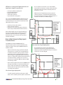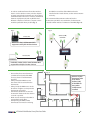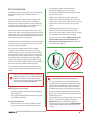
1
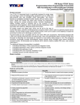
VST5000W5028W
Wireless Survey Tools
User Guide
August 30th, 2010
Product Overview
Index
Product Overview
2
The Vykon wireless survey tools are intended to verify
and validate the deployment and use of the Vykon
wireless thermostats on a potential job site.
Included in this package you will find the following items:
VYKONStat Wireless Network Overview
2
Basic Initial Design And
Deployment Consideration
3
Site Survey Overview
5
Knowing and understanding
the 6A / 5H rule of ZigBee
8
6A stands for 6 addresses maximum
per device / node / controller
8
Orphan Nodes
8
5H stands for 5 hops maximum
9
• 2 x Survey devices: SUR-A-5000 & SUR-B-5000
• 2 x 120 Vac charger for the tools
Before performing a survey, please insure that
both survey tools are fully charged overnight.
The survey tool will display a numerical percentage
value on the LCD screen which represents the wireless
network ZigBee RSSI dBi value (Receiving Signal Strength
Indicator).
Please note that it is normal for the value to
fluctuate slightly (up to 10-20%). The final
reading value is representative of the median
averaged values displayed.
• Any value from 10 to 100% indicates good
VYKONStat Wireless connectivity.
• Any value below 10% “may” indicate that
an extra Router VRP5000W1000W may need to
be installed.
VYKONStat Wireless Network Overview
Best practice VYKONStat Wireless initial
network start-up procedure
10
Disclaimer
11
VYKONStat Wirelessis a specification for a suite of high
level communication protocols using small, low-power
digital radios based on the IEEE 802.15.4-2003 standard
for wireless personal area networks (WPANs).
Mesh networking is a type of network where each node
in acts as an independent router. It allows for continuous
connections and reconfiguration around broken or
blocked paths by “hopping” and “re-meshing” from node
to node until the final destination is reached.
General characteristics of the wireless physical
communication layer are:
SUR-A-5000 & SUR-B-5000
VST5000W5028W Wireless Survey Tools User Guide
• Uses a wireless physical layer of 2.4GHz with a data
rates of 250 kbps
• Yields high throughput and low latency
• Automatic topology configuration: star,
peer-to-peer, mesh
• Handshake protocol for transfer reliability
• Range: 50 feet / 15M typical (up to 100 feet / 30 M
based on environment)
2
IEEE 802.15.4 along with ZigBee Networks and
Application Support Layer provide:
•
•
•
•
•
Low cost installation deployment
Ease of implementation
Reliable data transfer
Short range operation
Very low power consumption
the use of 802.15.4 channels 15, 25 and 26 ONLY.
802.11 Wi-Fi transmissions overlap and may interfere
with other channel selections allowed by 802.15.4
(Channels 11 to 24 ).
• With Clear line of sight deployment, (no physical
obstacles between 2 communicating thermostats)
the maximum distance between each thermostat is a
maximum of 100 feet or 30 Meters (fig. 1).
For a successful VYKONStat Wirelessdeployment, it is
important to understand that the wireless network
is influenced by the same environmental factors that
affect other wireless systems:
• Interference from radio emitters
• Various electronic devices
• Interference caused by solid objects that may
slow or stop communication between devices
Fig. 1
t
t
Even with potential sources of signal interference,
the presence of these factors should not result in
noticeable network performance degradation.
Environmental issues will occur with any wireless
network installation.
t
t
t
Basic Initial Design And Deployment
Considerations
The VYKON 2/6/7 JACE, VYKONStat Wireless
Communication option card, and installed wireless
software modules make up the VYKONStat Wireless
Gateway. (VWG).
• Vykon recommends using a per floor horizontal
architecture vs. a vertical one. Transmitting from
one floor to the other may be possible in certain
applications (such as going through stair ways),
but the design and optimization of the thermostat
antenna is designed for optimal horizontal distance
penetration and not a vertical one. As such, be
prepared to use AT LEAST ONE coordinator (VWG /
Jace-Driver) per floor.
t
t
G
t
• The maximum non-clear line of sight distance
between thermostats for gypsum wall partitions
which may include metal stud framing is a maximum
of 50 feet or 15 meters (fig. 2).
Fig. 2
t
t
t
Maximum
50 feet
(15 M)
between 2
thermostat
nodes
t
t
Clear line of sight deployment
VST5000W5028W Wireless Survey Tools User Guide
t
t
Non-clear line of sight deployment
• Please note that radio transmissions CANNOT travel
through steel. If floors are constructed with steel
joists or other steel materials it is highly unlikely
that the wireless thermostat transmissions will be
successful between floors.
• To avoid network interference with 802.11 Wi-Fi
devices in the 2.4GHz spectrum, Vykon recommends
Line of sight
distance
between 2
nodes is a
maximum
of 100 feet
(30 M)
t
t
t
t
t
t
G
t
3
• In order to avoid interference from other wireless
devices such as (wireless routers, wireless adapters
or laptop using wireless networks, etc.) insure that a
minimum distance of 3 feet or 1 meter is maintained
between any Vykon node and any Wi-Fi devices.
Maintain a distance of 10 feet or 3 meters or more
would be preferable when possible (fig. 3).
the VWG in a metal box. If the VWG needs to be
installed inside a metal cabinet, use the remote antenna
accessory.
The recommended maximum number of wireless
thermostats per JACE is 30; a minimum of 3 thermostats
should be within 50 feet or 15 Meters of the VWG (fig. 4 -5).
Fig. 4
Fig. 3
50 feet (15 M)
maximum
3 feet (1 M)
1
2
Minimum 3 feet (1 M) between Wi-Fi
equipment and Vykon wireless devices
10 feet (3 M)
Preferably 10 feet (3 M) or more between Wi-Fi
equipment and Vykon wireless devices
3
• Ensure that at least one thermostat
is within 50 feet (15 M) of the VWG
for every cluster of 10 thermostats
installed.
• Always install the VWG closest to
the center of all associated wireless
thermostats.
• Always locate the VWG near or in the
direct line of sight to as many wireless
thermostats as possible.
• Avoid metal, brick walls or concrete
obstructions between wireless devices
as much as possible.
• Make sure the antenna on the VWG is
perpendicular to the floor.
• Avoid placing the VWG and the
thermostats near metal or enclosing
Fig. 5
t
t
VST5000W5028W Wireless Survey Tools User Guide
At least 1 Vykon
thermostat node
to be within
50 feet (15M)
of the VWG for
every other
10 thermostat
installed.
t
t
t
t
t
t
t
G
t
4
Site Survey Overview
If available, it is best to have a floor plan layout showing
the location of all the proposed thermostats to be
installed.
If possible, perform the survey during occupied hours
where other electronic devices such as (computers,
wireless laptop, cell phones, PDA’s, wireless telephones,
microwave ovens, light ballasts, etc.) would be in use as
to generate as much interference as possible.
Some of these devices can generate interference up to
20 feet or 6.8 meters away during normal operation. Even
with possible sources of signal interference, the presence
of these wireless devices will most probably not result in
any network performance degradation.
It is important to understand that the survey values given
by the survey tool are provided as a worst case scenario
of a point to point application.
Once the whole is deployed with a Jace and VWG
coordinator and all wireless thermostats are present
and functioning as routers, the ability of the network to
efficiently route wireless signals cannot be compared to
this simple survey analysis method. Thus, it is important
to remember that the displayed percent signal ONLY
represents the signal strength from point A to point B.
As other devices join the network mesh, the route taken
from device A to device B will most likely change.
is designed for optimal horizontal distance
penetration. Holding the survey tool or the
thermostat horizontally will dramatically lower the
range of connectivity.
• Hold the survey tool at the location where you
would like to install the thermostat. The closer the
survey tool is to the actual installation location of the
thermostat, the more accurate the survey results
will be.
• Do NOT stand directly in between 2 survey tools
while measuring. Your body will interfere with
transmission signals. Always stand out of line of sight
to avoid interfering with the signal readings.
• To insure accurate readings, ALWAYS hold the tools
by the bottom using the battery holder (fig. 6).
Do not hold it by the thermostat case, as you may
cover the antenna (fig. 7).
Fig. 6
Fig. 7
A dense cluster of wireless thermostats will allow your
network to recover from temporary disturbances more
swiftly.
To ensure a proper survey, Vykon recommends
using ONLY channels 15 or 25 to avoid network
interference with 802.11 Wi-Fi devices in the
2.4GHz spectrum range. Begin by setting BOTH
devices to the SAME channel & PAN ID.
Before starting a site survey:
• Press the on button on both devices while holding
them side by side.
• 100% signal strength indicates that the survey tools
are functioning properly.
Survey Considerations:
• Always hold the survey device vertically to insure
proper measurements. The thermostats antenna
VST5000W5028W Wireless Survey Tools User Guide
Important Notes About The Survey Tools:
• The survey tools feature an auto-shutdown after
10 minutes. After 10 minutes, 10 quick audio beeps
will be heard; if the ON button is not re-pressed, the
unit after the count of 10 beeps, the unit will self
shutdown to prevent unnecessary battery drainage.
• The minimal expected battery life is at least 50 full
charge cycles. The maximum expected battery life is
200 full charge cycles.
• Contact Vykon for replacement batteries. The survey
tools use a custom rechargeable battery type.
DO NOT USE regular rechargeable batteries for
replacement; the charging circuit is NOT DESIGNED
for that. Doing so MAY result in critical failure and /
or injury.
5
Performing a site survey:
Let’s take this typical floor layout with the proposed thermostat & coordinator (VWG or Jace-Driver) (fig. 8).
Fig. 8
t
t
t
t t
t
t
t
t
c
Wireless Thermostat
t
t
t t
t t
t
t
t
t
t t
t
t
t
t
c
t
t
t
Proposed Wireless Coordinator VWG /Jace-Driver
1) Find the potential coverage radius of the coordinator
(VWG or Jace-Driver) at it’s proposed location. It’s
possible that another location may improve your
network performance or that you may require an
additional coordinator (VWG or Jace-Driver) or
additional REP5000W wireless repeaters.
2) Set one of the survey tools at the proposed
coordinator (VWG or Jace-Driver) and note down the
link quality of the signal strength for each proposed
thermostat location until you are out of range.
3) It is recommended that you test ALL thermostats to
properly insure coverage.
4) All thermostats within range of the coordinator
(VWG or Jace-Driver) can be expected to join the
network directly through the coordinator (VWG or
Jace-Driver) without any hops or routes (fig. 9).
Fig. 9
t
t
t
t t
t
Wireless Thermostat
24%
t
t
t
c
t
t
t t
t t
t
t
t
t
28%
t
t
65%
c
t
t
23%
t t
t
36%
58%
t
t
Proposed Wireless Coordinator VWG /Jace-Driver
VST5000W5028W Wireless Survey Tools User Guide
6
5) Then find the potential coverage radiuses through a few of the thermostats furthest away from the coordinator
(VWG or Jace-Driver) covered radius (fig. 10).
Fig. 10
t
t
t
t
t
41%
84%
t
t
t t
57%
t
43%
t
t
t
24%
t
t
t
23%
t t
65%
t
39%
33%
t
t
t
36%
c
Wireless Thermostat
63%
t
28%
t
t
c
t
36%
58%
t
t
Proposed Wireless Coordinator VWG /Jace-Driver
6) Once the most difficult connectivity scenarios have been tested and you are certain connectivity can be properly
established, planning the “potential” routes wireless transmissions will take on the network mesh can be a long
process. Keep in mind that the denser the thermostat clusters are, in terms of proximity and thermostat quantity,
the better your network efficiency will be (fig. 11).
Fig. 11
t
t
t
t t
t
Wireless Thermostat
t
t
t
t
c
t
t t
t t
t
t
t
t
t t
t
t
t
t
t
c
t
t
t
Proposed Wireless Coordinator VWG /Jace-Driver
VST5000W5028W Wireless Survey Tools User Guide
7
Knowing and understanding
the 6A / 5H rule of ZigBee
VYKONStat Wireless Networks are based on, a standard
which is suitable for wireless sensor and controller
networks. In ZigBee, a device / node / controller is said to
join a network if it can obtain a ZigBee network address
from a parent device. This ZigBee address is a value which
is NOT initially exposed or available for the integrator to
see.
Devices / nodes / controllers can calculate and assign
addresses for their surrounding devices by a distributed
address assignment scheme. This assignment is flexible,
but it does somewhat restricts the number of attached
devices and the possible depth of the said network for
any given device on the network.
ZigBee supports three kinds of networks type: star,
tree, and mesh networks. The ZigBee coordinator ( In
our case, this is the VWG ) is responsible for initializing,
maintaining, and controlling the network.
• A star network has a coordinator with devices
directly connecting to the coordinator.
• A tree and mesh networks, devices can communicate
with each other in a multi-hop fashion.
The network is formed by one ZigBee coordinator and
multiple ZigBee routers. A device can join a network as
an end device by the associating with the coordinator or
a router.
A ZigBee device / node / controller is said to have
successfully joined a network if it can obtain a ZigBee
network address from the main Jace coordinator or any
other router devices / nodes / controller.
6A stands for 6 addresses maximum
per device / node / controller
Any given device / node / controller including the
Jace –coordinator can ONLY give a maximum 6 ZigBee
addresses out to other devices so they join the active
ZigBee network. This means for any device / node
/ controller to be able to successfully join a ZigBee
network, it needs an address to be assigned by another
device / node / controller which is within connectivity
and that has NOT already assigned its maximum of 6
addresses allowed.
Please note that once a device / node / controller has
been assigned a ZigBee address & has joined the active
VST5000W5028W Wireless Survey Tools User Guide
ZigBee network, it will save its assigned ZigBee address
to flash memory & re-use it afterwards even after a power
failure or a network re-start. The ONLY time device / node
/ controller would require a NEW ZigBee address is if the
network is re-started with either a new PAN ID or a new
Channel value. This causes the currently assigned & saved
ZigBee address in flash to be erased & will force the /
node / controller to try to re-join a new network.
Orphan Nodes
It is important to understand that if a network is started
up incorrectly it “may” result in orphaned or unassigned
devices / nodes / controllers that will NOT join the ZigBee
network. Let’s first understand how an orphan node is
created. A typical example is when jobs are started on
a technician desk before sending the devices / nodes
/ controllers to the field for installation. Often the
integration technician will begin by powering up the
Jace – coordinator and connect it to the Workbench tool
creating and adding the Wireless Tstat Network driver
layer.
Once the Wireless Tstat Network driver layer is up and
running, the technician will then open and start up the
wireless devices / nodes / controllers one by one and add
them to their Niagara database.
• They will power the first unit, then add it to the
database and finally power it down.
• They will power up the second unit, add it to the
database and then power it down.
• This will be repeated to a maximum of 6 devices.
This will work fine for the first 6 devices only, simply
because the Jace – coordinator can provide a maximum
of 6 assignable addresses. When the technician powers
up the 7th device / node / controller, it will NOT be able
to join the ZigBee network unless one of the previous
device / node / controller is powered back on. Once this
is done, it will be able to assign the next 6 addresses as
usual.
In order to add another 6 devices, one of the previously
added device needs to be left on. If 42 devices are to
be added to the network, 8 of them should ALWAYS be
powered and be within connectivity range of all the
others.
How would orphan nodes appear in the field and how
would you allow them to join the ZigBee network ?
8
5H stands for 5 hops maximum
Please note that this ONLY applies to the initial network
start-up. Once all the devices are online to the Niagara
database, everything will operate seamlessly even on
power up / down & network re-starts.
ANY given device / node / controller should be
“optimized” to be NO FURTHER than 5 Hops to and from
the Jace / Coordinator. This is due to the nature of the
Vykon ZigBee stack in the wireless controllers.
How Orphan nodes are created in the field.
Ex.: 2 small buildings are within a few feet of each other.
Both have 6+ devices / nodes / controller each (fig.12).
Fig. 12
Building A
Jace
Jac
Building B
t t
t t
t t
t
Within Range
t t
t t
t t
t
1. Begin by positioning the Jace-coordinator centrally
in the floor space you are working in.
A possible cause for Building B orphan nodes is as follow:
Building A is first stated and sets the Jace – coordinator
configuration parameters for the PAN ID and Channel.
2. Find the coverage radius of the coordinator (VWG
or Jace-Driver) at its proposed location. It’s possible
that another location may improve your network
performance or that you may require an additional
coordinator ( VWG or Jace-Driver ) or additional
REP5000W wireless repeaters.
Premises:
• Building A is first stated.
• Yellow device / node / controller has given out its 6
addresses out to other devices in building A.
• Building B devices / nodes / controllers can only be
connected through blue device / nodes / controller
due to maximum distance coverage.
3. Set survey tool A at the proposed coordinator (VWG
or Jace-Driver)
Result:
4. With survey tool B, walk about the floor where a
cluster of controllers are to be found. Locate the
boundary where the signal strength is about 20%.
This represents the maximum radius of the first hop
where connectivity is possible based on the building
environment and partition construction.
Please note that this distance can be anywhere from
NIL to hundreds of feet (fig. 13).
• Because Blue controller cannot have an address
assigned by Yellow controller to join the network.
The all Orange devices / nodes / controllers cannot
join the ZigBee network either.
Getting orphan devices back on the network:
• Disconnect and bring one of the building B
device / node / controllers and power it up in
building A until it joins the ZigBee network
( confirmed either at the Jace – coordinator
or using the status LED on the wireless
communication card of the device / node /
controller).
• When the device / node / controller has joined
the network in building A and is added to the
Niagara database, bring it back into building
B so it can propagate ZigBee addresses to the
other devices in building B.
To properly layout the architecture and
determine the number of Jace’s required
on the job site, begin by establishing the
maximum possible coverage of a single
Jace with a wireless communication card
respecting the 5 hop maximum rule. This
can also done with the survey tools and
is covered in detail in the manual for the
survey procedures and tool usage: MAN
VWG-SURVEY-Exx.
Fig. 13
Proposed
location
Cluster of:
devices / nodes / controllers
B
20%
Jace
Coordinator
VST5000W5028W Wireless Survey Tools User Guide
A
Cluster of:
devices / nodes / controllers
9
Best practice VYKONStat Wireless initial
network start-up procedure
5. Leave survey tool B at this location and move survey
tool A towards the other clusters of controllers.
Locate the boundary where the signal strength is
about 20%. This represents the maximum radius
of the second hop where connectivity is possible
based on the building environment and partition
construction.
In order to avoid creating orphan devices / nodes
/ controllers and moving about devices / nodes /
controllers during the initial network start-up, it is
recommended that the same power up sequence initially
used for the survey be used.
6. Repeat the process until you establish the maximum
range covered by 5 hops where the last position
recorded represents the “safest” furthest position
that can be covered by a single Jace – coordinator
(fig. 14).
Please note that once a device / node / controller has
been assigned a ZigBee address and has joined the
active ZigBee network, it will save it’s assigned ZigBee
address to flash memory and re-use it afterwards even
after a power failure or a network re-start. The ONLY time
device / node / controller would require a NEW ZigBee
address is if the network is re-started with either a new
PAN ID or a new Channel value. This causes the currently
assigned and saved ZigBee address in flash to be erased
and will force the / node / controller to try to re-join a
7. If more than 5 devices / nodes / controllers are
present in the same area where readings were taken,
IT IS RECOMMENDED that another Jace coordinator
be used (fig. 15).
Fig. 14
Proposed
location
B
Jace
Coordinator
A
20%
20%
20%
A
B
20%
20%
B
A
Maximum linear distance covered by a single Jace-Coordinator
Fig. 15
Channel 25 Pan ID=10
Proposed
location
B
Jace
Coordinator
A
20%
20%
A
20%
B
20%
B
20%
A
Channel 25 Pan ID=20
Jace
Coordinator
A
20%
B
VST5000W5028W Wireless Survey Tools User Guide
20%
Proposed
location
B
20%
20%
A
20%
A
B
10
new network. I.E. this is ONLY applicable during the initial
network start-up.
Points to Remember:
• Always write your transmission results on a plan
when possible.
• Use REP5000W repeaters if remote devices are too
far to bridge or the signal is too weak.
• You can move the coordinator (VWG or Jace-Driver)
to a new location if it helps create better clusters of
thermostats.
• You “should” always plan for a floor by floor
horizontal architecture vs. a vertical one.
• Additional coordinator (VWG or Jace-Driver) can
be used when clusters become too far apart in an
installation.
• You can always call Vykon technical support for
recommendations if you have a floor plan layout
available for review.
1. First power up the orange devices / nodes /
controllers in sequence as showed and wait until
they are joined to the network or matched to
their offline created counterparts ( see the device
management section in this manual on how to
create offline devices / nodes / controllers & match
them to discovered devices ).
2. All the remaining yellow devices / nodes / controllers
can now all be powered up to also join the network.
3. This start-up sequencing allows for ALL devices to be
discovered without creating orphan nodes (fig. 16).
Fig. 16
Proposed
location
Jace
Coordinator
Power
#1
t
t
t
t
t
t
Power
#2
t
t
t
t t
t
t
t
Power
#3
t
t
t
t t
t
t
t
t
Power
#4
t t
t
t t t
t t
t
t
t
t
t
Power
#6
t
Power
#5
Disclaimer
NO WARRANTY. Vykon (herein after referred to as
“Vykon”) makes no warranty as to the accuracy of or
use of this technical documentation. Any use of the
technical documentation or the information contained
therein is solely at the risk of the user.
Documentation may include technical or other
inaccuracies or typographical errors. Vykon reserves
the right to make changes to this document without
prior notice, and the reader should in all cases consult
Vykon to determine whether any such changes have
been made. The information in this publication does
not represent a commitment on the part of Vykon.
Vykon shall not be liable for incidental or
consequential damages resulting from the furnishing,
performance, or use of this material.
Electronic controls are static sensitive devices.
Discharge yourself properly before manipulation and
installing the Vykon wireless gateway.
Vykon may not be held liable for continued reliable
or robust operation of any and all wireless based
devices. Although Vykon has taken many precautions
in assuring the robustness of the VT7000 series
VST5000W5028W Wireless Survey Tools User Guide
wireless thermostat product line and associated
network access point. Please note; future application
of additional wireless devices utilizing the same or
similar channels and / or frequencies may degrade
performance of overall system and / or reliability.
Non-approved modifications or changes made to
the Wireless Communication Card VWG or wireless
thermostats may void the FCC compliance of the
VWG and wireless thermostats.
THIS DEVICE COMPLIES WITH PART 15 OF THE FCC
RULES. OPERATION IS SUBJECT TO THE FOLLOWING
TWO CONDITIONS: (1) THIS DEVICE MAY NOT CAUSE
HARMFUL INTERFERENCE, AND (2) THIS DEVICE MUST
ACCEPT ANY INTERFERENCE RECEIVED, INCLUDING
INTERFERENCE THAT MAY CAUSE UNDESIRED
OPERATION.
NOTE: THE MANUFACTURER IS NOT RESPONSIBLE
FOR ANY RADIO OR TV INTERFERENCE CAUSED BY
UNAUTHORIZED MODIFICATIONS TO THIS EQUIPMENT.
SUCH MODIFICATIONS COULD VOID THE USER’S
AUTHORITY TO OPERATE THE EQUIPMENT.
11
3951 Westerre Parkway, Suite 350 I Richmond, VA 23233 I USA
Phone: ( 804) 747-4771 I Fax: (804) 747-5204
[email protected] I www.vykon.com
028-0318 -R0
VYKON