1
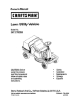
OWNER'S
MANUAL
MODELNO.
247.795940
I:RRFTSMRN®
Caution:
Readand Follow
All SafetyRules
andInstructions
BeforeOperating
This Equipment
5 HORSEPOWER
3 CUTTING STAGE
MULCHING AND BAGGING
CHIPPER-SHREDDER
Assembly
Operation
Customer Responsibilities
Service and Adjustment
Repair Parts
I
ii ii
SEARS,ROEBUCKAND CO., HoffmanEstates, IL 60179 U.S.A.
Printed in U.S.A.
770-8474H
3/93
SAFETY RULES
I_
WARNING:
TO REDUCE
SAFETY
INSTRUCTIONS,
PERSONAL
INJURY.
THE POTENTIAL
FOR ANY INJURY,
FAILURE
TO COMPLY
WITH THE
TRAINING
• Read this owner's manual carefully in its entirety before
attempting to assemble or operate this machine. Be completely familiar with the controls and the proper use of this
machine before operating it Keep this manuat in a safe
place for future and regular reference and for ordering
replacement parts.
• Children must never be allowed to operate this equipment.
• No one should operate this unit while intoxicated or while
taking medication that impairs the senses or reactions,
• This equipment should never be operated in the vicinity
of children, pets or other persons.
• Never run your machine in an enclosed area as the
exhaust from the engine contains carbon monoxide, which
is an odorless, tasteless and deadly poisonous gas.
• Never place your hands or any part of your body or clothing inside the feeding chamber, discharge chute, or near
any moving part while the machine or engine is running.
• If it is necessary for any reason to inspect or repair the
feeding chamber or any part of the machine where a moving part can come in contact with your body or clothing,
stop the machine, allow it to cool, disconnect the spark
plug wire from the spark p)ug and move it away from the
spark plug before attempting such inspection or repair.
PREPARATION
• Wear safety glasses provided with your unit while operating the chipper-shredder to prevent injury from any material which may be ejected out of the openings.
• Wear proper apparel. Avoid wearing loose fitting clothing.
Wear gloves when handling material.
• HANDLE GASOLINE WITH CARE as it is an extremely
flammable fuel.
• Check the fuel before starting the engine. Do not fill the
fuel tank indoors, while the engine is running, or while the
engine is still hot. Turn the unit off and let the engine cool
before refueling.
• Fuel your chipper-shredder
in a clean area. Do not
smoke while refueling.
• Fuel tank cap must be secure at alI times except during
refueling.
• Avoid spilling gasoiine or oil. Wipe the unit clean of any
spilled fuel or oil.
• Store fuel and oil in approved confiners,
away from heat
or open flame, and out of reach of children.
• This machine should be operated only upon a level surface.
• Assure that all screws, nuts and bolts and other fasteners
are properly secured.
OPERATION
• When feeding shreddable material into this equipment,
be extremely careful that pieces of metal, rocks, bottles,
cans or other foreign objects are not included. Personal
injury or damage to the machine could result.
COMPLY WITH
INSTRUCTIONS
THE FOLLOWING
MAY RESULT
IN
I
I
• If the cutting mechanism strikes any foreign object or if
your machine should start making an unusual noise or
vibration, immediately stop the engine, disconnect the
spark plug wire from the spark plug and move it away
from the spark plug. Allow the machine to stop and take
the following steps:
Inspect for damage.
Replace or repair any damaged parts.
Check for any loose parts and tighten to assure continued safe operation.
• The engine must be kept clean of debris and other accumulations.
• Do not allow an accumulation of processed material to
build up in the discharge area as this will prevent proper
discharge and can result in kick-back from feed opening.
• Never place your hands or any other part of your body or
clothing inside the feeding chamber, discharge chute or
near any moving part while the engine is running.
• Keep all guards and deflectors in place and in good working condition to assure continued safe operation.
• Always stand clear of the discharge area when operating
this machine.
• Keep your face and body back from the feed opening to
avoid accidental bounce back of any material.
• Do not ever-reach. Keep proper balance and footing at all
times.
• The engine governor settings on your machine must not
be altered, changed, or tampered with. The governor
controls the maximum safe operating speeds and protects the engine and all moving parts from damage
caused by overspeed.
• Do net transport machine while engine is running.
• Do not operate engine if air cleaner or cover directly over
carburetor air intake is removed, except for adjustment.
Removal of such parts could create a fire hazard.
MAINTENANCE AND STORAGE
• When this equipment is stopped for servicing, inspection,
storage or to change an accessory, make sure the spark
plug wire is disconnected from the spark plug and moved
away from the spark plug. The machine should be
allowed to cool down before making such inspection,
adjustments, service, etc. Maintain your machine with
care and keep it clean for the best and continued safe
operation.
• Do not use flammable solutions to clean the air filter.
• When not in use, your machine should be stored out of
the reach of children. Keep where gasoline fumes will not
reach an open flame or spark. For long periods of storage, refer to the "Storage" section of this manual.
LOOK FOR THIS SYMBOL TO POINT OUT
IMPORTANT SAFETY PRECAUTIONS. ITI
MEANS--ATTENTION!!! BECOME ALERT!!! I
YOUR SAFETY IS INVOLVED.
[
I
CONGRATULATIONS
PRODUCT SPECIFICATIONS
on your purchase of a Sears
Craftsman Chipper-Shredder. It has been designed, engineered and manufactured to give you the best possible
dependability and performance.
Should you experience any problem you cannot easily reinedy, please contact your nearest Sears Service Center/
Department in the United States. We have competent, welltrained technicians and the proper tools to service or repair
this unit.
Please read and retain this manual. The instructions will
enable you to assemble and maintain your chipper-shredder
properly. Always observe the "SAFETY RULES."
MODEL
NUMBER
Horsepower:
5.0
Displacement:
12.00 cu. in.
Fuel Capacity:
1-7/8 Quarts
(Unleaded)
Spark
Plug (Gap .030 in.):
Champion
J-SC (or
Equivalent)
247.795940
Ignition
Air Gap:
.0125 in.
SERIAL
NUMBER
DATE OF
PURCHASE
MAINTENANCE
AGREEMENT
THE MODELAND SERIAL NUMBERS WILL BE FOUND
ON A LABEL ATTACHED
TO THE FRAME OF THE
CHIPPER-SHREDDER.
A Sears Maintenance
Agreement
is available on this
product. Contact your nearest Sears store for details.
YOU SHOULD RECORD BOTH SERIAL NUMBER AND
DATE OF PURCHASE AND KEEP IN A SAFE PLACE
FOR FUTURE REFERENCE.
WARNING: This unit is equipped with an internal combustion engine and should not be used on or near any unimproved forest-covered, brush-covered or grass-covered land
unless the engine's exhaust system is equipped with a
spark arrester meeting applicable local or state laws (if any).
If a spark arrestor is used, il should be maintained in effective working order by the operator.
CUSTOMER
•
•
RESPONSIBILITIES
Read and observe the safety rules.
Follow a regular schedule in maintaining, caring for
and using your chipper-shredder,
Follow the instructions
under "Customer
Responsibilities"
and "Storage"
sections of this Owner's
Manual.
•
In the State of California the above is required by law
(Section 4442 of the California Public Resources Code).
Other states may have similar laws. Federal laws apply on
federal lands. A spark arrester for the muffler is available
through your nearest Sears Authorized Service Center (See
the REPAIR PARTS section of this manual.)
lUl
WARRANTY
ONEYEAR LIMITED WARRANTY ON CRAFTSMANGAS CHIPPER-SHREDDER
For one year from
the date of purchase,
tuned up according
to the instructions
material and workmanship.
If this Craftsman
Chipper-Shredder
when this Craftsman
in the owner's
manual,
is used for commercial
Chipper-Shredder
Sears
is maintained,
will repair,
or rental purposes,
free
of charge,
this warranty
lubricated
any
applies
and
defect
in
for only 30
days from the date of purchase.
This warranty does not cover:
•
•
Expendable items which become worn during normal use, such as blades, chipper blades,
spark plugs and catcher bags.
Repairs necessary because of operator abuse or negligence, including bent crankshafts
maintain the equipment according
to the instructions contained
in the owner's manual,
flails, air cleaners,
and the failure
to
WARRANTY
SERVICE IS AVAILABLE
BY RETURNING
THE CRAFTSMAN
CHIPPER-SHREDDER
TO THE
NEAREST
SEARS
SERVICE
CENTER/DEPARTMENT
IN THE UNITED
STATES.
THIS WARRANTY
APPLIES ONLY WHILE THIS PRODUCT
IS IN USE IN THE UNITED STATES.
This warranty
state.
gives you specific
legal rights, and you may also
have other rights which may vary from
SEARS, ROEBUCK AND CO., D/817WA, Hoffman Estates, IL 60179
state to
TABLE OF CONTENTS
SAFETY RULES .........................................................
2
PRODUCT SPECIFICATIONS ................................... 3
MAINTENANCE AGREEMENT .................................. 3
CUSTOMER RESPONSIBILITIES ............................. 3
WARRANTY ...............................................................
3
INDEX .........................................................................
4
ASSEMBLY ................................................................
5
OPERATION .........................................................
6-10
CUSTOMER RESPONSIBILITIES ..................... 10, 11
STORAGE ................................................................
12
SERVICE AND ADJUSTMENT ........................... 12-14
TROUBLE SHOOTING .............................................
15
PARTS ORDERING/SERVICE ................................. 15
REPAIR PARTS--CHIPPER-SHREDDER
........ 16, 17
REPAI R PARTS---ENGINE ................................. 17-20
iiiii
INDEX
i
A
................................................................
Accessories
4
Adjustments:
Carburetor .............................................................
14
Engine Speed .......................................................
14
Assembly Instructions:
Catcher Bag ............................................................
5
Chute Deflector .......................................................
5
C
Catcher Bag ................................................................
5
Controls ................................................
...................... 6
Customer Responsibilities .............................. 3, 10, 11
E
Engine:
Lubrication ............................................................
10
Maintenance ...................................................
10, 11
Starting ...................................................................
9
Stopping ..................................................................
7
Sto rage .................................................................
12
F
Fuel .............................................................................
8
L
Lubrication ................................................................
!0
M
Maintenance:
Agreement .............................................................
3
Schedule ...............................................................
10
Engine .............................................................
10, 11
Chipper-Shredder
................................................
10
O
Oil ...............................................................................
8
Operating Tips ........................................................
7, 8
R
Repair/Replacement Parts .................................. 16-20
Responsibilities, Customer ............................. 3, 10, 11
S
Safety Rules ...............................................................
2
Sharpening .........................................................
13, 14
Spark Plug ................................................................
1!
Specifications ..............................................................
3
Sto rage .....................................................................
12
T
Table of Contents .......................................................
4
Trouble Shooting ......................................................
15
U
Unclogging ................................................................
12
Unpacking ...................................................................
5
W
Warranty ....................................................................
3
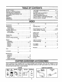
CHIPPER-SHREDDER
ACCESSORIES
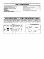
These accessories were available when the chipper-shredder was purchased. They are also available at most
Sears retail outlets, catalog and service centers. Most Sears stores can order repair parts for you, when you provide the model number of your chipper-shredder.
ENGINE
Spark I Air
Plug
Filter
Muffler
Engine
OII
CHIPPER-SHREDDER
Gas Can
Stabilizer
Vacuum
Hose Kit
Tow Hitch
Kit
iiii
ASSEMBLY
INSTRUCTIONS
IMPORTANT: This unit is shipped WITHOUT GASOLINE or OIL. After assembly, see operation section of
this manual for proper fuel and engine oil recommendations.
NOTE: To determine right and left hand sides of your
chipper-shredder, stand behind and face the hopper
(engine is at the front of the unit).
Your chipper-shredder
has been completely assembled at the factory, except for the chute deflector and
the catcher bag. A pair of safety glasses are atso
included in the carton.
TOREMOVE
CHIPPER-SHREDDER
FROMCARTON
Cut the corners of the carton. Remove all packing
inserts. Roll chipper-shredder out of the carton. Make
certain all parts, literature and the safety glasses have
been removed before the carton is discarded.
TOOLS REQUIRED FOR ASSEMBLY
(2) 7/16" or Adjustable Wrenches
HOWTO SET-UPYOUR CHIPPER-SHREDDER
MAKE CERTAIN
THE SPARK PLUG
WIRE IS DISCONNECTED AND MOVED
AWAY
FROM
THE SPARK
PLUG
BEFORE ASSEMBLING THE CHIPPERSHREDDER.
Chute
Deflector
Hex
Nut
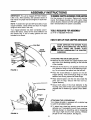
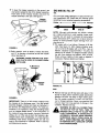
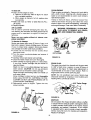
ATTACHING
THE CHUTE DEFLECTOR
•
Remove the hand knobs and cupped washers from
each side of the discharge opening on the left side
of the shredder.
•
Remove the hex lock nut, two spacers and hex bolt
from inside the hinge on top of the discharge opening. Do not remove one spacer from the hex bolt.
FIGURE 1.
• Place the chute deflector in position on the discharge opening. Insert bolt through hinge on chute
deflector and housing (spacer fits inside hinge).
Drawstring
•
Place second spacer over the he)( bolt, inside the
other part of hinge. Secure with hex lock nut.
Tighten securely.
•
Secure both sides of the chute deflector to the
housing using hand knobs and cupped washers
(cupped side of washers go against chute deflector).
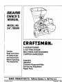
ATTACHING
THE CATCHER
BAG
Your chipper-shredder is equipped with a catcher bag
to catch the shredded material
FIGURE
2.
• To attach bag, place bag opening over the chute
deflector so it completely covers chute opening.
Depress plunger on drawstring, pull on drawstring
until bag is tight around chute opening. Release
plunger to lock it into position. See figure 2.
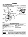
OPERATION
KNOW YOUR CHIPPER-SHREDDER
READ THIS OWNER'S MANUAL AND SAFETY RULES BEFORE OPERATING YOUR CHIPPER-SHREDDER.
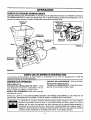
Compare the illustrations with your chipper-shredder to familiarize yourself with the location of various controls
and adjustments. Save this manual for future reference.
Hopper
Assembly
Oil Fill
Dipstick
Choke
Release
Chipper
Control
FIGURE 4.
Catcher
MEETS ANSI SAFETYSTANDARDS
Sears chipper-shredders conform to the safety standards of the American National Standards Institute.
OPERATINGCONTROLS(See
CHOKE
LEVER--Used
figures 3 and 4)
to enrich the fuel mixture in
the carburetor when starting a cold engine.
STARTER
engine.
HANDLE--Used
to manually start the
THROTTLE CONTROL--Controls
stops the engine.
RELEASE HANDLE--Used
when lowering to the ground.
BEFORE USING YOUR CHIPPER-SHREDDER,
AGAIN REFER TO THE "SAFETY
PAGE 2 OF THIS MANUAL. ALWAYS BE CAREFUL.
engine speed and
to release
the hopper
RULES" AS SHOWN ON
The operation of any chipper-shredder can result in foreign objects being thrown into
the eyes, which can result in severe eye damage. Always wear the safety glasses provided with the chipper-shredder or eye shields before chipping or shredding, or while
performing any adjustments or repairs. We recommend Wide Vision Safety Mask for
over spectacles or standard glasses available at Sears Retail or Catalog Stores.
TO STOP ENGINE
No Larger Than
Diameter
(Recommended)
Or 1" Diameter
(Maximum)
• Move throttle control lever to OFF position. See figure4.
• Disconnect spark plug wire and move away from
spark plug to prevent accidental starting while
equipment is unattended.
Assembly
HOW TO USE YOUR CHIPPER-SHREDDER
Do not attempt to shred or chip any material other
than vegetation found in a normal yard (i.e., branches,
leaves, twigs, etc.).
WARNING: THE CHIPPER-SHREDDER
DISCHARGES
MATERIALS WITH CONSIDERABLE
VELOCITY.
KEEP AWAY
FROM THE AREA AROUND THE CHUTE
DEFLECTOR.
ALWAYS
STOP
THE
ENGINE AND DISCONNECT THE SPARK
PLUG WIRE WHEN
REMOVING
OR
AI"I'ACHING THE BAG WHEN CHANGING
CONTAINERS OR WHEN REMOVING THE
SHREDDED MATERIAL. WEAR SAFETY
GLASSES
AND GLOVES WHENEVER
USING YOUR CHIPPER-SHREDDER.
The chipper-shredder
methods of operation.
&
t
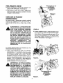
Leaves and small twigs can be raked into the hopper assembly when the hopper assembly is lowered to the ground. See figure 6. Small branches
up to 1/2" diameter (recommended) or 1" diameter (maximum) can also be fed into the hopper
assembly in this position. See figure 7.
is designed for three different
• Leaves and small branches up to 1/2" diameter
(recommended) or 1" diameter (maximum) can be
fed into the hopper assembly when it is in the
raised position. See figure 5. If it becomes necessary to push material into the chipper-shredder,
use a small diameter stick--NOT YOUR HANDS.
The stick should be small enough that it will be
ground up if gets into the impeller assembly.
WARNING:
FIGURE 5.
DO NOT
PUT
FIGURE 6.
MATERIAL
LARGER THAN 1/2" IN DIAMETER (RECOMMENDED)
or 1" DIAMETER (MAXIMUM) INTO THE HOPPER ASSEMBLY.
MATERIAL UP TO A MAXIMUM OF 3" IN
DIAMETER
MATERIAL
MAY BE FED
INTO THE CHIPPER CHUTE. DO NOT
ATTEMPT
TO SHRED OR CHIP ANY
MATERIAL LARGER THAN 3" IN DIAMETER. PERSONAL INJURY OR DAMAGE
TO THE MACHINE COULD RESULT.
o arger Than
112" Diameter
(Recommended)
Or 1" Diameter
(Maximum)
FIGURE 7.
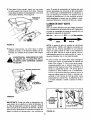
•
To lower the hopper assembly to the ground, use
one hand to grasp the top of the hopper assembly.
Push down on the release handle, and pivot the
hopper assembly to the right. See figure 8.
Hopper
Release
Handle
FIGURE 8.
• Bulky materiar, such as stalks or heavy branches,
up to 3" in diameter, should be fed into the chipper
chute. See figure 9.
WARNING: MAKE CERTAIN THE CHIPPER IN
NOT
CHUTE
USE. DOOR
IS CLOSED
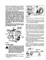
GASAND OIL FILL-UP
OIL
Only use high quality detergent oil rated with APt service crassification SG. Select the oil's viscosity grade
according to your expected operating temperature.
Colder <
32°F
-_ Warmer
5W30
SAE 30
NOTE: Although multi-viscosity oils (5W30, 10W30,
etc.) improve starting in cold weather, these multiviscosity oils will result in increased oil consumption
when used above 32°F. Check your oil level more frequently to avoid possible engine damage from running low on oil.
• Fill engine with oil as follows. Remove oil fill dipstick. See figure 10. With chipper-shredder
level,
use a funnel to fill engine with oil to FULL mark on
dipstick. Capacity is approximately 1-1/4 pints. Be
careful not to overfill. Tilt chipper-shredder toward
the left (from behind the hopper), then re-level.
Check oil level. Refill to FULL mark on dipstick if
necessary. Replace dipstick and tighten.
WHEN
3" Maximum
Diameter
•
,
i
f,
Oil
Dipstick
Drain
per
Chute
i
FIGURE 10.
GAS
FIGURE 9.
IMPORTANT:
There is a flail screen located inside
the housing in the discharge area. If the flail screen
becomes clogged, remove and clean as instructed in
the Service and Adjustments section. For best performance, it is important to keep the shredding blade
and the chipper blades sharp. If the composition of
the material being discharged changes (becomes
stringy, etc.) or if the rate at which the material is discharged slows down considerably, it is likely that the
shredding blade and/or chipper blades are dull and
need to be sharpened or replaced. Refer to Service
and Adjustments section.
• Remove fuel cap and fill fuel tank with about 1-7/8
quarts of clean, fresh, lead-free grade automotive
gasoline. DO NOT use Ethyl or high octane gasoline. Be certain container is clean and free from
rust or foreign particles. Never use gasoline that
may be stale from long periods of storage in the
container. Replace fuel cap.
1/2 INCH OF TOP OF FUEL TANK TO
WARNING:
DO NOTAND
FILLTO
CLOSER
PREVENT SPILLS
ALLOW THAN
FOR
FUEL EXPANSION.
IF GASOLINE
IS
ACClDENTLY SPILLED, MOVE CHIPPERSHREDDER
AWAY FROM AREA OF
SPILL. AVOID CREATING ANY SOURCE
OF IGNITION UNTIL GASOLINE VAPORS
HAVE DISAPPEARED.
Check the fuel level periodically to avoid running out
of gasoline while operating the chipper-shredder.
If
the unit runs out of gas as it is shredding or chipping,
it may be necessary to unclog the unit before it can be
restarted. Refer to "Removing the Flail Screen" in
SERVICE AND ADJUSTMENT section.
WARNING: EXPERIENCE INDICATES THAT ALCOHOL BLENDED FUELS (CALLED GASOHOL OR
USING ETHANOL OR METHANOL) CAN ATTRACT
MOISTURE WHICH LEADS TO SEPARATION AND
FORMATION
OF ACIDS DURING
STORAGE.
ACIDIC GAS CAN DAMAGE THE FUEL SYSTEM
OF AN ENGINE WHILE IN STORAGE. TO AVOID
ENGINE
PROBLEMS,
THE FUEL
SYSTEM
SHOULD BE EMPTIED OR TREATED WITH FUEL
STABILIZER
BEFORE STORAGE FOR 30 DAYS
OR LONGER. USE FRESH FUEL NEXT SEASON.
SEE "STORAGE"
SECTION FOR ADDITIONAL
INFORMATION.
NEVER USE ENGINE OR CARBURETOR CLEANER PRODUCTS IN THE FUEL TANK OR PERMANENT DAMAGE MAY OCCUR.
Spark Plug,
Wire and
Starter
Handle
Throttle Control
i
FIGURE 12.
• Move choke lever to CHOKE position (See figure
13.).
• Grasp starter handle (see figure 12) and pull rope
out slowly until engine reaches start of compression cycle (rope will pull slightly harder at this
point). Let the rope rewind slowly.
NOTE: A noise will be heard when finding the start of
the compression cycle. This noise is caused by the
flails and fingers which are part of the shredding mechanism falling into place, and should be expected. In
addition, the flails and fingers will be noisy after the
engine is started, until the impeller reaches full speed.
• Pull rope with a rapid, continuous, full arm stroke,
Keep a firm grip on start handle. Let rope rewind
slowly. Do not let starter handle snap back against
starter.
Fuel
Tank
FIGURE 11.
TO STARTENGINE
_
THAN THE OPERATOR
IS STANDING
WARNING:
BE SURE NO ONE OTHER
NEAR THE CHIPPER-SHREDDER
WHILE
STARTING
OR OPERATING.
DO NOT
OPERATE THIS CHIPPER-SHREDDER
UNLESS THE CHUTE DEFLECTOR HAS
BEEN PROPERLY INSTALLED
AND iS
SECURED WITH THE HAND KNOBS.
• Attach spark plug wire and rubber boot to spark
plug if necessary. See figure 11.
• Place the throttle control lever in FAST position.
See figure 12.
• Repeat preceding two instructions
until engine
fires. When engine starts, move choke lever on
engine halfway between CHOKE and RUN.
NOTE: If engine does not fire after three attempts,
move choke lever halfway between CHOKE and RUN
position and try again. See figure 13.
• Move throttle control to IDLE position for a few minutes warm-up. Move choke lever to RUN position
as engine warms up,
NOTE: In order to idle smoothly, a new engine may
require 3 to 5 minutes running above slow idle speed.
Idle speed has been adjusted to be correct after this
break-in period.
CHOKE_';_
Position
,,::'"
•.;:;"
FIGURE 13.
Choke Lever
J
OFF
•
TO STOPENGINE
• Move throttle control lever to OFF position. See figure 13.
Disconnect spark plug wire and move away from
spark plug to prevent accidental
starting while
equipment is unattended.
ilUll =1
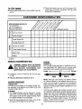
CUSTOMER
iii
iiii
MAINTENANCE
i
i
i
RESPONSIBILITIES
iiiiiiiiii
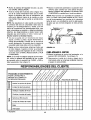
SCHEDULE
f_o_//_.3
AS YOU COMPLETE
/oe'_'-/_'//-
REGULAR SERVICE
/@_//"_"+'_'/'_/
_ "/^_/-°'_-/-_'_/
"_/
"-/_<_'/
....
SERVICE DATES
I--
o
0
Oil Pivot Points
t'
Clean Shredder
"J
-_
i.J
Check Engine Oil
_'
Change Engine Oil
u.I
4
_
._i
2:
Service Air Cleaner
Z
uJ
Clean Engine Cylinder
q
Spark Plug
_"
Muffler
_'
,t
CHECK
GENERALRECOMMENDATIONS
ENGINE
ENGINE OIL
Only use high quality detergent oil rated with API service classification SG. Select the oil's viscosity grade
according to your expected operating temperature.
Colder -=
32°F
_ Warmer
AND DISCONNECT
THE SPARK PLUG
WARNING:
ALWAYSPERFORMING
STOP THE ENGINE
WIRE
BEFORE
ANY
MAINTENANCE OR ADJUSTMENTS.
• Periodically
are tight.
check all fasteners
and be sure they
5W30
SAE 30
• Follow the Maintenance Schedule above.
NOTE: Although multi-viscosity oils (SE30, 10W30,
etc.) improve starting in cold weather, these multi- viscosity oils will result in increased oil consumption
when used above 32°F. Check your oil level more frequently to avoid possible engine damage from running low on oil.
CHIPPER-SHREDDER
LUBRICATION
Lubricate the pivot points on the release handle, hopper assembly, chute deflector and chipper chute once
a season using a light oil.
Your four-cycle engine will normally consume some
oil--therefore, check engine oil level regularly approximately every five hours of operation and before each
usage. Stop engine and wait several minutes before
checking oil level. With engine level, the oil must be to
FULL mark on dipstick (refer to figure 10). Change
engine oil after the first five hours of operation, and
every twenty-five hours thereafter.
CLEANING
• The chipper-shredder may be cleaned by running
water from a hose through the hopper assembly
and chipper chute with the engine running. Allow
the chipper-shredder to dry thoroughly.
• Wash the bag periodically with water. Allow to dry
thoroughly in the shade. Do not use heat.
10
To DrainOil:
CLEAN ENGINE
• Drain oil while engine is warm.
a. Remove oil drain cap. Refer to figure 10. Catch
oil in a suitable container.
b. When engine is drained of all oil, replace drain
cap securely.
• Refill with fresh oil. Refer to GAS AND OIL FILLUP section.
Clean engine periodically.
Remove dirt and debris
with a cloth or brush. Cleaning with a forceful spray of
water is not recommended as water could contaminate the fuel system.
Yearly or every 25 hours, whichever occurs first,
remove the blower housing and clean the areas
shown in figure 15 to avoid overspeeding, overheating
and engine damage. Clean more often if necessary.
• Replace dipstick.
AIR CLEANER
The air cleaner prevents damaging dirt, dust, etc.,
from entering the carburetor and being forced into the
engine and is important to engine life and performance.
Never run your engine without
pletely assembled.
air cleaner
FLER AREA TO REMOVE ALL GRASS,
WARNING:
PERIODICALLY DEBRIS,
CLEAN MUFDIRT AND COMBUSTIBLE
com-
To Service Air Cleaner:
Service pre-cleaner after every 25 hours of use, or at
least once a season. Service cartridge every 100 hours
of use, or at least once a season. Service pre-cteaner
and cartridge more often under dusty conditions.
• Loosen (do not remove) the two screws which
secure the cover.
• Turn the cover counterclockwise
and remove it
from the base.
• Carefully remove pre-cleaner and cartridge.
• Clean the inside of base and cover thoroughly.
• Clean cartridge by tapping gently on a flat surface.
If very dirty, replace cartridge and pre-cleaner or
clean as follows:
Levers
and Linkage
FIGURE 15.
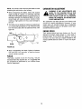
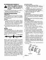
SPARK PLUG
The spark plug should be cleaned and the gap reset
to .030" at least once a season or every 50 hours of
operation. See figure 16. Spark plug replacement is
recommended at the start of each season. Refer to
engine parts list for correct spark plug type.
Wash in a low or non-sudsing detergent and warm
water solution. CAUTION: Do not use petroleum
solvents such as kerosene to clean cartridge.
Rinse thoroughly with flowing water from inside out
until water is clear.
NOTE: Do not sandblast spark plug. Spark plug
should be cleaned by scraping or wire brushing and
washing with a commercial solvent.
Allow cartridge to stand and air dry thoroughly
before using. DO NOT OIL CARTRIDGE OR PRECLEANER. DO NOT USE PRESSURIZED AIR TO
CLEAN OR DRY CARTRIDGE.
• Reassemble
cover to engine.
screws securely.
Tighten
Air
Intake
.030" Feeler Gauge
the two
Base
Filter
Pre-Cleaner
Spark Plug
FIGURE 16.
MUFFLER
Cover
Screws (2)
Do not operate the chipper-shredder without a muffler
or tamper with the exhaust system. Damaged mufflers
or spark attesters could create a fire hazard. Inspect
periodically, and replace if necessary. If your engine
is equipped with a spark arrester screen assembly,
remove every 50 hours for cleaning and inspection.
Replace if damaged.
Cover
FIGURE 14.
11
i
ii
i
i i
iii
ill
i
ii
i
STORAGE
Prepare your chipper-shredder for storage at the end
of the season or if the unit wilt not be used for 30 days
or more.
• Drain the fuel tank.
• Start the engine and let it run until the fuel lines and
carburetor are empty.
• Never use engine or carburetor c}eaner products in
the fuel tank or permanent damage may occur.
• Use fresh fuel next season.
WITH FUEL IN THE FUEL TANK INSIDE
WARNING:
STORE
MACHINE
OF BUILDINGNEVER
WHERE
FUMES
MAY
REACH AN OPEN FLAME OR SPARK, OR
WHERE
IGNITION
SOURCES
ARE
PRESENT SUCH AS HOT WATER AND
SPACE HEATERS, FURNACES, CLOTHES
DRYERS, STOVES, ELECTRIC MOTORS,
ETC.
NOTE: Fuel stabilizer is an acceptable alternative in
minimizing the formation of fuel gum deposits during
storage. Add stabilizer to gasoline in fuel tank or storage container. Always follow the mix ratio found on
stabilizer container. Run engine at least f0 minutes
after adding stabilizer to allow the stabilizer to reach
the carburetor. Do not drain the gas tank and carburetor if using fuel stabilizer.
• Drain all the oil from the crankcase (this should be
done after the engine has been operated and is stiff
warm) and refill the crankcase with fresh oil
NOTE: A yearly check-up by your local Sears Service
Center is a good way to make certain your chippershredder will provide maximum performance for the
next season.
CHIPPER-SHREDDER
•
Clean the chipper-shredder
• If you have drained the fuel tank, protect the inside
of the engine as follows. Remove spark plug, pour
approximately 1/2 ounce (approximately one tablespoon) of engine oil into cylinder and crank slowly
to distribute oil. Replace spark plug.
thoroughly.
• Wipe unit with an oiled rag to prevent rust (use a
light oil or silicone).
ENGINE
OTHER
IMPORTANT:
IT IS IMPORTANT
TO PREVENT
GUM DEPOSITS FROM FORMING IN ESSENTIAL
FUEL SYSTEM PARTS SUCH AS CARBURETOR,
FUEL FILTER, FUEL HOSE, OR TANK DURING
STORAGE. ALSO, EXPERIENCE INDICATES THAT
ALCOHOL BLENDED FUELS (CALLED GASOHOL
OR USING ETHANOL
OR METHANOL)
CAN
ATTRACT MOISTURE WHICH LEADS TO SEPARATION AND FORMATION OF ACIDS DURING STORAGE. ACIDIC GAS CAN DAMAGE THE FUEL SYSTEM OF AN ENGINE WHILE IN STORAGE.
• De not store gasoline from one season to another.
• Replace your gasoline can if your can starts to rust.
Rust and/or dirt in your gasoline will cause problems.
• Store unit in a clean, dry area. Do not store next to
corrosive materials, such as fertilizer.
NOTE: If storing in an unventilated or metal storage
shed, be certain to rustproof the equipment by coating
with a _ight oi! or silicone.
ii
i
•
SERVICE & ADJUSTMENT
i
&
i iiii
IIIII
IIII
II
WARNING: ALWAYS STOP ENGINE AND
DISCONNECT SPARK PLUG WIRE AND
MOVE IT AWAY FROM SPARK PLUG
BEFORE PERFORMING
ANY ADJUSTMENTS OR REPAIRS.
• Loosen the two hand knobs on each side of the
chute deflector. Lift the chute deflector up, and tie it
out of the way.
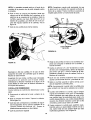
• Remove two hairpin clips from the clevis pins which
extend through the housing. Remove the clevis
pins. Lift the flail screen from inside the housing.
See figure 17.
REMOVINGTHE FLAIL SCREEN
If the discharge area becomes clogged, remove the
flail screen and clean area as follows.
• Clean the screen by scraping
water. Reinstall the screen.
• Stop the engine, make certain the chipper-shredder
has come to a complete stop and disconnect spark
plug wire from the spark plug before unclogging the
chute.
or washing
with
NOTE: Be certain to reassemble the flail screen with
the curved side down as shown in figure 17.
12
Chute
Replace or sharpen blades, Ff sharpening, make certain to remove an equal amount from each blade.
Reassemble in reverse order.
Hairpin
Clips,
Clevis
Pins
Make certain blades are reassembled with the sharp
edge facing the direction shown in figure 18 (sharp
edge is assembled toward the slotted opening in the
impeller assembly).
SHREDDING
_- Hex
Nuts
Washers
BLADE
The shredding blade may be removed for sharpening
or replacement as follows.
Flail
Screen
• Disconnect spark plug wire and move it away from
spark ptug.
• Lower the hopper assembly. Block up the housing.
See figure 19.
Chipper
Chute
• Remove the six hex lock nuts and lock washers
from the housing weld bolts using a 1/2" wrench.
Separate the chipper-shredder into two halves.
Hand Knobs
FIGURE 17.
SHARPENINGOR REPLACINGTHE BLADES
• Remove the back-up plate.
CHIPPER BLADES
NOTE: When reassembling, make certain the opening on the back-up plate is toward the bottom of the
unit. The back-up plate may be reversed to provide a
new cutting edge.
• Disconnect spark plug wire and move it away from
spark plug.
• Remove the flail screen as instructed
section.
in previous
• Remove the chipper chute by removing three hex
nuts and washers. A 1/2" wrench is required. See
figure 17.
Allen
Screws
NOTE: When reassembling, the cupped washer goes
on the bottom of the chipper chute with the cupped
side against the chute.
Pi
• Rotate the impeller assembly by hand until you
locate one of the chipper blades in the chipper
chute opening. Remove the blade, using a 3/16"
allen wrench on the outside of the blade and 1/2"
wrench on the impeller assembly (inside the housing). See figure 18.
• Remove the other blade in the same manner.
Torque
Wrench
FIGURE 19.
O
Loosen the two hand knobs and cupped washers
which secure the chute deflector, and raise the
chute deflector.
o
Insert a 1/2" or 3/4" diameter pipe through the flail
screen into the impeller to keep it from turning, or
remove the flail screen and insert a piece of wood
(2 x 4) into the chute opening.
Remove the two outside screws on the blade,
using a 3/16" allen wrench and a 112"wrench.
Remove the blade by removing the center bolt, lock
washer and flat washer.
FIGURE 18.
13
CARBURETORADJUSTMENT
NOTE: Use caution when removing the blade to avoid
contacting the weld bolts on the housing.
WARNING:
• When sharpening the blade, follow the original
angle of gdnd as a guide. It is extremely important
that each cutting edge receives an equal amount of
grinding to prevent an unbalanced blade. An unbalanced blade will cause excessive vibration when
,_
rotating at high speeds and may cause damage to
the unit.
IF ANY ADJUSTMENTS
ARE
MADE TO
ENGINE
THE
ENGINE
IS THE
RUNNING
(E.G.WHILE
CARBURETOR), KEEP CLEAR OF ALL MOVING
PARTS. BE CAREFUL OF HEATED SURFACES AND MUFFLER.
The carburetor has been pre-set at the factory and
should not require adjustment.
However, if your
engine does not operate properly due to suspected
carburetor problems, take your shredder to your nearest SEARS Service Center.
• The blade can be tested for balance by balancing it
on a round shaft screwdriver or nail. Remove metal
from the heavy side until it is balanced evenly. See
figure 20.
ENGINESPEED
Your engine speed has been factory set. Do not
attempt to increase engine speed or it may result in
personal injury. If you believe the engine is running
too fast or too slow, take your chipper-shredder to the
nearest SEARS Service Center for repair and adjustment.
/
o,!o2
FIGURE 20.
• When reassembling the blade, tighten to between
550 and 650 inch pounds,
or lacking torque
wrench, tighten securely.
FLAILS
The flails, located inside the housing,
may be
reversed when they become dull. _t is suggested that
this procedure be performed by your nearest Sears
Service Department.
14
i
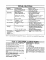
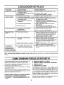
TROUBLE SHOOTING
PROBLEM
POSSIBLE CAUSE(S)
CORRECTIVE
Engine
• Fuel tank empty, or stale fuel.
• Spark plug wire disconnected.
• Faulty spark plug.
• Fill tank with clean, fresh fuel.
• Connect wire to spark plug.
• Clean, adjust gap or replace.
•
•
•
Spar_<plug wire loose.
Unit running on CHOKE.
Blocked fuel line or stale fuel.
•
Water or dirt in fueT system.
•
Carburetor out of adjustment.
•
Dirty air cleaner.
• Connect and tighten spark plug wire.
• Move choke lever to OFF position.
• Clean fuel line; fill tank with clean
fresh gasoline.
• Disconnect fuel line at carburetor to drain fuel
tank. Refill with fresh fuel,
• Adjust carburetor or contact your SEARS
Service Center.
• Service air cleaner. See Customer Responsibilities
section of this manual.
fails to start
Loss of power;
operation erratic
ACTION
Engine overheats
•
Carburetor not adjusted
properly.
• Engine oil level low.
•
Contact your SEARS Service Center.
•
Fill crankcase with proper oil.
Too much vibration
•
Loose parts or damaged
impeller.
• Stop engine immediately and disconnect
spark plug wire. Tighten all bolts and nuts.
Make all necessary repairs. If vibration continues,
have unit serviced by a SEARS Service Center.
Unit does not
discharge
•
Discharge chute clogged.
•
•
Foreign object lodged in impeller.
•
•
Shredding blade and/or chipper
blades dull.
•
Rate of discharge
slows considerably
composition
of
discharged
changes
or
Stop engine immediately and disconnect
spark plug wire. Clean flail screen and inside
of blower housing, See Service/Adjustments
section of this manual.
Stop engine immediately and disconnect
spark plucj wire. Remove lodged object,
Sharpen or replace shredding and chipper
blades.
material
NOTE: For repairs beyond the minor adjustments listed above, please contact your nearest SEARS Service Center.
HOW TO ORDER REPLACEMENT
PARTS
Each chipper-shredder
has its own model number.
Each engine has its own model number.
*ENGINE MODEL NO. - HSS0-67344G
The model number for your chipper-shredder
found on a label attached to the frame.
*PART DESCRIPTION
*PART NUMBER
will be
Your Sears merchandise has added value when you
consider that Sears has service units nationwide
staffed with Sears trained technicians...professional
technicians specifically trained on Sears products,
having the parts, tools and the equipment to insure
that we meet our pledge to you..."we service what we
sell."
The model number for the engine will be found on the
blower housing of the engine.
All parts listed herein may be ordered through Sears,
Roebuck and Co. Service Centers and most Retail
Stores.
WHEN ORDERING REPAIR PARTS, ALWAYS GIVE
THE FOLLOWING INFORMATION:
*PRODUCT-
"5 H.P. Chipper-Shredder"
*MODEL NUMBER - 247.795940
15
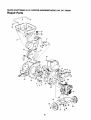
SEARS
CRAFTSMAN
Repair
5 H.P. CHIPPER-SHREDDER
MODEL
Parts
67
57
\
19
5O
69
_
6
!I
42
59
\
16
NO. 247.795940
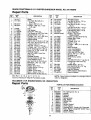
SEARS
CRAFTSMAN
5 H.P. CHIPPER-SHREDDER
MODEL
NO. 247.795940
Repair Parts
KEY
NO.
PART
NO.
1
2
742-0571
710-1254
736-0217
736-0247
6
7
8
9
10
11
12
13
14
15
16
17
18
19
20
21
22
23
24
25
26
27
28
29
30
31
32
33
34
35
11459B
711-0564
711-0833A
711-0834
715-0249
736-0192
681-0030
781-0490
710-1054
712-0411
736-0119
710-0825
736-0142
750-0793
711-0835
731-1427
712-0291
714-3010
781-0457
714-0149B
781-0480
712-3010
736-0242
720-0170
747-0744A
732-0542
781-0489
781-0475
736-0170
712-3010
KEY
NO.
DESCRIPTION
Blade
Hex Patch Bolt 3/8-24 x
2.25" Lg.
L-Wash. 3/8" I.D.H.D.
FFWash..406" I.D. x 1.25"
O.D. Hdn.
Flail
Fiail Spacer
Clevis Pin .496" Dia.
Flail Spacer w/.160" Dia. Hole
Spring Roll Pin 1.12" Lg,
FI-Wash..531" I.D. x .94" O.D.
Impeller Ass'y. Comp.t
Chipper Blade
Flat Hd. Scr. 5/16-24 x .75" Lg.
Hex Top L-Nut 5/16-24 (Gr. 5)
L-Wash. 5/16" I.D.*
Hex Bolt 1/4-20 x 3.75" Lg.*
FI-Wash..281" I.D. x .50" O.D.
Chute Hinge Spacer 1.66" Lg.
Clevis Pin .5" Dia. x 4.62" Lg.
Rotating Hopper
Hex Ctr. L-Nut 1/4-20 Thd.
Cotter Pin
Shredder Screen
Internal Cotter Pin 3/8" Dia.
Chute Deflector Ass'y.
Hex Nut 5/16-18 Thd. (Gr. 5)
Bell-Wash..345"
I.D. x .88"
Hand Knob
Chipper Door Rod
Torsion Spring 1.14" Lg.
Chipper Door
Chipper Chute Ass'y.
Spec. L-Wash. 5/16" I.D.
Hex Nut 5/16-18 Thd. (Gr. 5)
36
37
38
39
781-0510A
710-0157
736-0119
710-3008
40
41
42
43
44
710-0442
681-0004
781-0474A
735-0639
HS50-67344G
47
48
49
5O
53
54
55
56
57
58
59
61
62
63
64
65
66
712-0429
731-1428
781-0568
736-0264
732-0730
736-0117
749-0932
781-0574
781-0562
781-0561
726-0214
750-0786
738-0814
734-1600
720-0232
710-0376
710-1267
67
68
69
736-0451
710-0451
781-0515
764-0199A
723-0400
770-8474H
l"lncl. Ref. 1, 6, 7, 8, 9, 10, 11, 12, 13, 14
*Common Hardware--May
Be Purchased Locally.
TECUMSEH
5 H.P. ENGINE
MODEL
PART
NO.
DESCRIPTION
I
Shredder Frame
Hex Bolt 5/16-24 x .75" Lg.
L-Wash. 5/16" I.D.*
Hex Bolt 5/16-18 x .75" Lg.
(Gr. 5)
Hex Bolt 5/16-18 x 1.5" Lg.*
Flail Housing Ass'y.--L.H.
Flail Housing Ass'y.--R.H.
Spark Plug Boot
Engine_Tecumseh
HS50-67344G
Elastic Lock Nut 5/18-18 Thd.
Hopper Mtg. Collar
Locking Pin
FI-Wash. 5/16" I.D.
Spring 1.5" Lg.
FI-Wash..385"
I.D. x .62" O.D.
Handle
Back-Up Plate
Lower Locking Brkt.
Upper Locking Brkt.
Push Cap 5/8" Dia. Rod
Spacer .64" I.D. x .38" Lg.
Shredder Axle
Wheel Ass'y. Comp.
Knob
Hex Bolt 5/16-18 x 1" Lg. (Gr. 5)
Curved Carr. Bolt 5/16-18 x
1.25" Lg.
Saddle Wash, .32" I.D.
Carr. Bolt 5/16-18 x .75" Lg.
Front Support Brkt.
Bag (Not Shown)
Safety Glasses (Not Shown)
Owner's Manual
NOTE: Specifications
notice or obligation.
subject
to change
without
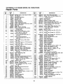
NO. HS50-67344G
Repair Parts
PARTS LIST FOR REWIND STARTER
KEY
NO.
1
2
3
4
5
6
7
8
9
10
11
12
13
-17
PART
NO.
590599A
590600
590615
590601
590598
590616
590617
590618
590619
590620
590687
590535
590452
590688
DESCRIPTION
Pin, Spring (Incl. No. 4)
Washer
Retainer
Washer
Spring, Brake
Dog, Starter
Spring, Dog
Pulley
Spring, Rewind
Cover, Spring
Housing Ass'y., Starter (400 Grommet)
Rope, Starter (Length 98" & 9/64" Dia.)
Handle, Starter
Starter, Rewind
TECUMSEH
5 H.P. ENGINE
MODEL
NO. HS50-67344G
Repair Parts
MODELandSERIAL
NUMBERSHERE
_261
380
243
18
TECUMSEH
5 H.R ENGINE
MODEL
NO. HS50-67344G
Repair Parts
KEY
NO.
PART
NO.
33674B
26727
34171
30969
28277
31334
31510
31335
650548
31426
32600
t33342
650561
75
8O
81
82
83
86
89
9O
92
93
100
101
DESCRIPTION
Cylinder Ass'y. (Incl. Nos, 2 & 20)
Pin, Dowel
Oil Drain Extension
OiPDrain Cap
Washer, Flat
Rod, Governor
Lever, Governor
Clamp, Governor Lever
Screw, Hex Washer Hd. 8-32 x 5/16
Spring, Extension
Seal, Oil
Baffle, Blower Housing
Screw, Hex Washer Hd. Durlok,
1/4-20 x 5/8
36421
Crankshaft Ass'y.
34535
Piston, Pin & Ring Ass'y. (Std.)
(Incl. Nos. 41,42 & 43)
34536
Piston, Pin & Ring Ass'y.
(.010 Oversize) (Incl. Nos. 41,
42 & 43)
34537
Piston, Pin & Ring Ass'y.
(.020 Oversize) (Incl. Nos. 41,
42 & 43)
33562B
Piston & Pin Ass'y. (Std.) (Incl.
No. 43)
33563B
Piston & Pin Ass'y. (.010 Oversize)
(Incl. No. 43)
33564B
Piston & Pin Ass'y. (.020 Oversize)
(Incl. No. 43)
33567
Ring Set, Piston (Std.)
33568
Ring Set, Piston (.010 Oversize)
33569
Ring Set, Piston (.020 Oversize)
20381
Ring, Piston Pin Retaining
32875
Rod Ass'y, Connecting (Incl. Nos.
46 & 49)
32610A
Bolt, Connecting Rod
27241
Lifter, Valve
32654
Dipper, Oil
33158
Camshaft (Compression Release)
29745
Extension, Blower Housing
30063
Screw, Torx T-30 Hex Washer. Hd.
Seres, 1/4-20 x 1/2
8345
Washer, Flat
650128
Screw, Hex Hd. Seres, 10-24 x 1/2
"27677A
Gasket, Cylinder Cover
34674C
Cover, Cylinder (Incl. Nos. 75, 80,
311 &312)
27897
Seal, Oil
30574A
Shaft, Mechanical Governor
30590A
Washer, Flat
30591, Gear, Governor (Incl. No. 81 )
30588AI Spool, Governor
650488
Screw, Hex Hd. Sems, 1/4-20 x 1-1/4
610961
Key, Flywheel
611080
Flywheel
650815, Washer, Bellevi!le
650816 I Nut, Flywheel
34443AJ Solid State Ass'y.
610118_ Cover, Spark Plug
KEY
NO.
102
103
110
118
119
120
!25
125
126
126
127
129
130
131
135
137
150
151
169
170
171
172
173
174
178
181
182
184
185
186
200
203
204
206
209
209A
215
223
224
238
239
242
243
245
246
250
260
261
267
268
274
275
19
PART
NO.
650872
650814
DESCRIPTION
Stud, Solid State Mounting
Screw, Torx T-15 Hex Washer Hd.
Sems, 10-24 x 1
Ground Wire
35182
35515
Rope Guard
"33554A
Gasket, Cylinder Head
33016A
Head, Cylinder (Incl. No. 131)
29313C
Valve, Exhaust (Std.) (Incl. No. 151)
29315C
Valve, Exhaust (1/32" Oversize)
(Incl. No. 151)
32644A
Valve, intake (Std.) (Incl. No. 151)
32645A
Valve, Intake (1/32" Oversize)
(Incl. No. 151)
650691
Washer, Flat
650818
Screw, Special Hex Hd., 5/16-18 x
1-1/2
6021A
Screw, Hex Flange Hd., 5/16-18 x
1-1/2
650694A
Screw, Hex Flange Hd., 5/16-18 x 2
33636
Resistor Spark Plug
29752
Nut & Lock Washer, 1/4-28
31672
Spring, Valve
31673
Cap, Valve Spring
"27234A
Gasket, Breather
27666
Body, Valve Cover
31410
Element, Breather
34146
Cover, Breather
353501 Tube, Breather
Screw, Hex Hd. Sems, 10-24 x 1/2
650128
29752
Nut & Lock Washer, 1/4-28
6201
Screw, Hex Hd., 1/4-28 x 7/8
650870 I Screw, Hex Hd., 1/4-28 x 1-11/16
"26756
Gasket, Carburetor
33666
Pipe. Intake
32698 i Link, Governor to ThrottLe
t33858A
Control Ass'y, Bracket (Incl. Nos. 203
& 204, 206, 209 & 209A)
31342
Spring, Compression
650549
Screw, Fil. Hd., 5-40 x 7/16
610973
Terminal Ass'y.
t650139
Screw, Fil. Hd Seres, 8-32 x 1/2
t30322
Lock Nut, Hex "Keps," 8-32
32410
Control Knob
30646
Screw, Fil. Hd. Sems, 1/4-20 x 1-3/8
"33673A
Gasket, Intake to Cylinder
650152
Screw, Fil. Hd., 8-32 x 3/8
"27272A
Gasket, Air Cfeaner
31914
Bracket, Air Cleaner
28820
Screw, Fil. Hd. Sems, 10-32 x 1/2
30727
Filter, Air Cleaner (Paper)
35974
Pro-Air Filter
Cover, Air Cleaner
31715
35657
Housing, Blower
29212
Screw, Hex Hd. Seres, 1/4-28 x 7/16
34212
Bracket, Hold Down
30200
Screw, Hex Washer Hd. Self-Tap
Seres, 10-24 x 9/16
"33670A
Gasket, Exhaust
35771
Muffler
TECUMSEH
5 H.P, ENGINE
MODEL
NO. HS50-67344G
Repair Parts
KEY
NO.
PART
NO.
277
285
287
650327
34694
650926
290
292
298
30962
26460
650665
3OO
35591
301
305
307
308
35355
35554
35499
35539
DESCRIPTION
KEY
NO,
Screw, Hex Hd., 1/4-20 x 2-3/8
Cup, Starter
Screw, Hex Washer Hd., 8-32 x
21/64"
Line, Fuel
Clamp, Fuel Line
Screw, Hex Washer Hd. Thread
Cutting, 1/4-15 x 7/8
Tank Ass'y., Fuel (Incl. Nos. 292 &
301)
Cap Ass'y., Fuel
Oil Fill Tube
"O'-Ring
Fill Tube Clip
310
313
327
340
342
35556
34080
35392
35230
650751
352
353
370
370A
380
390
400
420
35883
650926
36261
35344
631923
590688
33683B
730225
* Indicates Parts Included in Gasket Set, Ref. No. 400.
PART
NO.
DESCRIPTION
Dipstick
Spacer, Flywheel Key
Plug, Starter
Plate, Fuel Tank Mounting
Screw, Hex Washer Hd. Durlok,
1/4-20 x 7/16
Extension, Baffle
Screw, Hex Washer Hd., 8-32 x 21/64"
Decal, Instruction
Decal, Throttle
Carburetor (Incl. No. 184)
Starter, Rewind
Gasket Set (Incl Items Marked*)
Oil, 4-Cycle SAE 30 (Quart)
** In original production, the starter is riveted to the blower
housing. Replacement
housing has threaded studs.
Order four nuts (29752) when remounting starter.
1 In odginat production the speed control assembly is riveted to the blower housing baffle. Replacement speed control assembly includes screws and nuts for mounting.
Replacement baffle has threaded holes.
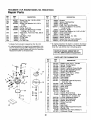
No. 35983
(Optional
Equipment)
I Part
MUFFLER
SPARK
ARRESTER
KIT
PARTS
KEY
14
4\
I
5
6
\
_16
24
2:3_o
31_®
30
--22
NO.
PART
NO.
1
2
3
4
5
6
7
8
9
10
11
12
631615
631767
631036
65O506
630766
650417
631919
630735
31837
*630748
*631027
*631021
13
14
15
16
631022
632019
*631024
631867
17
632042
18
631183
27110
*31839
21
22
_
23
24
25
26
27
29
3O
31
32
,
2O
*630740
*631078
*631028
631807
631184
631971
630738
630739
31840
631923
LIST FOR CARBURETOR
DESCRIPTION
Shaft & Lever Ass'y., Throttle
Spring, Throttle Return
Shutter, Throttle
Screw, Throttle & Choke Shutter
Spring, Idle Regulating Screw
Screw, Idle Regulating
Shaft & Lever Ass'y., Choke
Spring, Choke Stop
Shutter, Choke
Plug, Welch
Plug, Welch
Inlet Needle, Seat & Clip Ass'y.
(Incl. No. 13)
Clip, Inlet Needle
Float, Carburetor
Shaft, Float
Bowl, Float
Spring
Washer, Felt
Gasket, Bowl-to-Body
Adjustment Screw Ass'y, Main
(Incl. Nos. 21,23, 30 & 31)
O-Ring, Adjustment Screw
Screw, Idle Adjustment
Gasket, Bowl-to-Body
Fitting, Fuel Inlet
Washer
Seal, Dust
Spring, Main Adjustment Screw
Washer, Flat
Repair Kit (Incl. Items Marked *)
Carburetor Comp.
I
flANUALDEL
'ROPIETARIO
NUMERO DE
MODELO
247,795940
CRRFTSMRN
5 CABALLOS DE FUERZA
3 ETAPAS DE CORTE
CUBRIDOR DE PAJA Y EMBOLSADOR
PICADORA-DESMENUZADORA
Precaucibn:
Lea y observe
todas las reglas
e instrucciones
de seguridadantes Armado
de operar este
Operacibn
equipo
Responsabilidades del Cliente
Servicio y Ajuste
Piezas de Reparacibn
SEARS,ROEBUCK
ANDCO.,HoffmanEstates,IL 60195U.S.A.
preso en U.S,A.
770-8474H
3/93
REGLAS DE SEGURIDAD
IA
ADVERTENClA: PARA REDUClR EL POTENClAL DE CUALQUIER LESION CUMPLA CON LAS
INSTRUCClONES DE SEGURIDAD SIGUIENTES. LA FALLA EN CUMPLIR CON LAS INSTRUCCLONES PUEDE RESULTAR EN LESlONES PERSONALES.
ENTRENAMIENTO
• Lea este manual del propietario cuidadosamente por completo
antes de tratar de armar u operar
esta mdquina.
Est_
completamente familiarizado con los controles y el uso adecuado de esta m_.quina antes de operarla. Guarde este manual en
un lugar seguro para referencia futura y regular y pare ordenar
piezas de reemplazo.
• Nunca se debe permitir que los ni_:_s operen este equipo.
• Nadie deberfa operar esta unidad mientras est_ intoxicado o
estd tomando medicamentos
que menoscaban los sentidos o
reaccioees.
• Nunca deberfa operarse este equipo en la vecindad de niSos,
cachorros u otras personas.
• Nunca haga funcionar su m_quina en un &tea cerrada ya que el
escape del motor oontiene monbxido de carbono, el cual es un
gas inodoro, ins[pide y mortalmente venenoso.
• Nunca coloque sue manos o cualquier parle de su cuerpo o
ropas dentro de la cdmara de alimentaci6n, canaleta de descarga, o cerca de cualquier pieza m0vil mientras la m,_quina o
motor estd funcionando.
• Si por cualquier raz6n es neeesario inspeccionar o reparar la
c&mara de alimentaci6n o cualquier parle de la m_quina donde
una parte m6vil puede entrar en contacto con su cuerpo o ropes,
apague la m_quina, permita que se enfrie, desconecte el cable
de la Duj[a de la bujia y alejelo de la misma antes de intentar tat
inspecci6n o reparacibn.
PREPARACION
• Use los lentes de seguridad provistos con su unidad mientras
opere la picaciora.clesmenuzadora
para evitar lesiones por
cualquier mateda! que pueda ser sxpeiido pot las aberturas.
• Use ropas apropiadas. Evite user ropas suettas. Use guantes
cuando maneje el material.
• MANEJE CON CUIDADO LA GASOLINA ya que es un combustible extremadamente inflamable.
• Revise el combustible antes de encender el motor. No Ilene el
tanque de combustible bajo lecho, mientras el motor est_
funcionando, o mientras el motor est_ todavia caliente. Apague
la unidad y permita que el motor se enfrfe antes de cargar
combustible.
• Cargue combustible a su picadora-desmenuzadora
en un _rea
llmpia. No fume mientras carga combustible.
• La tapa ciel tanque de nafta debe ester asegurada en Iodo
momento excepto durante la carga de combustible.
• Evite derramar gasoline o aceite. Limpie la unidad de cualquier
combustible o aceite derramado.
• Almacene combustible y aceite en contenedores
aprobados,
lejos del calor o llamas, y fuera det alcance de los ni_os.
• Esta m_quina deberia operarse s61o at nivel de la superficie
• Aseg_3rese de que todos los lomillos, tuercas y pemos y otrcs
sujetadores est0n adecuadamente asegurades.
OPERACION
• Cuando alimente material desmenuzabte dentro de este equipo,
sea extremadamente
cuidacloso de que no incluya piezas de
metal, rocas, botellas, latas u otras olojetos extrafios. Podrla
resuttar en lesiones personates o cla_os a la m&quina.
&
•
•
•
•
•
•
•
•
•
•
I
Si el mecanismo de corte entra en eontacto con cualquier objeto
extraSo o si su mdquina comenzara a emitir un nJido inusual o
vibracibn, apague inmedialamente el motor, desconecte el cable
de la bujia y al_jelo de la misma. Permita que la m_,quina se
cletenga y efect_e las siguientes etapas:
Inspeccione pot da_o.
Reemplace o repare cualquier pieza decade.
Revise por piezas sueltas y ajuste pare asegurar una operaci6n
continuada segura.
Debe mantenerse
a la m=_quina libre de desechos
y otras
acumulacJones.
No permita que se acumule una acumulaci6n de material procesado en el ,_rea de descarga ya que esto evitart, la descarga
adecuada y puede resultar en una reacci6n de Is abertura de alimentacibn.
Nunca coloque sus manos o cualquier parte de su cuerpo o
ropas dentro de la cdmara de alimentaci6n, canaleta de descarga, o cerca de cualquier pieza mbvil mientras la m_quina o
motor estd funcionando.
Mantenga todas las guardas y deflectores en su lugar yen buenas condiciones de trabajo para asegurar una operaci6n continuada segura.
Cuando opere esta mdquina mant_ngase siempre alejado del
dree de descarga.
Mantenga
su cara y cuerpo detrds de la abertura
de alimentacibn pare evitar el rebote accidental de cua_quier material.
No se incline. Mantenga et equilibrio y posici6n de los pies
adecuadamente en to0o momento.
Los ajustes del regulador del motor en su m_quina no deben
alterarse, cambia_e,
o manipularse. E1 regulador controla las
velocidades m_ximas seguras y protege al motor y a todas las
piezas m_Sviles contra el daho causado por la sobrevelocidad.
No transporte la m_quina mientras el motor estd funcionando,
No opere el motor si se ha quitado el filtro de aire o la cubierta
directamente sobre la toma de aire del carburador, excepto para
ajustar. La extraccibn de tales piezas podria causer un riesgo de
ineendio.
MANTENIMIENTO
Y ALMACENAMIENTO
• Cuando este equipo se detiene pare servicio, inspecci6n,
almacenemiento o pare cambiar un accesorio, aseg6rese de
que el cable de la bujia est_ desconectado de la buj[a y atejado
de la misma. Se deberia permitir que la m&quina se enfrie antes
de efectuar tal inspeccibn, ajustes, servicio, etc. Mantenga su
m_quina con cuidado y mant_ngala limpia pars la operaci6n
mejor y rods continuada.
• No use soluciones inflamables pare limpiar el filtro de aire.
• Cuando no est_ en uSO, su mdquina deberia almacenarse fuera
del aloance de los niSos. Gu&rdela donde los vapores de la
gasolina no puedan alcanzar una llama o chispa. Refi_rase a la
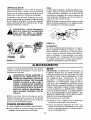
secci0n de =Almacenamiente" de este manual para periodos largos de almacenamiento,
iiiBUSQUE ESTE SIMBOLO PARA INDICAR
PRECAUCIONESIMPORTANTES DE SEGURIDAD. SIGNIFICA-ATENCION!]!
iiiESTE
ALERTA!liSU SEGURIDAD ESTA INVOLUCRADA.
FELICITACIONES
per su compra de una PicadoraDesmenuzadora Craftsman de Sears. Ha side dise_ada,
planeada y fabricada par proporcionarle la confiabilidad y
rendimiento mejor posible, Si tuviera alg0n problema que
no se pudiera remediar fdcilmente,
Ilame a su Centre/
Departamento
de Servicio
Sears mds cercano en los
Estados Unidos. Tenemos tecnicos competentes,
bien
entrenados y las herramientas
adecuadas para servir e
reparar esta unidad. Per favor lea y guarde este manual.
Las instrucciones le permitir&n armar y mantener su picadora-desmenuzadora
adecuadamente.
Siempre observe las
"REGLAS DE SEGURIDAD"
NUMERO DE
MODELO
ESPECIFICACIONES DEL PRODUCTO
Caballos de fuerza:
5.0
Desplazamiento:
12.00 pul.cub
Capacidad de combustible:
1-7/8 Cuartos
(Sin plomo)
Bujias (Distancia: .030 pul.):
Champion
J-8C (o
equivalente)
247.795940
Distancia de aire del encendido
NUMERO DE
SERIE
FECHA DE
COMPRA
ACUERDO
LOS NUMEROS
DE MODELO
Y SERIE SE HALLARAN EN UN ROTULO PEGADO AL MARCO DE
LA PICADORA-DESM
ENUZADORA
USTED DEBERIA REGISTRAR AMBOS, EL NUMERO
DE SERIE Y LA FECHA DE COMPRA Y GUARDAR EN
UN LUGAR SEGURO PARA REFERENClA FUTURA.
RESPONSABILIDADES
DEL CLIENTE
• Lea y observe las reglas de segurfdad.
• Siga un programa regular en mantener, cuidar y
usar su picadora-desmenuzadora.
• Siga las instrucciones
en las secciones
de
"Responsabilidades
del Cliente" y "Almacenamiento" de este Manual del Propietario.
.0125 pul.
DE MANTENIMIENTO
Un Acuerdo de Mantenimiento
de Sears estd
disponible para este producto. Llame a su tienda ma.s
cercana de Sears para detalles.
ADVERTENCIA: Esta unidad estd equipada con un motor
de combusti6n intema y no deberia usarse en o cema de
cualquier terreno cubierto per bosques no mejorados,
cubiertoper matorrales o grama a menos que el sistemade
escape del motor este equipado con un retenedor de chispas que cumpta con las leyes aplicables locales o del
Estado (de haberlas). Si se usa un retenedor de chispas,
deberfa mantenerse en una condici6n efectiva de trabajo
per el operador.
El Estado de California Io anterior se requiere per ley
(Seccion 4442 del C6digo de Recursos P_blicos de
California). Otros Estados pueden tener leyes simiiares.Las
leyes federales se aplican en los terrenos federales. Un
retenedor de chispas para el silenciador est,. disponible a
tray,s de su Centre de Servicio Autorizado de Sears (Yea
la secci6n de PIEZAS DE REPARACION de este manual.)
i
GARANTIA
iiiiiiiiii
ii
i
ii
UN ANO DE GARANTIA LIMITADA PARALA PICADORA-DESMENUZADORA A GASOLINA CRAFTSMAN
A partir de un a_o de la fecha de compra, cuando esta Picadora-Desmenuzadora
Craftsman sea mantenida,
lubricacla y puesta a punto de acuerdo con las instrucciones en el manual del propietario, Sears reparara.,
gratis, cualquier defecto en mater ales y confecc 6n
Siesta Picadora-Desmenuzadora
Craftsman se usa para fines comerciales o de alquiler, esta garant[a se aplica per sblo 30 dias desde la fecha de compra.
Esta garantia no cubre:
• Articulos descartables que se desgastan durante el use normal, tales come cuchillas, cuchillas picadoras,
desgranadoras, filtros de aire, bujias y bolsas colectoras.
• Reparaciones necesarias a causa de abuse o negligencia de! operador, incluyendo cig_ie_ales doblados y la
falla de mantener el equipo de acuerdo con tas instrucciones contenidas en el manual del propietado.
EL SERVICIO DE GARANTIA ESTA DISPONIBLE
RETORNANDO
LA PICADORA-DESMENUZADORA
CRAFTSMAN AL CENTRO/DEPARTAMENTO
DE SERVICIO MAS CERCANO DE SEARS EN LOS ESTADOS UNIDOS. ESTA GARANTIA SE APLICA SOLAMENTE MIENTRAS EL PRODUCTO ESTA EN use EN
LOS ESTADOS UNIDOS.
Esta garantia le proporciona derechos legales especificos,
pueden variar de Estado a Estado.
y usted puede tener tambien otros derechos que
SEARS, ROEBUCK AND CO., D/817WA, Hoffman Estates, IL 60195
TABLA DE MATERIAS
REGLAS DE SEGURIDAD .........................................
ESPEClFICAClONES DEL PRODUCTO ...................
ACUERDO DE MANTENIMIENTO .............................
RESPONABILIDADES DEL CLIENTE .......................
GARANTIA .................................................................
ACCESORIOS ............................................................
INSTRUCCIONES DE ARMADO ...............................
ACCESORIOS
2
3
3
3
3
4
5
OPERACION .........................................................
6-10
RESPONABILIDADES
DEL CLIENTE ................ 10-12
ALMACENAMIENTO .......................................... 12, 13
SERVICIO Y AJUSTE ......................................... 13-15
LOCALIZAClON DE FALLAS ................................... 16
COMO ORDENAR PIEZAS DE REPUESTO ........... 16
PARA LA PICADORA-DESMUNEZADORA
Estos accesorios estaban disponibles cuando se compro la picadora. Tambi_n estan a su disposici6n en la
mayoria de las tiendas al detalle y los centros de cat&logo y de servicio de Sears. La mayoria de las tiendas
Sears pueden hacer sus pedidos por piezas de repuesto, cuando usted les indique el n_mero del modelo de su
picadora-desmenuzadora.
MOTOR
Bujia
Filtro de
aire
Sllenclador
Acelte
para
motor
PICADORA-DESMENUZADORA
Recipiente para
gasollna
Establllzador
Kit Manguera
_
Aspirador
Kit
Remolcador
INSTRUCCIONES
IMPORTANTE: Esta unidad se envia SIN GASOLINA
O ACEITE. Despu_s del armado, vea la seccibn de
operaci6n de este manual para las recomendaciones
del combustible y aceite del motor adecuados.
NOTA: Para determinar los lados de mano derecha e
izquierda de su picadora-desmenuzadora,
parese
detr_.s y enfrente la tolva (et motor esta al frente de la
unidad),
Su picadora-desmenuzadora ha sido completamente
armada en la fabrica, excepto por deflector de la
canaleta y la bolsa colectora. Se incluyen tambien en
la caja los lentes de seguridad.
PARAEXTRAERLA PICADORA-DESMENUZADORA DE LA CAJA
Corte las esquinas de la caja. Extraiga todos las
inserciones de empaque. Ruede la picadora-desmenuzadora
fuera de la caja. Asegerese de que
todas las piezas y literatura se hayan sacado antes
de disponer de la caja.
HERRAMIENTASREQUERIDASPARAEL
ARMADO
(2) Llaves de 7/16" o ajustables
COMO PREPARARSU PICADORADESMENUZADORA
Separadores
ASEGURESE
int_
Deflector
de la tolva
hexagonal
Perilla de
FIGURA 1.
Cuerda
de extracci6n
FIGURA 2.
DE ARMADO
DE QUE EL CABLE DE LA
DO
DE ESTE
LA MISMA
ANTES DE ARMAR
LA
BUJIA
DESCONECTADO
Y ALEJAPICADORA-DESMENUZADORA
"<-SUJETANDO EL DEFLECTOR DE LA CANALETA
• Quite las perillas de mano y arandela acopadas de
cada 1ado de la abertura de descarga en el lado
izquierdo de la picadora-desmenuzadora.
• Quite la contratuerca hexagonal, dos separadores
y perno hexagonal de adentro de la bisagra en la
parte superior de la abertura de descarga. No
extraiga un separador del perno hexagonal.
• Coloque el deflector de la canaleta en posici6n en
la abertura de descarga. Inserte el perno hexagonal y separador en la bisagra en eI deflector y
cubierta de la canaleta (el separador calza dentro
de la bisagra). Vea la figura 1.
• Coloque el segundo separador sobre el perno
hexagonal, dentro de otra parte de la bisagra.
Asegure con la contratuerca hexagonal. Ajuste
firmemente.
• Asegure ambos lados del deflector de la canaleta a
la cubierta usando las peritlas de mano y arandelas
acopadas (el lado acopado de las arandelas esta
ubicado contraet deflector de la canateta).
SUJETANDO LA BOLSA COLECTORA
Su picadora-desmenuzadora estd equipada con una
bolsa colectora para colectar el matedal desmenuzado.
Para sujetar la bolsa, coloque la abertura de la
misma sobre el deflector de la canaleta de tal
manera de cubrir completamente la abertura de la
misma. Oprima el vastago sobre la cuerda de
extraccibn, y tire de la misma hasta que la bolsa
este ajustada
alrededor de la abertura de la
canaleta. Libere el vdstago para fijado en posici6n.
Vea la figura 2.
ii ii
i im
H
i
OPERAClON
i
j
CONOZCASU PICADORA-DESMENUZADORA
LEA ESTE MANUAL DEL PROPIETARIO Y I_AS REGLAS DE SEGURIDAD
ANTES DE OPERAR SU PICADO-
RA-DESMENUZADORA
Compare las ilustraciones con su picadora-desmenuzadora
ubicaci6n de varies controles y ajustes. Guarde este manual para referencia futura.
Conjunto de
ta tolva
para famifiarizarse
con la
Varilla para
medir la
profundidad
de Ilenado
de aceite
Palanca del
Palanca
de
Canaleta
de la
acelerador
FIGURA 4.
Bolsa
FIGURA 3.
'
CUMPLE CON LAS NORMAS DE SEGURIDADANSi
Las picadoras-desmenuzadoras
de Sears est_.n en conformidad
Institute Americano de Normas Nacionales.
con la norma de seguridad
B71.6-1982
dei
CONTROL DEL ACELERADOR - Controla la velocidad del motor y detiene el motor.
PALANCA DE DESENGANCHE - Usada para desenganchar la tolva cuando se baje at suelo.
CONTROLESDE OPERACION
(Vea la figura 3 y 4)
PALANCA DEL REGULADOR
DE AIRE - Usada
para enriquecer la mezcla de combustible en er carburador cuando se arranque un motor en frio.
MANIJA DEL ENCENDIDO-Usada
para encender
manualrnente el motor.
ANTES DE USAR SU PICADORA-DESMENUZADORA,
REFIERASE NUEVAMENTE A LAS "REGLAS
SEGURIDAD" INDICADAS EN LA PAGINA 2 DE ESTE MANUAL. SIEMPRE SEA CUIDADOSO.
DE
La operacion de cualquier picadora-desmenuzadora
puede resultar en que haya objetos
extraSos proyectados contra los ojos, Io que puede resultar en daSos graves a Jos ojos.
Siempre use los lentes de seguridad que estan provistos con la picadora-desmenuzadora
o
protectores de los ojos antes de picar o desmenuzar, o mientras efectuando cualquier ajuste o
reparacibn. Recomendamos la mascara de seguridad Wide Vision para usar sobre los anteojos
o lentes normales, disponible en las tiendas al per menor o de cat,_logo de Sears.
6
PARAAPAGAREL MOTOR
Mds pequefio que 1/2"
de didmetro
(Recomendado)
o 1" de di_imetro
(M=iximo)
• Mueva la palanca de control del acelerador a la
posici6n OFF (APAGADO). Vea la figura 4.
• Desconecte el cable de la bujfa y alejelo de la
misma para evitar un arranque accidental mientras
el equipo no est_ atendido.
Conjunto de
la tolva
COMO USAR SU PICADORADESMENUZADORA
No trate de picar o desmenuzar cualquier material
diferente
de vegetaci6n
que se encuentra
en
cualquier patio normal (por ej., rarnas, hojas, rarnitas,
etc.).
&
ADVERTENCIA:
LA PICADORA-DESMENUZADORA
DESCARGA
MATERIALES A UNA VELOCIDAD CONSIDERABLE. MANTENGASE
ALEJADO DEL
AREA ALREDEDOR
DEL DEFLECTOR
DE LA CANALETA. SIEMPRE APAGUE
EL MOTOR Y DESCONECTE EL CABLE
DE LA BUJIA CUANDO ESTE EN PROCESO DE SACAR
O SUJETAR
LA
BOLSA CUANDO CAMBIE LOS CONTENEDORES O CUANDO EXTRAIGA EL
MATERIAL
DESMENUZADO.
USE
LENTES DE SEGURIDAD
Y GUANTES
SIEMPRE QUE USE SU PICADORA-DESMENUZADORA.
FIGURA 5.
• Pueden rastrillarse hojas y ramitas peque_as cuando el conjunto de la tolva se baja al nivel del suelo.
Yea la figura 6. Ramas pequeSas de hasta 1/2" de
diametro (recomendado) o de 1" de diametm (maximo) pueden tambien alimentarse al conjunto de la
tolva en esta posicibn. Vea la figura 7.
La picadora-desmenuzadora
esta diseSada para tres
metodos diferentes de operaci6n.
• Hojas y rarnas pequeSas de hasta 1/2" de diametro
(recomendado) o 1" de didmetro (mdximo) pueden
alimentarse en el conjunto de la tolva cuando est_
en la posici6n elevada. Vea la figura 5, Si fuera
necesario
empujar
el material
dentro de la
picadora-desmenuzadora
use un palo de diarnetro
pequeSo - NO SUS MANOS. El palo debeda ser
suficientemente
pequeSo para ser molido si
quedara atrapado en el conjunto propulsor.
&
ADVERTENCIA:
NO PONGA MATERIAL
MAS GRANDE QUE 112" DE DIAMETRO
(RECOMENDADO)
O 1" DE DIAMETRO
(MAXlMO) DENTRO DEL CONJUNTO DE
LA TOLVA, PUEDE ALIMENTARSE A LA
CANALETA DE PICADO CON MATERIALES DE HASTA UN MAXIMO DE 3" DE
DIAMETRO.
NO TRATE DE PICAR O
DESMENUZAR
CUALQUIER MATERIAL
MAS GRANDE QUE 3" DE DIAMETROo
PODRIA RESULTAR EN LESlONES PERSONALES O DAI_IOS A LA MAQUINA.
FIGURA 6.
Mds pequefio que 1/2"
de di&metro
(Recomendado)
o 1" de didmetro
(Mdximo)
FIGURA
7.
picar. Si cambia la composicibn del material que est,_
siendo descargado (se convierte en tipo encordado,
etc.) o disminuye considerablemente la velocidad a la
cua! se descarga e! material, es posible que la
cuchilta de desmenuzar y/o las cuchillas de picar
est_n desafiladas y tengan que ser afiladas o reemplazadas. Refi_rase a [a seccidn de Servicio y Ajuste.
• Para bajar la tolva alsuelo, agarre con una mano
la parte superior del conjunto de la tolva. Presione
hacia abajo la palanca de desenganche, y tire de la
tolva hacia la derecha. Vea Ja figura 8.
Conjunto de
LLENADODE GAS Y ACEITE
ACEITE
$61o use aceite detergente de alta calidad clasificado
con la clasificaciSn de servicio SG de API. Seleccione
el grado de viscosidad del aceite de acuerdo con su
temperatura esperada de operaci6n.
Mds frio
_
32QF _
5W30
RGURA 8.
ADVERTENCIA:
ASEGURESE DE QUE
LA PUERTA DE LA CANALETA DE LA
PICADORA ESTE CERRADA CUANDO
NO SE USA.
Oiametro
rndximo
SAE 30
NOTA: A pesar de que los aceites de viscosidad
m01tiple (5W30, 10W30, etc) mejoran el arranque en
tiempo fr(o, _os mismos resultar&n en un consumo
mayor de aceite cuando se usen a una temperatura
mayor de 32_F. Revise su nivel de aceite mas frecuentemente
para evitar daho posible al motor a
causa de funcionar con un nivel bajo de aceite.
• Material voluminosos,
tal como ta[los o ramas
pesadas de hasta 3" de di&metro deberia ser alimentado a la canaleta de la picadora. Vea la figura
9.
&
Mds caliente
Llene elmotor con aceite como sigue. Extraiga ]a
varitla para medir la profundidad de Ilenado de
aceite. Vea la figura 10. Con el nivel de la picadora-desmenuzadora use un embudo para Ilenar de
aceite el motor hasta la marca FULL (LLENO) en la
varilla. La capacidad es de 1-1/4 pintas aproximadamente.
Sea cuidadoso de no sobrellenar.
Incline la picadora-desmenuzadora
hacia la
izquierda (desde atr&s de la tolva), y cotoque nuevamente a nivel. Revise el nivel de aceite. Llene
nuevamente a la marca FULL (LLENO) de la varilta si fuera necesario. Vuelva a colocar la varilla y
ajuste.
de 3"
;analeta
de la picadora
FIGURA 9.
para medir
la profundldad
de Ilenado
de aceite
IMPORTANTE: Existe una criba de desgranado ubicada dentin de la cubierta en el area de descarga. Si
la criba de desgranado se tapona, sdquela y limpie(a
como se instruye en la SecciSn de Servicio y Ajustes.
Para el mejor rendimiento es importante mantener aftladas la cuchiila de desmenuzar y las cuchillas de
Drenah
F|GURA 10.
8
GAS
Varilla para medir
la profundidad
de Ilenado de aceite
• Quite la tapa de combustible y Ilene el tanque con
aproximadamente
1-7/8 cuartos de gasolina de
autom6vil, limpia, fresca, sin plomo, de alto grado.
NO USE Etilo o gasolina de alto octano. Asegt_rese
de que el contenedor este limpid y libre de 6xido o
particulas extra,as. Nunca use gasolina que est_
rancia por haberse almacenado pot un periodo
largo en el contenedor. Vuelva a colocar la tapa de
combustible.
&
Bujia,
y funds
ADVERTENCIA: NO LLENE POR ENCIMA
DE 1/2 PULGADA DE DISTANCIA DE LA
PARTE SUPERIOR
DEL TANQUE
DE
COMBUSTIBLE
PARA EVITAR DERRAMES Y PARA PERMITIR LA EXPANSION DEL COMBUSTIBLE.
Sl SE DERRAMA GASOLINA ACClDENTALMENTE,
RETIRE LA PICADORA-DESNMENUZADORA DEL LUGAR
DEL DERRAME.
EVITE CREAR CUALQUIER FUENTE DE
ENCENDIDO HASTA QUE HAYAN DESAPARECIDO
LOS VAPORES
DE LA
GASOLINA,
e de
combustible
FIGURA 11.
PARAENCENDEREL MOTOR
Revise peri6dicamente el nivel para evitar quedarse
sin gasolina cuando este operando la picadora-desmenuzadora. Si la unidad se queda sin gas mientras
est& desmenuzando o picando, puede ser necesario
desatancar la unidad antes de que pueda encenderse
nuevamente. Refi_rase a "Extraccion del Tamiz de
Desgranar"
EN LA SECCION
DE SERVICIO
Y
AJUSTE.
_
ADVERTENCIA:
LA EXPERIENCIA
INDICA QUE
LOS COMBUSTIBLES
MEZCLADOS CON ALCOHOL (LLAMADO GASOHOL O USANDO ETANOL
O METANOL) PUEDE ATRAER HUMEDAD LO QUE
CONDUCE A LA SEPARACION Y FORMAClON DE
ACIDOS DURANTE EL ALMACENAMIENTO.
EL
GAS ACIDOGENO PUEDE DAI_AR EL SISTEMA
DE COMBUSTIBLE
DE UN MOTOR MIENTRAS
ESTA EN ALMACENAMIENTO.
PARA EVITAR
PROBLEMAS DEL MOTOR, EL SISTEMA DE COMBUSTIBLE DEBE VAClARSE O TRATARSE CON
UN ESTABILIZADOR DE COMBUSTIBLE
POR 30
DIAS O MAS ANTES DE ALMACENAR. LA PROXIMA TEMPORADA USE COMBUSTIBLE
FRESCO.
VEA LA SECCION
DE "ALMACENAMIENTO"
PARA INFORMAClON ADICIONAL.
NADIE MAS QUE EL OPERADOR ESTE
ADVERTENCIA:
DE QUE
PARADO CERCA ASEGURESE
DE LA PICADORA-DESMENUZAOORA
MIENTRAS
SE ESTE
ENCENDIENDO
U OPERANDO.
NO
OPERE ESTA PICADORA-DESMENUZADORA A MENDS QUE EL DEFLECTOR
DE LA CANALETA HAYA SlDO INSTALADO ADECUADAMENTE
Y ESTE ASEGURADO CON LAS PERILLAS DE MANO.
• Si fuera necesario una el cable de la bujfa y la
funda de goma a la bujfa. Vea la figura 11.
• Co!oque ta palanca de control del acelerador en la
posici6n FAST (LEGERO). Yea la figura 12.
Regulador de aire
NUNCA USE PRODUCTOS
DE LIMPIEZA
DE
MOTOR O CARBURADOR
EN EL TANQUE DE
COMBUSTIBLE
O PUEDE OCURRIR DAi_iO PERMANENTE.
FIGURA 12.
9
Control del acelerador
• Mueva la palanca del regulador de aire a /a posiciSn CHOKE (REGULADOR).
• Mueva el control del acelerador a la posicion IDLE
(VACIO) para calentar por unos pocos minutos.
Mueva la palanca del regulador a la posici6n RUN
(FUNClONAR) a medida que el motor se calienta.
• Tome la manija del encendido (yea la figura 14) y
tire de fa cuerda lentamente hasta que el motor
llegue al comienzo del ciclo de compresi6n (en
este punto debera tirarse de la cuerda un poco
m_.s fuerte). Deje que ta cuerda se enrolle lentamente.
NOTA" Para funcionar con suavidad en la posici6n de
vacfo, un motor nuevo puede requerir de 3 a 5 minutos de funcionamiento
por encima de la velocidad
lenta de vacfo. La vetocidad de vacfo ha sido ajustada para que sea correcta despues de este periodo
inicial.
NOTA: Se escuchar_ un ruido cuando se encuentre
el comienzo del ciclo de compresi6n. Este ruido es
causado por las desgranadoras
y dedos, que son
parte del mecanismo
de desmenuzamiento,
que
est_,n colocandose en posicion, y debeda anticiparse.
Adem,is, las desgranadoras
y dedos hardn ruido
despues que se encienda el motor, hasta que el
Posicibn_;;:."
de regulador ,,:,"
//
Nivel de
'q:'".,;o"
_lador
"""
Posici_n
tpagado
irnpulsor a]cance ]a velocidad m_xirna.
• Tire de la cuerda cot} un movimiento del brazo
ra.pido, continuo y pteno, Sujete firmemente
la
manija de encendido. Permita que la cuerda se
enrolle lentamente. No permita que la manija de
encendido salte hacia atras contra el encendido.
• Repita )as dos instrucciones anteriores hasta que
e_ motor dispare. Cuando el motor se enciende,
mueva la palanca del regulador de aire a mitad de
recorrido entre CHOKE (REGULADOR)
y RUN
(FUNCIONAR).
NO"I'A: Si el motor no dispara despues de tres intentos, mueva la patanca del regulador de aire a mitad
de recorrido entre la posicion de CHOKE y RUN y
trate nuevamente. Vea la figura 14.
i
n
FIGURA 13.
PARAAPAGAREL MOTOR
• Mueva la palanca de control del aceterador
posici6n OFF (APAGADO). Vea la figura 13.
• Desconecte el cable de la bujia y alejelo de la
misma para evitar un arranque a0ciclental mientras
el equipo no este atendido.
in
I
RESPONSABILIDADES
DEL CLIENTE
I
PROGRAMA DE MANTENIMIENTO
ANOTE LAS FECHAS A
MEDIDA QUE COMPLETA
EL SERVICIO REGULAR
.._'_,/.._/
_
II
I
A++//'
×++/
/
/ ++-/+.+-,
_" ___--/ .__ /
_'_
_,_/£4
/
Aceitar los puntos de pivote
_/
Limpiar la desmenuzadora
V
_
unn
Verificar el aceite del motor
Cambiar el aceite del motor
,J
",]
_/
,,.
,,
Servicio a[ filtro de aire
-V
Limpiar el cilindro del motor
_
o
Buj{a
Silenciador
_/ REVISAR
a la
10
_/
Para drenar el aceite:
•Drene
mientras el motor esta caliente.
a. Quite el tap6n de drenaje de aceite. Refi_rase a
la figura 10. Recoja el aceite en un contenedor
apropiado.
b. Cuando se haya drenado et aceite del motor,
reemplace seguramente et tap6n de drenaje.
• Vuelva a Ilenar con aceite fresco. Refierase a la
seccion de LLENADO DE GAS Y ACEITE.
• Vuelva a colocar la varilla.
RECOMENDACIONESGENERALES
MOTOR Y DESCONECTE EL CABLE DE
ADVERTENCIA:
SIEMPRE
LA BUJIA
ANTES
DE APAGUE
EFECTUAREL
CUALQUIER
MANTENIMIENTO
O
AJUSTES.
,_
• Revise periodicamente
todos los remaches
asegL_rese de que est_n bien ajustados,
• Siga el programa de Mantenimiento de arriba.
y
PICADORA-DESMENUZADORA
FILTRO DE AIRE
El filtro de aire evita que suciedad, polvo, etc. dafiinos
penetren en el carburador y sean forzados dentro del
motor y es importante para la duracion y rendimiento
del motor.
LUBRICACION
Lubrique los puntos de pivote de la barra de desenganche, conjunto de la tolva, deflector de la canaleta
y canaleta de la picadora una vez por temporada
usando aceite liviano.
Nunca haga funcionar sin el filtro de aire completamente armado.
Para servir el filtro de sire:
Sirva el prefiltro despues de cada 25 horas de uso, o
pot !o menos una vez por temporada. Sirra el cartucho cada 100 horas de uso, o por Io menos una vez
por temporada. Sirva el prefiltro y el cartucho mas a
menudo bajo condiciones de polvo.
• Aflojar (no soltar) los dos tomillos de ta cubierta.
MMPIEZA
• La picadora-desmenuzadora
puede limpiarse
haciendo correr agua de una manguera a traves
del conjunto de la tolva y canaleta de la picadora
con el motor funcionando. Permita que la picadoradesmenuzadora se seque completamente.
•
Lave peri6dicamente la bolsa con agua. Permita
que se seque completamente a la sombra. No use
calor.
• Gire la cubierta en sentido contrario a tas agujas
dez reloj y separe esta de ta base.
MOTOR
ACEITE DEE MOTOR
• Extralga con precauci6n el prefiltro y el cartucho.
$61o use aceite detergente de alta calidad clasificado
con la clasificaci6n de servicio SG de AP!. Seleccione
• Limpie el intedor de la base y la cubierta a fondo.
• Limpie el cartucho, sacudiendlo suavemente sobre
una superficie plana. Si esta muy sucio sustituya el
cartucho y el prefiltro o limpie los de la manera
siguiente:
el grado de viscosidad del aceite de acuerdo con su
temperatura esperada de operaci6n.
Mas frio
-._
32-°F -_--'-_Mas
5W30
caliente
Lavelo en un detergente no espunoso yen agua
templada.
Precaucion:
No use solventes
de
petroleo como el keroseno para limpiar el cartucho.
Aclareto a fondo hasta que el agua este limpia.
Deje secar el cartucho a rondo antes de usar. NO
ACEITE EL CARTUCHO O EL PREFILTRO. NO
USE AIRE A PRESION PARA LIMPIAR O SECAR
EL CARTUCHO.
SAE 30
NOTA: A pesar de que los aceites de viscosidad
mSItiple (5W30, 10W30, etc) mejoran el arranque en
tiempo fr_'o, los mismos resultar&n en un consumo
mayor de aceite cuando se usen a una temperatura
mayor de 32-°F. Revise su nivel de aceite m,_s frecuentemente
para evitar dafio pesible al motor a
causa de funcionar con un nivel bajo de aceite.
Su motor de cuatro ciclos consumira
• Instale la cubierta al motor. Apriete seguramente
los tornillos.
Base
Cartucho
normalmente
Prefiltro
algo de aceite-por consiguiente, verifique el nivei de
aceite regularmente cada cinco horas de operaci6n y
antes de cada uso. Apague el motor y espere varios
minutos antes de revisar el nivel de aceite.Con el
nivel de la picadora-desmenuzadora
el aceite debe
Ilegar hasta la marca FULL (LLENO) en la varilla para
medir la profundidad de Ilenado de aceite (Refierase
a ta figura 10). Cambie el aceite de1 motor despues
de las primeras cinco horas de operaci6n, y cada
veinticinco horas subsecuentemente.
Tornillos (2)
FIGURA
11
14.
Cubierta
LIMPIEZA DEL MOTOR
BUJIA
La bujfa deberfa limpiarse y la distancia fijada nuevamente a .030" per Io menos una vez en la temporada
o cada 50 horas de operacion. Vea ta figura 16. Se
recomienda el reemplazo de la bujia al comienzo de
cada temporada. Refierase a la lista de piezas del
motor para el tipo correcto de bujia.
Limpie peri6dicamente el motor. Quite la suciedad y
testes con un trapo o cepillo. No se recomienda
limpiar con un rociado energico de agua ya que eJ
agua podria contaminar el sistema de combustible.
Anualmente o cada 25 horas, cualquiera que ocurra
primero, quite la caja del ventilador y limpie las dreas
que so muestran en la figura 15, para evitar sobrevelocidad, sobrecalentamiento y da5o de( motor. Si fuera
necesario limpie m&s a menudo.
ADVERTENCIA:
LIMPIE
NOTA: No limpie a chorrro de arena la bujia. La bujia
deber{a limpiarse raspandota con un cepiflo de alambre o iava.ndola con un solvente comerciaL
PERIOD/CA-
de
.030"
MENTE QUITAR
EL AREA TODA
DEL SILENCIADOR
PARA
LA GRAMA,
SUCIEDAD Y RESTOS COMBUSTIBLES.
Bujla
FIGURA 16.
Aletas de
refrigeracibn
Mueladores
y acoplador
SILENCIADOR
No opere la picadora-desmenuzadora
sin un silenciadoro manipulee el sistema de escape. Los silenciadores da5ados o retenedores de chispas podr{an
crear un riesgo de incendio. Inspeccione periSdicamente y reemplaza si fuera necesario. Si su motor
est,_ equipado con un conjunto de filtro de retenedor
de chispas, quitelo cada 50 horas para limpieza e
Lnspecci6n. Reempl&zele si estuviera dafiado.
Entrada
de aire
FIGURA 15.
=1
,==
=
ALMACENAMIENTO
=
MOTOR
Prepare su picadora-desmenuzadora
para almacenamiento a! final de la temporada o si no se usara la
unidad per 30 o m&s dias.
ADVERTENCIA:
NUNCA ALMACENE
IMPORTANTE: ES IMPORTANTE EVITAR QUE SE
FORMEN DEPOSITOS
DE GOMA SOBRE LAS
PARTES ESENCIALES
DEL SISTEMA DE COMBUSTIBLES TALES COMe CARBURADOR, FILTRO
DE COMBUSTIBLE,
MANGUERA
DE COMBUSTIBLE, O TANQUE DURANTE EL ALMACENAMIENTO. LA EXPERIENCIA TAMBIEN _NDICA
QUE QUE LOS COMBUSTIBLES
MEZCLADOS
CON ALCOHOL (LLAMADO GASOHOL O USANDO
ETANOL O METANOL) PUEDE ATRAER HUMEDAD
LO QUE CONDUCE A LA SEPARACION Y FORMACION DE ACIDOS OURANTE EL ALMACENAMIENTO. EL GAS ACIDOGENO PUEDE DAI_IAR EL SISTEMA DE COMBUSTIBLE
DE UN MOTOR MIENTRAS ESTA EN ALMACENAMIENTO.
• Drene el tanque de combustible.
LA
TANQUE DECON
MAQUlNA
COMBUSTIBLE
COMBUSTIBLE
DENTRO
EN DE
EL
UN EDIFICIO
DONDE LOS VAPORES
PUEDEN ALCANZAR A UNA LLAMA O
CH|SPA, O DONDE ESTEN PRESENTES
FUENTES DE ENCENDIDO TALES COMe
CALENTADORES DE AGUA CALIENTE Y
ESPACIO, HORNOS, SECADORES
DE
ROPA, COCINAS, MOTORES ELECTRICOS, ETC.
NOTA: Una buena manera de asegurar que su
picadora-desmenuzadora
proveer_, un rendimiento
m,_ximo la temporada prdxima es una revisacion
anual en su Centre de Servicio Sears.
• Encienda el motor y dejeto funcionar hasta vaciar
las lineas de combustible y del carburador.
PICADORA-DESMENUZADORA
• Nunca use productos limpiadores de motor o carburader en e! tanque de combustible ya que puede
ocurrir un daSo permanente. La prSxima temporada use combustible fresco.
• Limpie completamente la picadora-desmenuzadora.
• Frote la unidad con un trapo aceitado para evitar la
oxidaciSn (use un aceite liviano o siliconas).
12
NOTA:Un estabilizador de combustible es una alternativa aceptable
para minimizar
la formaci6n
de
dep6sitos de goma durante el almacenamiento.
Agregue estabilizador a la gasolina en el tanque de
combustible o en el contenedor de almacenamiento.
Siga siempre la proporci6n de mezcla indicada en el
contenedor del estabilizador. Haga funcionar el motor
por 10 minutos por Io menos despues de agregar el
estabilizador para permitir que el estabilizador Ilegu al
carburador. Si usa el estabilizador de combustible no
drene el tanque de gas y el carburador.
•
Drene todo el aceite del critter (esto deberia hacerse despues que el motor ha funcionado y esta
todavia caliente) y Ilene nuevamente el carter con
aceite fresco.
•
Proteja el interior del motor como sigue si ha
drenado el tanque de combustible. Quite la bujfa,
vierta 1/2 onza aproximadamente (una cucharada
de t6 aproximadamente) de aceite de motor lentamente dentro del cilindro y cig_eSal para distribuir
et aceite. Vuelva a colocar la bujia.
0TROS
• No almacene
gasolina
de una temporada
para
otra.
• Reemplace su lata de gasolina si su lata comienza
a oxidarse. Oxido y/o suciedad en su gasolina
causarA problemas.
• Almacene la unidad en un area limpia, seca. No
almacene cerca de materiales corrosivos tales
como fertilizantes.
NOTA: Si almacena en un galpbn de almacenamiento no ventilado o de metal, aseg6rese de proteger el
equipo contra la oxidaci6n recubriendolo con un
aceite liviano o siliconas.
SERVICIO Y AJUSTE
&
ADVERTENCIA:
SIEMPRE APAGUE EL
MOTOR Y DESCONECTE EL CABLE DE
LA BUJIA Y ALEJELO
DE LA BUJIA
ANTES DE EFECTUAR
CUALQUIER
MANTENIMIENTO O AJUSTES.
Deflector
de la canaleta
Broches
de horquill
Tuercas
EXTRAYENDOEL TAMIZ DE LA
DESGRANADORA
Extraiga el tamiz de la desgranadora
si et Area de descarga se tapona.
y limpie el Area
de l
picadora
• Apague el motor, asegl_rese de que la picadoradesmenuzadora
se ha detenido por completo y
desconecte el cable de la bujia de la misma antes
de desatancar la canaleta.
Perillas de
mano
• Afloje tas dos perillas de mano a cada lado del
deflector de la canaleta. Eleve el deflector, y amarrelo fuera det paso.
• Saque dos broches de horquilla de los pernos
horquilla los cuales se extienden a trav6s de
cubierta. Quite los pernos de horquilta. Levante
tamiz de la desgranadora desde el interior de
cubierta. Vea la figura 17.
•
Limpie el tamiz raspandolo
Vuelva a colocar el tamiz.
.=la
desgranadora
hexagonales
FIGURA 17.
AFILANDO 0 REEMPLAZANDOLAS
CUCHILLAS
de
la
el
la
CUCHILLAS
• Desconecte
misma.
o lavandolo con agua.
DE LA PICADORA
el cable de la bujia y al6jelo de la
• Quite el tamiz de la desgranadora
en la secci6n anterior.
NOTA: Aseg_rese de rearmar el tamiz de la desgranadora con el lado curvo hacia abajo como se
muestra en la figura !7.
como indicado
• Quite la canaleta de la picadora sacando tres tuercas y arandelas hexagonales.
Se requiere una
tlave de 1/2". Vea la figura 17.
13
NOTA:La arandelaacopadaest&
en el fondo de la
canaleta de la picadora con la parte acopada contra
la canaleta.
NOTA: Aseg_rese, cuando est_ rearmando, de que
la abertura en la plancha de respaldo enfrente el
fondo de la unidad. Puede invertirse la plancha de
respaldo para proveer un nuevo borde de core.
• Rote a mane el conjunto del impulsor hasta que
ubique una de las cuchillas de la picadora en la
abertura de la canaleta de la picadora. Quite la
cuchilla, usando una Ilave Allen de 3/!6" en el
exterior de la cuchilla y una Jlave de 1/2" en el conjunto del impulsor (dentro de la cubierta). Vea la
figura 18.
Tornillos
,allen
• Quite la otra cuchilla de la misma manera.
Ca_o
Borde afiladc
de
Llave indicadora
de torsi6n
FIGURA 19.
• Afloje las dos perillas de mane y las arandelas acopadas que aseguran el deflector de la canaleta, y
levante el mismo.
RGURA 18.
•
Reemplace o afile las cuchillas. En el case de afilar
asegSrese de quitar una cantidad igual de ambas.
Rearme en orden inverse.
• Quite los dos tornillos exteriores de la cuchilla
usando una Ilave Allen de 3/16" y una Ilave de 1/2".
Asegt_rese de que ciertas cuchillas sean colocadas
nuevamente
en posici6n
con el borde afilado
enfrentando la direcci6n mostrada en la figura 19 (el
borde afilado se arma hacia la abertura ranurada en
• Retire la cuchilla sacando el perno central, arandela de seguridad y arandela plana.
el conjunto del impulsor).
CUCHILLA DE DESMENUZAR
Puede retirarse la cuchiila de desmenuzar
NOTA: Use precauci6n cuando retire la cuchilla para
evitar contacto con los pernos soldados de la cubierta.
• Cuando est_ afilando la cuchilla, siga el _ngulo
original de esmerilado come gufa. Es extremadamonte importante que cada borde de corte reciba
una cantidad igual de esmedtado para evitar una
cuchilla desequilibrada, una cuchilla desequilibrada
causara una vibraci6n excesiva cuando gire a alta
velocidad y puede causar daho a la unidad.
come
sigue.
• Desconecte
misma.
el cable de la bujia y al_jelo de la
• Baje el conjunto de la tolva. Tapone la cubierta.
Vea la figura 19.
• Quite las seis contratuercas y arandelas de seguridad hexagonales
de los pernos soldados de la
cubierta usando una Ilave de 1/2". Separe la
picadora-desmenuzadora
Inserte un carlo de 1/2" o 3/4" de di_metro a trav_s
del tamiz de la desgranadora, dentro del impulsor
para evitar que gire, o retire el tamiz de la desgranadora e inserte un trozo de madera (2x4) en la
abertura de la canaleta.
•
en dos mitades.
• Quite la plancha de respaldo
14
Puede probarse la cuchilla para equilibrio equilibra.ndola sobre un destornillador redondo de eje e
ufia. Quite metal del lade pesado hasta que este
equilibrada igualmente. Vea ta figura 20.
VELOCIDADDEL MOTOR
la velocidad de su motor ha sido fijada en f_brica. No
trate de aumentar la velocidad del motor ya puede
resultar en lesiones personales. Si usted cree que el
motor est& funcionando demasiado rapido o demasiado lento, Ileve su picadora-desmenuzadora
al Centro
de Servicio Sears ma.s cercano para reparar y ajustar.
FIGURA 20.
• Ajuste entre 550 y 650 pulgadas libras, cuando
rearme la cuchilla, o ajuste segurarnente
si no
tuviera una Ilave indicadora de torsion.
DESGRANADORAS
Las desgranadoras
ubicadas dentro de la cubierta,
pueden ser invertidas cuando pierdan et filo. Se
recomienda que este procedimiento
sea efectuado
por su Departamento de Servicio de Sears m_.s cercane.
AJUSTEDEL CARBURADOR
ADVERTENCIA:
_
SI
SE
EFECTUAN
AJUSTES AL MOTOR
ESTA
FUNClONANDO
(EJ.: MIENTRAS
CARBURADOR),
MANTENGASE
ALEJADO
DE TODAS
LAS PIEZAS MOVILES. TENGA CUIOADO CON LAS SUPERFICIES CALIENTES
Y EL SILENClADOR.
El carburador ha sido programado en la fabrica y no
debe repuerir ajustes. De cualquier rnanera, si su
motor no functona correctamente puede deberse a
problemas del carburador, Ileve su picadora desmenuzadora a su centro de servicio Sears mas proximo.
15
LOCALIZACION
i
II
PROBLEMA
DE FALLAS
I
I
ACCION CORRECTIVA
CAUSA(S) POSIBLE
El meier no se enciendet
Perdida de potencia:
operaci6n irregular
•
• El tanque de combustible est_ vacfo,
o combustible rancio.
• El cable de la bujfa est', desconectado.
•
•
• Buj/a defectuosa.
• El collie de la bujla est& flojo.
•
• La unidad est& funcionando en CHOKE. •
• La Ilnea de combustible est,, btoqueada •
o combustible rancio.
F•
• Agua o suciedad en el sistema de
combustible.
• Filtro de aire sucio.
sobrecalienta
Llene el tanque con combustible limpio, fresco.
Conecte el cable a la buj[a.
Limpie, ajuste el espacio o reemplace.
Conecte y ajuste el cable de la bujia.
Mueva la palanca der regulador a ta posici6n OFF.
Limpie [a linea de combustible; Ilene e! tanque
con gasolina limpia, fresco.
Desconecte ra linea de combustible en el
carburador para drenar el tanque de combustible.
Llene con gasolina fresco.
]• Ajuste el carburador o Ilame a su Centre de
Servicio Sears.
• Sirra el filtro de aire. Vea fa seccion de
Responsabilidades del Cliente de este manual.
F• Llame a su Centre de S'ervicio Sears."
• El carburador est_ desajustado.
El motor
i
• El carburador'no esta ajustado
adecuadamente.
• Nive! bajo de aceite.
• Llene el ca.rter con aceite adecuado.
/
Demasiada vibracion
daSado
• Piezas sueltas o impulsor.
• Apague inmediatamente el motor y desconecte el
cable de ta bujia. Ajuste lodes los pernos y tuercas. Efectt3e todas las reparaciones necesarias.
Haga que sirvan la unidad en un Centre de
Servicio Sears sila vibraci6n continua.
La unidad no descarga
• La canaleta de descarga est_
taponada.
• Apague inmediatamente el motor y desconecte el
cable de la bujia. Lirepie el tamiz de la desgranadora y el interior de la cublerta del soplador.
Vea la secci6n de Servicio/Ajustes de este
manual.
• Apague inmediatamente el motor y desconecte el
cable de la bujia. Retire el objeto alojado.
• Objeto extraSo alojado en el impulsor.
La velocidad
cambia
• La cuchilla de desmenuzar y/o tas
cuchillas de picar estan desafiladas.
de
descarga
disminuye
considerablemente
• Afile y reemplace las cuchillas de desmenuzar
y picar.
o
la composici6n
del material
descargado
NO-I-A: Para reparaciones diferentes a los ajustes menores listados arriba, per favor Ilame a su Centre de Servicio Sears mas
cercano.
COMO ORDENAR PIEZAS DE REPUESTO
=
=
=
Cada picadora-desmenuzadora
tiene su nOmero propio de
modelo. Coda motor tiene su numero propio de modelo.
•
NUMERO DE MODELO -247.795940
•
NUMERO DE MODELO DEL MOTOR - HSS0-67344G
El m3mero de modelo para su picadora-desmenuzadora
encuentra en un r6tulo pegado al marco.
•
NUMERO DE PIEZA
•
DESCRIPCION
se
E! n_mero de modele del motor se encuentra en la cubierta
del soplador del motor.
Su mercaderia de Sears tiene un valor agregado cuando
usted considera que Sears tiene unidades de servicio en
lode el pal's con personal tOcnico entrenade de Seare...tecnicos profesionales entrenados especfficamente en los productos de Sears, teniendo las piezas, herramientas y el
equipo para asegurar que cumplamos con nL_estra promesa
a usted.." servimos Io que vendemos."
Todas las piezas listadas aqu¿ pueden ordenarse de los
Centros de Servicio de Sears Roebuck and Co. yen la
mayon'a de los tiendas al per menor.
CUANDO ORDENE PIEZAS DE REPUESTO SIEMPRE
PROPORCIONE LA INFORMACION SIGUIENTE:
•
PRODUCTO
H.P."
- "PICADORA-DESMENUZADORA
DE LA PIEZA
Para los piezas de repuesto, yea el reverse del manual. Las
Iistas de las piezas comienzan en la p,_gina 16.
DE 5
16