1
LBI-39224
Operations Guide
EDACS®
CEC/IMC
MANAGER
Version 5.0 for Windows NT®
ericssonz
LBI-39224
PERSONAL COMPUTER PROGRAMMING
SOFTWARE LICENSE AGREEMENT
THE SOFTWARE PROGRAM PROVIDED WITH THIS DOCUMENT IS
FURNISHED UNDER A LICENSE AND MAY BE USED ONLY IN ACCORDANCE
WITH THE FOLLOWING LICENSE TERMS.
Ericsson Inc., hereafter referred to as COMPANY, grants to you, hereafter referred to as
USER, a non-exclusive, paid up license to use the accompanying Software, the media on
which it is recorded, and Programming Guide, all hereafter referred to as PRODUCT, for
use under the following terms and conditions:
1.
The techniques, algorithms, and processes contained in the PRODUCT constitute
trade secrets of COMPANY. USER agrees not to provide or otherwise make
available any PRODUCT to any third party and to take all measures reasonable and
necessary to protect the confidentiality of the PRODUCT and COMPANY's rights
herein. The foregoing shall not apply to any PRODUCT which user can show was
in its possession prior to the disclosure made by COMPANY, or which
subsequently came into its possession through channels independent of
COMPANY, or was independently developed by employees of USER who had not
had access to PRODUCTS, or which appears in a printed publication other than as
a breach of any obligation owed to COMPANY, or with the prior written
permission of COMPANY.
2.
USER shall not reproduce or copy the PRODUCT, make or permit any change or
modification, in whole or in part, in its original or any other language, or permit
anyone else to do so for any purpose whatsoever, except as necessary for the USER
to use it on the single computer for which it is licensed hereunder.
3.
USER shall not transfer the PRODUCT or any part thereof. This license does not
include the right to sub-license and may not be assigned.
4.
The PRODUCT is copyrighted under United States and International laws by
COMPANY. USER agrees not to remove any COMPANY copyright, trademark or
other notices or PRODUCT identification.
5.
If USER does not comply with all of the terms and conditions of this license
agreement, COMPANY may terminate this license and require USER to return the
PRODUCT. USER's liability shall include, but not be restricted to, all costs
incurred by COMPANY in recovering the PRODUCT and all damages arising from
USER's default.
6.
USER shall be solely responsible for determining the appropriate use to be made of
the PRODUCT in USER's own operations. PRODUCTS ARE DISTRIBUTED
"AS IS" WITHOUT WARRANTY OF ANY KIND, EITHER EXPRESSED OR
IMPLIED.
7.
USER is responsible to insure that use of the PRODUCT to install or repair
COMPANY equipment meets all standards and regulations required by federal,
state, and local governments and that the operator of that mobile radio
communications equipment is legally licensed for the use of the frequencies
programmed into the radio equipment.
Copyright© 1996, Ericsson Inc.
iii
LBI-39224
8.
In no event, whether on warranty, contract or negligence, shall COMPANY be
liable for special, incidental, indirect or consequential damages including, but not
limited to, loss of profits or revenue, loss of use of any equipment, cost of capital,
or any other loss that may result directly or indirectly from use of PRODUCTS or
from failure of PRODUCTS to operate as intended.
CREDITS
EDACS, MASTR, Aegis, Failsoft, GETC, C3, C3 Maestro,
ProSound, and EDACS Data Gateway are either registered
trademarks or trademarks of Ericsson Inc.
IBM is a registered trademark of International Business Machines Corporation.
MS-DOS, Windows, and Windows NT are either registered
trademarks or trademarks of Microsoft Corporation.
Pentium is a registered trademark of Intel Corporation
NETCLOCK/2 is a trademark of Spectracom Corporation.
NOTICE
This manual covers Ericsson and General Electric products
manufactured and sold by Ericsson Inc.
NOTICE
Repairs to this equipment should be made only by an
authorized service technician or facility designated by the
supplier. Any repairs, alterations or substitution of recommended parts made by the user to this equipment not approved
by the manufacturer could void the user's authority to operate
the equipment in addition to the manufacturer's warranty.
NOTICE
THE SOFTWARE DISTRIBUTED WITH THIS MANUAL
IS COPYRIGHTED BY ERICSSON INC. UNPUBLISHED
RIGHTS ARE RESERVED UNDER THE COPYRIGHT
LAWS OF THE UNITED STATES.
iv
LBI-39224
This manual is published by Ericsson Inc. without any warranty. Improvements and
changes to this manual necessitated by typographical errors, inaccuracies of current
information, or improvements to programs and/or equipment, may be made by Ericsson
Inc. at any time and without notice. Such changes will be incorporated into new editions
of this manual. No part of this manual may be reproduced or transmitted in any form or
by any means, electronic or mechanical, including photocopying and recording, for any
purpose, without the express written permission of Ericsson Inc.
v
LBI-39224
This page intentionally blank
vi
LBI-39224
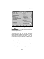
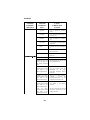
Contents
INTRODUCTION........................................................................
xiii
1. CHAPTER 1 GETTING STARTED .....................................
1.1 ABOUT CEC/IMC MANAGER V5.0..........................
1.2 ABOUT THIS MANUAL..............................................
1.2.1 System Configuration .............................................
1.2.2 System Monitoring .................................................
1.2.3 Help ........................................................................
1.3 DATA LOGGING FEATURE......................................
1-1
1-1
1-1
1-2
1-4
1-4
1-5
2. CHAPTER 2 INSTALLATION.............................................
2.1 UNPACKING.................................................................
2.2 CEC/IMC MANAGER REQUIREMENTS ................
2.3 DISKETTE HANDLING ..............................................
2.4 MAKING BACKUPS ....................................................
2.5 MULTIPLE REMOTE CLIENTS ...............................
2.6 UPGRADE CEC/IMC MANAGER .............................
2.7 SYSTEM HOOK-UP.....................................................
1-1
2-1
2-1
2-2
2-2
2-3
2-3
2-7
3. CHAPTER 3 OPERATION AND CONFIGURATION...... 2-1
3.1 STARTING THE PROGRAM ..................................... 3-1
3.1.1 Default User Account ............................................. 3-1
3.2 USER ACCOUNT CONFIGURATION ...................... 3-3
3.2.1 Set Up Accounts ..................................................... 3-5
3.2.2 Modify Accounts .................................................... 3-7
3.3 CEC/IMC MANAGER FONT SELECTION.............. 3-8
3.4 INITIAL CEC/IMC MANAGER AND MOM
CONTROLLER BOARD CONFIGURATION ................. 3-10
3.5 SYSTEM TIME AND DATE........................................ 3-12
3.6 SYSTEM MANAGER DATABASE UPLOADS ........ 3-14
3.6.1 Transfer From System Manager ............................. 3-17
3.6.2 Transfer From CEC/IMC Manager......................... 3-18
3.7 TDM BUS CONFIGURATION.................................... 3-19
3.8 SITE-TYPE INTERFACE MODULE CHANNEL
CONFIGURATION.............................................................. 3-21
3.8.1 MIM Channel Configuration .................................. 3-23
3.8.2 NIM Channel Configuration ................................... 3-46
3.8.3 PIM Channel Configuration.................................... 3-64
3.8.4 VMIM Channel Configuration................................ 3-82
3.8.5 CTIM Channel Configuration................................. 3-91
3.9 CONFIRMED CALL .................................................... 3-100
3.10 TELEPHONE INTERCONNECT .............................. 3-103
vii
LBI-39224
3.11 CONSOLE CONFIGURATION ................................. 3-104
3.11.1 CIM Channel Configuration ................................. 3-105
3.11.2 Console User Profile Configuration...................... 3-112
3.11.3 C3 Maestro Console Hardware Configuration...... 3-121
3.11.4 Console Privilege Lists ......................................... 3-123
3.11.5 C3 Modular/Desktop Console Configuration ....... 3-127
3.11.6 View Patch/Simulselect ........................................ 3-130
3.12 DIGITAL VOICE CHANNEL
CONFIGURATION.............................................................. 3-132
3.12.1 DVIM Selection.................................................... 3-133
3.12.2 DVIM Configuration ............................................ 3-135
3.12.3 Digital Causeway (Causeway Default to
Digital)............................................................................. 3-140
3.13 DISTRIBUTED MULTISITE / STARGATE
CONFIGURATION.............................................................. 3-141
3.14 CONVENTIONAL CHANNEL
CONFIGURATION.............................................................. 3-145
3.14.1 StarGate Network Conventional Channels ........... 3-145
3.14.2 Causeway Patch / Simulselect............................... 3-152
3.14.3 Conventional Channel Configuration.................... 3-155
3.15 LOGGING RECORDER CONFIGURATION.......... 3-174
3.15.1 LRIM Module Configuration................................ 3-175
3.15.2 Save and Send LRIM Module Configurations...... 3-177
3.16 EDACS DATA GATEWAY (EDG)
CONFIGURATION.............................................................. 3-178
3.17 CENTRALIZED ACTIVITY LOGGER (CAL)
CONFIGURATION.............................................................. 3-179
3.18 AUXILIARY I/O CONFIGURATION ....................... 3-179
3.18.1 I/O Event Configuration ....................................... 3-180
3.19 ACTIVATE TDM BUS SLOTS................................... 3-187
3.20 MULTISITE UNIT LOGOUT
CONFIGURATION.............................................................. 3-188
3.20.1 Unit Timed Logout Configuration ........................ 3-192
3.20.2 Command Unit Logout ......................................... 3-194
3.20.3 Location Request .................................................. 3-194
3.20.4 Multisite Settings .................................................. 3-197
3.21 WWVB TIME STANDARD CONFIGURATION..... 3-199
3.22 REDUNDANT CLOCK ............................................... 3-199
3.23 PROSOUND CONFIGURATION .............................. 3-203
3.24 EXITING THE PROGRAM........................................ 3-207
4. CHAPTER 4 MONITOR SYSTEM......................................
4.1 SYSTEM MONITORING.............................................
viii
3-1
4-1
LBI-39224
4.2 NODE DATA .................................................................
4.2.1 Node Matrix............................................................
4.2.2 Board Identification................................................
4.3 FEATURE DATA ..........................................................
4.3.1 Licensed Features ...................................................
4.3.2 Licensed Capacities ................................................
4.4 DIAGNOSTICS .............................................................
4.4.2 Diagnostic Options .................................................
4.5 STATISTICS..................................................................
4.5.1 HDLC Statistics ......................................................
4.5.2 GSC Node Statistics ...............................................
4.5.3 NIM Statistics .........................................................
4.5.4 TEC (T1/E1 Interface Card) Status and Statistics ..
4-1
4-2
4-4
4-6
4-7
4-7
4-9
4-10
4-18
4-18
4-21
4-24
4-26
5. CHAPTER 5 OFF-LINE DIAGNOSTICS ...........................
5.1 OFF-LINE DIAGNOSTIC FUNCTIONS ...................
5.1.1 CALLS.EXE...........................................................
5.1.2 GSCMON.EXE ......................................................
5-1
5-1
5-1
5-4
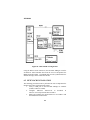
6. CHAPTER 6 NETCLOCK/2™ INTERFACE OPTION ....
6.1 OVERVIEW...................................................................
6.2 NETCLOCK INSTALLATION ...................................
6.2.1 Hardware Installation Notes ...................................
6.2.2 Software Installation Notes.....................................
6.2.3 Additional Considerations ......................................
6.3 INSTALLATION VERIFICATION ............................
4-1
6-1
6-2
6-3
6-5
6-5
6-6
7. APPENDIXES .......................................................................... A-6-1
7.1 APPENDIX A - LOGGED ERROR DEFINITIONS.. A-1
7.2 APPENDIX B - LOGGED WARNING
DEFINITIONS ...................................................................... B-1
7.3 APPENDIX C - SNMP AGENT and PROXY for
CEC/IMC (Optional)............................................................ C-1
7.4 APPENDIX D - FONT SELECTABLE DIALOG
BOXES................................................................................... D-1
7.5 APPENDIX E - POPUP MESSAGE BOX
DEFINITIONS ...................................................................... E-1
GLOSSARY..................................................................................
G-1
INDEX...........................................................................................
I-1
ix
LBI-39224
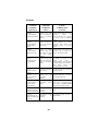
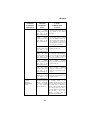
List of Figures
Figure 1
Figure 2
Figure 3
Figure 4
Figure 5
Figure 6
Figure 7
Figure 8
Figure 9
Figure 10
Figure 11
Figure 12
Figure 13
Figure 14
Figure 15
Figure 16
Figure 17
Figure 18
Figure 19
Figure 20
Figure 21
Figure 22
Figure 23
Figure 24
Figure 25
Figure 26
Figure 27
CEC/IMC Manager Main Window and Menu Bar ....... 3-2
CEC/IMC Manager Login ............................................ 3-2
CEC/IMC Manager Configuration Menu ..................... 3-4
CEC/IMC Manager Configuration User Menu............. 3-5
Add/Modify/Delete Users Dialog Box ......................... 3-6
Font Selection Dialog Box............................................ 3-9
CEC/IMC Manager Configuration Dialog Box ............ 3-10
System Options Menu................................................... 3-13
Configure System Clock Synchronization Dialog Box. 3-13
System Mgr/Network Mgr Entity Database Dialog Box 3-16
TDM Bus Configuration Dialog Box ........................... 3-20
CEC/IMC Configuration Menu .................................... 3-23
Site Channel Configuration List Dialog Box
(MIM Shown) ............................................................... 3-24
Audio Interface Type Dialog Box
(Audio Board selected) ................................................. 3-27
Audio Interface Type Dialog Box
(T1/E1 Interface Card selected) .................................... 3-28
Site Audio Channel Configuration Dialog Box
(MIM Shown) ............................................................... 3-29
"Save As…" Dialog Box .............................................. 3-34
T1/E1 Digital Site Configuration Dialog Box
(T1 Line Type Selected) .............................................. 3-39
T1/E1 Interface Card Auto-configuration dialog box
(T1 Line Type Selected) .............................................. 3-42
NIM Site Channel Configuration List Dialog Box ....... 3-48
NIM Site Channel Configuration Dialog Box............... 3-50
VMIM Configuration Menu ......................................... 3-83
System Options Dialog Box.......................................... 3-101
Console Configuration Menu........................................ 3-105
Console Channel Configuration List Dialog Box ......... 3-106
Console Channel Configuration Dialog Box ................ 3-108
Console User Profile Configuration Dialog Box .......... 3-113
x
LBI-39224
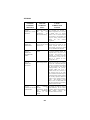
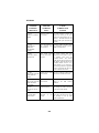
Figure 28 C3 Maestro Hardware Configuration Dialog Box ........ 3-121
Figure 29 Console Privilege List Dialog Box ............................... 3-125
Figure 30 C3 Modular/Desktop Console Configuration
Dialog Box.................................................................... 3-127
Figure 31 Patch and Simulselect View Dialog Box ...................... 3-131
Figure 32 DVIM Channel Configuration List Dialog Box............ 3-135
Figure 33 DVIM Channel Configuration Dialog Box................... 3-136
Figure 34 StarGate / Remote CEC / NIM Configuration
Dialog Box.................................................................... 3-142
Figure 35 Conventional Channel Configuration Dialog Box ........ 3-149
Figure 36 Tone Controlled Station State Table Mapping
Dialog Box................................................................... 3-168
Figure 37 DC Controlled Station State Mapping Dialog Box....... 3-171
Figure 38 Logging Recorder Configuration Dialog Box............... 3-174
Figure 39 LRIM Module Edit Dialog Box.................................... 3-175
Figure 40 Auxiliary I/O Event Configuration Dialog Box ............ 3-180
Figure 41 Activate TDM Bus Slots............................................... 3-188
Figure 42 Unit/Group Location and Unit Logout Dialog Box ...... 3-189
Figure 43 ProSound-Site Adjacency Configuration Dialog Box... 3-204
Figure 44 Monitor System Menu .................................................. 4-1
Figure 45 CEC/IMC Diagnostics (Node Matrix) Screen .............. 4-2
Figure 46 Board Identification Dialog Box................................... 4-4
Figure 47 Active Devices Dialog Box .......................................... 4-10
Figure 48 Diagnostics Dialog Box, Errors Option Selected.......... 4-11
Figure 49 Diagnostics Dialog Box, Warnings Option Selected .... 4-13
Figure 50 Diagnostics Dialog Box,
Call Translation Option Selected .................................. 4-15
Figure 51 Diagnostics Dialog Box, GSC Data Option Selected ... 4-16
Figure 52 Diagnostics Dialog Box,
GSC Translation Option Selected ................................. 4-17
Figure 53 Monitor System Statistics Menu ................................... 4-18
Figure 54 HDLC (Channel B) Statistics Dialog Box .................... 4-19
Figure 55 GSC Node Statistics Dialog Box .................................. 4-22
Figure 56 NIM Statistics Dialog Box............................................ 4-24
Figure 57 T1/E1 Card Status and Statistics Dialog Box ............... 4-26
xi
LBI-39224
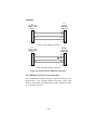
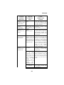
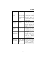
Figure 58 NETCLOCK/2 Configuration.......................................
Figure 59 NETCLOCK/2 T-CMD Interconnections.....................
Figure 60 NETCLOCK/2 Remote Output Connections................
6-2
6-4
6-5
List of Tables
Table 1
Table 2
Table 3
Table 4
Table 5
Table 6
Table 7
Table 8
Table 9
Table 10
Table 11
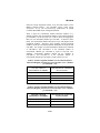
Configured/Active Sites Prefix Definitions.................... 3-25
Subrate Port Assignments for Analog/Modem Mode .... 3-43
Synchronous Subrate Port Packing Arrangement .......... 3-44
Console Individual Call Levels...................................... 3-119
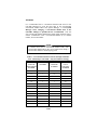
Switch Assignment Number-to-Conventional Channel
Allocation Mapping for StarGate Networks
(Max. Conv. Channels per CEC/IMC = 64)................... 3-147
Switch Assignment Number-to-Conventional Channel
Allocation Mapping for StarGate Networks
(Max. Conv. Channels per CEC/IMC = 32)................... 3-147
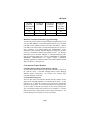
Conventional Channel Locations
(Example with Max. Conv. Channels per CEC/IMC = 64)
(Non-Inclusive Listing) .................................................. 3-150
Conventional Base Station Commands .......................... 3-166
DC Controlled Station State Configuration.................... 3-172
DC Controlled Station State Mapping ........................... 3-172
Licensed MSC Type ...................................................... 4-8
xii
LBI-39224
INTRODUCTION
Welcome
Ericsson welcomes you to the world of mobile communications. We
believe there is no equal to Ericsson products and have made a
commitment to our customers to ensure that product satisfaction and
reliable service is our number one priority.
Quality built and dependable, the CEC/IMC Manager, or Monitor
Module (MOM) PC, is a tool designed to monitor and configure the
CEC/IMC Digital Audio Switch.
About Your CEC/IMC Manager Operations Guide
This manual, written to give you a clear and concise understanding of
the CEC/IMC Manager (MOM PC), is only one part of the CEC/IMC
Manager Version 5.0 for Windows NT® documentation. Also included
is an extensive on-line Help system when you set up CEC/IMC
Manager Version 5.0 for Windows NT.
The following list outlines the various pieces of the CEC/IMC Manager
for Windows NT documentation.
–
The EDACS CEC/IMC Manager Operations Guide (this
manual) includes a guide to setting up CEC/IMC Manager for
Windows NT on your system and a brief introduction to
CEC/IMC Manager for Windows NT. Along with on-line
Help, this manual also provides a comprehensive guide to
using CEC/IMC Manager for Windows NT. It includes
explanations and procedures for first-time and advanced users.
–
On-line Help provides a quick reference to procedures and
commands you need when using CEC/IMC Manager for
Windows NT. Context sensitive Help is also available, to
obtain specific information about how to complete a dialog
box, press F1 or choose the Help command button while using
the dialog box.
xiii
LBI-39224
Conventions
Those users already familiar with Windows® will feel quite at home
with the graphical aspects of CEC/IMC Manager for Windows NT. For
those users who are not very familiar with Windows, or are a bit rusty, a
brief review follows.
–
An application window contains a running application, has a
title bar, menu bar, and status bar.
–
A document window may appear inside an application
window, this type of window may contain documents, data
files, groups, or directories.
–
A window can be moved, changed in size, and reduced to an
icon.
–
The title bar shows the name of the application.
–
The menu bar contains the available menus from which you
can choose commands.
–
The status bar displays various status updates such as the
current time, or a description of the currently selected menu
option.
–
Selecting (single-clicking) an item usually means marking it
with the selection cursor, which can then appear as a highlight,
a dotted rectangle, or both; selecting alone does not start an
action.
–
Choosing (single-clicking) an item carries out an action;
starting an application, opening a window, or carrying out a
command, i.e. you choose an item from a menu and choose a
command in a dialog box.
–
A dialog box appears when you need to supply additional
information to complete a task.
–
A text box requires typed information by the user.
–
A list box displays a list of choices, if there are more choices
than can fit in the box scroll bars are provided so you can
move quickly through the list.
–
A drop-down list box appears initially as a rectangular box
containing the current selection, when the down arrow in the
square box at the right is selected a list of available choices
xiv
LBI-39224
–
appears, scroll bars are provided if there are more choices
than can fit in the box.
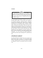
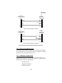
–
Check boxes present non-exclusive options, you can select as
many options as needed, when a check box is selected it
contains an X, names of unavailable options appear dimmed.
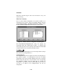
Option 1
(unselected)
Option 1
(selected)
–
Command buttons provide instant access to or activation of
commonly used operating functions, most dialog boxes have
several command buttons located near the bottom of the dialog
box (choose a command button to initiate an action).
Save
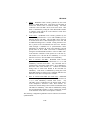
–
Option buttons represent a group of mutually exclusive
options; you can select only one option at a time, if you
already have one option selected your current selection
replaces it, the names of unavailable options appear dimmed.
Option A
Option B
Option C
(second option, "Option B," selected)
To help you recognize needed information easily, CEC/IMC Manager
for Windows NT will use consistent visual and text formats.
–
Dialog box titles and menu choices will be designated by the
following text style: TDM Bus Slots, Configure System.
–
Text boxes, list boxes, fields, etc. within dialog boxes will be
designated by first letter in upper case: Channel Signaling text
box, Configurable Sites list box, User Name fields.
–
Command buttons will be introduced for a particular dialog
box as follows:
Save
and will be designated within the text as: Save.
xv
LBI-39224
This page intentionally blank
xvi
LBI-39224
1. CHAPTER 1
GETTING STARTED
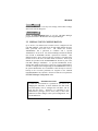
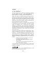
1.1 ABOUT CEC/IMC MANAGER V5.0
Starting with release (version) 5.0 the CEC/IMC Manager is a 32 bit
Windows NT application. To provide remote management capability
the architecture of the CEC/IMC Manager is Client/Server. The
application is divided into two executables; GUI_SRVR.exe is the
Server application that runs as a Windows NT service, and W_GUI.exe
is the Graphical User Interface (GUI) application run from the ICON
selected in the WINMOM program group. This release of CEC/IMC
Manager also includes an optional SNMP agent that runs as a Windows
NT service. The SNMP agent is required to provide a Network
Management station remote monitoring of the CEC/IMC Manager
directly and the CEC/IMC by proxy. The installation procedure for this
agent is found in APPENDIX C - SNMP AGENT and PROXY for
CEC/IMC (Optional).
Once installed, configure the agent in
accordance with the configuration procedures in EDACS® Network
Management Installation and Technical Reference Manual (LBI39171).
Throughout this program there will be references to configuration data
saved to, stored at, and read/retrieved from the CEC/IMC Manager hard
disk. This hard disk is located at the machine (PC) that the
GUI_SRVR.exe is running from, not the machine running the GUI
application unless the same machine is performing both services. In
most cases, if not all, the machine running the server (GUI_SRVR.exe)
will be local to the CEC/IMC.
The CEC/IMC Manager for Windows NT Client has been ported to
HP-UX platforms to run in conjunction with Network Manager. For
users running an HP-UX version of the CEC/IMC Manager Client all
references in this manual to W_GUI.exe, Graphical User Interface
(GUI), or CEC/IMC Manager for Windows NT Client should be
considered "CEC/IMC Manager HP-UX Client."
1.2 ABOUT THIS MANUAL
This manual describes the CEC/IMC Manager (MOM PC) user
interface and functions. It is intended to aid the user in performing
various CEC/IMC Manager functions such as CEC/IMC configuration
1-1
LBI-39224
and viewing interface module status data. The various screens and
terms the user may encounter are walked through and explained in full
detail. The following sub-sections highlight the major functions of the
CEC/IMC Manager.
1.2.1 System Configuration
CEC/IMC Manager Configuration
–
CEC/IMC Manager User Profiles – Configure CEC/IMC
Manager user accounts. This includes user names, passwords,
and access levels.
–
CEC/IMC Manager Hardware – Set serial interface baud
rates for System Manager and CEC/IMC Manager,
enable/disable data logging, and set the datalog threshold
number.
–
CEC/IMC Manager Font Selection – Select font type and
size for optimum compatibility with Network Manager
platforms.
CEC/IMC Configuration
–
Trunked and Console Channels – Adjust audio levels and
other related parameters for each site-type, console, and
EDACS Data Gateway™ (EDG) interface.
–
Conventional Channels – Adjust audio levels, type of control
(tone, dc, etc.), and other related parameters for conventional
channel interfaces. Set conventional channels for Causeway
patch or Causeway simulselect operation.
–
Digital Voice Channels – Configure digital voice channels for
either pooled (dynamic) or dedicated call assignment
operation.
–
Logging Recorders – Configure logging recorder parameters
such as output level and assigned entity (unit, group, etc.).
–
TDM Buses – Configure the number of TDM buses to match
number of buses supported by the installed CEC/IMC Audio
Boards.
–
TDM Bus Time Slots – Allocate the number of TDM bus
time slots required by each site-type, console, digital voice,
1-2
LBI-39224
and EDACS Data Gateway (EDG) interface. In release 5.0
CEC/IMC Manager TDM bus time slots are allocated from
each site, console, or DVIM interface audio configuration
dialog box.
System Options
–
Auxiliary I/O – Program auxiliary I/O events.
–
Multisite Unit Logout – Configure multisite unit logout
parameters for each unit, both timer-based and instant
command logouts are provided View unit and group location
information.
–
Confirmed Call – Configure confirmed call options, exempt
sites from confirmation process and enable automatic
confirmed call database repair.
–
ProSound – Configure ProSound™ site adjacency
information for each site. This information is used during
wide area scan operations.
–
File Transfer – Transfer unit, group, and site databases from
the System Manager to the CEC/IMC Manager. Distribute
System Manager database information stored at the CEC/IMC
Manager to CEC/IMC interface modules.
–
Distributed Multisite/StarGate Networks – Configure
Network Interface Module (NIM) and StarGate network
options such as NIM baud rates, NIM audio channel
parameters, and conventional channel settings.
–
Time and Date – Set system time and date source. This can be
broadcast throughout the entire CEC/IMC for time
synchronization. Also configure the NETCLOCK/2 interface
(optional).
–
Digital Console Pre-empt – Digital console pre-empt allows
for console pre-empting of digital calls. (This feature may
require Site Controller or GETC™ interface and radio
software changes.)
–
Telephone Interconnect – The modifications allow "Caller
ID" on inbound interconnect calls, and Multiple Jessica
options on StarGate systems.
1-3
LBI-39224
Console Configuration
–
Console Hardware Configuration – Perform special console
hardware configurations for C3 Maestro™ consoles.
–
Console User Profiles – Configure console user-specific
parameters. Up to ten (10) different console user profile
set-ups (shifts) are available for each console.
–
Console Privilege Lists – Assign unit, group,
conventional channel privileges to each console.
–
C3 Modular/Desktop Consoles – Perform special console
configurations for C3™ Modular/Desktop consoles.
–
View Patch/Simulselect – View the various patches and
simulselects established within the CEC/IMC system.
and
1.2.2 System Monitoring
–
View Node Data – View status and errors on an interface
module-by-interface module basis.
–
Feature Data – View currently licensed features and
capacities.
–
Diagnostics – View interface module (CAM, CIM, CTIM,
DVIM, LRIM, MIM, MOM, etc.) errors and messages on an
interface module-by-interface module basis.
–
Statistics – View interface module (CAM, CIM, CTIM,
DVIM, LRIM, MIM, MOM, etc.) statistics, their assignments,
and associated GSC node address on an interface module-byinterface module basis. Also reports Global Serial Channel
(GSC) Bus loading.
1.2.3 Help
–
Help – On-line Help provides a quick reference to procedures
and commands you will need when using the CEC/IMC
Manager. Context sensitive Help is available to provide
specific information about how to complete a dialog box.
1-4
LBI-39224
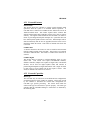
1.3 DATA LOGGING FEATURE
One of the most important features of the CEC/IMC Manager
(MOM PC) is its ability to log data. All data that is placed on the GSC
Bus in the CEC/IMC is logged at the MOM Controller Board. The
MOM Controller Board then periodically dumps its data log buffer to
the CEC/IMC Manager through their serial link. The CEC/IMC
Manager writes this data to its hard disk, where it can be extracted and
viewed either on- or off-line. The on-line functions are available under
System Monitoring Diagnostics. The off-line functions are:
CALLS.EXE
Used to extract all calls made within the
CEC/IMC.
GSCMON.EXE
Used to extract all messages from the logged
data.
1-5
LBI-39224
This page intentionally blank
1-6
LBI-39224
2. CHAPTER 2
INSTALLATION
2.1 UNPACKING
After opening this package, verify you have received the following:
–
CEC/IMC Manager Version 5.0 for Windows NT software—
located on 3-1/2 inch diskettes; this software will be already
installed on the computer's hard drive for a new system
–
this manual (LBI-39224)
2.2 CEC/IMC MANAGER REQUIREMENTS
The following minimum hardware and software configuration is
required to operate the CEC/IMC Manager V5.0x.
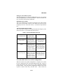
A. An IBM® Compatible PC with a 75 MHz Pentium® microprocessor
(or better) running Microsoft® Windows NT V3.51 (or better) with
the following minimum configuration:
–
Service Pack #3 or better installed
–
At least 16 Mbytes of RAM
–
A 540 Mbyte hard disk
–
Two (2) serial ports
B. VGA video card and monitor (or better).
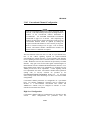
IMPORTANT NOTE!
Ensure that the MIGRATE.BAT utility supplied with the
"CEC/IMC Manager Version 5.0 for Windows NT" software
is executed to save that original (DOS) CEC/IMC Manager
configuration BEFORE installing Windows NT on any
computer already running a DOS version of the CEC/IMC
Manager.
2-1
LBI-39224
2.3 DISKETTE HANDLING
While working with your diskettes you should consider the following
handling procedures:
–
Always store diskettes in their envelope
–
Insert diskettes into the drive carefully
–
Use only felt tipped pens to write on a diskette label
–
Store diskettes at a comfortable room temperature
–
Refrain from touching the recording surface
–
Do not bend the diskettes
–
Do not allow any form of liquid to come in contact with the
diskette surface
–
Keep diskettes away from magnetic fields as found in
electronic equipment.
If you follow these simple guidelines you will receive long service from
your diskettes.
2.4 MAKING BACKUPS
This software is provided on 3-1/2 inch diskettes labeled "CEC/IMC
Manager V5.0 for Windows NT." These diskettes are very sensitive
and fragile, and should be handled with care and stored in a secure area.
NOTE
The CEC/IMC Manager software is pre-installed at the factory
(WINMOM directory) for new systems.
We recommend that upon receipt of your original diskettes you store
them in a safe place. This ensures the availability of an accurate
program should the installed program fail during operation.
2-2
LBI-39224
NOTE
It is important to use the DISKCOPY command when making
a backup and not the COPY or XCOPY commands. The
diskette contains a volume label that is required for the
installation process and COPY and XCOPY do not copy
volume labels.
2.5 MULTIPLE REMOTE CLIENTS
The CEC/IMC Manager Remote Client (W_GUI.exe) can be executed
from any PC that is running Windows NT v3.51 or better and
connected to the same LAN as the desired CEC/IMC Manager server.
A maximum of ten (10) remote clients are supported.
Single CEC/IMC Manager (No LAN)
NO command line options are necessary for the Local CEC/IMC
Manager if the default machine name was selected for the Local
CEC/IMC Manager machine (default = "MOM_NT").
Multiple CEC/IMC Managers on LAN
If ANY other machine name is used other than the default machine
name (default = "MOM_NT"), the following action must be performed.
Depending on the LAN Transport one of the following "command line
options" MUST be added to the File/Properties dialog box:
COMMAND LINE OPTIONS for Remote Client (network
connection)
W_GUI.exe <machine name> Networks without TCP/IP
W_GUI.exe
<IP address> TCP/IP networks
See Figure 1 in the following chapter for an example of a CEC/IMC
Manager on a TCP/IP network, the IP address is displayed in the
CEC/IMC Manager main window title bar. Figure 3 is an example of a
CEC/IMC Manager set up as a single (Local) CEC/IMC Manager.
2.6 UPGRADE CEC/IMC MANAGER
NOTE
Ensure that the requirements of MULTIPLE REMOTE
CLIENTS (Step 2.5 above) are fulfilled before proceeding.
2-3
LBI-39224
1.
VERIFY that the MIGRATE.BAT utility has been executed to
save the original (DOS) CEC/IMC Manager configuration.
2.
Insert the "Install" CEC/IMC Manager V5.0 for Windows NT
diskette and execute SETUP.EXE. This setup utility will:
– Copy all necessary Executables and DLLs
– Install the CEC/IMC Manager server as a service
– Install the CEC/IMC Manager GUI
– Setup Program Groups and CEC/IMC Manager Icons
– Execute the necessary registry edits
3.
(OPTIONAL) Insert the "Install" SNMP Agent Diskette and
execute SETUP.EXE.
4.
Insert the "Migrate Utility" diskette and execute
MIGRATE.BAT to transfer the previous (DOS) CEC/IMC
Manager configuration to the just installed (Windows NT)
CEC/IMC Manager.
This should be the second time
MIGRATE.BAT was run since the original (DOS) CEC/IMC
Manager configuration was saved using this utility on the
(DOS) CEC/IMC Manager machine. In a DOS Window:
From the C:\WINMOM prompt type a:\migrate TO.
5.
Reboot the CEC/IMC Manager PC.
6.
Double-click on the CEC/IMC Manager icon (in the
WINMOM program group) to execute the CEC/IMC Manager
GUI.
IMPORTANT NOTE
Expect to see "NOVRAM MISMATCH" Popup windows.
These occur because the DOS MOMPC did not save Bus/Slots
to disk. Although the Migration utility preserved much of the
configuration, the bus/slots at the CEC/IMC Manager will be
zero and the MOM Controller will hold the valid Bus/Slots
configuration. By following steps 7-13 the entire slot database
should be stored to the CEC/IMC Manager V5.0 hard disk.
2-4
LBI-39224
7.
The TDM Bus/Slots must be read from the CEC/IMC in the
Console Audio Configuration screens.
a) Select Menu Option Configure System / CEC/IMC
Configuration / CIM.
b) Select ALL consoles that are displayed in the
Configured/Active Consoles list box.
c)
Choose the Modify button.
d) For each console push the CEC/IMC to Disk button.
e) Verify the Slots match in the Upper and Lower list boxes
for ALL channels.
8.
The TDM Bus/Slots must be read from the CEC/IMC in the
CTIM Audio Configuration screens.
a) Select menu option Configure System / CEC/IMC
Configuration / CTIM.
b) Select ALL CTIMs that are displayed in the
Configured/Active Sites list box.
c)
Choose the Modify button.
d) For each CTIM push the CEC/IMC to Disk button.
e) Verify the Slots match in the Upper and Lower list boxes
for ALL channels.
9.
The TDM Bus/Slots must be read from the CEC/IMC in the
Site Audio Configuration screens.
a) Select menu option Configure System / CEC/IMC
Configuration / MIM.
b) Select ALL sites that are displayed in the
Configured/Active Sites list box.
c)
Choose the Modify button.
d) For each site choose the CEC/IMC to Disk button.
e) Verify the Slots match in the Upper and Lower list boxes
for ALL channels.
10. The TDM Bus/Slots must be read from the CEC/IMC in the
PIM Audio Configuration screens.
a) Select menu option Configure System / CEC/IMC
Configuration / PIM.
b) Select ALL PIMs that are displayed in the
Configured/Active Sites list box.
2-5
LBI-39224
c)
Choose the Modify button.
d) For each PIM choose the CEC/IMC to Disk button.
e) Verify the Slots match in the Upper and Lower list boxes
for ALL channels.
11. The TDM Bus/Slots must be read from the CEC/IMC in the
NIM Audio Configuration screens.
a) Select menu option Configure System / CEC/IMC
Configuration / NIM.
b) Select ALL NIMs that are displayed in the
Configured/Active Sites list box.
c)
Choose the Modify button.
d) For each NIM choose the CEC/IMC to Disk button.
e) Verify the Slots match in the Upper and Lower list boxes
for ALL channels.
12. The TDM Bus/Slots must be read from the CEC/IMC in the
DVIM Audio Configuration screens.
a) Select menu option Configure System / CEC/IMC
Configuration / DVIM.
b) Select ALL DVIMs that are displayed in the
Configured/Active DVIM list box.
c)
Choose the Modify button.
d) For each DVIM choose the CEC/IMC to Disk button.
e) Verify the Slots match in the Upper and Lower list boxes
for ALL channels.
13. The TDM Bus/Slots must be read from the CEC/IMC in the
VMIM Audio Configuration screens.
a) Select menu option Configure System / CEC/IMC
Configuration / VMIM / Audio Configuration.
b) Select ALL VMIMs that are displayed in the
Configured/Active Sites list box.
c)
Choose the Modify button.
d) For each VMIM choose the CEC/IMC to Disk button.
e) Verify the Slots match in the Upper and Lower list boxes
for ALL channels.
2-6
LBI-39224
14. Any T1/E1 node databases must be defined or converted from
analog to T1 or E1. See the T1/E1 Installation Instructions for
more details on setting the T1/E1 databases.
2.7 SYSTEM HOOK-UP
Connect all peripheral equipment to your computer prior to configuring
the software items described in Chapter 3 of this manual. Refer to the
operating manuals of each device for correct installation procedures.
Also see CEC/IMC Digital Audio Switch Installation, Set-Up and
Troubleshooting (LBI-38938) for interconnection details. Upgrade all
software/firmware at the CEC/IMC Controller and Audio Boards as
described in CEC/IMC Manager V5.0 for Windows NT® Release Notes
(350A1874).
If your system is already established, verify you have all the equipment
necessary to execute the program and isolate all connecting cables to
prevent tangling, interference, and damage.
2-7
LBI-39224
This page intentionally blank
2-8
LBI-39224
3. CHAPTER 3
OPERATION AND CONFIGURATION
The primary intent of this chapter is to describe CEC/IMC Manager
program operation, and valid CEC/IMC Manager and CEC/IMC Digital
Audio Switch configuration settings. In some cases detailed systemlevel information is presented where necessary. This chapter is
arranged in the order recommended for the set-up of a new CEC/IMC
Digital Audio Switch. Refer to the set-up information within
LBI-38938 and other referenced documents for additional information
as necessary.
3.1 STARTING THE PROGRAM
This chapter assumes that program software loading and system
hookups have been completed. The program software is installed at the
factory for new systems; however, refer to Section 2.7, SYSTEM
HOOK-UP of the previous chapter if system hookup has not been
accomplished.
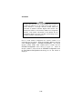
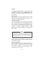
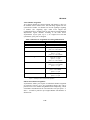
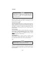
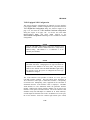
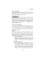
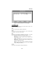
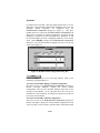
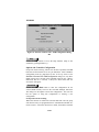
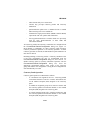
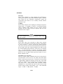
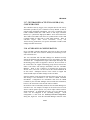
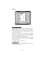
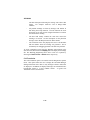
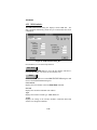
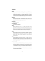
3.1.1 Default User Account
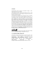
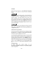
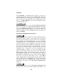
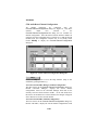
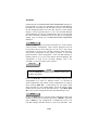
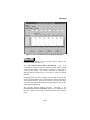
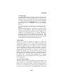
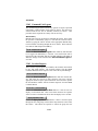
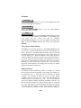
From the Windows NT Program Manager open the CEC/IMC Manager
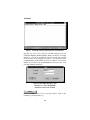
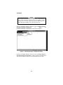
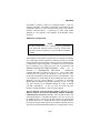
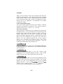
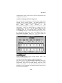
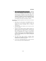
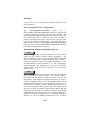
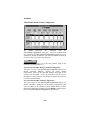
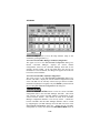
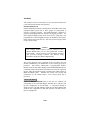
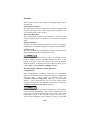
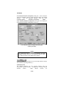
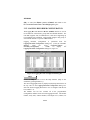
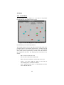
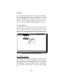
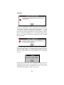
program and the CEC/IMC Manager main menu (Figure 1) will be
displayed.
The bottom status bar displays several messages that are helpful or
important to the CEC/IMC Manager user. "For Help, press F1" or the
current menu choice and the current time are displayed at each end of
the status bar. System status—"No System Errors" or "System
Errors"—and Link status—"Mom Link is Up" or "Mom Link is
Down"—provide the user with important information concerning
system operation.
3-1
LBI-39224
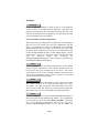
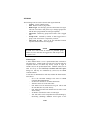
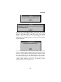
Figure 1 CEC/IMC Manager Main Window and Menu Bar
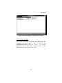
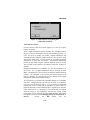
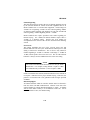
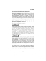
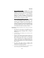
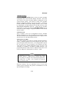
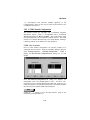
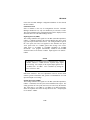
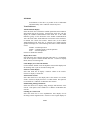
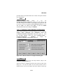
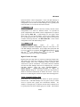
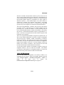
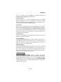
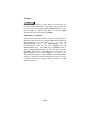
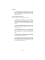
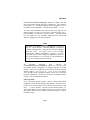
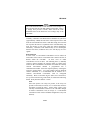
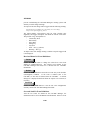
Selecting any of the choices from the CEC/IMC Manager menu bar
(Configure System, Monitor System, Help) will display the Login
dialog box. You will be prompted to enter a user name and password
before execution of the program will continue. The default user name
is "MOMUSER" and the default password is "GUEST." These log-in
defaults are provided in the PASSWORD.DAT file that is part of the
CEC/IMC Manager installation.
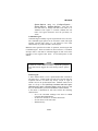
Figure 2 CEC/IMC Manager Login
Default User Name: MOMUSER
Default User Password: GUEST
Help
Choose the Help button to access the Help function. (Help is also
available by pressing the F1 key.)
3-2
LBI-39224
OK
Choose the OK button to save any new settings, activate those settings,
and exit the current dialog box.
Exit Program
Choose the Exit Program button to exit the CEC/IMC Manager
program and return to the Windows NT Program Manager.
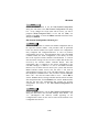
3.2 USER ACCOUNT CONFIGURATION
Up to twelve (12) different user accounts can be configured for the
CEC/IMC Manager. Each user has an account which defines the user's
name, password, and access level.
The default user account,
"MOMUSER," has a password of "GUEST" and a "System
Administrator" access level. For Network Manager stations the default
user account is "NMUSER" and has a password of "GUEST." This
default account is active the first time the program is executed and it
remains as one of the twelve accounts unless it is deleted. These log-in
defaults are provided in the PASSWORD.DAT file that is part of the
CEC/IMC Manager installation. To prevent unauthorized access,
deleting this default account after at least one "System Administrator"
account is configured and safeguarding the PASSWORD.DAT file by
the system administrator are recommended. This file may be used as a
backup in the event that passwords are forgotten or the installed
PASSWORD.DAT file is deleted. All user accounts are set up from the
CEC/IMC Manager Configuration menu.
IMPORTANT NOTE!
In multi-user environments it is possible for two users to be
changing the same data. In these situations, the data saved,
and subsequently used to configure the CEC/IMC, will be
from the last "Save." Therefore, it is important to give
administrative privileges (access level) only to those users
authorized to make changes to the system configuration. See
also NOTE below.
3-3
LBI-39224
NOTE
Certain menu selections may be "grayed-out," indicating that
those menu selections (functions) are not available to that
access level. See User Access Level (later in this section) for
those functions available to the various access levels.
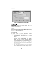
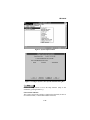
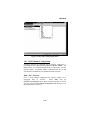
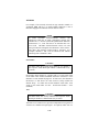
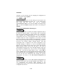
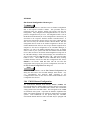
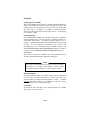
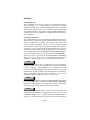
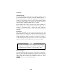
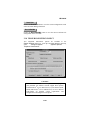
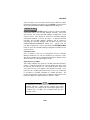
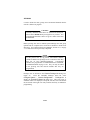
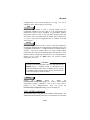
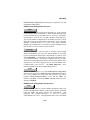
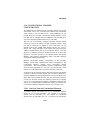
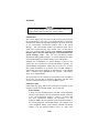
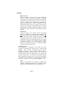
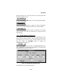
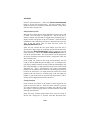
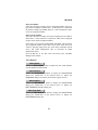
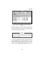
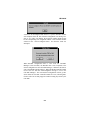
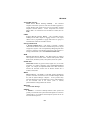
From the CEC/IMC Manager menu bar select Configure System /
CEC/IMC Manager Configuration
to
display
the
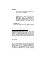
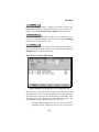
CEC/IMC Manager Configuration menu, shown in Figure 3.
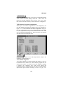
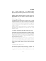
Figure 3 CEC/IMC Manager Configuration Menu
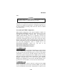
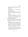
From the CEC/IMC Manager menu bar select Configure System /
CEC/IMC Manager Configuration / User to display the User menu.
This menu provides the means to set-up and modify user accounts.
3-4
LBI-39224
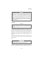
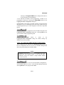
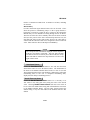
Figure 4 CEC/IMC Manager Configuration User Menu
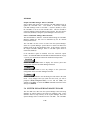
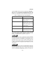
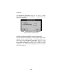
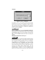
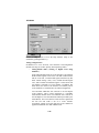
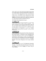
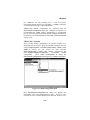
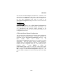
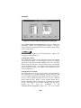
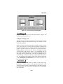
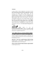
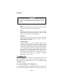
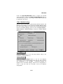
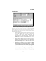
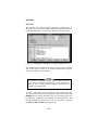
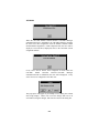
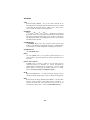
3.2.1 Set Up Accounts
This option is used to add a new user account. Adding a new user
account involves adding the new user name, selecting a password, and
establishing the access level.
This is done in the
Add/Modify/Delete Users dialog box, Figure 5, by selecting
Modify User from the User menu. Only users with a system
administrator access level may access this option.
3-5
LBI-39224
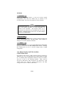
Figure 5 Add/Modify/Delete Users Dialog Box
Help
Choose the Help button to access the Help function. (Help is also
available by pressing the F1 key.)
Add User
Enter the new user in the New Username text box. When a new user
name is entered (typed) in this text box the Add button appears, taking
the place of the Save and Delete buttons.
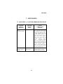
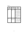
User Access Level
The access levels are "System Administrator,"
Administrator," "General Maintenance," and "User."
"Console
–
System Administrator – this level has access to all system
functions.
–
Console Administrator – this level has access to system
monitoring functions (Monitor System on CEC/IMC
Manager menu bar) and console configuration functions
(Console Configuration from the Configure System menu).
–
General Maintenance – this access level is currently not
supported. Selecting this access level will result in the same
access level as "User."
–
User – this level has access only to system monitoring
functions (Monitor System on CEC/IMC Manager menu bar).
3-6
LBI-39224
User Password
Select (no password required) or unselect (password required) the No
Password check box as required for the new user. If selected, no
further action is required. If unselected, enter the password in the New
Password text box, then re-enter the password in the Verify New
Password text box.
Add
Choose the Add button to add and save the new user account. This
button appears, taking the place of the Save and Delete buttons, when
a new user name is entered (typed) in the New Username text box.
When the Add action is complete the Save and Delete buttons will
reappear, taking the place of this button.
Save
Choose the Save button to save any changes to user account
configurations to the CEC/IMC Manager hard disk.
Delete
Choose the Delete button to delete the selected user account.
Close
Choose the Close button to exit this dialog box and return to the main
menu. If any changes have been made and not saved, you will be
prompted (Write Changes to Disk?) to save and exit (Yes), exit
without saving (No), or cancel the Close command and remain in the
dialog box (Cancel).
3.2.2 Modify Accounts
This option can be used to change user accounts or delete an account.
Only users with a system administrator access level may perform most
of these changes.
Help
Choose the Help button to access the Help function. (Help is also
available by pressing the F1 key.)
OK
Choose the OK button to save any new settings, activate those settings,
and exit the current dialog box.
3-7
LBI-39224
Cancel
Choose the Cancel button to immediately exit the current dialog box
without saving or activating any new settings.
Login As New User
Selected users may be able to login to the CEC/IMC Manager program
as a new (different) user, this "new" user must be a currently existing
user in the system. This option is performed from the Login dialog box
(Login As New User menu selection). Enter the new user name in the
User Name text box, enter the password for that user name in the
Password text box, and then choose the OK button to login under the
new user name.
Change Password
This option is used to change the password of an existing account. This
option is performed in the Set Password dialog box
(Change Password menu selection). Users that do not have a system
administrator access level may change only their own password.
System administrators may change any user account password.
Change Access Level
System administrators can use this option to change the access level of
a given user account.
This option is performed from the
Add/Modify/Delete Users dialog box (Modify User). Select the
account to be changed from the Current Users drop-down list box,
select the new access level from the User Level drop-down list box,
then choose the Save button to save and activate the change.
Delete Account
System administrators can use this option to delete user accounts. This
option is performed from the Add/Modify/Delete Users dialog box
(Modify User). Select the account to be deleted from the Current Users
drop-down list box, choose the Delete button to delete the account.
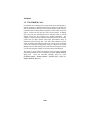
3.3 CEC/IMC MANAGER FONT SELECTION
The CEC/IMC Manager Graphical User Interface (GUI) can be
executed on the Network Management platform, which maintains a set
of fonts different from the CEC/IMC Manager PC fonts. Therefore, the
CEC/IMC Manager has a font selection dialog box; this font selection is
saved to disk by User Name. In some instances a particular font
selection that works fine at one platform may not work properly at
3-8
LBI-39224
another platform when the user logs in; in such instances a user may
need to have accounts at each platform under different user names with
a font selection for that particular platform. Because there is variation
between platforms font selection may be somewhat of a "trial-anderror" process to determine the best font combinations.
See
APPENDIX D - FONT SELECTABLE DIALOG BOXES for a list of
dialog boxes that are affected by the user selected fonts.
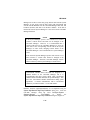
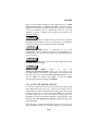
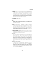
CEC/IMC Manager font selection is done in the Font dialog box. From
the CEC/IMC Manager main menu bar select Configure System /
CEC/IMC Manager Configuration / Font Selection to display the
Font dialog box.
Figure 6 Font Selection Dialog Box
Help
Choose the Help button to access the Help function. (Help is also
available by pressing the F1 key.)
Select the desired/required Font, Font Style, and Size from their
respective list boxes. As mentioned previously, because of the
variation between platforms, font selection may be somewhat of a "trialand-error" process to determine the best font combinations.
Cancel
Choose the Cancel button to exit the Font dialog box without saving
or activating any new settings.
OK
Choose the OK button to save any new settings, activate those settings,
and exit the Font dialog box.
3-9
LBI-39224
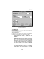
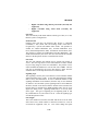
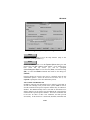
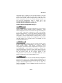
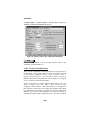
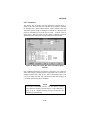
3.4 INITIAL CEC/IMC MANAGER AND MOM
CONTROLLER BOARD CONFIGURATION
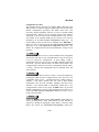
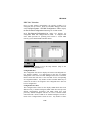
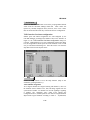
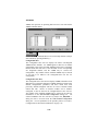
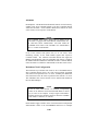
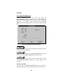
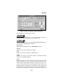
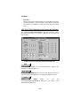
The CEC/IMC Manager Configuration dialog box, shown in Figure
7, is the configuration point for several CEC/IMC Manager and
CEC/IMC MOM Controller Board-related parameters. From the
CEC/IMC Manager menu bar select Configure System /
CEC/IMC Manager Configuration / Hardware (see Figure 3) to
display the CEC/IMC Manager Configuration dialog box. These
parameters include selecting one of the PC serial COM ports, setting
the serial baud rates for the CEC/IMC Manager-to-MOM Controller
Board and System Manager-to-MOM Controller Board serial links,
enabling/disabling data logging, and setting the datalog delete threshold
number.
Figure 7 CEC/IMC Manager Configuration Dialog Box
Help
Choose the Help button to access the Help function. (Help is also
available by pressing the F1 key.)
Cancel
Choose the Cancel button to immediately exit the
CEC/IMC Manager Configuration dialog box without saving or
activating any new settings.
PC COM Port Selection
Communication port selection for the PC serial port, the CEC/IMC
Manager ⇔ MOM Controller Board serial control data link, is
accomplished via the COM selections in the CEC/IMC Manager
Configuration dialog box. COM ports 1 thru 4 are supported. Select
3-10
LBI-39224
COM 1, COM 2, COM 3 or COM 4, as required using the respective
option button in the dialog box.
The selected serial port interrupt request line (IRQ) and base I/O port
address settings are established from the Microsoft Windows NT
Control Panel program settings. Typically, no IRQ or address changes
are ever required. However, if using non-standard serial port hardware,
changes may be necessary. If using non-standard serial port hardware,
consult the hardware manufacture's documentation for specific IRQ and
base I/O address details.
CEC/IMC Manager-MOM Baud Rate
Baud rate selection for the CEC/IMC Manager ⇔ MOM Controller
Board serial link is accomplished using the CEC/IMC Manager BAUD
Rate drop-down list box. In this list box baud rates of 9600 and 19.2k
baud are available, select 9600 or 19.2k baud as required. This setting
configures the previously chosen PC COM port for the selected rate.
Since the MOM Controller Board port used for CEC/IMC Manager
interfacing is auto-baud sensing, a baud rate change at the MOM
Controller Board is not necessary when a change is made in this list
box.
System Manager-MOM Baud Rate
The MOM Controller Board port used for interfacing with the System
Manager computer is configurable for 9600 or 19.2k baud using the
System Manager BAUD Rate drop-down list box. Unlike the
CEC/IMC Manager ⇔ MOM Controller Board setting, this setting
must match the setting at the System Manager before MOM Controller
Board ⇔ System Manager communication can occur, the System
Manager is not equipped with an auto-baud serial port. Refer to your
particular System Manager LBI for System Manager baud rate
configuration information. Select 9600 or 19.2k baud as required from
the drop-down list box.
Data Logging Of GSC Traffic
Once each day at midnight (00:00), the CEC/IMC Manager creates a
new datalog file and it names the file in accordance with the date. For
example, a datalog file created on July 2, 1996 will be named
07_02_96.DLG. This data can be viewed using the on-line
Calls Translation and GSC Monitor functions (available by selecting
Monitor System on the CEC/IMC Manager menu bar) described in
Chapter 4, SYSTEM MONITORING, or the CALLS.EXE and
3-11
LBI-39224
GSCMOM.EXE off-line programs as described in Chapter 5, OFFLINE DIAGNOSTIC FUNCTIONS.
If data logging is desired, select the Enable Datalog check box. With
this feature enabled the CEC/IMC Manager will log GSC traffic such as
channel assignments and drops.
The datalog delete threshold feature automatically deletes old datalog
files which are stored on the CEC/IMC Manager's hard disk drive. A
stored datalog file that is older than the number of days in the Datalog
Delete Threshold will be deleted at midnight. This prevents hard disk
drive "disk full" errors. Datalog files will also be deleted if the Datalog
Delete Threshold number is reduced. For example, if the previous
number was "8" (8 days) and the number is reduced to "5" (5 days) in
the CEC/IMC Manager Configuration dialog box, the three datalog
files that are more than 5 days old will be deleted from the hard disk
drive at midnight. The range for the Datalog Delete Threshold number
is 1 to 50. The value selected here should be at least equal to the
number of days between back-ups of the datalog files such that they are
saved before the CEC/IMC Manager automatically deletes them from
the hard disk drive. ERROR.DLG and WARN.DLG files are not
affected by the Datalog Delete Threshold setting.
OK
Choose the OK button to save any new settings, activate those settings,
and exit the CEC/IMC Manager Configuration dialog box.
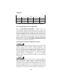
3.5 SYSTEM TIME AND DATE
This function is used to select the source of system time and date. This
time and date is broadcast throughout the entire CEC/IMC for time
synchronization.
This function is performed from the
Configure System Clock Synchronization dialog box. From the
CEC/IMC Manager menu bar select Configure System /
System Options
/
System Clock
to
display
the
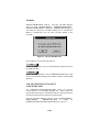
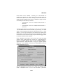
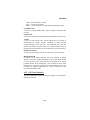
Configure System Clock Synchronization dialog box, Figure 9.
3-12
LBI-39224
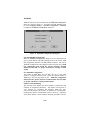
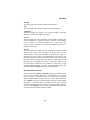
Figure 8 System Options Menu
Figure 9 Configure System Clock Synchronization Dialog Box
Help
Choose the Help button to access the Help function. (Help is also
available by pressing the F1 key.)
Current Time and Date
The system's current time and date is displayed in this field, the time is
in a 24-hour format (11:00:00 PM would be 23:00:00).
3-13
LBI-39224
Output CEC/IMC Manager Time to CEC/IMC
Select (enable) this check box to cause the CEC/IMC Manager time to
update the CEC/IMC time. The default is "selected"—"Output
CEC/IMC Manager Time to CEC/IMC." Unselect (disable) to force
the CEC/IMC to run on its own internal clock. This box should be
selected (enabled) if using the NETCLOCK/2 option. This box must be
unselected (disabled) if using the System Manager as the time source.
Source of CEC/IMC Manager Date and Time
This field defaults to "Internal." With the default setting, the CEC/IMC
Manager (MOM PC) time will be maintained by the PC internal
battery-backed clock.
The CEC/IMC can also receive its time from the System Manager.
Select the "System Manager" option button to enable CEC/IMC time
updates based on the System Manager time. If this option is selected,
the Output CEC/IMC Manager Time to CEC/IMC option must be
unselected (disabled).
If the Netclock/2 option is installed, select the "Netclock" option
button. See WWVB TIME STANDARD CONFIGURATION on page
3-199 for more information on Netclock installation and operation.
Read Disk
Choose the Read Disk button to display the current system time
configuration from the CEC/IMC Manager hard disk.
Save
Choose the Save button to save any changes to the system time
configuration to the CEC/IMC Manager hard disk.
Close
Choose the Close button to exit this dialog box and return to the main
menu. If any changes have been made and not saved, you will be
prompted (Write Changes to Disk?) to save and exit (Yes), exit
without saving (No), or cancel the Close command and remain in the
dialog box (Cancel).
3.6 SYSTEM MANAGER DATABASE UPLOADS
The CEC/IMC uses data from the System Manager Unit and Group
databases to control routing of all wide area (multisite) calls. These
databases must be setup correctly at the System Manager before the
System Manager data is transferred to the CEC/IMC. The CEC/IMC
3-14
LBI-39224
Manager user is able to select unit, group, and site data from the System
Manager; or unit, group, and site data, along with conventional and
console unit ID databases from the CEC/IMC Manager hard disk, and
broadcast (transfer) this data to all interface modules. If the data is
transferred from the System Manager it is also stored on the CEC/IMC
Manager hard disk.
NOTE
If the System Manager operates with version 4.0 (or earlier)
software, console aliases and LIDs can be changed at the
CEC/IMC Manager. However, it is recommended that a
console LID stored at the CEC/IMC Manager be given the
same alias as the corresponding console LID at the System
Manager; in other words, changing console aliases at the
CEC/IMC Manager is not recommended if a System Manager
exists.
If the network's System Manager operates with version 5.0 (or
later) software, a console alias cannot be changed at the
CEC/IMC Manager. Therefore, CEC/IMC Manager console
aliases will always match System Manager console aliases.
NOTE
Conventional Channel aliases and LIDs are assigned to a
channel number at the CEC/IMC Manager, but it is
recommended that these entries match valid conventional
channel aliases and LIDs defined at the System Manager. This
will ease conventional channel identification during patch
operations. A console communicates with a conventional
channel by its channel number—not its LID number.
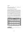
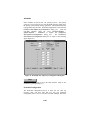
Database transfers (uploads/downloads) are accomplished using the
System Mgr/Network Mgr Entity Database dialog box. From the
CEC/IMC Manager menu bar select Configure System /
Systems Options
/
File Transfer
to
display
the
System Mgr/Network Mgr Entity Database dialog box, Figure 10.
3-15
LBI-39224
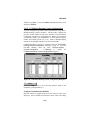
Figure 10 System Mgr/Network Mgr Entity Database Dialog Box
Help
Choose the Help button to access the Help function. (Help is also
available by pressing the F1 key.)
Close
Choose the Close button to exit the System Mgr/
Network Mgr Entity Database dialog box and return to the CEC/IMC
Manager main window.
Current Status
The Current Status box provides information about the transfer
currently in progress or the most recent transfer. Selected transfer type,
whether "In Progress," "Complete," or "Failed," and number of Records
involved are displayed.
Request
The Request box allows the user to select between Full or Partial file
transfers. Transfers from the System Manager may be either full or
partial for all entities except Site. Only full transfers are supported
from the CEC/IMC Manager.
Pending/History Status
The fields under Pending/History Stats give information about the
upload, received at the CEC/IMC Manager, selected from the drop3-16
LBI-39224
down list box: whether it was full or partial, status, and number of
records in the database file that were updated.
Entity
The Entity box allows the user to select the entity database to be
updated. Transfers from the System Manager may be Unit, Group, or
Site. Transfers from the CEC/IMC Manager may be any of the
available options.
3.6.1 Transfer From System Manager
If a "Transfer From System Manager" is desired, all data will be
requested from the System Manager. Select either Full or Partial
transfer using the option buttons in the Request box. Select unit, group,
or site database to transfer using the option buttons in the Entity box,
keep in mind that a partial site transfer is not allowed.
Request from SysMgr
Choose the Request from SysMgr button to initiate a System
Manager based database transfer.
Send to CEC/IMC
Choose the Send to CEC/IMC button to broadcast the currently
requested database transfer to the CEC/IMC interface modules.
The Current Status box shows the type of transfer selected, indicates
that the transfer is "In Progress," and displays a running count of
records transferred until transfer is complete, at which time the total
number of records updated will be displayed.
For a "Transfer From System Manager" request it is not necessary for
the previous transfer to complete before requesting a different transfer.
You may request a unit transfer immediately followed by group and site
transfers, or any combination thereof, a popup screen will tell you that
your request has been queued. It is also not necessary to remain in the
screen from which the transfer was requested while the databases are
being transferred. You may initiate the transfer and then proceed to
another screen to perform some other action.
Close
Choose the Close button to exit the System Mgr/
Network Mgr Entity Database dialog box, if no other database
transfers are desired, and return to the CEC/IMC Manager main
window.
3-17
LBI-39224
3.6.2 Transfer From CEC/IMC Manager
If a "Transfer From CEC/IMC Manager" is desired, all upload data will
originate from the CEC/IMC Manager's hard disk. This is data stored
from a previous System Manager upload. In addition, conventional and
console unit ID databases can be uploaded from the CEC/IMC
Manager.
The conventional database is built using the
Conv. Interface Adapter Configuration menu option from the VMIM
menu (CEC/IMC Configuration). The console database is built using
the
Console User Profile
menu
option
from
the
Console Configuration menu. A transfer will be aborted if a full
transfer from the System Manager begins while the CEC/IMC Manager
based transfer is in progress, or if a database file read error occurs. If a
CEC/IMC Manager based transfer is in progress and a partial System
Manager transfer occurs, the CEC/IMC Manager based transfer request
will be "failed," CEC/IMC Manager requests are not queued. This is to
allow other GUI clients an opportunity to submit requests.
In the Request box select Full for full upload, unlike System Manager
transfers which allow partial transfer requests for units and groups, only
full transfers are supported for CEC/IMC Manager based transfers.
Select the desired database to be updated from any of the available
options using the option buttons in the Entity box.
Read Disk
Choose the Read Disk button to request (read) the selected database
files transferred from the CEC/IMC Manager hard disk.
Send to CEC/IMC
Choose the Send to CEC/IMC button to broadcast the currently
requested database transfer to the CEC/IMC interface modules.
The Current Status box will show the type of transfer selected, indicate
that the transfer is "In Progress," and display a running count of records
transferred until transfer is complete, at which time the total number of
records updated will be displayed.
It is not necessary to remain in the screen from which the transfer was
requested while the databases are being transferred. You may initiate
the transfer and then proceed to another screen to perform some other
action.
3-18
LBI-39224
Close
Close
Choose
the
button
to
exit
the
System Mgr/Network Mgr Entity Database dialog box, if no other
database transfers are desired, and return to the CEC/IMC Manager
main window.
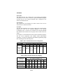
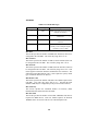
3.7 TDM BUS CONFIGURATION
The CEC/IMC Digital Audio Switch is equipped with a Time Division
Multiplexed (TDM) network which transfers audio signals, modem data
signals, and user data signals throughout the switch. TDM network bus
and time slot configurations are performed from the CEC/IMC
Manager. These configurations set the CEC/IMC for 4- or 8-TDM bus
operation and allocate a TDM time slot for each input channel. TDM
time slot allocation procedures are described in the next section.
TDM bus configuration must match the specific hardware installed
within the CEC/IMC, early CEC/IMC Audio Boards utilized only four
(4) buses and all later Audio Boards utilize eight (8) buses. A
CEC/IMC with 4-bus Audio Boards will not route signals correctly if
the CEC/IMC is configured for eight buses. A CEC/IMC with 8-bus
Audio Boards but configured for 4-bus operation will operate correctly;
however, approximately one-half of the total TDM time slots will not
be available. The 8-bus Audio Boards include 19D903302P1 Rev. F
(and later) boards with 344A3561G3 (and later) firmware, and all
19D903302P3 boards. All T1/E1 Interface Cards are 8-bus capable.
NOTE
The MOM Controller Board default TDM bus setting is eight.
This default number is established within the MOM firmware.
If the MOM Controller's non-volatile RAM (NOVRAM) is
cleared, the CEC/IMC will return to 8-bus operation without
intervention from the CEC/IMC Manager. If 4-bus operation
is required, the TDM bus configuration must be reset to the
required number– 4 –after a MOM Controller Board
NOVRAM clear. Refer to the diagnostic procedures within
LBI-38938 for instructions on clearing Controller Board
NOVRAM.
3-19
LBI-39224
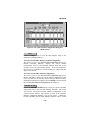
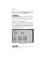
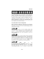
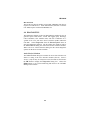
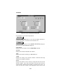
TDM bus allocations are performed from the TDM Bus Configuration
dialog box, shown in Figure 11. From the CEC/IMC Manager menu
bar select Configure System / CEC/IMC Configuration / TDM Bus
to display the TDM Bus Configuration dialog box.
Figure 11 TDM Bus Configuration Dialog Box
Current TDM Bus Configuration
When the TDM Bus Configuration dialog box is first opened this field
may be blank until the CEC/IMC Manager receives the current TDM
Bus configuration from the CEC/IMC MOM Controller. The current
TDM Bus configuration is then displayed in this read-only field. TDM
bus configuration must match the specific hardware installed
within the CEC/IMC for proper and effective routing of audio
signals.
New TDM Bus Configuration
The number of TDM Buses the CEC/IMC will use to route audio
signals is configured from this field. Select the required number of
TDM Buses from the drop-down list box. TDM bus configuration
must match the specific hardware installed within the CEC/IMC
for proper and effective routing of audio signals.
Number of Slots Remaining
This read-only field displays the current number of TDM time slots
available for assignment (allocation). This number will decrease as
"site" channels are configured and allocated TDM time slots,
conversely this number will increase as channels are "unconfigured."
Changing the number of TDM Buses (above) will have a significant
effect on the number of slots available; increasing the number of buses
3-20
LBI-39224
will greatly increase the number of slots available, and decreasing the
number of buses will greatly decrease the number of slots available.
Help
Choose the Help button to access the Help function. (Help is also
available by pressing the F1 key.)
Cancel
Choose the Cancel button to exit the TDM Bus Configuration dialog
box without saving or activating any new settings.
OK
Choose the OK button to save any new settings, activate those settings,
exit the TDM Bus Configuration dialog box and return to the
CEC/IMC Manager main window.
3.8 SITE-TYPE INTERFACE MODULE CHANNEL
CONFIGURATION
This section describes channel-related configurations applicable to
"site"-type (MIM, NIM, VMIM, PIM and CTIM) interface modules
that are performed at the CEC/IMC Manager. NIM, VMIM, PIM and
CTIM site-type interface modules do not actually interface with
EDACS trunked sites; however, each interface module is assigned a
unique site assignment number (1 thru 32). Each interface module type
will be discussed separately because, although similar, they do have
slight differences and this is an important step in CEC/IMC switch
setup. Also, some modules may be equipped with the new T1/E1
Interface Card (currently only MIMs, NIMs, and PIMs may be so
equipped). Configuration of both Audio Board-equipped interface
modules and T1/E1 Interface Card-equipped interface modules will be
covered in those cases.
3-21
LBI-39224
NOTE
In most cases, the term "site" in this program does not refer to
an EDACS trunked site or any other type of radio system. It
refers instead to a site-type interface module within the
CEC/IMC or StarGate Controller Digital Audio Switch. The
number that follows is the interface module's site assignment
number. This number corresponds to and matches the site
assignment number set by the 5-bit DIP switch setting on the
interface module's Controller Board.
Prior to actual channel configuration the interface module to be
configured must be selected. From the CEC/IMC Manager menu bar
select Configure System / CEC/IMC Configuration / the desired
interface module (MIM, NIM, VMIM, PIM or CTIM) from the
CEC/IMC Configuration menu, shown in Figure 12. When an
interface module is selected from the CEC/IMC Configuration menu
the Site Channel Configuration List dialog box for that module is
displayed.
3-22
LBI-39224
Figure 12 CEC/IMC Configuration Menu
3.8.1 MIM Channel Configuration
Interfacing between the CEC/IMC and an EDACS trunked site is
accomplished with a MASTR™ II/III Interface Module (MIM). The
MIM consists of a Controller Board and up to eight Audio or T1/E1
Interface Boards. An optional standby Controller Board may be used
with an EDACS trunked site for redundant downlink operation.
MIM "Site" Selection
Prior to actual channel configuration the interface module to be
configured must be selected.
Select MIM from the
CEC/IMC Configuration menu. When an interface module is selected
from this menu the Site Channel Configuration List dialog box for
that module appears, Figure 13.
3-23
LBI-39224
Figure 13 Site Channel Configuration List Dialog Box
(MIM Shown)
Each Site Channel Configuration List dialog box displays the
configurable "sites" and configured/active "sites." An active "site"
represents an active Controller Board control data link. For example, in
the case of a MIM this represents an operating link between an EDACS
trunked site and the MIM Controller Board.
Help
Choose the Help button to access the Help function. (Help is also
available by pressing the F1 key.)
Configurable Sites:
The Configurable Sites list box displays all inactive unconfigured sitetype interface modules. If a MIM appears in this box, no channel
configuration exists at the CEC/IMC Manager and no active Controller
Board control data link exists at the CEC/IMC for the corresponding
site assignment number. Any number of these available MIMs may be
selected at one time to be added to the Configured/Active list box for
configuration.
Configured/Active Sites:
The Configured/Active Sites list box displays "sites" which have been
added but not yet channel-configured, "sites" which have had previous
channel configurations performed, and "sites" which have been
previously channel-configured and have an active Controller Board
control data link. Before a site-type interface module can be channelconfigured, it must be listed in the Configured/Active Sites list box.
Any number of the available "sites" in this list may be selected at one
time for modification in the Site Channel Configuration dialog box.
3-24
LBI-39224
All selected MIMs in this list will also be included in the "Save As…"
dialog box that is accessed from the Site Channel Configuration
dialog box or T1/E1 Digital Site Configuration dialog box. The
particular state is indicated by a prefix as defined in the following table.
Table 1 Configured/Active Sites Prefix Definitions
PREFIX
MEANING
**
The "site" has been added for
configuration but is not active and no
channel configurations have been
performed or saved.
A
The control data link is active and
configuration data exists at the
CEC/IMC (default values if nothing
else) but not necessarily at the
CEC/IMC Manager.
C
Channel configurations have been
performed and saved for the "site"
but the control data link is not active.
C/A
Channel configurations have been
performed and saved for the "site"
and the control data link is active.
Those site-type interface modules followed by "(TEC)" are T1/E1
Interface Card equipped and are configured as described in T1/E1
Interface Card-Equipped MIM Configuration, on page 3-35.
Add
Choose the Add button to move a selected site from the Configurable
Sites list box and "add" it to the Configured/Active Sites list box, where
it can now be selected for configuration. If upon adding a site, a
configuration data file exists on the CEC/IMC Manager's hard disk
drive from a previous add and delete, the site will be added to the
Configured/Active Sites list box with its configuration data file (with a
** prefix). This previous configuration may be modified, saved, and
sent as needed.
Modify
Choose the Modify button to display the Audio Interface Type dialog
box, select either Audio Board or T1/E1 Interface Board as required by
selecting the appropriate option button. Selecting Audio Board will
activate the Site Channel Configuration dialog box, selecting T1/E1
3-25
LBI-39224
Interface Board will activate the T1/E1 Digital Site Configuration
dialog box. These options are discussed in detail in subsequent
sections.
Delete
Choose the Delete button to remove ("delete") a selected configured or
unconfigured site from the Configured/Active Sites list box to the
Configurable Sites list box. Configured-and-active sites (C/A prefix)
cannot be "deleted." This delete function does not remove "site"
channel configuration files from the CEC/IMC Manager's hard disk
drive. Therefore, if the "deleted" site is subsequently added back to the
Configured/Active Sites list box using the Add button, the previous
channel configuration is not lost (this configuration data must be resaved in the Site Channel Configuration dialog box before it can be
resent to the CEC/IMC).
Close
Choose the Close button to exit the dialog box and return to the main
menu. Any "**" (unconfigured and unsaved) sites appearing in the
Configured/Active Sites list box will be removed and returned to the
Configurable Sites list box.
Audio Interface Type Selection
For those site-type interface modules that may be equipped with either
an Audio Board or T1/E1 Interface Card (currently only MIMs, NIMs,
and PIMs may be so equipped), the audio interface type must be
selected before channel configuration can continue.
In the Site Channel Configuration List dialog box select the desired
site-type interface modules to configure from the Configured/Active
Sites list, or add the desired modules from the Configurable Sites list, if
not already listed, as described earlier. Choose Modify to display the
Audio Interface Type dialog box, select either the Audio Board option
button or the T1/E1 Interface Board option button, then choose OK to
continue. Choose the Close button to exit the Audio Interface Type
dialog box and return to the Site Channel Configuration List dialog
box.
Audio Board option
If
Audio
Board
was
selected
(Figure
14),
the
Site Channel Configuration dialog box will be displayed. Continue
with channel configuration as described in "Audio Board-Equipped
Channel Configuration."
3-26
LBI-39224
Figure 14 Audio Interface Type Dialog Box
(Audio Board selected)
T1/E1 Interface option
If T1/E1 Interface Card was selected (Figure 15), a new set of option
buttons will appear.
T1 is a digital transmission facility operating at 1.544 Mbps (million
bits per second) in a full-duplex, time-division-multiplexing mode. T1
is the first level or primary rate within a digital transmission and
switching hierarchy defined by AT&T called a T Carrier System. North
America has adopted the T Carrier System as a standard for digital
transmission of voice, data, and images. Time-division multiplexing
permits the derivation of logical channels within the serial bit stream.
The CEC/IMC T1/E1 Interface will allocate twenty-four 64 kbps T1
channels.
E1 digital transmission is very similar to T1. The major difference is in
the bit rate. E1 is a digital transmission facility operating at 2.048
Mbps. The difference in bit rate allows for different channel allocation
schemes. The CEC/IMC T1/E1 Interface will allocate thirty-one 64
kbps E1 channels. E1 transmission has been adopted as the digital
transmission standard in European countries.
T1/E1 selection is performed at the CEC/IMC Manager on a CEC/IMC
wide basis. Changing the line type will cause the entire T1/E1 database
to be reset (lost) for all T1/E1 "sites." T1 or E1 selection is dependent
upon the line service coming into the CEC/IMC (T1 and E1 lines are
physically different), and as mentioned above, depends upon what part
of the world you are in. Selecting T1 or E1 should only be required
when the system is first configured, after that the current system
configuration will be indicated when the Audio Interface Type dialog
box appears on your screen and changing line type is not necessary or
desired.
Choose
the
OK
button
and
the
3-27
LBI-39224
T1/E1 Digital Site Configuration dialog box will appear. Continue
with channel configuration as described in "T1/E1 Interface Card
Equipped Configuration."
Figure 15 Audio Interface Type Dialog Box
(T1/E1 Interface Card selected)
Audio Board-Equipped MIM Channel Configuration
This section describes configurations for channels within Audio Boardequipped site-type interface modules. All channel parameters are
configured from the Site Channel Configuration dialog box, Figure
16.
Only those "sites" which were selected in the
Site Channel Configuration List dialog box are available for channel
configuration. The selected sites are displayed in a list box at the top
center of the dialog box.
3-28
LBI-39224
Figure 16 Site Audio Channel Configuration Dialog Box
(MIM Shown)
Help
Choose the Help button to access the Help function. (Help is also
available by pressing the F1 key.)
View Current CEC/IMC Manager Channel Configuration
The upper list box in the Site Channel Configuration dialog box,
labeled "CEC/IMC Manager," displays the current channel
configurations stored on the CEC/IMC Manager hard disk for the
currently selected site-type interface module. As the edit fields above
this list box are modified for a selected channel, the changes will also
appear in this list box.
View Current CEC/IMC Channel Configuration
The lower list box in the Site Channel Configuration dialog box,
labeled "CEC/IMC," displays the current channel configurations stored
at the CEC/IMC for the currently selected site-type interface module.
Information within this box updates only after Send is performed from
the preceding Site Channel Configuration List dialog box.
CEC/IMC to Disk
Choose the CEC/IMC to Disk button to write the current CEC/IMC
configuration data to the CEC/IMC Manager hard disk. This action
will overwrite the current CEC/IMC Manager configuration for the
selected interface module. This function is useful if the CEC/IMC
Manager configuration database is lost for any reason. A difference
between CEC/IMC and CEC/IMC Manager databases will be evident
3-29
LBI-39224
by comparing the CEC/IMC Manager and CEC/IMC list boxes in the
Site Channel Configuration dialog box. Ensure that the CEC/IMC
configuration is correct, then choose the CEC/IMC to Disk button to
restore the CEC/IMC Manager configuration database (for the selected
interface module).
Channel Selection
Select a channel (1 thru 32) for configuration from the CEC/IMC
Manager list box, only one channel may be selected at a time. The
selected channel and its configuration data will be displayed in the edit
fields above the CEC/IMC Manager list box.
Input Signal Level (dBm)
This setting establishes the signal level in dBm (600-ohm impedance;
0 dBm = 1 milliwatt) applied to the selected channel's line input. Enter
(type) the required value in the text box. The setting should be equal to
the voice peak (test tone) level applied to the channel's line input.
Voice peak levels are +10 dBm greater than average voice levels.
Valid range is -25.0 dBm to 12.0 dBm, adjustable in 0.5 dBm
increments. The program automatically rounds-off non-0.5 dBm
fractional entries to the nearest 0.5 dBm point. Input Signal Level
default = 0 dBm.
NOTE
If Automatic Level Control (ALC) is disabled for the selected
channel, subtract 1.5 dBm from the required Input Signal
Level setting. For example, if the required input signal level is
-10 dBm, enter -11.5 dBm. ALC is disabled by setting the
ALC text box to "NO."
LBI-38938 contains a line level adjustment overview section which
contains general information and general recommendations for both
input and output level settings.
Output Signal Level (dBm)
This setting establishes the signal level in dBm (600-ohm impedance;
0 dBm = 1 milliwatt) sent out by the selected channel's line output. The
setting specifies the voice peak (test tone) level sent out by the channel.
The valid range is -25.0 dBm to 13.0 dBm, generally in 0.5 dBm
increments, select the required value from the drop-down list box.
Output Signal Level default = 0 dBm.
3-30
LBI-39224
Channel Signaling
This drop-down list box specifies the type of channel signaling sent out
by the selected channel for control of external equipment such as an
EDACS trunked site or co-located mux equipment. Valid settings are
"NONE" for no signaling, "TONE" for tone control signaling, "E&M"
for M-lead control signaling, and "BOTH" for both tone and M-lead
control signaling. Channel Signaling default = "NONE."
EDACS trunked sites require specialized tone control signaling for
transmit keying. For a MIM, all utilized channels require either a
"TONE" or a "BOTH" setting. Specific tone level settings are
accomplished via the "Secure Tone" text box described in the following
section.
Secure Tone
This setting establishes the level of the 2175 Hz secure tone and
transmit hold tone sent out by the Audio Board's channel prior to and
during a switch-to-site transmission. The set level is only utilized if
Channel Signaling is "TONE" or "BOTH." Valid range is -10 dBm to
11 dBm, which specifies the secure tone level. The 2175 Hz transmit
hold tone is always sent out 30 dBm below the secure tone setting.
NOTE
The secure tone and transmit hold tone are set on a per Audio
Board basis. For example, setting channel 2 equal to 5 dBm
will simultaneously set channels 1, 3 and 4 equal to 5 dBm.
Unlike conventional base stations, EDACS trunked site base stations do
not require a function tone for proper transmit keying. Therefore, the
presence of a function tone is not guaranteed and no longer specified
for MIMs.
Bus/Slot Equipped
All utilized channels within an interface module must be allocated a
time slot on the CEC/IMC TDM network. Allocate a time slot to the
selected channel by setting Bus/Slot Equipped to "YES." A channel
will not route audio correctly if is not allocated a time slot. Set all
unused channels to "NO," the default setting.
3-31
LBI-39224
For example, if the currently selected site-type interface module is a
20-channel MIM with five (5) Audio Boards addressed 1 thru 5,
Bus/Slots Equipped for channels 1 thru 20 must be "YES."
NOTE
In earlier CEC/IMC firmware/software releases, slot
allocations could only be made contiguously starting with
channel one (1). In some systems this produced slot allocation
inefficiencies, i.e., some slots had to be allocated but were
never used. CEC/IMC software/firmware release 5.0 (and
later) provides non-contiguous slot allocations. In this release,
only those slots actually required need be allocated. For
example, channels 1 and 4 can be allocated slots without
allocating slots to channels 2 and 3.
Notch Filter
CAUTION
DO NOT enable the 2175 Hz Notch Filter for any channel if
the respective Audio Board part number is 19D903302P1 (any
revision).
Each Audio Board channel is equipped with a 2175 Hz notch filter
circuit which when enabled eliminates destructive interference of the
channel's 2175 Hz transmit keying tone. In some cases, this destructive
interference or "talk down" can cause incorrect (early) trunked site
channel drops. To enable the selected channel's notch filter, enter
"YES" in the Notch Filter text box. Notch Filter default = "NO"
(disabled).
ALC
CAUTION
DO NOT enable ALC for any channel if the respective Audio
Board part number is 19D903302P1 (any revision).
Automatic Level Control (ALC) provides compensation for signal level
variances in a channel line input signal. As required, enable ALC for
3-32
LBI-39224
the selected channel by entering "YES" in the ALC text box or disable
it by entering "NO."
Save and Send MIM Audio Board Configurations
When channel configuration of the selected interface module is
complete, the Site Channel Configuration dialog box changes must be
sent to the CEC/IMC before the changes will take effect. This
reprograms the MIM Controller Boards. However, it is important to
save the new configuration prior to sending it to the CEC/IMC because
a send will send the last configuration that was saved to disk; saving
first ensures that the actual CEC/IMC channel configuration will be the
same as the channel configuration stored on the CEC/IMC Manager
hard disk. To save and send configurations, action is required first in
the Site Channel Configuration dialog box and then in the
Site Channel Configuration List dialog box.
Site Channel Configuration dialog box
Save
Choose the Save button to perform an immediate save of the currently
selected site-type interface module's channel configuration. Other
"sites" displayed in the list box located at the top of the dialog box are
not saved. This channel configuration is saved on the CEC/IMC
Manager's hard disk drive. Any previous channel configuration for the
"site," if present, is erased and replaced with the current channel
configuration. If the CEC/IMC Manager is running remotely or as a
part of the EDACS Network Manager, this configuration is saved on the
CEC/IMC Manager server, typically local to the CEC/IMC; it is not
saved at the remote location.
Save As...
Choose the Save As… button to allow the currently selected site-type
interface module channel configurations to be saved as a different sitetype interface module. It is provided to speed configurations when
similar MIM configurations are required. Upon choosing Save As… a
small dialog box, Figure 17, will appear which allows entry of a new
MIM number. Select the desired MIM number from one of the choices
in the drop-down list box, the choices listed are the selected MIMs in
the Configured/Active Sites list box. Like Save, Save As… stores
channel configuration on the CEC/IMC Manager server.
3-33
LBI-39224
Figure 17 "Save As…" Dialog Box
For example, if "Site 8" is the currently selected site-type interface
module and "Site 12" requires similar configuration settings, this button
may be used to save the "Site 8" configuration as "Site 12" (save to
"12"). The new "site" may then be changed later, as required, by
selecting it from the selection list box, changing the configuration as
required, and then choosing Save.
Close
Choose the Close button to exit the Site Channel Configuration
dialog box and enter the Site Channel Configuration List dialog box.
If any changes have been made and not saved, you will be prompted
(Write Changes to Disk?) to save and exit (Yes), exit without saving
(No), or cancel the Close command and remain in the dialog box
(Cancel).
Site Channel Configuration List dialog box
Send
Choose the Send button to send the site channel configuration data to
the respective interface module. This procedure must be performed
before the interface module will operate with the new configuration.
Only configured and configured-and-active (C and C/A prefixes)
configurations may be sent. All configuration data is sent to the MOM
Controller Board; the Audio configuration is sent directly out from
there to the respective interface module Controller Board. A "Send to
Site Successful" message will be received to confirm that the data was
received by the interface module Controller Board.
Bus Slot
configuration data is compared to the current configuration at the
CEC/IMC Manager; if different, it is sent to the MOM Controller
Board (if not, no further action is taken by the system) and when the
3-34
LBI-39224
MOM Controller Board receives this new data it will send an
acknowledgment message back to the CEC/IMC Manager, which will
then display the confirmation box: "Do you want to activate TDM Bus
Slots? OK - will cause all CTRL boards to reset." Choose OK to
activate TDM Bus Slots (resetting Controller Boards) with the new Bus
Slot configuration data, choose Cancel to not activate TDM Bus Slots
with the new Bus Slot configuration data (keeping the previous
configuration) and return to the Site Channel Configuration List
dialog box.
Close
Choose the Close button to exit the Site Channel Configuration List
dialog box and return to the CEC/IMC Manager main window. Any
"**" (unconfigured and unsaved) sites appearing in the
Configured/Active Sites list box will be removed and returned to the
Configurable Sites list box.
T1/E1 Interface Card-Equipped MIM Configuration
This section describes configuration for channels of T1/E1 Interface
Card-equipped interface modules (currently only MIMs, NIMs, and
PIMs are so equipped). Channel configurations are performed from the
T1/E1 Digital Site Configuration dialog box (Figure 18) and from the
T1/E1 Interface Card Auto-configuration dialog box (Figure 19). As
was the case with Audio Board-equipped site-type interface modules,
only
those
"sites"
which
were
selected
in
the
Site Channel Configuration List dialog box are available for channel
configuration.
NOTE
Like the CEC/IMC Audio Board, each T1/E1 Interface Card
within a CEC/IMC interface module must have a unique board
address setting. This address is 1 - 8 (addresses 2 - 8 are
currently not available).
3-35
LBI-39224
NOTE
T1/E1 selection is performed at the CEC/IMC Manager on a
CEC/IMC wide basis. Changing the Line Type will cause the
complete T1/E1 database to be reset (lost). The Line Type
shown as the "default" when the Audio Interface Type dialog
box appears is how the system is configured and Line Type
should not be changed.
The T1/E1 Interface Card provides a built-in T1 or E1 port for
CEC/IMC interface modules. This port allows direct interfacing to
T1/E1 microwave, fiber-optic, or leased lines facilities. Consequently,
co-located T1/E1 multiplexing (mux) equipment at the CEC/IMC is
eliminated when the T1/E1 Interface Card is employed. CEC/IMC
Audio Boards are also eliminated within the particular interface
module. Within each of these interface modules, one or more T1/E1
Interface Cards replace all Audio Boards. The T1/E1 Interface Card
furnishes twenty-four full-duplex T1 channels in T1 mode and thirtyone full-duplex E1 channels in E1 mode. In addition to its T1/E1 port,
the T1/E1 Interface Card also contains eight subrate ports which,
depending upon board configuration, can provide modem-less data
links over spare T1/E1 channels to either internal or external devices.
Some, all, or none of these ports can be utilized depending on board
configuration. Five of the subrate ports support synchronous or
asynchronous data links and the remaining three are synchronous-only
ports.
T1/E1 Digital Site Configuration
Networked Systems Considerations
Any system nodes that are connected using T1/E1 Interfaces must
remain frequency locked at all times. The T1/E1 Interface design
allows for total network synchronization by offering the following
CEC/IMC Configuration options. Each of these options are selectable
by configuration of both the Clock Boards and the T1/E1 Interface
Cards.
3-36
LBI-39224
1.
Master - Redundant Clock Circuits generated by the Clock
Board in a FREE RUN mode. This allows any CEC/IMC to
become the master source of Network timing. All nodes
connected to this CEC/IMC will be in the slave mode. This
mode is established by setting the Clock Board DIP switches
to "Master" mode and all the T1/E1 Interface Cards' Slave
Clock option to "NONE."
2.
T1/E1 Slave - Redundant Clock Circuits generated by the
Clock Board synchronized to 1 (or 2 with redundancy) T1/E1
Interface into the CEC/IMC. The CEC/IMC can be slaved to
an external node that is connected through a T1/E1 link, and
no additional timing source is needed. Timing from the T1/E1
line is passed to the Clock Board from the T1/E1 Interface
Cards through a redundant set of synchronization clocks
named Slave A and Slave B. Each T1/E1 Interface Card can
provide Slave A, B or A&B. This mode is established by
setting the Clock Board DIP switches to "Slave to 8kHz" and 1
T1/E1 Interface Card Slave Clock option set to "SLAVE A,"
with another set to "SLAVE B" for redundancy, or 1 T1/E1
Interface Card set to "SLAVE A&B" for no redundancy.
3.
Slave to external 1.544 MHz - Redundant Clock Circuits
generated by the Clock Board synchronized to 1 (or 2 with
redundancy) external clock source. Any CEC/IMC can be
synchronized to the timing output from a T1/E1 multiplexer,
microwave radio, fiber network, etc. Connect the external
timing source to both Clock Boards in the CEC/IMC for
redundancy. This mode is established by setting the Clock
Board DIP switches to "Slave to Ext. 1544 kHz" and all T1/E1
Interface Cards' Slave Clock option to "NONE."
4.
Slave to external 2.048 MHz (E1 mode only) - Redundant
Clock Circuits generated by the Clock Board synchronized to
1 (or 2 with redundancy) external clock source. Any
CEC/IMC can be synchronized to the timing output from a
T1/E1 multiplexer, microwave radio, fiber network, etc.
Connect the external timing source to both Clock Boards in the
CEC/IMC for redundancy. This mode is established by setting
the Clock Board DIP switches to "Slave to 2048 kHz" and all
T1/E1 Interface Cards' Slave Clock option to "NONE."
The following configuration guidelines must be followed for network
synchronization:
3-37
LBI-39224
1.
One node in the system must be the MASTER source of
network timing. The CEC/IMC will support a primary and
redundant (or alternate) MASTER sources of timing as
indicated above.
2.
A MASTER node can be defined as a site, a Jessica, a T1/E1
link, or a CEC/IMC.
3.
All leased T1/E1 facilities from the telephone company are
frequency locked by the phone company. If there are any
phone company T1/E1 connections, one of the connections
must be the MASTER source of timing. Any other phone
company connections may be the redundant MASTER source
of timing. Phone company T1/E1 connections include leased
lines for sites/multinode and T1/E1 connections through an
MD110 (Jessica).
4.
Any nodes using analog interfaces (including analog
connections from an MD110 to the phone company) may be
disregarded for synchronization purposes.
5.
If a node is not a MASTER timing node, it must be slaved to
the T1/E1 link going towards the MASTER node.
3-38
LBI-39224
Figure 18 T1/E1 Digital Site Configuration Dialog Box
(T1 Line Type Selected)
Help
Choose the Help button to access the Help function. (Help is also
available by pressing the F1 key.)
Analog or Digital Voice
In addition to T1 or E1 selection, T1/E1 Interface Card configuration
includes selecting one of three primary board operating modes:
–
Analog/modem mode ("Analog or Digital Voice using
Modems")
In the analog/modem mode, the T1/E1 Interface Card transfers
PCM-encoded signals between the CEC/IMC TDM network
and the T1/E1 line. PCM-encoded signals transferred by this
mode include analog (clear) voice, modem-encoded digital
voice, and/or modem-encoded data signals. In this mode each
site channel is assigned to a T1/E1 channel. In addition, this
mode allows use of the T1/E1 Interface Card subrate ports if
T1/E1 channels are available after site channel assignments.
Two CEC/IMC TDM bus slots coincide to one full duplex
T1/E1 Channel. This is exactly analogous to a CEC/IMC
Audio Board channel where two TDM bus slots coincide to
3-39
LBI-39224
one full duplex 4-wire 600-ohm audio channel provided by the
Audio Board. The T1/E1 Interface Card extracts a signal from
one bus slot and sends it out on a T1/E1 channel.
Accordingly, signals received on this same T1/E1 channel are
applied to a different CEC/IMC TDM bus slot.
–
Digital voice/data using subrate ports mode (currently not
supported)
–
Digital voice/data using T1/E1 mode (currently not
supported)
Line Type
This is a read-only field which indicates which type of line (T1 or E1)
that the system is configured for.
Frame Format
Framing deals with how the digitized data stream is configured
(formatted), a data stream with one framing format would not be
recognized by a system with another frame format. The possible T1
formats are 4-Frame Multiframe (F4), 12-Frame Multiframe (F12,
D3/4), Extended Superframe (ESF), and Remote Switch Mode (F72).
The possible E1 formats are Doubleframe and CRC Multiframe. The
format is determined by the service line used. Select from the available
choices in the drop-down list box to match the line format.
Line Code
The line code indicates the method used to encode long strings of
zeroes. The receiving end of a T1/E1 link would not be able to remain
in sync if long strings of zeroes were transmitted. The possible T1 line
codes are B8ZS and AMI w/ZCS. The E1 line code is HDB3. The line
code also is determined by the service line utilized. Select from the
available choices in the drop-down list box to match the line.
Signaling Type
This signaling is used by the T1/E1 Interface Card to transmit channel
status information (busy or idle). T1 uses bits robbed from the channel
data to convey this information. E1 uses a dedicated channel to send
signaling information for all channels; therefore, only 30 user channels
are allowed. In a CEC/IMC system, signaling must be set for MIM site
interfaces, and the T1/E1 muxes and base stations at the associated site
location must be configured for E&M Signaling unless the site is all
digital (no analog voice). Signaling should not be set for any other
device types. The types of signaling are No Signaling (both T1 and
3-40
LBI-39224
E1), Robbed Bit for T1, and CAS-CC for E1. Select the signaling type
from the drop-down list box.
Line Length
This is the distance between the CEC/IMC and the device at the other
end of the T1 line, which could be a microwave transceiver, a mux in
co-located site equipment, CSU, etc. Line effects change the signal
slightly, and the changes become more pronounced the further the
signal travels down the line. The outgoing original signal is modified
based upon line length so that the signal arriving at the destination
closely resembles an ideal signal. Select the line length from the dropdown list box for T1 applications. E1 applications do not support
selectable line lengths.
Set Site Channel Disbursement
The Set Site Channel Disbursement field sets the number of channels
assigned to the indicated T1/E1 Interface Card. Enter the number of
channels in the text box (1 - 24 for T1 or 1 - 31 for E1).
Select Slave Clock Mode
Selecting the Slave Clock Mode is part of a higher level system design,
as mentioned earlier. Any system nodes that are connected using T1/E1
Interfaces must remain frequency locked at all times. The T1/E1
Interface design allows for total network synchronization through
different CEC/IMC configuration options. A detailed discussion of the
higher level system configuration is beyond the scope of this topic;
however, for a more detailed discussion refer to T1/E1 Interface
Release Notes (350A1909) and CEC/IMC Digital Audio Switch
Installation, Set-up, and Troubleshooting (LBI-38938). Select the
required clock mode from the drop-down list box.
View
Choose the View button to display the T1/E1 Interface Card Autoconfiguration dialog box, which shows the T1/E1 channels and subrate
port configurations.
Read Disk
Choose the Read Disk button to view the currently stored
configuration on the CEC/IMC Manager hard disk. This normally
should be the same as the actual configuration at the CEC/IMC.
Read MSC
Choose the Read MSC button to view the actual configuration at the
CEC/IMC (stored in the interface module's NOVRAM). This normally
3-41
LBI-39224
should be the same as the configuration stored on the CEC/IMC
Manager hard disk. If the CEC/IMC Manager hard disk data was
cleared or reset to undesired values, Read MSC followed by Save
will restore the CEC/IMC Manager hard disk configuration.
Set Defaults
Choose the Set Defaults button to select the pre-programmed default
values from the CEC/IMC Manager hard disk. These values will
replace any currently displayed values; however, these "new" values
must be saved and sent before they will become the new configuration.
T1/E1 Interface Card Auto-configuration
Subrate ports and channel assignments are auto-configured by the
CEC/IMC Manager according to the number of free T1/E1 channels. In
Figure 19, the T1/E1 Interface Card Auto-configuration dialog box
is shown. Although there are no user configurable fields in this dialog
box, the assignment of subrate ports and T1/E1 channels can be viewed
on a per card basis in this dialog box. Select the card to view from the
drop-down list box in the top left corner.
Figure 19 T1/E1 Interface Card Auto-configuration dialog box
(T1 Line Type Selected)
Help
Choose the Help button to access the Help function. (Help is also
available by pressing the F1 key.)
3-42
LBI-39224
T1/E1 Channel Assignment
T1/E1 logical channels are assigned starting with channel 1, these are
the channels used to transmit voice, data, and image signals from one
system node to another. E1 channel 16 is used for signaling if signaling
is enabled. (See "Signaling Type" under T1/E1 Digital Site
Configuration above.) Subrate ports for user data are assigned channels
adjacent/after logical channels according to the table below.
Asynchronous (async) ports, up to 5, are assigned first and then
synchronous (sync) ports are assigned.
Table 2 Subrate Port Assignments for Analog/Modem Mode
Free Channels (Per Card)
Subrate Port Auto-configuration*
0
no subrate ports available
1
port 1 = async
ports 2 - 8 = not available
2
port 1 = async
ports 2 - 5 = sync
ports 6 - 8 = not available
3
ports 1 & 2 = async
ports 3 - 5 = sync
ports 6 - 8 = not available
4
ports 1 - 3 = async
ports 4 & 5 = not available
ports 6 - 8 = sync
5
ports 1 - 4 = async
port 5 = not available
ports 6 - 8 = sync
>5
ports 1 - 5 = async
ports 6 - 8 = sync
* "sync" = subrate port set for synchronous operation
"async" = subrate port set for asynchronous operation
Subrate Port Channel Assignment
Asynchronous subrate ports require an individual channel assignment
for each port, however, up to five synchronous subrate ports can be
packed in one T1/E1 channel using DS0B subrate multiplexing. Based
on hardware considerations at the T1/E1 Interface Card, sync ports 1 - 5
and 6 - 8 would be packed in pre-assigned DS0B "sub-channels" as
shown below.
3-43
LBI-39224
← DS0 →
subchannel 1
subchannel 2
subchannel 3
subchannel 4
subchannel 5
1
2
3
4
5
6
7
8
Table 3 Synchronous Subrate Port Packing Arrangement
Save And Send MIM T1/E1 Configurations
Any
T1/E1 Digital Site Configuration
dialog
box
or
T1/E1 Interface Card Auto-configuration dialog box changes must
be sent before the changes will come into effect at the CEC/IMC. This
reprograms the MIM Controller Boards and T1/E1 Interface Cards.
The new configurations must be saved before sent to the CEC/IMC, if
sending is attempted before saving a "Site data must be saved to disk
prior to send" message box will appear. Save and send may be
performed either from the T1/E1 Interface Card Auto-configuration
dialog box only, or from the Site Channel Configuration List dialog
box, similar to Audio Board save and send.
T1/E1 Interface Card Auto-configuration dialog box
Save
Choose the Save button to perform an immediate save of the currently
selected site-type interface module's channel configuration. The
channel configuration is saved on the CEC/IMC Manager's hard disk
drive. Any previous channel configuration for the "site," if present, is
erased and replaced with the current channel configuration. If the
CEC/IMC Manager is running remotely or as a part of the EDACS
Network Manager, this configuration is saved on the CEC/IMC
Manager server, typically local to the CEC/IMC; it is not saved at the
remote location.
Send
Choose the Send button to send the T1/E1 site channel configuration
data to the respective interface module. This procedure must be
performed before the interface module will operate with the new
configuration. Only configured and configured-and-active (C and C/A
prefixes) configurations may be sent. All configuration data is sent to
the MOM Controller Board; the T1/E1 configuration is sent directly out
from there to the respective interface module Controller Board. A
3-44
LBI-39224
"Send to Site Successful" message will be received to confirm that the
data was received by the interface module Controller Board. Bus Slot
configuration data is based on the channel assignment in the Set Site
Channel Disbursement field (one bus slot per channel assigned) and is
compared to the current configuration at the CEC/IMC Manager; if
different, it is sent to the MOM Controller Board (if not, no further
action is taken by the system) and when the MOM Controller Board
receives this new data it will send an acknowledgment message back to
the CEC/IMC Manager, which will then display the confirmation box:
"Do you want to activate TDM Bus Slots? OK - will cause all CTRL
boards to reset." Choose OK to activate TDM Bus Slots (resetting
Controller Boards) with the new Bus Slot configuration data, choose
Cancel to not activate TDM Bus Slots with the new Bus Slot
configuration data (keeping the previous configuration) and return to
the T1/E1 Interface Card Auto-configuration dialog box.
T1/E1 Digital Site Configuration dialog box
Save
Choose the Save button to perform an immediate save of the currently
selected site-type interface module's channel configuration. This
channel configuration is saved on the CEC/IMC Manager's hard disk
drive. Any previous channel configuration for the MIM, if present, is
erased and replaced with the current channel configuration. If the
CEC/IMC Manager is running remotely or as a part of the EDACS
Network Manager, this configuration is saved on the CEC/IMC
Manager local to the CEC/IMC; it is not saved at the remote location.
Save As...
Choose the Save As… button to allow the currently selected site-type
interface module channel configurations to be saved as a different sitetype interface module. It is provided to speed configurations when
similar MIM configurations are required. Upon choosing Save As… a
small dialog box, similar to Figure 17 on page 3-34, will appear which
allows selection of a new MIM number. Select the desired MIM
number from one of the choices in the displayed list, the choices
displayed are the selected MIMs in the Configured/Active Sites list box.
Like Save, Save As… stores channel configuration on the CEC/IMC
Manager server.
Close
Choose the Close button to exit the T1/E1 Digital Site Configuration
dialog box. If any changes have been made and not saved, a prompt
3-45
LBI-39224
will appear to warn of the unsaved changes and the user will be given
the opportunity to save and exit (Save) or exit without saving the
changes (Cancel).
Site Channel Configuration List dialog box
Send
Choose the Send button to send the T1/E1 site channel configuration
data to the respective interface module. This procedure must be
performed before the interface module will operate with the new
configuration. Only configured and configured-and-active (C and C/A
prefixes) configurations may be sent. All configuration data is sent to
the MOM Controller Board; the T1/E1 configuration is sent directly out
from there to the respective interface module Controller Board. A
"Send to Site Successful" message will be received to confirm that the
data was received by the interface module Controller Board. Bus Slot
configuration data is based on the channel assignment in the Set Site
Channel Disbursement field (one bus slot per channel assigned) and is
compared to the current configuration at the CEC/IMC Manager; if
different, it is sent to the MOM Controller Board (if not, no further
action is taken by the system) and when the MOM Controller Board
receives this new data it will send an acknowledgment message back to
the CEC/IMC Manager, which will then display the confirmation box:
"Do you want to activate TDM Bus Slots? OK - will cause all CTRL
boards to reset." Choose OK to activate TDM Bus Slots (resetting
Controller Boards) with the new Bus Slot configuration data, choose
Cancel to not activate TDM Bus Slots with the new Bus Slot
configuration data (keeping the previous configuration) and return to
the Site Channel Configuration List dialog box.
Close
Choose the Close button to exit the Site Channel Configuration List
dialog box and return to the CEC/IMC Manager main window. Any
"**" (unconfigured and unsaved) sites appearing in the
Configured/Active Sites list box will be removed and returned to the
Configurable Sites list box.
3.8.2 NIM Channel Configuration
Two or more IMC networks can be linked together for "distributed
multisite" communications using a Network Interface Module (NIM) at
each IMC switch. NIM links are communication gateways that support
a limited amount of communication traffic between network switches.
3-46
LBI-39224
Each NIM is assigned a unique site assignment number (1 thru 32)
within the CEC/IMC. This number corresponds to and matches the site
assignment number set via the 5-bit DIP switch setting on the interface
module’s Controller Board. A NIM may be either Audio Board
equipped or T1/E1 Interface Card equipped, both situations will be
discussed.
Multinode Configuration
NOTE
For this discussion the term "multinode" will be synonymous
with distributed multisite network involving multiple IMC
networks connected together by Network Interface Modules
(NIMs).
Some additional configuration considerations are required when linking
two or more IMC networks together for multinode operation. The NIM
control data link between the IMC networks must be established prior
to NIM channel audio configuration. The NIM on each end of the link
must be manually set to equal baud rates; this is performed in the
StarGate / Remote CEC / NIM Configuration dialog box as
described in DISTRIBUTED MULTISITE / STARGATE
CONFIGURATION, beginning on page 3-141. Those nodes (IMC
networks) that will make-up the multinode system must have their
Group and Unit Databases downloaded from the System Manager. This
is accomplished by downloading the System Manager Group and Unit
Databases from the System Manager as discussed in SYSTEM
MANAGER DATABASE UPLOADS, beginning on page 3-14, and
may have already been accomplished during the course of normal
CEC/IMC configuration. At the very least the Group and Unit
Database download should be verified as being complete.
The CEC/IMC ID ("switch assignment number") must be set at the
MOM Controller Board before distributed multisite (multinode)
communications will operate correctly. The CEC/IMC firmware will
automatically display a CEC/IMC ID number even if one is not set at
the MOM; therefore, a displayed CEC/IMC ID does not guarantee that
the number has been set. Ensure that this switch assignment number
has been set using the DIP switches on the MOM Controller Board as
specified in the Distributed Multisite/StarGate Configuration section of
3-47
LBI-39224
LBI-38938, CEC/IMC Digital Audio Switch Installation, Set-up, and
Troubleshooting.
NIM "Site" Selection
Prior to actual channel configuration, the interface module to be
configured must be selected. From the CEC/IMC Manager menu bar
select Configure System / CEC/IMC Configuration / NIM to display
the Site Channel Configuration List dialog box for that module.
Figure 20 NIM Site Channel Configuration List Dialog Box
Each Site Channel Configuration List dialog box displays the
configurable NIMs and configured/active NIMs. A configured and
active NIM represents an active operating control link between the NIM
Controller Boards in two networked CEC/IMC switches.
Help
Choose the Help command button to access the Help function. (Help is
also available by pressing the F1 key.)
Configurable Sites:
The Configurable Sites list box displays all inactive unconfigured sitetype interface modules. If a NIM appears in this box, no channel
configuration exists at the CEC/IMC Manager and no active Controller
Board control data link exists at the CEC/IMC for the corresponding
site assignment number, and the NIM may be selected for
configuration. Any number of these available NIMs may be selected at
one time to be added to the Configured/Active list box for
configuration.
3-48
LBI-39224
Configured/Active Sites:
The Configured/Active Sites list box displays NIMs which have been
added but not yet channel-configured, NIMs which have had previous
channel configurations performed, and NIMs which have been
previously channel-configured and have an active Controller Board
control data link. Before a site-type interface module can be channelconfigured, it must be listed in the Configured/Active Sites list box.
Any number of the available NIMs may be selected at one time for
modification in the Site Channel Configuration dialog box. All
selected NIMs in this list will also be included in the "Save As…"
dialog box that is accessed from the Site Channel Configuration
dialog box or the T1/E1 Digital Site Configuration dialog box. See
Table 1 for Configured/Active Sites Prefix Definitions on page 3-25 if
necessary.
Add
Choose the Add button to move a selected NIM from the Configurable
Sites list box and "add" it to the Configured/Active Sites list box where
it can be selected for configuration. If upon adding a NIM, a
configuration data file exists on the CEC/IMC Manager's hard disk
drive from a previous add and delete, the NIM will be added to the
Configured/Active Sites list box with its configuration data file (with a
** prefix). This previous configuration may be modified, saved, and
sent as needed.
Delete
Choose the Delete button to remove ("delete") a selected configured or
unconfigured NIM from the Configured/Active Sites list box to the
Configurable Sites list box. Configured-and-active NIMs cannot be
"deleted." This delete function does not remove NIM channel
configuration files from the CEC/IMC Manager's hard disk drive.
Therefore, if the deleted NIM is subsequently added back to the
Configured/Active Sites list box using the Add button, the previous
channel configuration is not lost (this configuration data must be resaved in the Site Channel Configuration dialog box before it can be
resent to the CEC/IMC).
Modify
Choose the Modify button and the Audio Interface Type dialog box
will be presented, select either Audio Board or T1/E1 Interface as
required by clicking the appropriate option button. Selecting Audio
Board will activate the Site Channel Configuration dialog box,
3-49
LBI-39224
selecting
T1/E1
Interface
will
T1/E1 Digital Site Configuration dialog box.
discussed in detail in subsequent sections.
activate
the
These options are
Audio Board Equipped NIM Configuration
This section describes configurations for channels within Audio Boardequipped NIMs. All channel parameters are configured from the (NIM)
Site Channel Configuration dialog box, Figure 21. Only those NIMs
which were selected in the Site Channel Configuration List dialog
box are available for channel configuration. Select the desired NIMs to
configure from the Configured/Active Sites list, or add the desired
NIMs from the Configurable Sites list, if not already listed, as described
earlier. Choose Modify and the Audio Interface Type dialog box,
Figure 14 on page 3-27, will be displayed, select the Audio Board
option, then choose OK to display the Site Channel Configuration
dialog box, Figure 21. The selected NIMs are displayed in a list box at
the top center of the dialog box. Audio Board-equipped NIMs require
less settings than Audio Board-equipped MIM, VMIM and PIM
interface modules.
Figure 21 NIM Site Channel Configuration Dialog Box
Help
Choose the Help button to access the Help function. (Help is also
available by pressing the F1 key.)
3-50
LBI-39224
View Current CEC/IMC Manager Channel Configuration
The upper list box in the Site Channel Configuration dialog box,
labeled "CEC/IMC Manager," displays the current channel
configurations stored on the CEC/IMC Manager hard disk for the
currently selected NIM. As the edit fields above this list box are
modified for a selected channel, the changes will appear also in this list
box for the selected channel.
View Current CEC/IMC Channel Configuration
The lower list box in the Site Channel Configuration dialog box,
labeled "CEC/IMC," displays the current channel configurations stored
at the CEC/IMC for the currently selected NIM. Information within
this box updates only after Send is performed from the preceding
Site Channel Configuration List dialog box.
CEC/IMC to Disk
Choose the CEC/IMC to Disk button to write the current CEC/IMC
configuration data to the CEC/IMC Manager hard disk. This action
will overwrite the current CEC/IMC Manager configuration for the
selected interface module. This function is useful if the CEC/IMC
Manager configuration database is lost for any reason. A difference
between CEC/IMC and CEC/IMC Manager databases will be evident
by comparing the CEC/IMC Manager and CEC/IMC list boxes in the
Site Channel Configuration dialog box. Ensure that the CEC/IMC
configuration is correct, then choose the CEC/IMC to Disk button to
restore the CEC/IMC Manager configuration database (for the selected
interface module).
Channel Selection
Select a channel (1 thru 32) for configuration from the CEC/IMC
Manager channel list box, only one channel may be selected at a time.
The selected channel and its configuration data will be displayed in the
edit fields above the CEC/IMC Manager list box.
Input Signal Level (dBm)
This setting establishes the signal level in dBm (600-ohm impedance;
0 dBm = 1 milliwatt) applied to the selected channel's line input. Type
the required value in the text box. The setting should be equal to the
voice peak (test tone) level applied to the channel's line input. Voice
peak levels are +10 dBm greater than average voice levels. Valid range
is -25.0 dBm to 12.0 dBm, adjustable in 0.5 dBm increments. The
program automatically rounds-off non-0.5 dBm fractional entries to the
nearest 0.5 dBm point. Input Signal Level default = 0 dBm.
3-51
LBI-39224
NOTE
If Automatic Level Control (ALC) is disabled for the selected
channel, subtract 1.5 dBm from the required Input Signal
Level setting. For example, if the required input signal level is
-10 dBm, enter -11.5 dBm. ALC is disabled by setting the
ALC text box to "NO."
LBI-38938 contains a line level adjustment overview section which
contains general information and general recommendations for both
input and output level settings.
Output Signal Level (dBm)
This setting establishes the signal level in dBm (600-ohm impedance;
0 dBm = 1 milliwatt) sent out by the selected channel's line output. The
setting specifies the voice peak (test tone) level sent out by the channel.
Valid range is -25.0 dBm to 13.0 dBm, in 0.5 dBm increments. Select
the required value from the drop-down list box. Output Signal Level
default = 0 dBm.
Bus/Slot Equipped
All utilized channels within an interface module must be allocated a
time slot on the CEC/IMC TDM network. Allocate a time slot to the
selected channel by setting Bus/Slot Equipped to "YES." A channel
will not route audio correctly if is not allocated a time slot. Set all
unused channels to "NO" (default setting).
Channel Equipped
This parameter is unique to NIMs, and must be enabled for each
installed distributed multisite audio channel. Enter "YES" in the text
box to enable those channels, enter "NO" for all unused channels.
ALC
CAUTION
DO NOT enable ALC for any channel if the respective Audio
Board part number is 19D903302P1 (any revision).
Automatic Level Control (ALC) provides compensation for signal level
variances in a channel line input signal. As required, enable ALC for
the selected channel by entering "YES" in the ALC text box or disable
it by entering "NO."
3-52
LBI-39224
Save and Send NIM Audio Board Configurations
When channel configuration of the selected NIM is complete, the
Site Channel Configuration dialog box changes must be sent to the
CEC/IMC before the changes will take effect. This reprograms the
NIM Controller Boards. However, it is important to save the new
configuration prior to sending it to the CEC/IMC because a send will
send the last configuration saved to disk; saving first ensures that the
actual CEC/IMC channel configuration will be the same as the channel
configuration stored on the CEC/IMC Manager hard disk. To save and
send
configurations,
action
is
required
first
in
the
Site Channel Configuration dialog box and then in the
Site Channel Configuration List dialog box.
Site Channel Configuration dialog box
Save
Choose the Save button to perform an immediate save of the currently
selected site-type interface module's channel configuration. Other
"sites" displayed in the list box located at the top of the dialog box are
not saved. This channel configuration is saved on the CEC/IMC
Manager hard disk drive. Any previous channel configuration for the
"site," if present, is erased and replaced with the current channel
configuration. If the CEC/IMC Manager is running remotely or as a
part of the EDACS Network Manager, this configuration is saved on the
CEC/IMC Manager server, typically local to the CEC/IMC; it is not
saved at the remote location.
Save As...
Choose the Save As… button to allow the currently selected NIM
channel configurations to be saved as a different NIM. It is provided to
speed configurations when similar configurations are required. Upon
choosing Save As… a small dialog box (See Figure 17) will appear
which allows selection of a new NIM number. Select the desired NIM
number from one of the choices in the drop-down list box, the choices
listed are the selected NIMs in the Configured/Active Sites list box.
Like Save, Save As… stores channel configuration on the CEC/IMC
Manager server.
For example, if "Site 3" is the currently selected site-type interface
module and "Site 12" requires similar configuration settings, this button
may be used to save the "Site 3" configuration as "Site 12" (save to
"12"). The new "site" may then be changed later, as required, by
3-53
LBI-39224
selecting it via the selection list box, changing the configuration as
required, and then choosing Save.
Close
Choose the Close button to exit this dialog box and return to the
Site Channel Configuration List dialog box. If any changes have
been made and not saved, you will be prompted
(Write Changes to Disk?) to save and exit (Yes), exit without saving
(No), or cancel the Close command and remain in the dialog box
(Cancel).
Site Channel Configuration List dialog box
Send
Choose the Send button to send the site channel configuration data to
the respective interface module. This procedure must be performed
before the interface module will operate with the new configuration.
Only configured and configured-and-active (C and C/A prefixes)
configurations may be sent. All configuration data is sent to the MOM
Controller Board; the Audio configuration is sent directly out from
there to the respective interface module Controller Board. A "Send to
Site Successful" message will be received to confirm that the data was
received by the interface module Controller Board.
Bus Slot
configuration data is compared to the current configuration at the
CEC/IMC Manager; if different, it is sent to the MOM Controller
Board (if not, no further action is taken by the system) and when the
MOM Controller Board receives this new data it will send an
acknowledgment message back to the CEC/IMC Manager, which will
then display the confirmation box: "Do you want to activate TDM Bus
Slots? OK - will cause all CTRL boards to reset." Choose OK to
activate TDM Bus Slots (resetting Controller Boards) with the new Bus
Slot configuration data, choose Cancel to not activate TDM Bus Slots
with the new Bus Slot configuration data (keeping the previous
configuration) and return to the Site Channel Configuration List
dialog box.
Close
Choose the Close button to exit the Site Channel Configuration List
dialog box and return to the CEC/IMC Manager main window. Any
"**" (unconfigured and unsaved) NIMs appearing in the
Configured/Active Sites list box will be removed and returned to the
Configurable Sites list box.
3-54
LBI-39224
T1/E1 Equipped NIM Configuration
This section describes configuration for channels of T1/E1 Interface
Card-equipped NIMs. Channel configurations are performed from the
T1/E1 Digital Site Configuration dialog box, shown in Figure 18 on
page 3-39, and from the T1/E1 Interface Card Auto-configuration
dialog box, Figure 19 on page 3-42. As was the case with Audio
Board-equipped NIMs, only those NIMs selected in the
Site Channel Configuration List dialog box are available for channel
configuration.
NOTE
Like the CEC/IMC Audio Board, each T1/E1 Interface Card
within a CEC/IMC interface module must have a unique board
address setting. This address is 1 - 8 (addresses 2 - 8 are
currently not available).
NOTE
T1/E1 selection is performed at the CEC/IMC Manager on a
CEC/IMC wide basis. Changing the Line Type will cause the
complete T1/E1 database to be reset (lost). The Line Type
shown as the "default" when the Audio Interface Type dialog
box appears is how the system is configured and Line Type
should not be changed.
The T1/E1 Interface Card provides a built-in T1 or E1 port for
CEC/IMC interface modules. This port allows direct interfacing to
T1/E1 microwave, fiber-optic, or leased lines facilities. Consequently,
co-located T1/E1 multiplexing (mux) equipment at the CEC/IMC is
eliminated when the T1/E1 Interface Card is employed. CEC/IMC
Audio Boards are also eliminated within the particular interface
module. Within each of these interface modules, one or more T1/E1
Interface Cards replace all Audio Boards. The T1/E1 Interface Card
furnishes twenty-four full-duplex T1 channels in T1 mode and thirtyone full-duplex E1 channels in E1 mode. In addition to its T1/E1 port,
the T1/E1 Interface Card also contains eight subrate ports which,
3-55
LBI-39224
depending upon board configuration, can provide modem-less data
links over spare T1/E1 channels to either internal or external devices.
Some, all, or none of these ports can be utilized depending on board
configuration. Five of the subrate ports support synchronous or
asynchronous data links and the remaining three are synchronous-only
ports.
T1/E1 Digital Site Configuration
Networked Systems Considerations
Any system nodes that are connected using T1/E1 Interfaces must
remain frequency locked at all times. The T1/E1 Interface design
allows for total network synchronization by offering the following
CEC/IMC Configuration options. Each of these options are selectable
by configuration of both the Clock Boards and the T1/E1 Interface
Cards.
1.
Master - Redundant Clock Circuits generated by the Clock
Board in a FREE RUN mode. This allows any CEC/IMC to
become the master source of Network timing. All nodes
connected to this CEC/IMC will be in the slave mode. This
mode is established by setting the Clock Board DIP switches
to "Master" mode and all the T1/E1 Interface Cards' Slave
Clock option to "NONE."
2.
T1/E1 Slave - Redundant Clock Circuits generated by the
Clock Board synchronized to 1 (or 2 with redundancy) T1/E1
Interface into the CEC/IMC. The CEC/IMC can be slaved to
an external node that is connected through a T1/E1 link, and
no additional timing source is needed. Timing from the T1/E1
line is passed to the Clock Board from the T1/E1 Interface
Cards through a redundant set of synchronization clocks
named Slave A and Slave B. Each T1/E1 Interface Card can
provide Slave A, B or A&B. This mode is established by
setting the Clock Board DIP switches to "Slave to 8kHz" and 1
T1/E1 Interface Card Slave Clock option set to "SLAVE A,"
with another set to "SLAVE B" for redundancy, or 1 T1/E1
Interface Card set to "SLAVE A&B" for no redundancy.
3-56
LBI-39224
3.
Slave to external 1.544 MHz - Redundant Clock Circuits
generated by the Clock Board synchronized to 1 (or 2 with
redundancy) external clock source. Any CEC/IMC can be
synchronized to the timing output from a T1/E1 multiplexer,
microwave radio, fiber network, etc. Connect the external
timing source to both Clock Boards in the CEC/IMC for
redundancy. This mode is established by setting the Clock
Board DIP switches to "Slave to Ext. 1544 kHz" and all T1/E1
Interface Cards' Slave Clock option to "NONE."
4.
Slave to external 2.048 MHz (E1 mode only) - Redundant
Clock Circuits generated by the Clock Board synchronized to
1 (or 2 with redundancy) external clock source. Any
CEC/IMC can be synchronized to the timing output from a
T1/E1 multiplexer, microwave radio, fiber network, etc.
Connect the external timing source to both Clock Boards in the
CEC/IMC for redundancy. This mode is established by setting
the Clock Board DIP switches to "Slave to 2048 kHz" and all
T1/E1 Interface Cards' Slave Clock option to "NONE."
The following configuration guidelines must be followed for network
synchronization:
1.
One node in the system must be the MASTER source of
network timing. The CEC/IMC will support a primary and
redundant (or alternate) MASTER sources of timing as
indicated above.
2.
A MASTER node can be defined as a site, a Jessica, a T1/E1
link, or a CEC/IMC.
3.
All leased T1/E1 facilities from the telephone company are
frequency locked by the phone company. If there are any
phone company T1/E1 connections, one of the connections
must be the MASTER source of timing. Any other phone
company connections may be the redundant MASTER source
of timing. Phone company T1/E1 connections include leased
lines for sites/multinode and T1/E1 connections through an
MD110 (Jessica).
4.
Any nodes using analog interfaces (including analog
connections from an MD110 to the phone company) may be
disregarded for synchronization purposes.
5.
If a node is not a MASTER timing node, it must be slaved to
the T1/E1 link going towards the MASTER node.
3-57
LBI-39224
Help
Choose the Help button to access the Help function. (Help is also
available by pressing the F1 key.)
Analog or Digital Voice
In addition to T1 or E1 selection, T1/E1 Interface Card configuration
includes selecting one of three primary board operating modes:
–
Analog/modem mode ("Analog or Digital Voice using
Modems")
In the analog/modem mode, the T1/E1 Interface Card transfers
PCM-encoded signals between the CEC/IMC TDM network
and the T1/E1 line. PCM-encoded signals transferred by this
mode include analog (clear) voice, modem-encoded digital
voice, and/or modem-encoded data signals. In this mode each
site channel is assigned to a T1/E1 channel. In addition, this
mode allows use of the T1/E1 Interface Card subrate ports if
T1/E1 channels are available after site channel assignments.
Two CEC/IMC TDM bus slots coincide to one full duplex
T1/E1 Channel. This is exactly analogous to a CEC/IMC
Audio Board channel where two TDM bus slots coincide to
one full duplex 4-wire 600-ohm audio channel provided by the
Audio Board. The T1/E1 Interface Card extracts a signal from
one bus slot and sends it out on a T1/E1 channel.
Accordingly, signals received on this same T1/E1 channel are
applied to a different CEC/IMC TDM bus slot.
3-58
LBI-39224
–
Digital voice/data using subrate ports mode (currently not
supported)
–
Digital voice/data using T1/E1 mode (currently not
supported)
Line Type
This is a read-only field which indicates which type of line (T1 or E1)
that the system is configured for.
Frame Format
Framing deals with how the digitized data stream is configured
(formatted), a data stream with one framing format would not be
recognized by a system with another frame format. The possible T1
formats are 4-Frame Multiframe (F4), 12-Frame Multiframe (F12,
D3/4), Extended Superframe (ESF), and Remote Switch Mode (F72).
The possible E1 formats are Doubleframe and CRC Multiframe. The
format is determined by the service line used. Select from the available
choices in the drop-down list box to match the line format.
Line Code
The line code indicates the method used to encode long strings of
zeroes. The receiving end of a T1/E1 link would not be able to remain
in sync if long strings of zeroes were transmitted. The possible T1 line
codes are B8ZS and AMI w/ZCS. The E1 line code is HDB3. The line
code also is determined by the service line utilized. Select from the
available choices in the drop-down list box to match the line.
Signaling Type
This signaling is used by the T1/E1 Interface Card to transmit channel
status information (busy or idle). T1 uses bits robbed from the channel
data to convey this information. E1 uses a dedicated channel to send
signaling information for all channels; therefore only 30 user channels
are allowed. In a CEC/IMC system, signaling must be set for MIM site
interfaces, and the T1/E1 muxes and base stations at the associated site
location must be configured for E&M Signaling unless the site is all
digital (no analog voice). Signaling should not be set for any other
device types. The types of signaling are No Signaling (both T1 and
E1), Robbed Bit for T1, and CAS-CC for E1. Select the signaling type
from the drop-down list box.
Line Length
This is the distance between the CEC/IMC and the device at the other
end of the T1 line, which could be a microwave transceiver, a mux in
co-located site equipment, CSU, etc. Line effects change the signal
3-59
LBI-39224
slightly, and the changes become more pronounced the further the
signal travels down the line. The outgoing original signal is modified
based upon line length so that the signal arriving at the destination
closely resembles an ideal signal. Select the line length from the dropdown list box for T1 applications. E1 applications do not support
selectable line lengths.
Set Site Channel Disbursement
The Set Site Channel Disbursement field sets the number of channels
assigned to the indicated T1/E1 Interface Card. Enter the number of
channels in the text box (1 - 24 for T1 or 1 - 31 for E1).
Select Slave Clock Mode
Selecting the Slave Clock Mode is part of a higher level system design,
as mentioned earlier. Any system nodes that are connected using T1/E1
Interfaces must remain frequency locked at all times. The T1/E1
Interface design allows for total network synchronization through
different CEC/IMC configuration options. A detailed discussion of the
higher level system configuration is beyond the scope of this topic;
however, for a more detailed discussion refer to T1/E1 Interface
Release Notes (350A1909) and CEC/IMC Digital Audio Switch
Installation, Set-up, and Troubleshooting (LBI-38938). Select the
required clock mode from the drop-down list box.
View
Choose the View button to display the T1/E1 Interface Card Autoconfiguration dialog box, which shows the T1/E1 channels and subrate
port configurations.
Read Disk
Choose the Read Disk button to view the currently stored
configuration on the CEC/IMC Manager hard disk. This normally
should be the same as the actual configuration at the CEC/IMC.
Read MSC
Choose the Read MSC button to view the actual configuration at the
CEC/IMC (stored in the interface module's NOVRAM). This normally
should be the same as the configuration stored on the CEC/IMC
Manager hard disk. If the CEC/IMC Manager hard disk data was
cleared or reset to undesired values, Read MSC followed by Save
will restore the CEC/IMC Manager hard disk configuration.
3-60
LBI-39224
Set Defaults
Choose the Set Defaults button to select the pre-programmed default
values from the CEC/IMC Manager hard disk. These values will
replace any currently displayed values; however, these "new" values
must be saved and sent before they will become the new configuration.
T1/E1 Interface Card Auto-configuration
Subrate ports and channel assignments are auto-configured by the
CEC/IMC Manager according to the number of free T1/E1 channels. In
Figure 19, the T1/E1 Interface Card Auto-configuration dialog box
is shown. Although there are no user configurable fields in this dialog
box, the assignment of subrate ports and T1/E1 channels can be viewed
on a per card basis in this dialog box. Select the card to view from the
drop-down list box in the top left corner.
Help
Choose the Help button to access the Help function. (Help is also
available by pressing the F1 key.)
T1/E1 Channel Assignment
T1/E1 logical channels are assigned starting with channel 1, these are
the channels used to transmit voice, data, and image signals from one
system node to another. E1 channel 16 is used for signaling if signaling
is enabled. (See "Signaling Type" under T1/E1 Digital Site
Configuration above.) Subrate ports for user data are assigned channels
adjacent/after logical channels according to Table 2 on page 3-43.
3-61
LBI-39224
Asynchronous (async) ports, up to 5, are assigned first and then
synchronous (sync) ports are assigned.
Save And Send NIM T1/E1 Configurations
Any
T1/E1 Digital Site Configuration
dialog
box
or
T1/E1 Interface Card Auto-configuration dialog box changes must
be sent before the changes will come into effect at the CEC/IMC. This
reprograms the NIM Controller Boards and T1/E1 Interface Cards. The
new configurations must be saved before sent to the CEC/IMC, if
sending is attempted before saving a "Site data must be saved to disk
prior to send" message box will appear. Save and send may be
performed either from the T1/E1 Interface Card Auto-configuration
dialog box only, or from the Site Channel Configuration List dialog
box, similar to Audio Board save and send.
T1/E1 Interface Card Auto-configuration dialog box
Save
Choose the Save button to perform an immediate save of the currently
selected site-type interface module's channel configuration. The
channel configuration is saved on the CEC/IMC Manager's hard disk
drive. Any previous channel configuration for the "site," if present, is
erased and replaced with the current channel configuration. If the
CEC/IMC Manager is running remotely or as a part of the EDACS
Network Manager, this configuration is saved on the CEC/IMC
Manager server, typically local to the CEC/IMC; it is not saved at the
remote location.
Send
Choose the Send button to send the T1/E1 site channel configuration
data to the respective interface module. This procedure must be
performed before the interface module will operate with the new
configuration. Only configured and configured-and-active (C and C/A
prefixes) configurations may be sent. All configuration data is sent to
the MOM Controller Board; the T1/E1 configuration is sent directly out
from there to the respective interface module Controller Board. A
"Send to Site Successful" message will be received to confirm that the
data was received by the interface module Controller Board. Bus Slot
configuration data is based on the channel assignment in the Set Site
Channel Disbursement field (one bus slot per channel assigned) and is
compared to the current configuration at the CEC/IMC Manager; if
different, it is sent to the MOM Controller Board (if not, no further
3-62
LBI-39224
action is taken by the system) and when the MOM Controller Board
receives this new data it will send an acknowledgment message back to
the CEC/IMC Manager, which will then display the confirmation box:
"Do you want to activate TDM Bus Slots? OK - will cause all CTRL
boards to reset." Choose OK to activate TDM Bus Slots (resetting
Controller Boards) with the new Bus Slot configuration data, choose
Cancel to not activate TDM Bus Slots with the new Bus Slot
configuration data (keeping the previous configuration) and return to
the T1/E1 Interface Card Auto-configuration dialog box.
T1/E1 Digital Site Configuration dialog box
Save
Choose the Save button to perform an immediate save of the currently
selected site-type interface module's channel configuration. This
channel configuration is saved on the CEC/IMC Manager's hard disk
drive. Any previous channel configuration for the "site," if present, is
erased and replaced with the current channel configuration. If the
CEC/IMC Manager is running remotely or as a part of the EDACS
Network Manager, this configuration is saved on the CEC/IMC
Manager server, typically local to the CEC/IMC; it is not saved at the
remote location.
Save As...
Choose the Save As… button to allow the currently selected site-type
interface module channel configurations to be saved as a different sitetype interface module. It is provided to speed configurations when
similar NIM configurations are required. Upon choosing Save As… a
small dialog box, similar to Figure 17 on page 3-34, will appear which
allows selection of a new NIM number. Select the desired NIM number
from one of the choices in the displayed list, the choices displayed are
the selected NIMs in the Configured/Active Sites list box. Like Save,
Save As… stores channel configuration on the CEC/IMC Manager
server.
Close
Choose the Close button to exit the T1/E1 Digital Site Configuration
dialog box. If any changes have been made and not saved, a prompt
will appear to warn of the unsaved changes and the user will be given
the opportunity to save and exit (Save)or exit without saving the
changes (Cancel).
3-63
LBI-39224
Site Channel Configuration List dialog box
Send
Choose the Send button to send the T1/E1 site channel configuration
data to the respective interface module. This procedure must be
performed before the interface module will operate with the new
configuration. Only configured and configured-and-active (C and C/A
prefixes) configurations may be sent. All configuration data is sent to
the MOM Controller Board; the T1/E1 configuration is sent directly out
from there to the respective interface module Controller Board. A
"Send to Site Successful" message will be received to confirm that the
data was received by the interface module Controller Board. Bus Slot
configuration data is based on the channel assignment in the Set Site
Channel Disbursement field (one bus slot per channel assigned) and is
compared to the current configuration at the CEC/IMC Manager; if
different, it is sent to the MOM Controller Board (if not, no further
action is taken by the system) and when the MOM Controller Board
receives this new data it will send an acknowledgment message back to
the CEC/IMC Manager, which will then display the confirmation box:
"Do you want to activate TDM Bus Slots? OK - will cause all CTRL
boards to reset." Choose OK to activate TDM Bus Slots (resetting
Controller Boards) with the new Bus Slot configuration data, choose
Cancel to not activate TDM Bus Slots with the new Bus Slot
configuration data (keeping the previous configuration) and return to
the Site Channel Configuration List dialog box.
Close
Choose the Close button to exit the Site Channel Configuration List
dialog box and return to the CEC/IMC Manager main window. Any
"**" (unconfigured and unsaved) NIMs appearing in the
Configured/Active Sites list box will be removed and returned to the
Configurable Sites list box.
3.8.3 PIM Channel Configuration
The interface between the CEC/IMC and a Jessica PBX Gateway
system, known simply as Jessica, is provided by the Private Branch
eXchange (PBX) Interface Module (PIM). A PIM can provide up to
32 channels for Jessica PBX systems. The PIM consists of a Controller
Board and up to eight Audio Boards or T1/E1 Interface Cards.
3-64
LBI-39224
PIM "Site" Selection
Prior to actual channel configuration, the interface module to be
configured must be selected. From the CEC/IMC Manager menu bar
select Configure System / CEC/IMC Configuration / PIM to display
the Site Channel Configuration List dialog box for that module.
Each Site Channel Configuration List dialog box displays the
configurable PIMs and configured/active PIMs. A configured and
active PIM represents an operating link between a Jessica PBX
Gateway system and the PIM Controller Board.
Help
Choose the Help button to access the Help function. (Help is also
available by pressing the F1 key.)
Configurable Sites:
The Configurable Sites list box displays all inactive unconfigured sitetype interface modules. If a PIM appears in this box, no channel
configuration exists at the CEC/IMC Manager and no active Controller
Board control data link exists at the CEC/IMC for the corresponding
site assignment number. Any number of these available PIMs may be
selected at one time to be assigned to the Configured/Active Sites list
box for configuration.
Configured/Active Sites:
The Configured/Active Sites list box displays PIMs which have been
added but not yet channel-configured, PIMs which have had previous
channel configurations performed, and PIMs which have been
previously channel-configured and have an active Controller Board
control data link. Before a PIM can be channel-configured, it must be
listed in the Configured/Active Sites list box. Any number of these
3-65
LBI-39224
available PIMs may be selected at one time for modification in the
Site Channel Configuration dialog box. All selected PIMs in this list
will also be included in the "Save As…" dialog box that is accessed
from the Site Channel Configuration dialog box or the
T1/E1 Digital Site Configuration dialog box. If necessary, refer to
Configured/Active Sites Prefix Definitions, Table 1, on page 3-25 for
an explanation of the prefixes.
Add
Choose the Add button to move a selected PIM from the Configurable
Sites list box and "add" it to the Configured/Active Sites list box where
it can be configured. If upon adding a PIM, a configuration data file
exists on the CEC/IMC Manager's hard disk drive from a previous add
and delete, the site will be added to the Configured/Active Sites list box
with its configuration data file (with a ** prefix). This previous
configuration may be modified, re-saved and sent as needed.
Modify
Choose the Modify button to display the Audio Interface Type dialog
box, select either Audio Board or T1/E1 Interface as required by
clicking the appropriate option button. Selecting Audio Board will
activate the Site Channel Configuration dialog box, selecting T1/E1
Interface will activate the T1/E1 Digital Site Configuration dialog
box. These options are discussed in detail in subsequent sections.
Delete
Choose the Delete button to remove ("delete") a selected configured or
unconfigured site from the Configured/Active Sites list box to the
Configurable Sites list box. Configured-and-active sites cannot be
"deleted." This delete function does not remove "site" channel
configuration files from the CEC/IMC Manager's hard disk drive.
Therefore, if the deleted "site" is subsequently added back to the
Configured/Active Sites list box using the Add button, the previous
channel configuration is not lost (this configuration data must be resaved in the Site Channel Configuration dialog box before it can be
resent to the CEC/IMC).
Close
Choose the Close button to exit the Site Channel Configuration List
dialog box and return to the CEC/IMC Manager main window. Any
"**" (unconfigured and unsaved) PIMs appearing in the
3-66
LBI-39224
Configured/Active Sites list box will be removed and returned to the
Configurable Sites list box.
Audio Board-Equipped PIM Configuration
This section describes configurations for channels within Audio Boardequipped site-type interface modules. All channel parameters are
configured from the Site Channel Configuration dialog box. Only
those
PIMs
which
were
selected
in
the
Site Channel Configuration List dialog box are available for channel
configuration. Select the desired PIMs to configure from the
Configured/Active Sites list, or add the desired PIMs from the
Configurable Sites list, if not already listed, as described earlier.
Choose Modify to display the Audio Interface Type dialog box, select
the Audio Board option button, then choose OK to display the
Site Channel Configuration dialog box. The selected PIMs are
displayed in a list box at the top center of the dialog box.
Help
Choose the Help button to access the Help function. (Help is also
available by pressing the F1 key.)
View Current CEC/IMC Manager Channel Configuration
The upper list box in the Site Channel Configuration dialog box,
labeled "CEC/IMC Manager," displays the current channel
configurations stored on the CEC/IMC Manager hard disk for the
currently selected PIM. As the edit fields above this list box are
modified for a selected channel, the changes will appear also in this list
box for the selected channel.
3-67
LBI-39224
View Current CEC/IMC Channel Configuration
The lower list box in the Site Channel Configuration dialog box,
labeled "CEC/IMC," displays the current channel configurations stored
at the CEC/IMC for the currently selected site-type interface module.
Information within this box updates only after Send is performed from
the preceding Site Channel Configuration List dialog box.
CEC/IMC to Disk
Choose the CEC/IMC to Disk button to write the current CEC/IMC
configuration data to the CEC/IMC Manager hard disk. This action
will overwrite the current CEC/IMC Manager configuration for the
selected interface module. This function is useful if the CEC/IMC
Manager configuration database is lost for any reason. A difference
between CEC/IMC and CEC/IMC Manager databases will be evident
by comparing the CEC/IMC Manager and CEC/IMC list boxes in the
Site Channel Configuration dialog box. Ensure that the CEC/IMC
configuration is correct, then choose the CEC/IMC to Disk button to
restore the CEC/IMC Manager configuration database for the selected
interface module.
Channel Selection
Select a channel (1 thru 32) for configuration from the CEC/IMC
Manager channel list box, only one channel may be selected at a time.
The selected channel and its configuration data will be displayed in the
edit fields above the CEC/IMC Manager list box.
Input Signal Level (dBm)
This setting establishes the signal level in dBm (600-ohm impedance;
0 dBm = 1 milliwatt) applied to the selected channel's line input. Enter
(type) the required value in the text box. The setting should be equal to
the voice peak (test tone) level applied to the channel's line input.
Voice peak levels are +10 dBm greater than average voice levels.
Valid range is -25.0 dBm to 12.0 dBm, adjustable in 0.5 dBm
increments. The program automatically rounds-off non-0.5 dBm
fractional entries to the nearest 0.5 dBm. Input Signal Level default =
0 dBm.
3-68
LBI-39224
NOTE
If Automatic Level Control (ALC) is disabled for the selected
channel, subtract 1.5 dBm from the required Input Signal
Level setting. For example, if the required input signal level is
-10 dBm, enter -11.5 dBm. ALC is disabled by setting the
ALC text box to "NO."
LBI-38938 contains a line level adjustment overview section which
contains general information and general recommendations for both
input and output level settings. For PIMs, refer to system manual
EDACS Jessica PBX Gateway, LBI-39000, for PIM input and output
level setting information.
Output Signal Level (dBm)
This setting establishes the signal level in dBm (600-ohm impedance;
0 dBm = 1 milliwatt) sent out by the selected channel's line output. The
setting specifies the voice peak (test tone) level sent out by the channel.
The valid range is -25.0 dBm to 13.0 dBm in 0.5 dBm increments.
Select the required value from the drop-down list box. Output Signal
Level default = 0 dBm.
Channel Signaling
For a PIM Channel Signaling should always be set to "NONE."
Secure Tone
The Secure Tone setting is not utilized for PIM site-type interface
modules as Channel Signaling should always be set to "NONE."
Bus/Slot Equipped
All utilized channels within an interface module must be allocated a
time slot on the CEC/IMC TDM network. Allocate a time slot to the
selected channel by setting Bus/Slot Equipped to "YES." A channel
will not route audio correctly if is not allocated a time slot. Set all
unused channels to "NO," (the default setting).
3-69
LBI-39224
NOTE
In earlier CEC/IMC firmware/software releases, slot
allocations could only be made contiguously starting with
channel one (1). In some systems this produced slot allocation
inefficiencies—some slots had to be allocated but were never
used. CEC/IMC software/firmware release 5.0 (and later)
provides non-contiguous slot allocations. In this release, only
those slots actually required need be allocate. For example,
channels 1 and 4 can be allocated slots without allocating slots
to channels 2 and 3.
Notch Filter
Do not enable the notch filter on any utilized channel for a PIM,
therefore set Notch Filter to "NO" (disabled).
ALC
CAUTION
DO NOT enable ALC for any channel if the respective Audio
Board part number is 19D903302P1 (any revision).
Automatic Level Control (ALC) provides compensation for signal level
variances in a channel line input signal. As required, enable ALC for
the selected channel by entering "YES" in the ALC text box or disable
it by entering "NO."
Save and Send PIM Audio Board Configurations
When channel configuration of the selected PIM is complete, the
Site Channel Configuration dialog box changes must be sent to the
CEC/IMC before the changes will take effect. This reprograms the
PIM Controller Boards. However, it is important to save the new
configuration prior to sending it to the CEC/IMC because a send will
send the last configuration that was saved to disk; saving first ensures
that the actual CEC/IMC channel configuration will be the same as the
channel configuration stored on the CEC/IMC Manager hard disk. To
save and send configurations, action is required first in the
Site Channel Configuration dialog box and then in the
Site Channel Configuration List dialog box.
3-70
LBI-39224
Site Channel Configuration dialog box
Save
Choose the Save button to perform an immediate save of the currently
selected PIM channel configuration. Other PIMs displayed in the list
box located at the top of the dialog box are not saved. This channel
configuration is saved on the CEC/IMC Manager's hard disk drive.
Any previous channel configuration for the PIM, if present, is erased
and replaced with the current channel configuration. If the CEC/IMC
Manager is running remotely or as a part of the EDACS Network
Manager, this configuration is saved on the CEC/IMC Manager server,
typically local to the CEC/IMC; it is not saved at the remote location.
Save As...
Choose the Save As… button to allow the currently selected PIM
channel configurations to be saved as a different PIM. It is provided to
speed configurations when similar configurations are required. Upon
choosing Save As… a small dialog box (see Figure 17 on page 3-34)
will appear which allows selection of a new PIM number. Select the
desired PIM number from one of the choices in the drop-down list box,
the choices listed are the selected PIMs in the Configured/Active Sites
list box. Like Save, Save As… stores channel configuration on the
CEC/IMC Manager local to the CEC/IMC.
For example, if "Site 8" is the currently selected site-type interface
module and "Site 12" requires similar configuration settings, this button
may be used to save "Site 8" configuration as "Site 12" (save to "12").
The new "site" may then be changed later, as required, by selecting it
from the selection list box, changing the configuration as required, and
then choosing Save.
Close
Choose the Close button to exit the Site Channel Configuration
dialog box and return to the Site Channel Configuration List dialog
box. If any changes have been made and not saved, you will be
prompted (Write Changes to Disk?) to save and exit (Yes), exit
without saving (No), or cancel the Close command and remain in the
dialog box (Cancel).
3-71
LBI-39224
Site Channel Configuration List dialog box
Send
Choose the Send button to send the site channel configuration data to
the respective interface module. This procedure must be performed
before the interface module will operate with the new configuration.
Only configured and configured-and-active (C and C/A prefixes)
configurations may be sent. All configuration data is sent to the MOM
Controller Board; the Audio configuration is sent directly out from
there to the respective interface module Controller Board. A "Send to
Site Successful" message will be received to confirm that the data was
received by the interface module Controller Board.
Bus Slot
configuration data is compared to the current configuration at the
CEC/IMC Manager; if different, it is sent to the MOM Controller
Board (if not, no further action is taken by the system) and when the
MOM Controller Board receives this new data it will send an
acknowledgment message back to the CEC/IMC Manager, which will
then display the confirmation box: "Do you want to activate TDM Bus
Slots? OK - will cause all CTRL boards to reset." Choose OK to
activate TDM Bus Slots (resetting Controller Boards) with the new Bus
Slot configuration data, choose Cancel to not activate TDM Bus Slots
with the new Bus Slot configuration data (keeping the previous
configuration) and return to the Site Channel Configuration List
dialog box.
Close
Choose the Close button to exit the Site Channel Configuration List
dialog box and return to the CEC/IMC Manager main window. Any
"**" (unconfigured and unsaved) PIMs appearing in the
Configured/Active Sites list box will be removed and returned to the
Configurable Sites list box.
T1/E1 Interface Card-Equipped PIM Configuration
This section describes configuration for channels of T1/E1 Interface
Card-equipped PIMs (currently only MIMs, NIMs, and PIMs are so
equipped).
Channel configurations are performed from the
T1/E1 Digital Site Configuration dialog box (see Figure 18 on page 339) and from the T1/E1 Interface Card Auto-configuration dialog
box (see Figure 19 on page 3-42). As was the case with Audio Boardequipped site-type interface modules, only those "sites" which were
selected in the Site Channel Configuration List dialog box are
available for channel configuration.
3-72
LBI-39224
NOTE
Like the CEC/IMC Audio Board, each T1/E1 Interface Card
within a CEC/IMC interface module must have a unique board
address setting. This address is 1 - 8 (addresses 2 - 8 are
currently not available).
NOTE
T1/E1 selection is performed at the CEC/IMC Manager on a
CEC/IMC wide basis. Changing the Line Type will cause the
complete T1/E1 database to be reset (lost). The Line Type
shown as the "default" when the Audio Interface Type dialog
box appears is how the system is configured and Line Type
should not be changed.
The T1/E1 Interface Card provides a built-in T1 or E1 port for
CEC/IMC interface modules. This port allows direct interfacing to
T1/E1 microwave, fiber-optic, or leased lines facilities. Consequently,
co-located T1/E1 multiplexing (mux) equipment at the CEC/IMC is
eliminated when the T1/E1 Interface Card is employed. CEC/IMC
Audio Boards are also eliminated within the particular interface
module. Within each of these interface modules, one or more T1/E1
Interface Cards replace all Audio Boards. The T1/E1 Interface Card
furnishes twenty-four full-duplex T1 channels in T1 mode and thirtyone full-duplex E1 channels in E1 mode. In addition to its T1/E1 port,
the T1/E1 Interface Card also contains eight subrate ports which,
depending upon board configuration, can provide modem-less data
links over spare T1/E1 channels to either internal or external devices.
Some, all, or none of these ports can be utilized depending on board
configuration. Five of the subrate ports support synchronous or
asynchronous data links and the remaining three are synchronous-only
ports.
3-73
LBI-39224
T1/E1 Digital Site Configuration
Networked Systems Considerations
Any system nodes that are connected using T1/E1 Interfaces must
remain frequency locked at all times. The T1/E1 Interface design
allows for total network synchronization by offering the following
CEC/IMC Configuration options. Each of these options are selectable
by configuration of both the Clock Boards and the T1/E1 Interface
Cards.
1.
Master - Redundant Clock Circuits generated by the Clock
Board in a FREE RUN mode. This allows any CEC/IMC to
become the master source of Network timing. All nodes
connected to this CEC/IMC will be in the slave mode. This
mode is established by setting the Clock Board DIP switches
to "Master" mode and all the T1/E1 Interface Cards' Slave
Clock option to "NONE."
2.
T1/E1 Slave - Redundant Clock Circuits generated by the
Clock Board synchronized to 1 (or 2 with redundancy) T1/E1
Interface into the CEC/IMC. The CEC/IMC can be slaved to
an external node that is connected through a T1/E1 link, and
no additional timing source is needed. Timing from the T1/E1
line is passed to the Clock Board from the T1/E1 Interface
Cards through a redundant set of synchronization clocks
named Slave A and Slave B. Each T1/E1 Interface Card can
provide Slave A, B or A&B. This mode is established by
setting the Clock Board DIP switches to "Slave to 8kHz" and 1
T1/E1 Interface Card Slave Clock option set to "SLAVE A,"
with another set to "SLAVE B" for redundancy, or 1 T1/E1
Interface Card set to "SLAVE A&B" for no redundancy.
3.
Slave to external 1.544 MHz - Redundant Clock Circuits
generated by the Clock Board synchronized to 1 (or 2 with
redundancy) external clock source. Any CEC/IMC can be
synchronized to the timing output from a T1/E1 multiplexer,
microwave radio, fiber network, etc. Connect the external
timing source to both Clock Boards in the CEC/IMC for
redundancy. This mode is established by setting the Clock
Board DIP switches to "Slave to Ext. 1544 kHz" and all T1/E1
Interface Cards' Slave Clock option to "NONE."
3-74
LBI-39224
4.
Slave to external 2.048 MHz (E1 mode only) - Redundant
Clock Circuits generated by the Clock Board synchronized to
1 (or 2 with redundancy) external clock source. Any
CEC/IMC can be synchronized to the timing output from a
T1/E1 multiplexer, microwave radio, fiber network, etc.
Connect the external timing source to both Clock Boards in the
CEC/IMC for redundancy. This mode is established by setting
the Clock Board DIP switches to "Slave to 2048 kHz" and all
T1/E1 Interface Cards' Slave Clock option to "NONE."
The following configuration guidelines must be followed for network
synchronization:
1.
One node in the system must be the MASTER source of
network timing. The CEC/IMC will support a primary and
redundant (or alternate) MASTER sources of timing as
indicated above.
2.
A MASTER node can be defined as a site, a Jessica, a T1/E1
link, or a CEC/IMC.
3.
All leased T1/E1 facilities from the telephone company are
frequency locked by the phone company. If there are any
phone company T1/E1 connections, one of the connections
must be the MASTER source of timing. Any other phone
company connections may be the redundant MASTER source
of timing. Phone company T1/E1 connections include leased
lines for sites/multinode and T1/E1 connections through an
MD110 (Jessica).
4.
Any nodes using analog interfaces (including analog
connections from an MD110 to the phone company) may be
disregarded for synchronization purposes.
5.
If a node is not a MASTER timing node, it must be slaved to
the T1/E1 link going towards the MASTER node.
3-75
LBI-39224
Help
Choose the Help button to access the Help function. (Help is also
available by pressing the F1 key.)
Analog or Digital Voice
In addition to T1 or E1 selection, T1/E1 Interface Card configuration
includes selecting one of three primary board operating modes:
–
Analog/modem mode ("Analog or Digital Voice using
Modems")
In the analog/modem mode, the T1/E1 Interface Card transfers
PCM-encoded signals between the CEC/IMC TDM network
and the T1/E1 line. PCM-encoded signals transferred by this
mode include analog (clear) voice, modem-encoded digital
voice, and/or modem-encoded data signals. In this mode each
site channel is assigned to a T1/E1 channel. In addition, this
mode allows use of the T1/E1 Interface Card subrate ports if
T1/E1 channels are available after site channel assignments.
Two CEC/IMC TDM bus slots coincide to one full duplex
T1/E1 Channel. This is exactly analogous to a CEC/IMC
Audio Board channel where two TDM bus slots coincide to
one full duplex 4-wire 600-ohm audio channel provided by the
Audio Board. The T1/E1 Interface Card extracts a signal from
one bus slot and sends it out on a T1/E1 channel.
Accordingly, signals received on this same T1/E1 channel are
applied to a different CEC/IMC TDM bus slot.
3-76
LBI-39224
–
Digital voice/data using subrate ports mode (currently not
supported)
–
Digital voice/data using T1/E1 mode (currently not
supported)
Line Type
This is a read-only field which indicates which type of line (T1 or E1)
that the system is configured for.
Frame Format
Framing deals with how the digitized data stream is configured
(formatted), a data stream with one framing format would not be
recognized by a system with another frame format. The possible T1
formats are 4-Frame Multiframe (F4), 12-Frame Multiframe (F12,
D3/4), Extended Superframe (ESF), and Remote Switch Mode (F72).
The possible E1 formats are Doubleframe and CRC Multiframe. The
format is determined by the service line used. Select from the available
choices in the drop-down list box to match the line format.
Line Code
The line code indicates the method used to encode long strings of
zeroes. The receiving end of a T1/E1 link would not be able to remain
in sync if long strings of zeroes were transmitted. The possible T1 line
codes are B8ZS and AMI w/ZCS. The E1 line code is HDB3. The line
code also is determined by the service line utilized. Select from the
available choices in the drop-down list box to match the line.
Signaling Type
This signaling is used by the T1/E1 Interface Card to transmit channel
status information (busy or idle). T1 uses bits robbed from the channel
data to convey this information. E1 uses a dedicated channel to send
signaling information for all channels; therefore only 30 user channels
are allowed. In a CEC/IMC system, signaling must be set for MIM site
interfaces, and the T1/E1 muxes and base stations at the associated site
location must be configured for E&M Signaling unless the site is all
digital (no analog voice). Signaling should not be set for any other
device types. The types of signaling are No Signaling (both T1 and
E1), CAS-BR for T1, and CAS-CC for E1. Select the signaling type
from the drop-down list box.
Line Length
This is the distance between the CEC/IMC and the device at the other
end of the T1 line, which could be a microwave transceiver, a mux in
co-located site equipment, CSU, etc. Line effects change the signal
3-77
LBI-39224
slightly, and the changes become more pronounced the further the
signal travels down the line. The outgoing original signal is modified
based upon line length so that the signal arriving at the destination
closely resembles an ideal signal. Select the line length from the dropdown list box for T1 applications. E1 applications do not support
selectable line lengths.
Set Site Channel Disbursement
The Set Site Channel Disbursement field sets the number of channels
assigned to the indicated T1/E1 Interface Card. Enter the number of
channels in the text box (1 - 24 for T1 or 1 - 31 for E1).
Select Slave Clock Mode
Selecting the Slave Clock Mode is part of a higher level system design,
as mentioned earlier. Any system nodes that are connected using T1/E1
Interfaces must remain frequency locked at all times. The T1/E1
Interface design allows for total network synchronization through
different CEC/IMC configuration options. A detailed discussion of the
higher level system configuration is beyond the scope of this topic;
however, for a more detailed discussion refer to T1/E1 Interface
Release Notes (350A1909) and CEC/IMC Digital Audio Switch
Installation, Set-up, and Troubleshooting (LBI-38938). Select the
required clock mode from the drop-down list box.
View
Choose the View button to display the T1/E1 Interface Card Autoconfiguration dialog box, which shows the T1/E1 channels and subrate
port configurations.
Read Disk
Choose the Read Disk button to view the currently stored
configuration on the CEC/IMC Manager hard disk. This normally
should be the same as the actual configuration at the CEC/IMC.
Read MSC
Choose the Read MSC button to view the actual configuration at the
CEC/IMC (stored in the interface module's NOVRAM). This normally
should be the same as the configuration stored on the CEC/IMC
Manager hard disk. If the CEC/IMC Manager hard disk data was
cleared or reset to undesired values, Read MSC followed by Save
will restore the CEC/IMC Manager hard disk configuration.
3-78
LBI-39224
Set Defaults
Choose the Set Defaults button to select the pre-programmed default
values from the CEC/IMC Manager hard disk. These values will
replace any currently displayed values; however, these "new" values
must be saved and sent before they will become the new configuration.
T1/E1 Interface Card Auto-configuration
Subrate ports and channel assignments are auto-configured by the
CEC/IMC Manager according to the number of free T1/E1 channels. In
Figure 19, the T1/E1 Interface Card Auto-configuration dialog box
is shown. Although there are no user configurable fields in this dialog
box, the assignment of subrate ports and T1/E1 channels can be viewed
on a per card basis in this dialog box. Select the card to view from the
drop-down list box in the top left corner.
Help
Choose the Help button to access the Help function. (Help is also
available by pressing the F1 key.)
T1/E1 Channel Assignment
T1/E1 logical channels are assigned starting with channel 1, these are
the channels used to transmit voice, data, and image signals from one
system node to another. E1 channel 16 is used for signaling if signaling
is enabled. (See "Signaling Type" under T1/E1 Digital Site
Configuration above.) Subrate ports for user data are assigned channels
adjacent/after logical channels according to Table 2. Asynchronous
3-79
LBI-39224
(async) ports, up to 5, are assigned first and then synchronous (sync)
ports are assigned.
Save And Send PIM T1/E1 Configurations
Any
T1/E1 Digital Site Configuration
dialog
box
or
T1/E1 Interface Card Auto-configuration dialog box changes must
be sent before the changes will come into effect at the CEC/IMC. This
reprograms the PIM Controller Boards and T1/E1 Interface Cards. The
new configurations must be saved before sent to the CEC/IMC, if
sending is attempted before saving a "Site data must be saved to disk
prior to send" message box will appear. Save and send may be
performed either from the T1/E1 Interface Card Auto-configuration
dialog box only, or from the Site Channel Configuration List dialog
box, similar to Audio Board save and send.
T1/E1 Interface Card Auto-configuration dialog box
Save
Choose the Save button to perform an immediate save of the currently
selected site-type interface module's channel configuration. The
channel configuration is saved on the CEC/IMC Manager's hard disk
drive. Any previous channel configuration for the "site," if present, is
erased and replaced with the current channel configuration. If the
CEC/IMC Manager is running remotely or as a part of the EDACS
Network Manager, this configuration is saved on the CEC/IMC
Manager server, typically local to the CEC/IMC; it is not saved at the
remote location.
Send
Choose the Send button to send the T1/E1 site channel configuration
data to the respective interface module. This procedure must be
performed before the interface module will operate with the new
configuration. Only configured and configured-and-active (C and C/A
prefixes) configurations may be sent. All configuration data is sent to
the MOM Controller Board; the T1/E1 configuration is sent directly out
from there to the respective interface module Controller Board. A
"Send to Site Successful" message will be received to confirm that the
data was received by the interface module Controller Board. Bus Slot
configuration data is based on the channel assignment in the Set Site
Channel Disbursement field (one bus slot per channel assigned) and is
compared to the current configuration at the CEC/IMC Manager; if
different, it is sent to the MOM Controller Board (if not, no further
3-80
LBI-39224
action is taken by the system) and when the MOM Controller Board
receives this new data it will send an acknowledgment message back to
the CEC/IMC Manager, which will then display the confirmation box:
"Do you want to activate TDM Bus Slots? OK - will cause all CTRL
boards to reset." Choose OK to activate TDM Bus Slots (resetting
Controller Boards) with the new Bus Slot configuration data, choose
Cancel to not activate TDM Bus Slots with the new Bus Slot
configuration data (keeping the previous configuration) and return to
the T1/E1 Interface Card Auto-configuration dialog box.
T1/E1 Digital Site Configuration dialog box
Save
Choose the Save button to perform an immediate save of the currently
selected site-type interface module's channel configuration. This
channel configuration is saved on the CEC/IMC Manager's hard disk
drive. Any previous channel configuration for the "site," if present, is
erased and replaced with the current channel configuration. If the
CEC/IMC Manager is running remotely or as a part of the EDACS
Network Manager, this configuration is saved on the CEC/IMC
Manager server, typically local to the CEC/IMC; it is not saved at the
remote location.
Save As...
Choose the Save As… button to allow the currently selected site-type
interface module channel configurations to be saved as a different sitetype interface module. It is provided to speed configurations when
similar PIM configurations are required. Upon choosing Save As… a
small dialog box, similar to Figure 17 on page 3-34, will appear which
allows selection of a new PIM number. Select the desired PIM number
from one of the choices in the displayed list, the choices displayed are
the selected PIMs in the Configured/Active Sites list box. Like Save,
Save As… stores channel configuration on the CEC/IMC Manager
server.
Close
Choose the Close button to exit the T1/E1 Digital Site Configuration
dialog box. If any changes have been made and not saved, a prompt
will appear to warn of the unsaved changes and the user will be given
the opportunity to save and exit (Save)or exit without saving the
changes (Cancel).
3-81
LBI-39224
Site Channel Configuration List dialog box
Send
Choose the Send button to send the T1/E1 site channel configuration
data to the respective interface module. This procedure must be
performed before the interface module will operate with the new
configuration. Only configured and configured-and-active (C and C/A
prefixes) configurations may be sent. All configuration data is sent to
the MOM Controller Board; the T1/E1 configuration is sent directly out
from there to the respective interface module Controller Board. A
"Send to Site Successful" message will be received to confirm that the
data was received by the interface module Controller Board. Bus Slot
configuration data is based on the channel assignment in the Set Site
Channel Disbursement field (one bus slot per channel assigned) and is
compared to the current configuration at the CEC/IMC Manager; if
different, it is sent to the MOM Controller Board (if not, no further
action is taken by the system) and when the MOM Controller Board
receives this new data it will send an acknowledgment message back to
the CEC/IMC Manager, which will then display the confirmation box:
"Do you want to activate TDM Bus Slots? OK - will cause all CTRL
boards to reset." Choose OK to activate TDM Bus Slots (resetting
Controller Boards) with the new Bus Slot configuration data, choose
Cancel to not activate TDM Bus Slots with the new Bus Slot
configuration data (keeping the previous configuration) and return to
the Site Channel Configuration List dialog box.
Close
Choose the Close button to exit the Site Channel Configuration List
dialog box and return to the CEC/IMC Manager main window. Any
"**" (unconfigured and unsaved) PIMs appearing in the
Configured/Active Sites list box will be removed and returned to the
Configurable Sites list box.
3.8.4 VMIM Channel Configuration
The ConVentional MASTR II/III Interface Module (VMIM) and
Conventional Interface Adapter (CIA) secondary interface rack couple
conventional Tone or DC controlled base stations and conventional
voting systems to the CEC/IMC switch. The CIA appears to the VMIM
as an EDACS radio system. It provides the database capabilities that
enable conventional channels to be patched or simulselected to trunked
systems. Each VMIM/CIA set can provide thirty-two CEC/IMC
conventional channel interfaces and a CEC/IMC may be equipped with
3-82
LBI-39224
two VMIM/CIA sets thus providing up to a total of sixty-four
conventional channel interfaces per CEC/IMC. A VMIM is formed by
a Controller Board and up to eight Audio Boards.
VMIM-related channel configurations are performed from the
Site Channel Configuration dialog box. Although not required, it is
recommended that VMIM channel configurations be accomplished
prior to CIA rack-related conventional channel configurations which are
described later in CONVENTIONAL CHANNEL CONFIGURATION
on page 3-145.
VMIM "Site" Selection
Prior to actual channel configuration, the interface module to be
configured must be selected. From the CEC/IMC Manager menu bar
select Configure System / CEC/IMC Configuration / VMIM. When
VMIM is selected two new choices are made available:
Audio Configuration (VMIM audio channel configuration) and
Conv. Interface Adapter Configuration
(conventional
channel
configuration).
Select Audio Configuration to display the
Site Channel Configuration List dialog box for VMIM configuration.
Figure 22 VMIM Configuration Menu
Each Site Channel Configuration List dialog box displays the
configurable "sites" and configured/active "sites." An active "site"
represents an active Controller Board control data link. In the case of a
3-83
LBI-39224
VMIM, this represents an operating link between a CIA rack and the
VMIM Controller Board.
Help
Choose the Help command button to access the Help function. (Help is
also available by pressing the F1 key.)
Configurable Sites:
The Configurable Sites list box displays all inactive unconfigured
VMIM interface modules. If a VMIM appears in this box, no channel
configuration exists at the CEC/IMC Manager and no active Controller
Board control data link exists at the CEC/IMC for the corresponding
site assignment number, and the VMIM may be selected for
configuration. Any number of these available VMIMs may be selected
at one time to be added to the Configured/Active list box for
configuration.
Configured/Active Sites:
The Configured/Active Sites list box displays VMIMs which have been
added but not yet channel-configured, VMIMs which have had previous
channel configurations performed, and those which have been
previously channel-configured and have an active Controller Board
control data link. Before an interface module can be channelconfigured, it must be listed in the Configured/Active Sites list box.
Any number of the available VMIMs may be selected at one time for
modification in the Site Channel Configuration dialog box. All
selected VMIMs in this list will also be listed in the "Save As…"
dialog box that is accessed from the Site Channel Configuration
dialog box. For an explanation of the possible prefixes see Table 1
Configured/Active Sites Prefix Definitions, on page 3-25.
3-84
LBI-39224
Add
Choose the Add button to move a selected VMIM from the
Configurable Sites list box and "add" it to the Configured/Active Sites
list box where it can be selected for configuration. If upon adding a
VMIM, a configuration data file exists on the CEC/IMC Manager's
hard disk drive from a previous add and delete, it will be added to the
Configured/Active Sites list box with its configuration data file (with a
** prefix). This previous configuration may be modified, saved, and
sent as needed.
Modify
Choosing the Modify button will display the Audio Interface Type
dialog box, select the Audio Board option button, then choose OK.
The Site Channel Configuration dialog box will be displayed. (The
T1/E1 Interface Card is not supported for the VMIM.)
Delete
Choose the Delete button to remove ("delete") a selected configured or
unconfigured VMIM from the Configured/Active Sites list box to the
Configurable Sites list box. Configured-and-active VMIMs cannot be
"deleted."
This delete function does not remove the channel
configuration files from the CEC/IMC Manager's hard disk drive.
Therefore, if the deleted VMIM is subsequently added back to the
Configured/Active Sites list box using the Add button, the previous
channel configuration is not lost (this configuration data must be resaved in the Site Channel Configuration dialog box before it can be
resent to the CEC/IMC).
3-85
LBI-39224
VMIM Audio Board Channel Configuration
All
channel
parameters
are
configured
from
the
Site Channel Configuration dialog box. Only those VMIMs which
were selected in the Site Channel Configuration List dialog box are
available for channel configuration. The selected VMIMs are displayed
in a list box at the top center of the dialog box.
Help
Choose the Help button to access the Help function. (Help is also
available by pressing the F1 key.)
View Current CEC/IMC Manager Channel Configuration
The upper list box in the Site Channel Configuration dialog box,
labeled "CEC/IMC Manager," displays the current channel
configurations stored on the CEC/IMC Manager hard disk for the
currently selected VMIM. As the edit fields above this list box are
modified for a selected channel, the changes will appear also in this list
box for the selected channel.
View Current CEC/IMC Channel Configuration
The lower list box in the Site Channel Configuration dialog box,
labeled "CEC/IMC," displays the current channel configurations stored
at the CEC/IMC for the currently selected VMIM interface module.
Information within this box updates only after Send is performed from
the preceding Site Channel Configuration List dialog box.
3-86
LBI-39224
CEC/IMC to Disk
Choose the CEC/IMC to Disk button to write the current CEC/IMC
configuration data to the CEC/IMC Manager hard disk. This action
will overwrite the current CEC/IMC Manager configuration for the
selected interface module. This function is useful if the CEC/IMC
Manager configuration database is lost for any reason. A difference
between CEC/IMC and CEC/IMC Manager databases will be evident
by comparing the CEC/IMC Manager and CEC/IMC list boxes in the
Site Channel Configuration dialog box. Ensure that the CEC/IMC
configuration is correct, then choose the CEC/IMC to Disk button to
restore the CEC/IMC Manager configuration database for the selected
interface module.
Channel Selection
Select a channel (1 thru 32) for configuration from the CEC/IMC
Manager channel list box, only one channel may be selected at a time.
The selected channel and its configuration data will be displayed in the
edit fields above the CEC/IMC Manager list box.
Input Signal Level (dBm)
This setting establishes the signal level in dBm (600-ohm impedance;
0 dBm = 1 milliwatt) applied to the selected channel's line input. Enter
(type) the required value in the text box. The setting should be equal to
the voice peak (test tone) level applied to the channel's line input.
Voice peak levels are +10 dBm greater than average voice levels. The
valid range is -25.0 dBm to +12.0 dBm in 0.5 dBm increments. The
program automatically rounds-off non-0.5 dBm fractional entries to the
nearest 0.5 dBm point. Input Signal Level default = 0 dBm.
NOTE
If Automatic Level Control (ALC) is disabled for the selected
channel, subtract 1.5 dBm from the required Input Signal
Level setting. For example, if the required input signal level is
-10 dBm, enter -11.5 dBm. ALC is disabled by setting the
ALC text box to "NO."
LBI-38938 contains a line level adjustment overview section which
contains general information and general recommendations for both
input and output level settings.
3-87
LBI-39224
Output Signal Level (dBm)
This setting establishes the signal level in dBm (600-ohm impedance;
0 dBm = 1 milliwatt) sent out by the selected channel's line output. The
setting specifies the voice peak (test tone) level sent out by the channel.
The valid range is -25.0 dBm to +13.0 dBm in 0.5 dBm increments.
Select the required value from the drop-down list box.. Output Signal
Level default = 0 dBm.
Channel Signaling
For a VMIM interface module, this setting does not specify or influence
control signaling sent out by the respective CI Board's channel to a
conventional base station. All utilized channels should be set to
"NONE." CI Board-related Secur-It/function/hold tone level settings
necessary for tone-controlled conventional base stations are
accomplished by the 2175 Hz Hold Tone Level (dBm) setting in the
Tone Controlled Station State Table Mapping dialog box, which is
a sub-box of the Conventional Channel Configuration dialog box.
Secure Tone
This setting is not used for a VMIM. The 2175 Hz Hold Tone is set
from the Conventional Channel Configuration dialog box.
NOTE
The secure tone and transmit hold tone are set on a per Audio
Board basis. For example, setting channel 2 equal to 5 dBm
will simultaneously set channels 1, 3 and 4 equal to 5 dBm.
Bus/Slot Equipped
All utilized channels within an interface module must be allocated a
time slot on the CEC/IMC TDM network. Allocate a time slot to the
selected channel by setting Bus/Slot Equipped to "YES." A channel
will not route audio correctly if is not allocated a time slot. Set all
unused channels to "NO," (the default setting).
Notch Filter
Do not enable the notch filter on any utilized channel for a VMIM.
Enter (type) "NO" in the text box.
3-88
LBI-39224
ALC
CAUTION
DO NOT enable ALC for any channel if the respective Audio
Board part number is 19D903302P1 (any revision).
Automatic Level Control (ALC) provides compensation for signal level
variances in a channel line input signal. As required, enable ALC for
the selected channel by entering "YES" in the ALC text box or disable
it by entering "NO."
Save and Send VMIM Configuration
When channel configuration of the selected VMIM is complete, the
Site Channel Configuration dialog box changes must be sent to the
CEC/IMC before the changes will take effect. This reprograms the
VMIM Controller Boards. However, it is important to save the new
configuration prior to sending it to the CEC/IMC because a send will
send the last configuration that was saved to disk; saving first ensures
that the actual CEC/IMC channel configuration will be the same as the
channel configuration stored on the CEC/IMC Manager hard disk. To
save and send configurations, action is required first in the
Site Channel Configuration dialog box and then in the
Site Channel Configuration List dialog box.
Site Channel Configuration dialog box
Save
Choose the Save button to perform an immediate save of the currently
selected VMIM channel configuration. Other VMIMs displayed in the
list box located at the top of the dialog box are not saved. This channel
configuration is saved on the CEC/IMC Manager's hard disk drive.
Any previous channel configuration for the VMIM, if present, is erased
and replaced with the current channel configuration. If the CEC/IMC
Manager is running remotely or as a part of the EDACS Network
Manager, this configuration is saved on the CEC/IMC Manager server,
typically local to the CEC/IMC; it is not saved at the remote location.
Save As...
Choose the Save As… button to allow the currently selected VMIM
channel configurations to be saved as a different VMIM. It is provided
to speed configurations when similar configurations are required. Upon
3-89
LBI-39224
choosing Save As… a small dialog box (see Figure 17 on page 3-34)
will appear which allows selection of a new VMIM number. Select the
desired VMIM from one of the choices in the drop-down list box, the
choices listed are the selected VMIMs in the Configured/Active Sites
list box. Like Save, Save As… stores channel configuration on the
CEC/IMC Manager server.
Close
Choose the Close button to exit the Site Channel Configuration
dialog box and return to the Site Channel Configuration List dialog
box. If any changes have been made and not saved, you will be
prompted (Write Changes to Disk?) to save and exit (Yes), exit
without saving (No), or cancel the Close command and remain in the
dialog box (Cancel).
Site Channel Configuration List dialog box
Send
Choose the Send button to send the site channel configuration data to
the respective interface module. This procedure must be performed
before the interface module will operate with the new configuration.
Only configured and configured-and-active (C and C/A prefixes)
configurations may be sent. All configuration data is sent to the MOM
Controller Board; the Audio configuration is sent directly out from
there to the respective interface module Controller Board. A "Send to
Site Successful" message will be received to confirm that the data was
received by the interface module Controller Board.
Bus Slot
configuration data is compared to the current configuration at the
CEC/IMC Manager; if different, it is sent to the MOM Controller
Board (if not, no further action is taken by the system) and when the
MOM Controller Board receives this new data it will send an
acknowledgment message back to the CEC/IMC Manager, which will
then display the confirmation box: "Do you want to activate TDM Bus
Slots? OK - will cause all CTRL boards to reset." Choose OK to
activate TDM Bus Slots (resetting Controller Boards) with the new Bus
Slot configuration data, choose Cancel to not activate TDM Bus Slots
with the new Bus Slot configuration data (keeping the previous
configuration) and return to the Site Channel Configuration List
dialog box.
Close
Choose the Close button to exit the Site Channel Configuration List
dialog box and return to the CEC/IMC Manager main window. Any
3-90
LBI-39224
"**" (unconfigured and unsaved) VMIMs appearing in the
Configured/Active Sites list box will be removed and returned to the
Configurable Sites list box.
3.8.5 CTIM Channel Configuration
The interface between the CEC/IMC and a Centralized Telephone
Interconnect System (CTIS) is accomplished with a Centralized
Telephone Interconnect Module (CTIM). The CTIM enables radio
users and dispatchers to access land-line telephone systems. The CTIM
consists of a Controller Board and up to five Audio Boards, enabling a
CTIM to provide up to 20 channels for CTIS equipment.
CTIM "Site" Selection
Prior to actual channel configuration, the interface module to be
configured must be selected. From the CEC/IMC Manager menu bar
select Configure System / CEC/IMC Configuration / CTIM to
display the Site Channel Configuration List dialog box for that
module.
Each Site Channel Configuration List dialog box displays the
configurable "sites" and configured/active "sites." An active "site"
represents an active Controller Board control data link. In the case of a
CTIM, this represents an operating link between a centralized telephone
interconnect system and the CTIM Controller Board.
Help
Choose the Help button to access the Help function. (Help is also
available by pressing the F1 key.)
3-91
LBI-39224
Configurable Sites:
The Configurable Sites list box displays all unconfigured site-type
interface modules. If a CTIM appears in this box, no channel
configuration exists at the CEC/IMC Manager and no active Controller
Board control data link exists at the CEC/IMC for the corresponding
site assignment number. Any number of these available CTIMs may be
selected at one time to be added to the Configured/Active Sites list box
for configuration.
Configured/Active Sites:
The Configured/Active Sites list box displays CTIMs which have been
added but not yet channel-configured, CTIMs which have had previous
channel configurations performed, and CTIMs which have been
previously channel-configured and have an active Controller Board
control data link. Before any site-type interface module can be channelconfigured, it must be listed in the Configured/Active Sites list box.
Any number of the available CTIMs in this list may be selected at one
time for modification in the Site Channel Configuration dialog box.
All selected CTIMs in this list will also be listed in the "Save As…"
dialog box that is accessed from the Site Channel Configuration
dialog box. If necessary, refer to Configured/Active Sites Prefix
Definitions, Table 1, on page 3-25 for an explanation of the prefixes.
Add
Choose the Add button to move a selected site from the Configurable
Sites list box and "add" it to the Configured/Active Sites list box where
it can be configured. If upon adding a site, a configuration data file
exists on the CEC/IMC Manager's hard disk drive from a previous add
and delete, the site will be added to the Configured/Active Sites list box
with its configuration data file (with a ** prefix). This previous
configuration may be modified, saved, and sent as needed.
Modify
Choose the Modify button to display the Audio Interface Type dialog
box. Select Audio Board to activate the Site Channel Configuration
dialog box, T1/E1 Interface is not supported for CTIMs. Audio Board
configuration is discussed in detail in the subsequent section.
Delete
Choose the Delete button to remove ("delete") a selected configured or
unconfigured CTIM from the Configured/Active Sites list box to the
Configurable Sites list box. Configured-and-active CTIMs cannot be
"deleted." This delete function does not remove channel configuration
3-92
LBI-39224
files from the CEC/IMC Manager's hard disk drive. Therefore, if the
deleted CTIM is subsequently added back to the Configured/Active
Sites list box via the Add button, the previous channel configuration is
not lost (this configuration data must be saved in the
Site Channel Configuration dialog box before it can be resent to the
CEC/IMC).
Close
Choose the Close button to exit the Site Channel Configuration List
dialog box and return to the CEC/IMC Manager main window. Any
"**" (unconfigured and unsaved) CTIMs appearing in the
Configured/Active Sites list box will be removed and returned to the
Configurable Sites list box.
CTIM Audio Board Channel Configuration
This section describes configurations for channels within Audio Boardequipped site-type interface modules. All channel parameters are
configured from the Site Channel Configuration dialog box. Only
those
CTIMs
which
were
selected
in
the
Site Channel Configuration List dialog box are available for channel
configuration. Select the desired site-type interface modules to
configure from the Configured/Active Sites list, or add the desired
modules from the Configurable Sites list, if not already listed, as
described
earlier.
Choose
Modify
to
display
the
Audio Interface Type dialog box, select the Audio Board option
button, (T1/E1 Interface Board is not supported for CTIM) then choose
OK to display the Site Channel Configuration dialog box. The
selected CTIMs are displayed in a list box at the top center of the dialog
box.
3-93
LBI-39224
Help
Choose the Help button to access the Help function. (Help is also
available by pressing the F1 key.)
View Current CEC/IMC Manager Channel Configuration
The upper list box in the Site Channel Configuration dialog box,
labeled "CEC/IMC Manager," displays the current channel
configurations stored on the CEC/IMC Manager hard disk for the
currently selected CTIM. As the edit fields above this list box are
modified for a selected channel, the changes will appear also in this list
box for the selected channel.
View Current CEC/IMC Channel Configuration
The lower list box in the Site Channel Configuration dialog box,
labeled "CEC/IMC," displays the current channel configurations stored
at the CEC/IMC for the currently selected site-type interface module.
Information within this box updates only after Send is performed from
the preceding Site Channel Configuration List dialog box.
CEC/IMC to Disk
Choose the CEC/IMC to Disk button to write the current CEC/IMC
configuration data to the CEC/IMC Manager hard disk. This action
will overwrite the current CEC/IMC Manager configuration for the
selected interface module. This function is useful if the CEC/IMC
Manager configuration database is lost for any reason. A difference
between CEC/IMC and CEC/IMC Manager databases will be evident
by comparing the CEC/IMC Manager and CEC/IMC list boxes in the
Site Channel Configuration dialog box. Ensure that the CEC/IMC
configuration is correct, then choose the CEC/IMC to Disk button to
3-94
LBI-39224
restore the CEC/IMC Manager configuration database for the selected
interface module.
Channel Selection
Select a channel (1 thru 32) for configuration from the CEC/IMC
Manager channel list box, only one channel may be selected at a time.
The selected channel and its configuration data will be displayed in the
edit fields above the CEC/IMC Manager list box.
Input Signal Level (dBm)
This setting establishes the signal level in dBm (600-ohm impedance;
0 dBm = 1 milliwatt) applied to the selected channel's line input. Enter
(type) the required value in the text box. The setting should be equal to
the voice peak (test tone) level applied to the channel's line input.
Voice peak levels are +10 dBm greater than average voice levels.
Valid range is -25.0 dBm to 12.0 dBm, adjustable in 0.5 dBm
increments. The program automatically rounds-off non-0.5 dBm
fractional entries to the nearest 0.5 dBm. Input Signal Level default =
0 dBm.
NOTE
If Automatic Level Control (ALC) is disabled for the selected
channel, subtract 1.5 dBm from the required Input Signal
Level setting. For example, if the required input signal level is
-10 dBm, enter -11.5 dBm. ALC is disabled by setting the
ALC text box to "NO."
LBI-38938 contains a line level adjustment overview section which
contains general information and general recommendations for both
input and output level settings.
Output Signal Level (dBm)
This setting establishes the signal level in dBm (600-ohm impedance;
0 dBm = 1 milliwatt) sent out by the selected channel's line output. The
setting specifies the voice peak (test tone) level sent out by the channel.
The valid range is -25.0 dBm to 13.0 dBm in 0.5 dBm increments.
Select the required value from the drop-down list box. Output Signal
Level default = 0 dBm.
3-95
LBI-39224
Channel Signaling
This drop-down list box specifies the type of channel signaling sent out
by the selected channel for control of external equipment such as an
EDACS trunked site or co-located mux equipment. Valid settings are
"NONE" for no signaling, "TONE" for tone control signaling, "E&M"
for M-lead control signaling, and "BOTH" for both tone and M-lead
control signaling. Channel Signaling default = "NONE."
EDACS trunked sites require specialized tone control signaling for
transmit keying. For a CTIM, all utilized channels require either a
"TONE" or a "BOTH" setting. Specific tone level settings are
accomplished via the "Secure Tone" text box described in the following
paragraph.
Secure Tone
This setting establishes the level of the 2175 Hz secure tone and
transmit hold tone sent out by the Audio Board's channel prior to and
during a switch-to-site transmission. The set level is only utilized if
Channel Signaling is "TONE" or "BOTH." Valid range is -10 dBm to
11 dBm, which specifies the secure tone level. The 2175 Hz transmit
hold tone is always sent out 30 dBm below the secure tone setting.
NOTE
The secure tone and transmit hold tone are set on a per Audio
Board basis. For example, setting channel 2 equal to 5 dBm
will simultaneously set channels 1, 3 and 4 equal to 5 dBm.
Bus/Slot Equipped
All utilized channels within an interface module must be allocated a
time slot on the CEC/IMC TDM network. Allocate a time slot to the
selected channel by setting Bus/Slot Equipped to "YES." A channel
will not route audio correctly if is not allocated a time slot. Set all
unused channels to "NO," (the default setting).
3-96
LBI-39224
NOTE
In earlier CEC/IMC firmware/software releases, slot
allocations could only be made contiguously starting with
channel one (1). In some systems this produced slot allocation
inefficiencies – some slots had to be allocated but were never
used. CEC/IMC software/firmware release 5.0 (and later)
provides non-contiguous slot allocations. In this release, only
those slots actually required need be allocated. For example,
channels 1 and 4 can be allocated slots without allocating slots
to channels 2 and 3.
Notch Filter
CAUTION
DO NOT enable the 2175 Hz notch filter for any channel if the
respective Audio Board part number is 19D903302P1 (any
revision).
Each Audio Board channel is equipped with a 2175 Hz notch filter
circuit which when enabled eliminates destructive interference of the
channel's 2175 Hz transmit keying tone. In some cases, this destructive
interference or "talk down" can cause incorrect (early) trunked site
channel drops. To enable the selected channel's notch filter, enter
"YES" in the Notch Filter text box. Notch Filter default = "NO"
(disabled).
A channel's 2175 Hz transmit keying tone level is established via the
Secure Tone setting. Refer to the Secure Tone text box description
above for details.
ALC
CAUTION
DO NOT enable ALC for any channel if the respective Audio
Board part number is 19D903302P1 (any revision).
Automatic Level Control (ALC) provides compensation for signal level
variances in a channel line input signal. As required, enable ALC for
3-97
LBI-39224
the selected channel by entering "YES" in the ALC text box or disable
it by entering "NO."
Save and Send CTIM Configurations
When channel configuration of the selected CTIM is complete, the
Site Channel Configuration dialog box changes must be sent to the
CEC/IMC before the changes will take effect. This reprograms the
CTIM Controller Boards. However, it is important to save the new
configuration prior to sending it to the CEC/IMC because a send will
send the last configuration that was saved to disk; saving first ensures
that the actual CEC/IMC channel configuration will be the same as the
channel configuration stored on the CEC/IMC Manager hard disk. To
save and send configurations, action is required first in the
Site Channel Configuration dialog box and then in the
Site Channel Configuration List dialog box.
Site Channel Configuration dialog box
Save
Choose the Save button to perform an immediate save of the currently
selected CTIM channel configuration. Other CTIMs displayed in the
list box located at the top of the dialog box are not saved. This channel
configuration is saved on the CEC/IMC Manager's hard disk drive.
Any previous channel configuration for the CTIM, if present, is erased
and replaced with the current channel configuration. If the CEC/IMC
Manager is running remotely or as a part of the EDACS Network
Manager, this configuration is saved on the CEC/IMC Manager server,
typically local to the CEC/IMC; it is not saved at the remote location.
Save As...
Choose the Save As… button to allow the currently selected CTIM
channel configurations to be saved as a different CTIM. It is provided
to speed configurations when similar channel configurations are
required. Upon choosing Save As… a small dialog box (see Figure 17
on page 3-34) will appear which allows selection of a new CTIM
number. Select the desired CTIM number from one of the choices in
the drop-down list box, the choices listed are the selected CTIMs in the
Configured/Active Sites list box. Like Save, Save As… stores
channel configuration on the CEC/IMC Manager server.
3-98
LBI-39224
Close
Choose the Close button to exit the Site Channel Configuration
dialog box and return to the Site Channel Configuration List dialog
box. If any changes have been made and not saved, you will be
prompted (Write Changes to Disk?) to save and exit (Yes), exit
without saving (No), or cancel the Close command and remain in the
dialog box (Cancel).
Site Channel Configuration List dialog box
Send
Choose the Send button to send the site channel configuration data to
the respective interface module. This procedure must be performed
before the interface module will operate with the new configuration.
Only configured and configured-and-active (C and C/A prefixes)
configurations may be sent. All configuration data is sent to the MOM
Controller Board; the Audio configuration is sent directly out from
there to the respective interface module Controller Board. A "Send to
Site Successful" message will be received to confirm that the data was
received by the interface module Controller Board.
Bus Slot
configuration data is compared to the current configuration at the
CEC/IMC Manager; if different, it is sent to the MOM Controller
Board (if not, no further action is taken by the system) and when the
MOM Controller Board receives this new data it will send an
acknowledgment message back to the CEC/IMC Manager, which will
then display the confirmation box: "Do you want to activate TDM Bus
Slots? OK - will cause all CTRL boards to reset." Choose OK to
activate TDM Bus Slots (resetting Controller Boards) with the new Bus
Slot configuration data, choose Cancel to not activate TDM Bus Slots
with the new Bus Slot configuration data (keeping the previous
configuration) and return to the Site Channel Configuration List
dialog box.
Close
Choose the Close button to exit the Site Channel Configuration List
dialog box and return to the CEC/IMC Manager main window. Any
"**" (unconfigured and unsaved) CTIMs appearing in the
Configured/Active Sites list box will be removed and returned to the
Configurable Sites list box.
3-99
LBI-39224
3.9 CONFIRMED CALL
If confirmed call is enabled for the group/unit at the System Manager, a
unit that performs a confirmed call will not be allowed to transmit on a
wide area (multisite) call until all sites that should pick up the call have
responded with a working channel assignment or until a time-out period
expires. If there are sites that may cause excessive delays, exempting
those sites from the confirmation process will allow calls to proceed
without waiting for the exempted site's channel assignment. For
example, it may be desirable to disable confirmed call for a SCAT radio
system since its single channel could cause unacceptable delays in
confirmed wide area group calls. Note that if this confirmed call site
setting is disabled, unit and group calls to the site will not be confirmed
even if the confirmed call unit/group setting is enabled at the System
Manager; the CEC/IMC Manager site confirmed call setting has priority
over the unit and group settings received from the System Manager.
This option is used to modify the behavior of the CEC/IMC confirmed
call tracking database and is accomplished using the System Options
dialog box.
From the CEC/IMC Manager menu bar select
Configure System / System Options / Confirm Call to display the
System Options dialog box.
3-100
LBI-39224
Figure 23 System Options Dialog Box
Help
Choose the Help button to access the Help function. (Help is also
available by pressing the F1 key.)
Close
Choose the Close button to exit the System Options dialog box and
return to the CEC/IMC Manager main window. If any changes have
been made and not saved, you will be prompted
(Write Changes to Disk?) to save and exit (Yes), exit without saving
(No), or cancel the Close command and remain in the dialog box
(Cancel).
From this dialog box specific sites may be "exempted" from the call
confirmation process. Select the check box for those sites (1–32)
required to participate in the call confirmation process.
Auto Confirm Call Database Fix
In addition, removing sites determined to be in Failsoft 2 (CEC/IMC to
site link not working) or not present in the system (MIM not active)
from the confirmed call expected response database may be enabled or
disabled. The MOM normally removes sites that are determined to be
either in Failsoft 2 or do not have an active MIM in the system from the
confirmed call expected response database. This causes confirmed calls
to fail once for either of these error conditions, and then proceed
successfully. If this check box is unselected (disabled) confirmed calls
3-101
LBI-39224
will continue to fail (10 second delay on every call) until the failed site
is restored (normal Confirm Call operation).
DVIM Confirmed Call
DVIM Confirmation/Console Tracking allows the DVIM to filter radio
originated digital group calls if those groups are programmed at
consoles or logging recorders. The DVIM maintains a database of
groups presently programmed at consoles and logging recorders. If a
radio originated digital group call is received on a group that is not
programmed at a console/logging recorder, the DVIM will not assign a
DVIU and will not process the call. This will prevent wasting a DVIU
resource unnecessarily.
NOTE!!
ALL working channel GETCs must be verified to have
"Remote Digital Delay" set to a value greater than "Confirm
Call Timeout." This is necessary to prevent digital confirmed
calls processed through Confirm Call Timeout being
immediately dropped by Remote Digital Delay.
The current operation of the Confirmed Group Call feature does not
include confirmation by the DVIM when a Voice Guard group call is
processed. This feature enhancement is programmable (Enable/
Disable) from the CEC/IMC Manager under Confirmed Call options.
Confirmed Group Call operation will continue to perform as in previous
releases when this enhanced feature is disabled (the default setting on
MIM NOVRAM clear). Enabling this feature will provide call
confirmation by the DVIM when a Voice Guard group call is
processed.
Save and Send
Choose the Save and Send button to save the new Confirm Call
configuration to the CEC/IMC Manger hard disk drive and also send
the new configuration to the CEC/IMC. A verification message is
displayed at the CEC/IMC Manager when the CEC/IMC Manager has
saved the new configuration to disk and when the CEC/IMC receives
the new configuration.
3-102
LBI-39224
Read Disk
Choose the Read Disk button to view the current configuration stored
at the CEC/IMC Manager hard disk.
Read CEC/IMC
Choose the Read CEC/IMC button to view the current Confirm Call
configuration at the CEC/IMC.
3.10 TELEPHONE INTERCONNECT
Two Telephone Interconnect options are available in the
System Options dialog box. From the CEC/IMC Manager menu bar
select
Configure System
/
Systems Options
/
Telephone Interconnect.
CAUTION
Do not enable either of these two options until verifying that
your particular site software versions support these options!
Consult EDACS® Jessica PBX Gateway System Manual (LBI39000) and EDACS® Jessica PBX Gateway PI User's Manual
(LBI-39040) for detailed system requirements and
configuration concerning these two options.
3-103
LBI-39224
Caller ID
This feature allows Caller ID on inbound interconnect calls. This is
done by assigning a "LID" to each telephone line. The NIM will now
track phone calls by searching the channels for the active phone line to
pick up radio keys/unkeys. This feature is presently not supported in
the Site Controller or GETC interface to accept caller based CTIS
drops. It also requires Jessica software and configuration changes to
assign IDs to phone lines. When this feature is enabled the caller ID is
sent to the site instead of 16383 system ID.
Multiple Jessica PBX Gateways
Use this option when an EDACS system that is "StarGated" has more
than one Jessica connected at multiple IMCs. This option will cause
caller based drops to be sent to the site, and when this feature is enabled
the caller ID is sent to the site instead of the 16383 system ID.
3.11 CONSOLE CONFIGURATION
Console configuration consists of CIM channel configuration, setting
up console user profiles, C3 Maestro console hardware configuration,
establishing privilege lists, C3 Modular/Desktop console configuration,
and viewing patch/simulselects. Each CEC/IMC can support up to 32
consoles.
From the CEC/IMC Manager menu bar select
Configure System / Console Configuration to display the
Console Configuration menu, shown in Figure 24. CIM channel
configuration is done from CEC/IMC Configuration as described in
the following section (Section 3.11.1).
3-104
LBI-39224
Figure 24 Console Configuration Menu
3.11.1 CIM Channel Configuration
The CEC/IMC is connected to the EDACS C3 Maestro, C3 Maestro for
Windows NT, and C3 Modular/Desktop dispatch consoles by the
Console Interface Module (CIM). Each CIM is assigned a unique
console assignment number (1 thru 32) within the CEC/IMC. This
number corresponds to and matches the console assignment number set
by the 5-bit DIP switch setting on the interface module Controller
Board.
CIM "Console" Selection
Prior to actual channel configuration, the interface module to be
configured must be selected. From the CEC/IMC Manager menu bar
select Configure System / CEC/IMC Configuration / CIM (see
Figure
12
on
page
3-23)
to
display
the
Console Channel Configuration List dialog box, Figure 25.
3-105
LBI-39224
Figure 25 Console Channel Configuration List Dialog Box
Each Console Channel Configuration List dialog box displays the
configurable consoles and configured/active consoles. An active
console represents an operating link between a dispatch console and the
CIM Controller Board.
Help
Choose the Help button to access the Help function. (Help is also
available by pressing the F1 key.)
Configurable Consoles:
The Configurable Consoles list box displays all inactive unconfigured
console interface modules. If a console appears in this box, no channel
configuration exists at the CEC/IMC Manager and no active Controller
Board control data link exists at the CEC/IMC for the corresponding
console assignment number. Any number of these available consoles
may be selected at one time to be added to the Configured/Active list
box for configuration.
Configured/Active Consoles:
The Configured/Active Consoles list box displays consoles which have
been added but not yet channel-configured, consoles which have had
previous channel configurations performed, and consoles which have
been previously channel-configured and have an active Controller
Board control data link. Before a console interface module can be
channel-configured, it must be listed in the Configured/Active Consoles
list box. Any number of the available consoles in this list may be
selected
at
one
time
for
modification
in
the
Console Channel Configuration dialog box. All of the selected
3-106
LBI-39224
consoles from this list will also be listed in the "Save As…" dialog
box that is accessed from the Console Channel Configuration dialog
box. The particular state indicated by the prefix is defined in Table 1,
Configured/Active Sites Prefix Definitions on page 3-25.
Add
Choose the Add button to move a selected console from the
Configurable Consoles list box and "add" it to the Configured/Active
Console list box where it can be configured. If upon adding a console,
a configuration data file exists on the CEC/IMC Manager's hard disk
drive from a previous add and delete, the console will be added to the
Configured/Active Consoles list with its configuration data file (with a
** prefix). This previous configuration may be modified, saved, and
sent as needed.
Modify
Choose
the
Modify
button
to
display
the
Console Channel Configuration dialog box to continue console
channel configuration. At least one console must be selected in the
Configured/Active Consoles list box prior to choosing Modify to
display the Console Channel Configuration dialog box.
Delete
Choose the Delete button to remove ("delete") a selected configured or
unconfigured console from the Configured/Active Consoles list box to
the Configurable Consoles list box. Configured-and-active consoles
cannot be "deleted." This delete function does not remove console
channel configuration files from the CEC/IMC Manager's hard disk
drive. Therefore, if a deleted "console" is subsequently added back to
the Configured/Active Consoles list box using the Add button, the
previous channel configuration is not lost (this configuration data must
be resaved in the Console Channel Configuration dialog box before
it can be resent to the CEC/IMC).
Close
Choose
the
Close
button
to
exit
the
Console Channel Configuration List dialog box and return to the
CEC/IMC Manager main window. Any "**" prefixed consoles
appearing in the Configured/Active Consoles list box will be removed
and returned to the Configurable Consoles list box.
3-107
LBI-39224
CIM Audio Board Channel Configuration
All
channel
parameters
are
configured
from
the
Console Channel Configuration dialog box, Figure 26. Only those
consoles
which
were
selected
in
the
Console Channel Configuration List dialog box are available for
channel configuration. Select the desired console interface modules to
configure from the Configured/Active Consoles list, or add the desired
modules from the Configurable Consoles list, if not already listed.
Choose Modify to display the Console Channel Configuration
dialog box.
Figure 26 Console Channel Configuration Dialog Box
Help
Choose the Help button to access the Help function. (Help is also
available by pressing the F1 key.)
View Current CEC/IMC Manager Channel Configuration
The upper list box in the Console Channel Configuration dialog box,
labeled "CEC/IMC Manager," displays the current channel
configurations stored on the CEC/IMC Manager hard disk for the
currently selected console interface module. As the edit fields above
this list box are modified for a selected channel, the changes will appear
also in this list box for the selected channel.
View Current CEC/IMC Channel Configuration
The lower list box in the Console Channel Configuration dialog box,
labeled "CEC/IMC," displays the current channel configurations stored
3-108
LBI-39224
at the CEC/IMC for the currently selected console interface module.
Information within this box updates only after Send is performed from
the preceding Console Channel Configuration List dialog box.
CEC/IMC to Disk
Choose the CEC/IMC to Disk button to write the current CEC/IMC
configuration data to the CEC/IMC Manager hard disk. This action
will overwrite the current CEC/IMC Manager configuration for the
selected console. This function is useful if the CEC/IMC Manager
configuration database is lost for any reason. A difference between
CEC/IMC and CEC/IMC Manager databases will be evident by
comparing the CEC/IMC Manager and CEC/IMC list boxes in the
Console Channel Configuration dialog box.
Ensure that the
CEC/IMC configuration is correct, then choose the CEC/IMC to Disk
button to restore the CEC/IMC Manager configuration database for the
selected console.
Channel Selection
Select a channel (1 thru 32) for configuration from the CEC/IMC
Manager channel list box, only one channel may be selected at a time.
The selected channel and its configuration data will be displayed in the
edit fields above the CEC/IMC Manager list box.
Input Signal Level (dBm)
This setting establishes the signal level in dBm (600-ohm impedance;
0 dBm = 1 milliwatt) applied to the selected channel's line input. Enter
the required value in the text box. The setting should be equal to the
voice peak (test tone) level applied to the channel's line input. Voice
peak levels are +10 dBm greater than average voice levels. Valid range
is -25.0 dBm to 12.0 dBm, adjustable in 0.5 dBm increments. The
program automatically rounds-off non-0.5 dBm fractional entries to the
nearest 0.5 dBm point. Input Signal Level default = 0 dBm.
NOTE
If Automatic Level Control (ALC) is disabled for the selected
channel, subtract 1.5 dBm from the required Input Signal
Level setting. For example, if the required input signal level is
-10 dBm, enter -11.5 dBm. ALC is disabled when the ALC
text box is "NO."
3-109
LBI-39224
LBI-38938 contains a line level adjustment overview section which
contains general information and general recommendations for both
input and output level settings.
Bus/Slot Equipped
Only one TDM bus time slot is normally required for each console
since there is only one transmit channel per console. However, if the
Call Director option will be used with the console two slots are required
(see Note below).
NOTE
In earlier CEC/IMC firmware/software releases, slot
allocations could only be made contiguously starting with
channel one (1). In some systems this produced slot allocation
inefficiencies—some slots had to be allocated but were never
used. For example a CIM supporting a Call Director had to be
allocated four (4) slots so CIM channel 4 could be used for
Call Director transmit audio. In this release, only those slots
actually required need be allocated; therefore, a CIM
supporting a Call Director requires only two (2) slots—one for
channel 1 and one for channel 4.
ALC
CAUTION
DO NOT enable ALC for any channel if the respective Audio
Board part number is 19D903302P1 (any revision).
Automatic Level Control (ALC) provides compensation for signal level
variances in a channel line input signal. As required, enable ALC for
the selected channel by entering "YES" in the ALC text box or disable
it by entering "NO."
Save and Send CIM Channel Configurations
When channel configuration of the selected console is complete, the
Console Channel Configuration dialog box changes must be sent to
the CEC/IMC before the changes will take effect. This reprograms the
CIM Controller Boards. However, it is important to save the new
3-110
LBI-39224
configuration prior to sending it to the CEC/IMC because a send will
send the last configuration that was saved to disk; saving first ensures
that the actual CEC/IMC channel configuration will be the same as the
channel configuration stored on the CEC/IMC Manager hard disk. To
save and send configurations, action is required first in the
Console Channel Configuration dialog box and then in the
Console Channel Configuration List dialog box.
Console Channel Configuration dialog box
Save
Choose the Save button to perform an immediate save of the currently
selected console interface module's channel configuration. Other
consoles displayed in the list box located at the top of the dialog box
are not saved. This channel configuration is saved on the CEC/IMC
Manager's hard disk drive. Any previous channel configuration for the
console, if present, is erased and replaced with the current channel
configuration. If the CEC/IMC Manager is running remotely or as part
of the EDACS Network Manager, this configuration is saved on the
CEC/IMC Manager server, typically local to the CEC/IMC; it is not
saved at the remote location.
Save As...
Choose the Save As… button to allow the currently selected console
interface module channel configurations to be saved as a different
console interface module. This function is provided to speed
configurations when similar console configurations are required. Upon
choosing Save As… a small dialog box, (see Figure 17 on page 3-34),
will appear which allows selection of a new console number. Select the
desired console number from one of the choices in the drop-down list
box, the choices listed are the selected consoles in the
Configured/Active Consoles list box. Like Save, Save As… stores
channel configuration on the CEC/IMC Manager server.
Close
Choose the Close button to exit the Console Channel Configuration
dialog box and return to the Console Channel Configuration List
dialog box. If any changes have been made and not saved, you will be
prompted (Write Changes to Disk?) to save and exit (Yes), exit
without saving (No), or cancel the Close command and remain in the
dialog box (Cancel).
3-111
LBI-39224
Console Channel Configuration List dialog box
Send
Choose the Send button to send the console channel configuration data
to the respective interface module. This procedure must be performed
before the interface module will operate with the new configuration.
Only configured and configured-and-active (C and C/A prefixes)
configurations may be sent. All configuration data is sent to the MOM
Controller Board; the Audio configuration is sent directly out from
there to the respective interface module Controller Board. A "Send to
Console Successful" message will be received to confirm that the data
was received by the interface module Controller Board. Bus Slot
configuration data is compared to the current configuration at the
CEC/IMC Manager; if different, it is sent to the MOM Controller
Board (if not, no further action is taken by the system) and when the
MOM Controller Board receives this new data it will send an
acknowledgment message back to the CEC/IMC Manager, which will
then display the confirmation box: "Do you want to activate TDM Bus
Slots? OK - will cause all CTRL boards to reset." Choose OK to
activate TDM Bus Slots (resetting Controller Boards) with the new Bus
Slot configuration data, choose Cancel to not activate TDM Bus Slots
with the new Bus Slot configuration data (keeping the previous
configuration) and return to the Console Channel Configuration List
dialog box.
Close
Choose
the
Close
button
to
exit
the
Console Channel Configuration List dialog box and return to the
CEC/IMC Manager main window. Any "**" prefixed consoles
appearing in the Configured/Active Consoles list box will be removed
and returned to the Configurable Consoles list box.
3.11.2 Console User Profile Configuration
This option is used to configure each console in the system and its
associated user profiles. Ten different profile set-ups may be
configured for each console, each having a unique personality. These
setups are done from the Console User Profile Configuration dialog
box, Figure 27. From the CEC/IMC Manager menu bar select
Configure System / Console Configuration / User Profile to display
the Console User Profile Configuration dialog box.
3-112
LBI-39224
Figure 27 Console User Profile Configuration Dialog Box
Help
Choose the Help button to access the Help function. (Help is also
available by pressing the F1 key.)
Console Profiles
The Type and Version fields in the upper right corner of the
Console User Profile Configuration dialog box identify the currently
selected console type and software version number. Console types
include C3 Maestro consoles ("MAESTRO"), C3 Modular/Desktop
consoles ("MODULAR"), and C3 Maestro for Windows NT
("MAESTRO NT"). If no console exists, the Type field will be
"NONE" and the Version field will be "0.00." Console types are
initially defined at the System Manager.
Console
This list box at top center of dialog box selects which console from
those selected in the Configured/Active Consoles list to be configured.
Range = 1 - 32.
Unit ID (LID) and Console Alias
These fields specify the unit ID or "LID" (Logical ID) number and
Alias associated with this console. The Unit ID must be in the 1 -
3-113
LBI-39224
16382 range and must not conflict with other unit ID numbers in the
System Manager's LID database. Number 16383 is the default for
uninitialized consoles and indicates to the MOM Controller Board that
the console is not configured. The Console Alias field defines an 8character alias for each console. The default alias is "CONS XX."
This alias is also used for display purposes, if a console initiates a call,
its alias will be displayed on other consoles which are monitoring the
call. There are three possible scenarios for Unit ID (LID) and Console
Alias based on the version of System Manager in use (discussed below).
System Manager 6.0 and greater
In systems with a System Manager running V6.0 or greater
software, the Unit ID (LID) and Console Alias fields are read only.
This data must be programmed at the System Manager and then
downloaded to the CEC/IMC Manager prior to Console User
Profile configuration. (See SYSTEM MANAGER DATABASE
UPLOADS.)
System Manager 5.0
In systems with a System Manager running V5.0 software, the Unit
ID (LID) and Console Alias fields may be edited. The Unit ID
values entered in these fields must be valid LIDs (existing at the
System Manager) and identified as consoles at the System
Manager, and be downloaded to the CEC/IMC Manager prior to
Console User Profile configuration. (See SYSTEM MANAGER
DATABASE UPLOADS.)
System Manager prior to 5.0
In systems with a System Manager running a version of software
previous to 5.0, the Unit ID (LID) and Console Alias fields may be
edited. The values entered in these fields must be valid LIDs at the
System Manager.
All consoles with a unit ID less than 16383 are contained in the console
unit ID database, and will be uploaded from the CEC/IMC Manager to
the MOM Controller Board if so requested by a CEC/IMC Manager
console upload from the File Transfer system option. The LID
number in this field should match the selected console's LID in the
System Manager LID database in a trunked configuration. In a pure
conventional system, there is no System Manager database and the
console ID number must not conflict with any conventional ID number
in the system.
3-114
LBI-39224
(Console) Setup Number
This drop-down list box displays which console user setup is currently
being displayed on-screen. Select from this list box to view or
configure specific console user setup data for each console. Ten (10)
different set-ups are supported at each console.
Delete
Choose the Delete button to remove ("delete") a console user profile
database from the CEC/IMC Manager hard disk. If the console is no
longer used or the console never existed the database should be deleted.
Deleting the console user profile database also deletes the console
privilege list and C3 Modular/Desktop console configuration databases.
A Message Box will be displayed asking you to confirm (OK) or cancel
(Cancel) the Delete command.
Console User Setup Profiles
All other fields in the Console User Profile Configuration dialog box
are configured specifically for each user setup. The Supervisor field is
by itself as it has special implications, the remaining fields are separated
into three (3) general groupings: Visual Indicators, Audio Indicators,
and Emergency Indicators.
Supervisor
Select this check box if the user on this shift is a supervisor. Certain
privileges are granted to supervisory consoles that are not granted to
non-supervisory consoles. When selected, two additional check box
options will appear (If Supervisor is subsequently disabled and then reenabled, the previous selections of the below options will be displayed):
Route Unprivileged Emergency
Select this check box to route all emergencies to the console
regardless of the privilege list entries. Unselect to route only
emergencies from entities within the console's privilege list to
the console. This field is not enabled for non-supervisor
consoles.
Monitor ICALL (Eavesdrop)
When this option enabled by selecting this check box, a
supervisory dispatcher will be able to monitor or "eavesdrop"
on Individual Calls to and from any unit which is programmed
at the C3 Maestro console. If this field is not selected
(disabled) or if the Supervisor check box is not selected, the
console will only be able to perform standard Individual Call
functions. See Table 4, Console Individual Call Levels below
3-115
LBI-39224
for definitions of the three (3) possible levels of Individual
Call functionality each C3 Maestro console may have.
Visual Indicators
Trunked/Failsoft Display
Select this check box to enable the trunked operational status indicators
and Failsoft tones at the console. Selecting this check box will also
display the Audible Trunked/Failsoft Tone check box in the Audio
Indicators group, see the discussion of the Audible Trunked/Failsoft
Tone check box under Audio Indicators for function of this checkbox.
If enabled, the console will sound a Failsoft tone (if the Audible
Trunked/Failsoft Tone check box is selected) in its default unselect
speaker and display one of the following states when a status transition
occurs:
"TRNK"– Trunked Operation
"TRFS" – Combined Trunk / Failsoft Operation
"FS2" – Failsoft Operation
Unselect to disable this function.
Display ID for Alias
Select this check box to display IDs (GID, LID, CID, etc.,) of incoming
calls in the respective console's module title bars. Unselect to display
labels (aliases) of incoming calls.
Caller Display for Unselected Modules
Used to indicate whether or not the dispatcher wants labels displayed on
all incoming calls or just on selected incoming calls.
Numeric Volume Display
Select this check box to display a numeric volume at the console.
Unselect to display a volume bar.
24 Hour Time Format
Select this check box to the display time at the console in a 24-hour
format. Unselect to display the time in a 12-hour format. This option is
not available for C3 Maestro for Windows NT consoles.
Enable Debug Messages/Functions
Select this check box to display debug messages and functions at the
console. This option is not available for C3 Maestro for Windows NT
consoles.
Labeling for Console Call
Select this check box to force alphanumeric alias displays for all
incoming console originated calls. Unselect to force logical displays of
3-116
LBI-39224
console originated calls.
Modular/Desktop consoles.
This field is used only for C3
Caller Label Delay
Time delay, in seconds, that the CALLER is displayed after the call has
dropped. This delay allows the dispatcher to see who made the call for
a short time after the call was dropped. There is a built-in two (2)
second delay for C3 Modular/Desktop consoles which will be added to
any value (0 - 5) selected from the drop-down list box.
Confirm Group Call
Select this check box to enable confirmed call on group and digital
PTTs. Unselect to disable this function.
Maximum Confirm Call Delay
This is the maximum time in seconds that a confirmed PTT will hold
for confirmation from all called sites. All called sites must confirm a
working channel has been assigned before the timer expires; if not, the
console operator will be given a grant tone when the timer expires,
signaling the transmission may proceed in a non-confirmed state. The
valid time delay range is 0 - 10 seconds, select desired value from the
drop-down list box.
Audio Indicators
Mute Volume
This is the volume used at a muted console module when an incoming
call is received. Some dispatchers may want zero volume when they
mute a module and others may want just a lower volume than the
previous volume. Select the desired volume setting (0 - 32) from the
drop-down list box.
Mute All Delay
The time, in seconds, the modules are muted after the MUTE ALL
button is pressed. After the delay expires, volumes will return to
original levels. Select the desired value (0 - 120) from the drop-down
list box.
Default Unselect Speaker
This is the unselect speaker number for unprogrammed or nonmonitored incoming calls. Valid options are speakers 2 through 4,
speaker 1 is for select calls. Select the desired speaker from the dropdown list box.
3-117
LBI-39224
Default Module Volume
This is the default volume setting on the unselect speaker (selected
above) for incoming calls. Use the drop-down list box to select a value
from 0 thru 32.
NOTE
For C3 Maestro for Windows NT the volume settings are 0 10, however, the actual volume range is the same.
Tone Attenuation
Console tone volume levels are determined by subtracting this setting
(dBm) from the volume of the current console module associated with
the tone. For example, if the level is set to "5," the tones will be 5 dBm
less than the voice audio at the current module. Select a dBm level
between 0 and 40 from the drop-down list box. Setting the offset
number to a large value (near 40) will effectively turn off the tones at
the console. Headsets equipped with AGC circuits may defeat this
feature.
Error Tones
Select this check box to enable the error tone when the console
determines an error has occurred. Unselect to disable the error tone.
Force Tones to Select Speaker
Select this check box to force confirmation tones and error tones to the
select speaker. Unselect to disable.
Audible Trunked/Failsoft Tones
This option is available only if the Trunked/Failsoft Display check box
in the Visual Indicators group is selected. Select this check box to
enable an audible warning tone when a trunked site goes to Failsoft
mode. Unselect to disable the audible warning tone (the visual warning
will still appear).
Emergency Indicators
Alarm Reset Required Before Emer Clear
Select this check box to force the dispatcher to reset the emergency
alarm before clearing the emergency itself. Unselect to disable this
function.
3-118
LBI-39224
Emergency Clear Silences Alarm
Select this check box to enable the EMERGENCY tone to be silenced
when the EMERGENCY is cleared by anyone. Unselect to disable, the
tone will remain until cleared by dispatcher.
Minimum Alarm Volume
This is the minimum level at which an emergency tone will be heard.
The greater of the module volume or this volume will be used for the
emergency tone level. Select this value (0 - 32) from the drop-down list
box.
Auto Programmed Alarm Volume
This is the volume setting for incoming non-monitored emergency calls.
Select this value (0 - 32) from the drop-down list box.
Table 4 Console Individual Call Levels
INDIVIDUAL
CALL PRIVILEGE
CEC/IMC
MANAGER
CONFIGURATION
CONSOLE EFFECT
disabled (no Individual
Call privileges)
all units must be
removed from the
console's privilege list
(See Section 3.11.4)
a dispatcher cannot
make or monitor any
Individual Call
partial
desired units are
enabled in the console's
privilege list and the
"Monitor ICALL
Privilege" is disabled
(check box unselected)
a dispatcher can make
Individual Calls to
units on the privilege
list but cannot monitor
any Individual Call
full (Supervisor
console set-ups only)
desired units are
enabled in the console's
privilege list and the
"Monitor ICALL
Privilege" is enabled
(check box selected)
a dispatcher can make
Individual Calls to any
unit and can monitor
any Individual Call
Save and Send Console User Profile Configurations
When the console user profile configuration is complete, save (write)
the new configuration to the CEC/IMC Manager hard disk. Failure to
perform this function may result in loss of the configuration database
for this console. The user profile configurations must be sent to the
respective console before they will take effect. These actions are
3-119
LBI-39224
performed from the Console User Profile Configuration dialog box.
It is important to save the new configuration to the CEC/IMC Manager
hard disk prior to sending it to the CEC/IMC because a send will send
the last configuration that was saved to disk. However, if after making
changes, a send is performed prior to a save, the CEC/IMC Manager
will automatically save the new configuration to disk; this ensures that
the actual CEC/IMC configuration will be the same as the displayed
settings upon re-entering the Console User Profile Configuration
dialog box.
Save
Choose the Save button to perform an immediate save of the currently
selected console's configuration. Other consoles displayed in the list
box located at the top of the dialog box are not saved. The console
configuration is saved on the CEC/IMC Manager's hard disk drive.
Any previous configuration for the console, if present, is erased and
replaced with the current configuration. If the CEC/IMC Manager is
running remotely or as a part of the EDACS Network Manager, this
configuration is saved on the CEC/IMC Manager local to the
CEC/IMC; it is not saved at the remote location.
Save As...
NOTE
Using the Save As… function across different console types
is not recommended.
Choose the Save As… button to allow the currently selected console
configurations to be saved as a different console. It is provided to
speed configurations when similar console configurations are required.
Upon choosing Save As… a small dialog box will appear which
allows selection of a new console number. Select the desired console
number from the choices in the drop-down list box. Like Save, Save
As… stores console configuration on the CEC/IMC Manager server.
Send
Choose the Send button to send the console configuration data to the
respective console and, as discussed previously, if Send is performed
prior to Save the new configuration is automatically saved to the
CEC/IMC Manager hard disk before it is sent to the CEC/IMC. This
3-120
LBI-39224
procedure must be performed before the console will operate with the
new configuration.
Close
Close
Choose
the
button
to
exit
the
Console User Profile Configuration dialog box and return to the
CEC/IMC Manager main window. If any changes have been made and
not saved, you will be prompted (Write Changes to Disk?) to save
and exit (Yes), exit without saving (No), or cancel the Close
command and remain in the dialog box (Cancel).
3.11.3 C3 Maestro Console Hardware Configuration
Some console parameters are not shift dependent, for the C3 Maestro
Console
these
parameters
are
configured
from
the
C3 Maestro Hardware Configuration dialog box, Figure 28. From
the CEC/IMC Manager menu bar select Configure System /
Console Configuration
/
Hardware
to
display
the
C3 Maestro Hardware Configuration dialog box.
Figure 28 C3 Maestro Hardware Configuration Dialog Box
Help
Choose the Help button to access the Help function. (Help is also
available by pressing the F1 key.)
Select the console to configure from the list box in the top center of the
dialog box. The unit ID (LID) for the selected console will be
displayed in the text box in the upper left corner and the console type
3-121
LBI-39224
and its software version will be displayed in the upper right corner of
the dialog box.
Total Number of Speakers
Select the number of speakers that the selected console is equipped with
from the drop-down list box. Most consoles have two speakers, the
select speaker and the unselect speaker.
Interconnect Hang Time
This is the hang-time required for the Call Director. Select this value
from the drop-down list box, it should be set to 30 seconds (the default
value).
Enable Call Director
Select this check box to enable Call Director if console is so equipped.
If enabled, the Total Number of Speakers should be no more than three.
Call Director ID
This text box displays the Call Director ID (LID), it must match the
System Manager’s Call Director ID for this console.
Delete
Choose the Delete button to remove ("delete") a C3 Maestro console
hardware database from the CEC/IMC Manager hard disk. If the
console is no longer used or the console never existed the database
should be deleted. A Message Box will be displayed asking you to
confirm (OK) or cancel (Cancel) the Delete command.
Save and Send C3 Maestro Console Hardware
Configurations
After reconfiguring the C3 Maestro console the new configuration
needs to be saved and sent to the console before the new configurations
will take effect.
These actions are performed from the
C3 Maestro Hardware Configuration dialog box. If after making
changes, a send is performed but a save is not, the actual console
operation will differ from the displayed settings upon re-entering the
C3 Maestro Hardware Configuration dialog box.
Save
Choose the Save button to perform an immediate save of the currently
selected console's configuration. Other consoles displayed in the list
box located at the top of the dialog box are not saved. The console
configuration is saved on the CEC/IMC Manager's hard disk drive.
Any previous configuration for the console, if present, is erased and
3-122
LBI-39224
replaced with the current configuration. If the CEC/IMC Manager is
running remotely or as a part of the EDACS Network Manager, this
configuration is saved on the CEC/IMC Manager server, typically local
to the CEC/IMC; it is not saved at the remote location.
Save As...
Choose the Save As… button to allow the currently selected console
configurations to be saved as a different console. It is provided to
speed configurations when similar console configurations are required.
Upon choosing Save As… a small dialog box will appear which
allows entry of a new console number. Do not type a number in the
Save As drop-down list box, the console number must be selected from
a number in the drop-down list. Like Save, Save As… stores console
configuration on the CEC/IMC Manager server.
Close
Close
Choose
the
button
to
exit
the
C3 Maestro Hardware Configuration dialog box and return to the
CEC/IMC Manager main window. If any changes have been made and
not saved, you will be prompted (Write Changes to Disk?) to save
and exit (Yes), exit without saving (No), or cancel the Close
command and remain in the dialog box (Cancel).
Digital Console Pre-empt
Digital console pre-empt allows for console pre-empting of digital calls.
This feature may require Site Controller or GETC interface and radio
software changes, refer to the compatibility matrix in Release Notes
350A1874 for specific information. This feature should be disabled
from the CEC/IMC Manager and left in the disabled state. From the
CEC/IMC Manager menu bar select Configure System /
System Options / Digital Console Pre-empt to display the
System Options dialog box. The Digital Console Pre-empt check box
should be unselected (unchecked) to disable this feature. Select the
check box to enable Digital Console Pre-empt if desired and supported.
3.11.4 Console Privilege Lists
Each console has a privilege list that defines its specific privileges.
From this list, a CEC/IMC Manager user can grant or deny a console
access to specific units, groups, and conventional channels. For
example, a non-supervisory C3 Maestro console which is denied access
to a group will not be able to add the group to a module. This function
3-123
LBI-39224
is used to define the units, groups, and conventional channels that the
console is allowed to program.
CAUTION
Currently dedicated SAID entries are shown in the Group list.
These entries should not be privileged for any console. It is
recommended that these entries are given a name in the form
SAIDXXXX.
Before privilege lists can be defined System Manager unit and group
uploads must be complete (there would be no database to define from
otherwise). See Transfer From System Manager, Section 3.6.1, on page
3-17 if this has not been previously completed.
NOTE
At this point in the set up process conventional channels
cannot be added to the privilege list for a console because they
have not yet been defined/programmed.
Conventional
channels are programmed in CONVENTIONAL CHANNEL
CONFIGURATION on page 3-148. They can only be added
to the privilege lists and console modules after they are
programmed.
Privilege lists are defined in the Console Privilege List dialog box,
Figure 29.
From the CEC/IMC Manager menu bar select
Configure System / Console Configuration / Privilege List to
display the Console Privilege List dialog box. Three list boxes of
available entities are displayed: Group ID, Unit ID, and Conventional
ID, an asterisk at the right of an entry indicates the entity is enabled for
programming.
3-124
LBI-39224
Figure 29 Console Privilege List Dialog Box
Help
Choose the Help button to access the Help function. (Help is also
available by pressing the F1 key.)
Configure Privilege Lists
Although only Unit privilege list definition is discussed in the following
paragraph, Group and Conventional privileges are defined the same
way as Unit privileges.
Select the console to define privilege list for from the list box in the top
center of the dialog box. To define the unit privilege list database for
the selected console select the desired unit from the Unit ID list box
using the selection cursor, the unit ID of the selected unit will be
displayed opposite Unit ID above this list box. Press Enter to change
the selected unit to the opposite status, i.e. a programmable unit will
now be not programmable, and vice-versa; double-clicking the unit will
also toggle it to the opposite status. The entire unit database may be
scrolled through to determine which are programmable and which are
not. To reprogram a large number of units see the following discussion
for the Unselect All and Select All buttons. Different consoles may
have different privilege lists.
Unselect All
Choose the Unselect All button to disable all units from being
programmed. All the asterisks on the right should disappear. This
function is handy when only a limited number of units will be allowed
to be programmed. Now only the few units allowed to be programmed
must be modified.
3-125
LBI-39224
Select All
Choose the Select All button to enable all units to be programmed.
All the asterisks on the right should be displayed. This allows the
dispatcher to program any unit. This function is handy when only a few
units will not be allowed to be programmed. Now only those units that
need to be disabled need to be modified.
Save And Send Console Privilege Lists
When the privilege list configuration is complete, the new configuration
must be sent to the console before the new configurations will take
effect. It is important to save the new configuration to the CEC/IMC
Manager hard disk prior to sending it to the console, this ensures that
the actual console configuration is the same as the configuration stored
on the CEC/IMC Manager hard disk. If after making changes, a send is
performed but a save is not, the actual console operation will differ
from
the
displayed
settings
upon
re-entering
the
Console Privilege List dialog box. These actions are performed from
the Console Privilege List dialog box.
Save
Choose the Save button to perform an immediate save of the currently
selected console's configuration. Other consoles displayed in the list
box located at the top of the dialog box are not saved. The console
configuration is saved on the CEC/IMC Manager's hard disk drive.
Any previous configuration for the console, if present, is erased and
replaced with the current configuration.
Send
Choose the Send button to upload the privilege list data to the console.
The console will need to be on-line for this function to execute
successfully. The entire privilege list will be uploaded to the console.
The user at the console will need to log out and log back in again after
this operation (In case a non-valid module is already programmed).
Close
Choose the Close button to exit the Console Privilege List dialog box
and return to the CEC/IMC Manager main window. Any configurations
not saved and sent will be lost unless Save and Send are performed
first. If any changes have been made and not saved, you will be
prompted (Write Changes to Disk?) to save and exit (Yes), exit
3-126
LBI-39224
without saving (No), or cancel the Close command and remain in the
dialog box (Cancel).
3.11.5 C3 Modular/Desktop Console Configuration
A special configuration procedure must be performed to set-up each C3
Modular/Desktop console's Translator. This procedure configures the
console's module database stored in the Translator Controller Board.
Configurable parameters for each module are module type (trunked or
conventional), display type (alphanumeric or fixed), unselect speaker
number, and module present (yes or no). Each C3 Modular/Desktop
console can be equipped with up to sixty-four total modules.
C3 Modular/Desktop consoles are configured from the C3 Modular/
Desktop Console Configuration dialog box, Figure 30. From the
CEC/IMC Manager menu bar select Configure System /
Console Configuration
/
C3 Desktop
to
display
the
C3 Modular/Desktop Console Configuration dialog box.
Figure 30 C3 Modular/Desktop Console Configuration Dialog Box
Help
Choose the Help button to access the Help function. (Help is also
available by pressing the F1 key.)
Configure Communication Modules
Select the console to configure from the list box at the top center of the
dialog box. Select a module from the list box in the center of the dialog
3-127
LBI-39224
box, the selected module and its parameters will be displayed in the text
boxes above this list box. Change any or all of the parameters as
required.
Module Type
The Module Type may be either TRUNKED or CONVENTIONAL.
TRUNKED means that a trunked unit or group may be programmed
into that module. CONVENTIONAL means that a conventional
channel may be programmed into that module. Press the Enter (or
Tab) key once to highlight the Module text box (read only), press the
Enter (or Tab) key again to highlight the Module Type text box. Enter
(type) "c" for CONVENTIONAL or "t" for TRUNKED and press
Enter (or Tab) to complete the entry and move to (highlight) the
Module Display Type text box.
NOTE
All of the text boxes can be selected using the selection cursor,
however, use of the Enter or Tab keys may be faster and more
convenient.
Module Display Type
The Module Display Type may be either ALPHANUMERIC (ALPHA)
or FIXED. ALPHA means that the module has an alphanumeric
programmable display. FIXED means that the module has a fixed
display (non-programmable). Press the Enter (or Tab) key three times
if Module Type was not edited or press Enter (or Tab) once from the
Module Type text box to highlight the Module Display Type text box.
Enter (type) "a" for ALPHANUMERIC (ALPHA) or "f" for FIXED
and press Enter (or Tab) to complete the entry and move to (highlight)
the Number of Unselect Speaker text box.
Number of Unselect Speaker
The unselect speaker is the speaker for the non-selected modules. Most
consoles have 4 speakers with speaker 1 is reserved as the Select
speaker, select between speakers 2 - 4 as the Unselect speaker by
pressing the Enter (or Tab) key until this text box is highlighted. Enter
the number of the unselect speaker (2 - 4) and press Enter (or Tab) to
move to the Module Present text box.
3-128
LBI-39224
Module Present
The Module Present indicates whether the module actually exists. Each
C3 Modular/Desktop console can support up to 64 modules, but the
Module Present should only have a YES for those modules actually
present. Select this text box using either the Enter (or Tab) key or
selection cursor and enter "y" for YES or "n" for NO. Selecting
another module or text box will complete the entry.
Save And Send C3 Modular/Desktop Console Configurations
After reconfiguring the C3 Modular/Desktop Console the new
configuration needs to be saved and sent to the console before the new
configurations will take effect. These actions are performed from the
C3 Modular/Desktop Console Configuration dialog box. If after
making changes, a send is performed but a save is not, the actual
console operation will differ from the displayed settings upon reentering the C3 Modular/Desktop Console Configuration dialog
box.
Save
Choose the Save button to perform an immediate save of the currently
selected console's configuration. Other consoles displayed in the list
box located at the top of the dialog box are not saved. The console
configuration is saved on the CEC/IMC Manager's hard disk drive.
Any previous configuration for the console, if present, is erased and
replaced with the current configuration. If the CEC/IMC Manager is
running remotely or as a part of the EDACS Network Manager, this
configuration is saved on the CEC/IMC Manager server, typically local
to the CEC/IMC; it is not saved at the remote location.
Save As...
Choose the Save As… button to allow the currently selected console
configurations to be saved as a different console. It is provided to
speed configurations when similar console configurations are required.
Upon choosing Save As… a small dialog box will appear which
allows entry of a new console number. Do not type a number in the
Save As drop-down list box, the console number must be selected from
a number in the drop-down list. Like Save, Save As… stores console
configuration on the CEC/IMC Manager server.
Send
Choose the Send button to download the C3 Modular/Desktop console
configuration to the console translator. The translator databases this
3-129
LBI-39224
configuration information in NOVRAM and will not require another
download unless the configuration changes.
Close
Choose the Close button to
exit
the
C3 Modular/
Desktop Console Configuration dialog box. Any configurations not
saved and sent to will be lost unless Send and Save are performed
first. If any changes have been made and not saved, you will be
prompted (Write Changes to Disk?) to save and exit (Yes), exit
without saving (No), or cancel the Close command and remain in the
dialog box (Cancel).
3.11.6 View Patch/Simulselect
The View Patch/Simulselect option can be used to view, deactivate and
delete ("soft") patches and simulselects made from consoles. This
option reads and changes the ("soft") patch/simulselect data stored in
the MOM Controller Board. From the CEC/IMC Manager menu bar
select
Configure System
/
Console Configuration
/
View Patch/Simulselect to display the Patch and Simulselect View
dialog box, Figure 31. The Patch and Simulselect View dialog box
is automatically updated once per second in accordance with the MOM
Controller Board's patch/simulselect data.
3-130
LBI-39224
Figure 31 Patch and Simulselect View Dialog Box
Help
Choose the Help button to access the Help function. (Help is also
available by pressing the F1 key.)
Type
The type is either PATCH or SIMUL (Simulselect).
SAID
The SAID is the special group ID assigned to a "soft" or console patch
or simulselect. This entry is in hex format.
State
Current state of this patch or simulselect in the system. Described
below are the each of the possible states that may appear.
– Requested – header received, waiting for activate request
– Req Activate – activate request received, waiting for first
"Active" from any site
– Active – one or more "Active" messages received from site(s)
– Deactivated – deactivate request received, waiting for first
"Inactive" message from any site
– Inactive – One or more "Inactive" messages received from
site(s), waiting for "Inactive" from all sites that responded
initially to this patch/simulselect
GSCID
The GSC ID of the originator of this patch/simulselect
3-131
LBI-39224
Caller
The Unit ID of the console currently utilizing this patch/simulselect.
Site Mask
The sites currently involved in this patch/simulselect. This is a 32 bit
value in hex format, where each bit corresponds to one of the 32
possible sites, i.e. bit 1⇒site 1, bit 2⇒site 2, etc. The rightmost bit is
bit 1. If the bit is set, the corresponding site has responded with an
"Active" for this patch/simulselect. For example, the value 080E0211
would
be
in
binary
format:
0000 1000 0000 1110 0000 0010 0001 0001. Now it is easy to see that
the bits 1, 5, 10, 18, 19, 20, 28 are set, indicating that sites 1, 5, 10, 18,
19, 20, and 28 are active in this patch/simulselect.
Deactivate
Choose the Deactivate button to deactivate a selected
patch/simulselect. The Deactivate command is sent just to those sites
with the active patch/simulselect. The sites then notify the consoles that
the patch/simulselect has been deactivated. This is the preferred
method of deactivating a patch/simulselect.
Delete
Choose the Delete button to delete a selected patch/simulselect.
Delete sends a deactivate command to the sites with the active
patch/simulselect, and also sends the deactivate (delete) command to
the consoles. Patches/simulselects normally should not be deleted or
deactivated using the Delete button, this should be used only if the
patch/simulselect does not respond to the Deactivate command.
Close
Choose the Close button to exit the Patch and Simulselect View
dialog box and return to the CEC/IMC Manager main window.
3.12 DIGITAL VOICE CHANNEL
CONFIGURATION
In order to support digital voice console dispatch, the CEC/IMC must
be equipped with at least one Digital Voice Interface Module (DVIM).
Each DVIM supports up to thirty-two digital voice channels and there
may be as many as four (4) DVIMs in the CEC/IMC. This section
describes how to configure the available digital voice channels for
console digital voice dispatch to suit your system needs. This will
3-132
LBI-39224
allow the CEC/IMC and associated consoles to process clear voice as
well as Aegis™ digital and Aegis encrypted calls. DVIM channels are
either pooled (dynamically assigned) or dedicated to a particular group.
Each DVIM channel should be programmed for either pooled or
dedicated operation. Each utilized digital voice audio channel is
connected to a Digital Voice Interface Unit (DVIU). The DVIU
operates either in an encryption mode or a decryption mode depending
upon the relay control signal received from the DVIM Audio Board.
The lowest assigned DVIM (i.e. DVIM 1) will process all calls until all
its DVIUs are busy, whereupon the next assigned DVIM will start
processing calls. In order for DVIM 4 to start processing calls, all
lower assigned DVIMs (DVIM 1, DVIM 2 and DVIM 3 (96 DVIUs))
must be busy. Each DVIM will balance load it's assigned DVIUs (i.e.
DVIU 1 will not be reassigned until all other DVIUs assigned to this
DVIM have been assigned).
There is no requirement that DVIMs be assigned in sequential order. In
other words, DVIM combinations of: DVIM 1, DVIM 3 and DVIM 4
will work the same as DVIM 1, DVIM 2 and DVIM 3 or DVIM 2,
DVIM 3 and DVIM 4. This allows for easier system software upgrades
in the future. It is also not required that all 32 DVIUs be configured to
DVIM 1 before DVIM 2 can be used. You may configure 16 DVIUs to
DVIM 1 and 16 DVIUs to DVIM 2. This will allow for better fault
tolerance/hot backup for DVIM controller board failure.
As with other interface modules, each DVIM is assigned a unique site
assignment number (1 thru 32) within the CEC/IMC. This number
corresponds to and matches the site assignment number set via the 5-bit
DIP switch setting on the interface module Controller Board
3.12.1 DVIM Selection
Prior to actual channel configuration, the interface module to be
configured must be selected. From the CEC/IMC Manager menu bar
select Configure System / CEC/IMC Configuration / DVIM (see
Figure
12
on
page
3-23)
to
display
the
DVIM Channel Configuration List dialog box, Figure 32.
3-133
LBI-39224
Figure 32 DVIM Channel Configuration List Dialog Box
Each DVIM Channel Configuration List dialog box displays the
configurable DVIMs and configured/active DVIMs. An active DVIM
represents an operating link between a DVIU and the DVIM Controller
Board.
Help
Choose the Help button to access the Help function. (Help is also
available by pressing the F1 key.)
Configurable DVIM:
The Configurable DVIM list box displays all unconfigured DVIM
interface modules. If a DVIM appears in this box, no channel
configuration exists at the CEC/IMC Manager for the corresponding
site assignment number and the DVIM may be selected for
configuration. Any number of these available DVIM may be selected at
one time.
Configured/Active DVIM:
The Configured/Active DVIM list box displays DVIMs which have
been added but not yet channel-configured, DVIMs which have had
previous channel configurations performed, and DVIMs which have
been previously channel-configured and have an active Controller
Board. Before a DVIM interface module can be channel-configured, it
must be listed in the Configured/Active DVIM list box. As with the
Configurable DVIM list, any number of the available DVIMs may be
selected at one time. All of the selected DVIMs will also be included in
the "Save As…" dialog box that is accessed from the
DVIM Channel Configuration dialog box.
See Table 1,
3-134
LBI-39224
Configured/Active Sites Prefix Definitions, on page 3-25 for an
explanation of the different prefixes if necessary.
Add
Choose the Add button to move a selected DVIM from the
Configurable DVIM list box and "add" it to the Configured/Active
DVIM list box where it can be configured. If upon adding a DVIM, a
configuration data file exists on the CEC/IMC Manager's hard disk
drive from a previous add and delete, the DVIM will be added with a
"C" prefix. This previous configuration may be modified, saved and
sent as needed.
Delete
Choose the Delete button to remove ("delete") a selected configured or
unconfigured DVIM from the Configured/Active DVIM list box to the
Configurable DVIM list box. Configured-and-active DVIMs cannot be
"deleted." This delete function does not remove DVIM channel
configuration files from the CEC/IMC Manager's hard disk drive. If the
deleted DVIM is subsequently added back to the Configured/Active
DVIM list box using the Add button, the previous channel
configuration is not lost.
CAUTION
Channels with a dedicated group will not be undedicated in the
Delete process. Channels should be undedicated (See
Dedicated Channels below) before a DVIM is deleted. Failure
to undedicate these channels before deleting the DVIM may
cause erratic behavior of the CEC/IMC.
Modify
Modify
Choose
the
button
to
display
the
DVIM Channel Configuration dialog box, which is where channel
configuration actually is performed. One or more "sites" must be
selected in the Configured/Active Sites list before the
DVIM Channel Configuration dialog box will be displayed.
3.12.2 DVIM Configuration
This section describes configurations for channels within DVIMs. The
fundamental DVIM channel parameters are permanently set and cannot
3-135
LBI-39224
be changed at the CEC/IMC. Input and output signal levels are set to 0
dBm, ALC is always disabled, and channel signaling is always off. The
remaining channel parameters are configured from the
DVIM Channel Configuration dialog box, Figure 33. Only those
DVIMs which were selected in the DVIM Channel Configuration List
dialog box are available for channel configuration. Select the desired
DVIM(s) to configure from the Configured/Active DVIM list, or add
the desired DVIM(s) from the Configurable DVIM list, if not already
listed. Choose Modify to display the DVIM Channel Configuration
dialog box. The selected DVIMs are displayed in a list box at the top
center of the dialog box.
Figure 33 DVIM Channel Configuration Dialog Box
Help
Choose the Help button to access the Help function. (Help is also
available by pressing the F1 key.)
View Current CEC/IMC Manager Channel Configuration
The upper list box in the DVIM Channel Configuration dialog box,
labeled "CEC/IMC Manager," displays the current channel
configurations stored on the CEC/IMC Manager hard disk for the
currently selected DVIM. As the edit fields above this list box are
modified for a selected channel, the changes will appear also in this list
box for the selected channel.
View Current CEC/IMC Channel Configuration
The lower list box in the DVIM Channel Configuration dialog box,
labeled "CEC/IMC," displays the current channel configurations stored
at the CEC/IMC for the currently selected DVIM. Information within
3-136
LBI-39224
this box updates only after Send is performed from the
DVIM Channel Configuration List dialog box.
Channel Selection
Select a channel (1 thru 32) for configuration from the CEC/IMC
Manager channel list box, only one channel may be selected at a time.
The selected channel and its configuration data will displayed in the
edit fields above the CEC/IMC Manager list box.
Group Alias
This is the alias associated with the group dedicated to this channel.
Select from the drop-down list box. The Channel Equipped field must
be set to "Y" to dedicate the channel. A channel that doesn’t have an
alias and whose Channel Equipped field is marked "Y" is designated as
dynamic and can be used to route digital voice calls for groups that are
not dedicated to other channels.
Group ID (GID)
This is the Group ID for the Group that was dedicated to the selected
channel in the Group Alias field.
Channel Equipped
A "Y" in this field indicates that the audio channel is connected to a
DVIU and can encrypt or decrypt audio. Enter "Y" in this text box to
enable the channel for digital voice communications (dedicated or
dynamic), enter "N" for unused channels.
Bus/Slot Equipped
Each channel supported by the DVIM requires one bus slot. The ideal
configuration would be one slot (channel) per Aegis group, however,
this is not a requirement. The DVIM will support both dynamic and
dedicated channel allocations. Enter "Y" in the text box to allocate a
bus slot, enter "N" for unconfigured channels.
CEC/IMC to Disk
Choose the CEC/IMC to Disk button to transfer the DVIM
configuration stored on the DVIM Controller Board at the CEC/IMC to
the CEC/IMC Manager hard disk. If the CEC/IMC Manager hard disk
database was lost or reset to undesired values, the CEC/IMC to Disk
command would restore the CEC/IMC Manager database to that of the
DVIM Controller Board.
3-137
LBI-39224
Dynamic Channels
In this mode of operation, the DVIM processes Aegis calls that are not
assigned to dedicated channels. The DVIM assigns the call to the first
available non-dedicated channel. The only limitation with this mode of
operation is all dynamic channels must have the same DVIU key.
To configure a dynamic channel, change the channel equipped field for
that channel to a "Y" (this channel must be connected to a DVIU).
Leave the Group Alias and Group ID fields blank when the channel
equipped field is set to "Y" to indicate it is for dynamic allocation.
Dedicated Channels
Dedicated channels will always process calls assigned to that channel.
This allows DVIUs to be dedicated to Aegis groups. Therefore, a
system, agency, fleet or group call may be assigned a dedicated DVIM
channel, each of which may have a different DVIU cryptographic key.
For example, an agency may be assigned to channel 1 of the DVIM and
a group within that agency may be assigned to channel 2 of the DVIM.
The agency calls will be encrypted/decrypted by the DVIU connected
to channel 1 of the DVIM and the group calls will be
encrypted/decrypted by the DVIU connected to channel 2. The 2
DVIUs may have different cryptographic keys.
To dedicate a DVIM channel, set the Channel Equipped field to "Y"
and select the desired group from the Group Alias drop-down list box.
A warning message will be displayed if the group is already dedicated
to a DVIM channel.
Undedicate
Choose the Undedicate button to undedicate a channel. The channel
(if previously equipped) will become dynamic and the Group Alias and
Group ID fields will become blank.
Save and Send DVIM Configurations
When the channels are configured, the configuration must be sent to the
DVIMs. Each DVIM stores the database in its Non-Volatile RAM
(NOVRAM) so it will remain present after resets. The data does not
have to be uploaded again unless the configuration is changed or the
NOVRAM is reset on the DVIM.
Action in both the
DVIM Channel Configuration
dialog
box
and
the
3-138
LBI-39224
DVIM Channel Configuration List dialog box is required to save and
send DVIM configurations.
DVIM Channel Configuration dialog box
Save
Choose the Save button to perform an immediate save of the currently
selected DVIM channel configuration. Other DVIMs displayed in the
list box located at the top of the dialog box are not saved. The channel
configuration is saved on the CEC/IMC Manager's hard disk drive.
Any previous channel configuration for the DVIM, if present, is erased
and replaced with the current channel configuration. If the CEC/IMC
Manager is running remotely or as a part of the EDACS Network
Manager, this configuration is saved on the CEC/IMC Manager local to
the CEC/IMC; it is not saved at the remote location.
Save As...
Choose the Save As… button to allow the currently selected DVIM
channel configurations to be saved as a different DVIM. It is provided
to speed configurations when similar configurations are required. Upon
choosing Save As… a small dialog box will appear which allows entry
of a new DVIM number. Do not type a number in the Save As dropdown list box, the DVIM number must be selected from a number in the
drop-down list, the choices displayed are the selected DVIMs in the
Configured/Active Sites list box. Like Save, Save As… stores
channel configuration on the CEC/IMC Manager server.
Close
Choose the Close button to exit the DVIM Channel Configuration
dialog box and return to the DVIM Channel Configuration List dialog
box. If any changes have been made and not saved, you will be
prompted (Write Changes to Disk?) to save and exit (Yes), exit
without saving (No), or cancel the Close command and remain in the
dialog box (Cancel).
DVIM Channel Configuration List dialog box:
Send
Choose the Send button to send the channel configuration data to the
respective DVIM interface module. This procedure must be performed
before the DVIM will operate with the new configuration. Only
configured and configured-and-active (C and C/A prefixes)
configurations may be sent. All configuration data is sent to the MOM
3-139
LBI-39224
Controller Board; the Audio configuration is sent directly out from
there to the respective interface module Controller Board. A "Send to
Site Successful" message will be received to confirm that the data was
received by the interface module Controller Board.
Bus Slot
configuration data is compared to the current configuration at the
CEC/IMC Manager; if different, it is sent to the MOM Controller
Board (if not, no further action is taken by the system) and when the
MOM Controller Board receives this new data it will send an
acknowledgment message back to the CEC/IMC Manager, which will
then display the confirmation box: "Do you want to activate TDM Bus
Slots? OK - will cause all CTRL boards to reset." Choose OK to
activate TDM Bus Slots (resetting Controller Boards) with the new Bus
Slot configuration data, choose Cancel to not activate TDM Bus Slots
with the new Bus Slot configuration data (keeping the previous
configuration) and return to the DVIM Channel Configuration List
dialog box.
Close
Choose
the
Close
button
to
exit
the
DVIM Channel Configuration List dialog box and return to the
CEC/IMC Manager main window. Any "**" prefixed DVIMs
appearing in the Configured/Active DVIM list box will be removed and
returned to the Configurable DVIM list box.
3.12.3 Digital Causeway (Causeway Default to Digital)
If a group is involved in a causeway patch/simulselect with a
conventional channel, the group will need to be programmed at a
console or logging recorder for proper operation. If the group is not
programmed, the trunked radio PTTs will not be decoded/decrypted by
the DVIM/DVIU interface.
The Digital Causeway feature is established using the System Options
dialog box.
From the CEC/IMC Manager menu bar select
Configure System / System Options / Digital Causeway, and the
System Options dialog box will be displayed.
Select the Causeway Default to Digital check box to enable the Digital
Causeway feature, unselect the Causeway Default to Digital check box
to disable Digital Causeway.
3-140
LBI-39224
3.13 DISTRIBUTED MULTISITE / STARGATE
CONFIGURATION
A common or central network switch known as a "StarGate Controller"
has three or more switches linked to it via NIMs. Users select network
operation on a wide area fleet/group basis at the System Manager. Each
NIM is assigned a unique site assignment number (1 thru 32) within the
CEC/IMC. This number corresponds to and matches the site
assignment number set via the 5-bit DIP switch setting on the interface
module’s Controller Board. There are three steps that must be
completed to correctly configure StarGate operation:
1.
Unit/Group databases set-up for Multinode operation and
downloaded from System Manager
2.
NIM TDM bus/slots and channels equipped
3.
StarGate configuration as described in the following
paragraphs.
StarGate Configuration
StarGate Configuration allows the user to configure group call console
tracking, remote CEC interface operation, and NIM control data link
baud rates for the network. These parameters are all set on a per NIM
basis.
The CEC/IMC ID ("switch assignment number") must be set at the
MOM
Controller
Board
before
distributed
multisite
communications will operate correctly. The CEC/IMC firmware will
automatically display a CEC/IMC ID number even if one is not set at
the MOM; therefore, a displayed CEC/IMC ID does not guarantee that
the number has been set. Ensure that this switch assignment number
has been set using the DIP switches on the MOM Controller Board as
specified in the Distributed Multisite/StarGate Configuration section of
LBI-38938, CEC/IMC Digital Audio Switch Installation, Set-up, and
Troubleshooting.
StarGate configuration is accomplished from the StarGate /
Remote CEC / NIM Configuration dialog box, Figure 34. From the
CEC/IMC Manager menu bar select Configure System /
System Options
/
StarGate
to
display
the
StarGate / Remote CEC / NIM Configuration dialog box.
3-141
LBI-39224
Figure 34 StarGate / Remote CEC / NIM Configuration Dialog
Box
Help
Choose the Help button to access the Help function. (Help is also
available by pressing the F1 key.)
Options and Controller Configuration
Group call console tracking, remote CEC interface operation, and NIM
baud rates for the network are set on a per NIM basis. Select a NIM for
configuration from the drop-down list box at the top center of the
StarGate / Remote CEC /NIM Configuration dialog box, only those
NIMs with an active site link will be included in this list box. When a
NIM from this list is selected, a notify box "Read from disk was
successful" will appear.
Read Disk
Choose the Read Disk button to enter the configuration for the
selected NIM currently stored on the CEC/IMC Manager hard disk.
The dialog box will update to show this configuration. The user now
has the option of using this configuration or entering a new
configuration.
Group Call Console Tracking
When this function is enabled the selected NIM will send out group
calls whenever they are programmed into a communication module at a
remote console. Select this check box to enable, the default is enabled.
3-142
LBI-39224
This option should only be disabled (unselected) in special
circumstances in which routing all calls would cause excessive NIM
traffic. In general, StarGate/NIM networks which require large
amounts of console dispatch operations will require enabling of this
option.
Remote CEC Interface
This function allows all call traffic being monitored by a console or
logging recorder on a remote CEC system to be routed by the NIM link.
This option must be enabled at both NIMs in the link. The default is
disabled (check box unselected) and it should only be enabled
(selected) for remote CEC (console only node) links.
Serial Control Link Baud Rate
This drop-down list box allows setting of the NIM control data link
baud rate. This link is the control data connection between Network
Interface Modules (NIM) coupling two CEC/IMC or StarGate Digital
Audio Switches together. The NIM on each end of the link must be
manually set to equal baud rates via this field. Select the required value
from the available baud rates of 9600, 19.2k, and 38.4k.
Save and Send StarGate Configurations
When the StarGate configurations for all the NIMs have been
completed, they must be saved and then sent across the multisite
network.
Save
Choose the Save button to perform an immediate save of the currently
selected NIM configuration. Other NIMs displayed in the list box
located at the top of the dialog box are not saved. The configuration is
saved on the CEC/IMC Manager's hard disk drive. Any previous
StarGate configuration for the NIM, if present, is erased and replaced
with the current configuration. If the CEC/IMC Manager is running
remotely or as a part of the EDACS Network Manager, this
configuration is saved on the CEC/IMC Manager local to the
CEC/IMC; it is not saved at the remote location.
Send
Choose the Send button to send the NIM configuration across the IMC
network. This procedure must be performed before the NIM will
operate with the new configuration.
3-143
LBI-39224
Close
Choose the Close button to exit this dialog box and return to the
CEC/IMC Manager main window. If any changes have been made and
not saved, you will be prompted (Write Changes to Disk?) to save
and exit (Yes), exit without saving (No), or cancel the Close
command and remain in the dialog box (Cancel).
NIM Link-Up Verification
The NIM control links between IMCs can now be verified if desired.
Monitor the control link state by viewing the NIM STATISTICS screen
and observing that the Link State is UP.
To access the
NIM STATISTICS screen, select Monitor System from the
CEC/IMC Manager menu bar, then select Statistics from the
Monitor System menu. Select NIM from the Statistics menu to
display the Active Devices dialog box, select the desired NIM and
choose OK. The Link State is displayed in the lower left corner of the
NIM STATISTICS screen, choose Close to exit return to the
Active Devices dialog box. Choose Close in the Active Devices
dialog box to return to the CEC/IMC Manager main window. For more
a detailed description of monitoring NIM performance see NIM
Statistics on page 4-24.
3-144
LBI-39224
3.14 CONVENTIONAL CHANNEL
CONFIGURATION
The VMIM interface module and CIA secondary interface rack couple
conventional tone or DC controlled base stations and conventional
voting systems to the CEC/IMC switch. Each VMIM/CIA set can
provide thirty-two CEC/IMC conventional channel interfaces, and a
CEC/IMC may be equipped with two VMIM/CIA sets, providing up to
sixty-four conventional channel interfaces per CEC/IMC.
The CIA rack is considered a secondary CEC/IMC interface module
since is not a part of the primary CEC/IMC backplane structure. Each
CIA rack is connected to a VMIM by 4-wire audio links (one per
channel) between the VMIM Audio Boards and the CIA rack CI
Boards, and a single full-duplex serial control data link between the
VMIM Controller Board and the CCI Controller Board. The CIA
appears to a VMIM as an EDACS trunked site with one or more units
logged on. Each unit represents a conventional channel with System
Manager LID database programming and/or CEC/IMC Manager
conventional channel programming.
Required conventional channel configurations at the CEC/IMC
Manager include both VMIM-related channel configurations and
Conventional Interface Adapter (CIA) rack-related channel
configurations. This section primarily describes configurations which
effect the main components of a CIA rack—the Conventional Control
Interface (CCI) Board and the Conventional Interface (CI) Boards.
As described in the following section (StarGate Network Conventional
Channels) a StarGate network supports 255 conventional channels by
spreading VMIM/CIA conventional interface sets across multiple CECs
and/or IMCs in the StarGate network. For those CEC/IMCs which are
not part of a StarGate network the following section may be skipped
over for now, and Conventional Channel Configuration continued with
Section 3.8.4, VMIM Channel Configuration, on page 3-82 followed by
Conventional Channel Configuration, Section 3.14.3 on page 3-155.
3.14.1 StarGate Network Conventional Channels
A StarGate network will support up to 255 conventional channels
spread out over several CEC/IMCs. For example, in a StarGate
network four (4) CEC/IMCs may each contain 64 conventional
channels (max per CEC/IMC, 256 ÷ 64 = 4, with one less conventional
3-145
LBI-39224
channel at one CEC/IMC), or eight (8) CEC/IMCs in a StarGate
network may each contain up to a maximum of thirty-two (32)
conventional channels. In both of the preceding examples the highest
conventional channel in this configuration would actually be 256;
however, channel 256 cannot be used due to CEC/IMC call message
formats. The StarGate conventional channel configuration can be
spread over more CEC/IMCs by limiting the maximum number of
conventional channels per CEC/IMC. The maximum number of
conventional channels per CEC/IMC must be specified when installing
Enhanced StarGate (V4.0 or later) software. In a StarGate network,
the maximum number of conventional channels at each CEC/IMC
must be equal, i.e. all 64 or all 32 or all 16, etc. The allocation process
is described in Conventional Channel Allocation.
Conventional Channel Allocation
Each CEC/IMC in a StarGate network is assigned fixed conventional
channel allocation numbers based on the maximum number of
conventional channels allowed per CEC/IMC and the CEC/IMC
"switch assignment number" (sometimes referred to as "node number",
"node assignment number" or "device ID"). Both of these parameters
must be specified when installing the CEC/IMC Manager software.
This is accomplished using an off-line program, UF_CONV.EXE,
which is included with the CEC/IMC Manager software package. If
UF_CONV.EXE is not executed, the maximum conventional channels
per CEC/IMC defaults to 64.
NOTE
UF_CONV.EXE must be executed if upgrading CEC/IMC
Manager software from V3.0 (or earlier). See Software
Release Notes SRN-1000 for details.
When the UF_CONV.EXE program is executed, it prompts the user for
the maximum number of conventional channels allowed per CEC/IMC
(default = 64) and the CEC/IMC switch assignment number (default =
33). It then converts all existing conventional channel allocation
numbers (1 – 64) to new numbers based upon the user-entered values.
As stated previously, the maximum number of conventional channels
must be equal at all CEC/IMCs in a StarGate network. Also, the
CEC/IMC switch assignment number set via UF_CONV.EXE must
3-146
LBI-39224
match the switch assignment number set by the DIP switches on the
MOM Controller Board.
See CEC/IMC Digital Audio Switch
Installation, Set-Up And Troubleshooting (LBI-38938) for MOM
Controller Board DIP switch configuration details.
Table 5 maps the conventional channel allocation numbers in a
StarGate network when the maximum number of conventional channels
per CEC/IMC is set to sixty-four (64). Table 6 shows the mapping for
thirty-two (32) maximum channels per CEC/IMC. As shown in these
tables, the conventional channel allocations recycle with higher switch
assignment numbers. Therefore, when assigning switch assignment
numbers, ensure the conventional channel allocations are unique at each
CEC/IMC. For example, conventional channels should not be installed
at CEC/IMC 33 and CEC/IMC 37 if the maximum number of
conventional channels per CEC/IMC is equal to sixty-four (64).
Similarly, conventional channels should not be installed at
CEC/IMC 33 and CEC/IMC 41 if the maximum number of
conventional channels per CEC/IMC is equal to thirty-two (32).
Table 5 Switch Assignment Number-to-Conventional Channel
Allocation Mapping for StarGate Networks (Max. Conv. Channels
per CEC/IMC = 64)
CEC/IMC SWITCH
ASSIGNMENT NUMBERS
CONVENTIONAL CHANNEL
ALLOCATIONS
33, 37, 41, 45, 49, 53, 57, 61
1 – 64
34, 38, 42, 46, 50, 54, 58, 62
65 – 128
35, 39, 43, 47, 51, 55, 59, 63
129 – 192
36, 40, 44, 48, 52, 56, 60, 64
193 – 255
Table 6 Switch Assignment Number-to-Conventional Channel
Allocation Mapping for StarGate Networks (Max. Conv. Channels
per CEC/IMC = 32)
CEC/IMC SWITCH
ASSIGNMENT NUMBERS
CONVENTIONAL CHANNEL
ALLOCATIONS
33, 41, 49, 57
1 – 32
34, 42, 50, 58
33 – 64
35, 43, 51, 59
65 – 96
3-147
LBI-39224
CEC/IMC SWITCH
ASSIGNMENT NUMBERS
CONVENTIONAL CHANNEL
ALLOCATIONS
36, 44, 52, 60
97 – 128
37, 45, 53, 61
129 – 160
38, 46, 54, 62
161 – 192
39, 47, 55, 63
193 – 224
40, 48, 56, 64
225 – 255
Conventional Channel Programming
In a StarGate network, conventional channels for each CEC/IMC must
be programmed/configured at the respective CEC/IMC Manager. For
example, channels 1 thru 32 must be programmed at the CEC/IMC
Manager for CEC/IMC 33 (or 41, 49, 57) and channels 225 thru 255
must be programmed at the CEC/IMC Manager for CEC/IMC 40 (or
48, 56, 64). In this example conventional channels 1 thru 32 are "local"
to CEC/IMC 33 and all other channels are considered "remote"
channels to CEC/IMC 33. Similarly, conventional channels 225 thru
255 are local to CEC/IMC 40 and all other channels are remote
channels.
As with a non-StarGate CEC/IMC, conventional channels in a StarGate
network
are
programmed
via
the
CEC/IMC
Manager
Conventional Channel Configuration dialog box. See Section 3.14.3
for in-depth details.
3-148
LBI-39224
Figure 35 Conventional Channel Configuration
Dialog Box
A CEC/IMC Manager can only program/configure its (local)
conventional channels. When local conventional channel programming
is saved at a CEC/IMC Manager, the channel aliases and channel LIDs
of the changed channels are sent to all other CEC/IMCs in the StarGate
network. This allows remote conventional channel information to be
viewed (read-only function) at all other CEC/IMC Managers in the
StarGate network.
When viewing remote conventional channel
information, displayed read-only information includes the remote
channel's CEC/IMC switch assignment number (33 – 64), its LID
number, its alias, and the range of conventional channels assigned to the
remote CEC/IMC. The switch assignment number and the channel
range can be viewed in the Channel Location group of the
Conventional Channel Configuration dialog box, Figure 35. The
table below, Table 7, breaks out channel locations for 64 channels
maximum per CEC/IMC.
In CEC/IMC software/firmware previous to version 4.0, LIDs 1 thru 64
had to be reserved for conventional channels if these channels were
going to be patched to trunked groups. In version 4.0 (and later), any
free LID can be assigned to a conventional channel. This prevents
requiring LIDs 1 thru 255 for conventional channels in a StarGate
network.
3-149
LBI-39224
It is recommended that a conventional channel LID stored in the
CEC/IMC Manager be given the same alias as the corresponding
conventional channel LID at the System Manager, i.e. if a System
Manager exists, changing a conventional channel alias at the
CEC/IMC Manager is possible but not recommended. This will
ease conventional channel identification during patch operations since a
console communicates with a conventional channel by its channel
number, not its LID number.
NOTE
A console never uses a conventional channel LID. The
conventional channel LID is only sent to trunked sites during a
conventional channel-to-trunked group patch.
Table 7 Conventional Channel Locations (Example with Max.
Conv. Channels per CEC/IMC = 64) (Non-Inclusive Listing)
CEC/IMC
SWITCH
ASSIGNMENT
NUMBER
CIA RACK
NUMBER
33
1
1
1
33
1
32
32
33
2
1
33
33
2
32
64
34
1
1
65
34
1
32
96
34
2
1
97
34
2
32
128
35
1
1
129
35
1
32
160
35
2
1
161
35
2
32
192
36
1
1
193
36
1
32
224
CIA RACK
CHANNEL
NUMBER
3-150
NETWORK
CONV.
CHANNEL
NUMBER
LBI-39224
CEC/IMC
SWITCH
ASSIGNMENT
NUMBER
CIA RACK
NUMBER
CIA RACK
CHANNEL
NUMBER
NETWORK
CONV.
CHANNEL
NUMBER
36
2
1
225
36
2
31
255*
* Channel 256 is not available.
Remote Conventional Channel Logged Warnings
As previously stated, when conventional channel programming is saved
at a CEC/IMC Manager, conventional channel data is sent to all other
CEC/IMCs in the StarGate network (the remote CEC/IMCs). When a
CEC/IMC receives this remote conventional channel data, it logs one or
more "warnings" in its warning datalog file (WARN.DLG). These
warnings are part of normal operation and they are logged to provide a
record of conventional channel programming activity. All StarGate
NIM links and all CEC/IMC Manager (or "StarGate Manager") links
must be operational when saving. Refer to APPENDIX B - LOGGED
WARNING DEFINITIONS, for logged warning information.
Warnings applicable to StarGate network conventional channels include
W20-136, W20-137 and W20-138.
Conventional Channel Database
CEC/IMC Manager-Based System Manager Uploads
All conventional channel data (local and remote channels) is sent out to
the consoles when a CEC/IMC Manager-based System Manager
database upload is performed. See Section 3.6.2, Transfer From
CEC/IMC Manager, for details.
Conventional Privilege List
All local and remote conventional channel IDs and Channel Aliases
appear in the CEC/IMC Manager's conventional privilege list. At this
point there is no difference between local and remote conventional
channels to the operator. As conventional channels are configured, they
are now "useful" if selected ("privileged") at the console privilege lists.
Any conventional channel that should not be available to a console
must be unselected ("unprivileged") at that console's privilege list. See
Console Privilege Lists on page 3-123 for more details.
3-151
LBI-39224
Local/Remote Conventional Channel Dispatch
After a console has received the System Manger conventional channel
database information and its privilege list, local and remote
conventional channel communications operate almost identically. The
console operator can program the channel to a communication module,
dispatch to the channel, exercise any available conventional channel
relay function (local/remote, main/standby, etc.), or patch/simulselect
the channel to other conventional channels or trunked groups.
To a dispatcher, the only operational difference between local and
remote conventional channels is a call to a remote conventional channel
could be queued at the NIM if all NIM channels are currently busy. In
this case, similar to when a trunked group call is queued, a "Queued at
NIM Site" call status is displayed at the console.
3.14.2 Causeway Patch / Simulselect
Direct conventional channel patching and simulselecting is provided by
the Causeway patch and Causeway simulselect features. These features
allow direct patching/simulselecting of a conventional channel to a
trunked talk group. A Causeway patch/simulselect exists only in the
CCI and VMIM Controller Boards. The CCI and VMIM use the
trunked talk group ID (GID) number for Causeway patch/simulselect
communications. All conventional channels within a CEC/IMC Digital
Audio Switch (64 maximum) may be Causeway patched/simulselected.
Consoles and trunked sites in the CEC/IMC network know nothing
about Causeway patches or Causeway simulselects. These features
were previously referred to as "hard patch" and "hard simulselect"
respectively.
In contrast, traditional patches/simulselects performed at consoles
(which may be thought of as "soft" patches/simulselects) each use a
special group ID number referred to as a System Assigned ID (SAID)
number. SAIDs are transferred throughout the CEC/IMC network.
SAIDs are not used for Causeway patches/simulselects.
Soft
patches/simulselects are only set-up at the consoles, not the CEC/IMC
Manager or System Manager.
Causeway patch/simulselect
patch/simulselect include:
advantages
over
"soft"
(console)
–
trunked radios may scan into conventional channel originated
calls since the talk group ID (GID) is used
–
operation in Site Controller mode and Failsoft mode
3-152
LBI-39224
–
reduced audio delay for a console PTT
–
consoles may pre-empt Causeway patches and Causeway
simulselects
–
patch/simulselect update time is minimized when a trunked
radio roams/logs into a new trunked site
–
eliminates the single-point-of-failure (MOM Controller Board)
experienced with "soft" patches and simulselects
–
frees-up patch/simulselects at consoles which were previously
used for "soft" patch/simulselect of these GIDs and
conventional channels
All Causeway patches and Causeway simulselects are configured from
the Conventional Channel Configuration dialog box, Figure 35.
Each channel is configurable for either Causeway patch operation,
Causeway simulselect operation or no Causeway operation. If either
Causeway operation is selected, the GID number to patch/simulselect to
must also be entered.
Disabling (undoing) a Causeway patch or a Causeway simulselect after
it has been programmed can only be accomplished from the
Conventional Channel Configuration dialog box, not a console. To
disable Causeway patch or Causeway simulselect operation, enter the
Conventional Channel Configuration dialog box, select the
appropriate conventional channel, select "None" in the Causeway
group, and send the new configuration. Saving the new configuration is
done automatically on a send.
Causeway Patch Operation
Causeway patch operation is summarized as follows:
–
A conventional site-originated call on a Causeway-patched
conventional channel is routed to consoles and trunked sites
via the trunked Group ID (GID) assigned to the Causeway
patch.
–
A trunked site-originated group call is routed to consoles and
the Causeway-patched conventional channel via the trunked
Group ID (GID) assigned to the Causeway patch.
–
A console-originated group call is routed to trunked sites and
the Causeway-patched conventional channel via the trunked
Group ID (GID) assigned to the Causeway patch.
3-153
LBI-39224
–
A console-originated conventional channel call is routed only
to the conventional channel. This is because the consoles
know nothing about the Causeway patch stored in the CCI and
VMIM. The Logical ID (LID) assigned to the conventional
channel handles this call.
Causeway Simulselect Operation
Causeway simulselect operation is summarized as follows:
–
A conventional site-originated call on a Causewaysimulselected conventional channel is routed to consoles but
not the respective Causeway-simulselected group. Radios
monitoring on the conventional channel also hear the call.
This operation is identical to "soft"-simulselected conventional
channels.
–
A trunked site-originated group call is not routed to the
respective Causeway-simulselected conventional channel. It is
only routed to the other trunked radios and consoles
monitoring the group.
–
A console-originated group call via a "common" PTT
(selected TX key, mic PTT, or footswitch) at the console is
routed to trunked sites and the Causeway-simulselected
conventional channel via the respective trunked group ID
(GID).
–
A console-originated group call via an "instant" PTT (instant
TX key) at the console is routed to trunked sites only, not to
the simulselected conventional channel.
–
A console-originated conventional channel call is routed only
to the conventional channel. This is because the consoles
know nothing about the Causeway simulselect stored in the
CCI and VMIM. The logical ID (LID) assigned to the
conventional channel handles this call.
3-154
LBI-39224
3.14.3 Conventional Channel Configuration
NOTE
After all conventional channels have been configured, saved,
and sent, a CEC/IMC Manager-based System Manger database
transfer of the conventional channel information is
recommended. See SYSTEM MANAGER DATABASE
UPLOADS on page 3-14 for details. After completing the
transfer, privilege lists of consoles which may require access to
conventional channels should be updated by adding the
required conventional channels to each console's privilege list.
Refer to Console Privilege Lists on page 3-123 for details.
Console conventional channel communication modules can
then be "built" or "modified" as required.
The basic function of the CIA rack is to add, on a per-channel basis,
tone or DC control signaling required for remote-controlled
conventional base station operation. It also programs each channel's
receive signaling for either voice activation (VOX) or carrier activation
(COR). Within the CIA rack, these functions are provided by CI Board
channels. Unity gain exists for the audio signals routed through a CI
Board channel to/from a VMIM Audio Board channel; therefore, no CI
Board channel audio signal level adjustments are required since the
VMIM provides these level adjustments. Control signaling related
level adjustments and other conventional channel-related parameter
settings such as 2/4-wire selection are provided by the
Conventional Channel Configuration dialog box. As previously
stated, settings made from this dialog box effect CCI and CI Board
configurations.
Conventional channel parameters are configurable on a per-channel
basis. For example, VMIM/CIA 1 channel 1 may be configured to
interface to a tone-controlled conventional base station and
VMIM/CIA 1 channel 2 may be configured to interface to a DCcontrolled conventional base station.
High-Level Configuration
Conventional channel high-level configurations are described in this
section.
These configurations are performed from the
3-155
LBI-39224
Conventional Channel Configuration dialog box. Unless otherwise
stated, all information applies to both local and remote conventional
channels.
From the CEC/IMC Manager menu bar select
Configure System / CEC/IMC Configuration / VMIM /
Conv. Interface Adapter Configuration (see Figure 22) to display the
Conventional Channel Configuration dialog box.
Conventional Channel Configuration Dialog Box
(same as previous)
NOTE
UF_CONV.EXE must be executed if upgrading CEC/IMC
Manager software from V3.0 (or earlier) to V4.0 (or later).
See Software Release Notes SRN-1000 for details.
Help
Choose the Help command button to access the Help function. (Help is
also available by pressing the F1 key.)
Channel Selection
The Channel Selection text box provides numeric entry for
conventional channel selection. It displays the currently selected
channel's
number.
When
initially
selected,
the
3-156
LBI-39224
Conventional Channel Configuration dialog box displays the first
local conventional channel high-level configuration. The displayed
configuration is a CEC/IMC Manager-stored configuration, not a
CEC/IMC-stored configuration. Channel Selection range = 1 – 255.
To select a different channel, click in the text box, enter (type) the new
channel number, and then select elsewhere within the dialog box, or
press the Tab key to advance to the next text box. The entire dialog
box will update per the CEC/IMC Manager-stored conventional
channel configuration for the entered channel.
NOTE
CEC/IMC conventional channel configurations are stored in
the CCI and CI Boards. CEC/IMC Manager conventional
channel configurations are stored on the CEC/IMC Manager
hard disk drive.
No facility exits to read CEC/IMC
conventional channel configurations; therefore, to ensure
CEC/IMC and CEC/IMC Manager configurations match for
the selected channel, a save and send, or send (automatically
saves), of any changes must be performed.
As
previously
mentioned,
upon
entering
the
Conventional Channel Configuration dialog box, the first local
conventional channel configuration is displayed and this is usually
channel 1. However, in a StarGate network the first local conventional
channel could be 1, 65, 129, 193, or 1, 33, 65, 97, etc. in accordance
with CEC/IMC switch assignment number and the UF_CONV.EXE
program configuration. See StarGate Network Conventional Channels
on page 3-145 for additional information.
LID (Logical ID)
Every conventional channel requires a unique (unused) LID number
assignment from the System Manager's unit database. The LID text box
provides entry for this number for the currently selected channel. LID
range = 1 – 16382. Default = currently selected channel number. To
enter a LID number, select (or Tab to) the text box, type the required
LID number, and then select elsewhere within the dialog box or press
the Tab key again.
3-157
LBI-39224
NOTE
At the System Manager, all conventional channel LIDs must
be programmed with a "Unit Type" equal to "Other."
Channel Alias
This text box displays the alias (name) for the entered LID as defined at
the System Manager (if present). It is recommended that a conventional
channel's LID stored in the CEC/IMC Manager be given the same alias
as the corresponding conventional channel's LID at the System
Manager. This Conventional Channel and associated Alias can be
found in the Console Privilege Lists, Section 3.11.4, see that section,
page 3-123, for more details. In other words, changing a conventional
channel's alias at the CEC/IMC Manager is not recommended if a
System Manager exists.
This will ease conventional channel
identification during patch operations. A console communicates with a
conventional channel by its channel number, not its LID number.
Although not recommended if a System Manager is present in the
system, entry of a new alias for a conventional channel is possible. If a
System Manager LID database transfer has not occurred or for some
other reason this database is not present at the CEC/IMC Manager, a
default alias exists and is displayed as defined below. Valid Channel
Alias = 8-character (max.) alphanumeric text. Default = "CNVCHxxx"
where xxx is channel number.
To enter an alias for the currently selected channel, select (or Tab to)
the text box, type the alias (8 characters maximum), and then select
elsewhere within the dialog box or press the Tab key again.
Channel Location
Fields within this group indicate the local/remote information for the
currently selected conventional channel. All are read-only:
Switch Number
In most cases, this field displays the CEC/IMC switch assignment
number of the currently selected conventional channel. However,
if the switch assignment number is equal to or greater than
256 ÷ max. conventional channels per CEC/IMC + 33, the
displayed number will not equal the switch assignment number of
the currently displayed conventional channel. For example, if the
switch assignment number of the currently selected conventional
channel is 60, the displayed number will be 36. (Only lower
3-158
LBI-39224
numbers representative of bold-face numbers in the tables are
displayed for a given max. conventional channels per CEC/IMC.)
Switch Number range = 33 – 48.
Channel Range
Range of conventional channels that current Switch Number is
allocated. Channel Range = 1 – 255; maximum of 64 sequential
channels per CEC/IMC.
Conventional Interface (Number)
CIA rack number that supports currently selected conventional
channel. This field is not displayed if the currently selected
channel is a remote conventional channel. Conventional Interface
range = 1 or 2.
CI Channel
Conventional interface (VMIM/CIA set) channel number of
currently selected conventional channel.
For example,
conventional channel 33 typically uses channel 1 of the second
VMIM/CIA set, in which case "1" would be displayed. This field
is not displayed if the currently selected channel is a remote
conventional channel. CI Channel range = 1 – 32.
Local Conventional Channel Configuration
If the currently selected channel is a local conventional channel, the
following high-level channel parameters are displayed for editing
purposes. If the currently selected channel is a remote conventional
channel, this information is not applicable; therefore, it is not displayed.
Switch Site
This is the VMIM that provides the CIA rack with its CEC/IMC
interface (the VMIM that is actually connected to the CIA rack).
Changing the Switch Site for the currently selected channel will
also change the other thirty-one (31) channels within the same
VMIM/CIA set. This change will not become permanent for all
thirty-two (32) channels until a save and/or send is performed.
Switch Site range = 1 – 32. Default = 0 or the currently selected
VMIM for this 32-channel VMIM/CIA set (selected during
configuration of another channel within this VMIM/CIA set).
The VMIM selected must be actually connected (wired) to the CIA
rack, for example, if the currently selected local conventional
channel is interfaced by CIA rack 2, and CIA rack 2 is connected
to VMIM 10, "10" should be selected. Select the required VMIM
site assignment number from the drop-down list.
3-159
LBI-39224
Line Type
Select 2-wire (simplex) or 4-wire (duplex) line interfacing by
selecting the respective option button within this group. Selection
must match the line connection requirements to/from the
conventional base station for the currently selected channel.
Default is 4-wire.
Coupling
Select Tx/Rx Coupled or No Coupling by selecting the respective
option button. If coupling is selected, a conventional channel
control command which changes the base station's transmit
frequency will also change its receive frequency and vice-versa.
Default is Tx/Rx Coupled.
NOTE
For the C3 Maestro for Windows NT console, always select
"Tx/Rx Coupled."
VOX/COR
Select either VOX (voice activated) or COR (carrier operated
relay) receive activation by selecting the respective option button.
If VOX activation is selected, conventional channel-originated
calls on the currently selected conventional channel are detected by
the CEC/IMC (calls "trip") when the channel's line audio exceeds
the VOX threshold point specified by VOX Thres (see following
text). If COR activation is selected, conventional channeloriginated calls on the currently selected conventional channel are
detected by the CEC/IMC based upon E-lead status at the CI
Board. Default is VOX.
VOX Thres (VOX Threshold)
This level setting, in dBm, establishes the turn-on or trip-point for
VOX activation. The set level is only valid if the VOX option
button is selected (see previous text). The turn-off or un-trip point
is approximately 4 dB lower than the turn-on point. Each VOX
circuit in a CI Board (one per channel) has a fast attack time and a
long decay time.
This provides rapid CEC/IMC channel
assignment for a conventional call and it prevents turn-off (VOX
un-trip) between spoken words during a call. VOX Threshold
range = -37 dBm – -3 dBm, default = -34 dBm.
3-160
LBI-39224
NOTE
The VOX threshold and 2175 Hz hold tone level settings are
now also stored at the CEC/IMC Manager's hard disk. This is
a change from previous versions, which stored the VOX
threshold and 2175 Hz hold tone level settings only at the
CEC/IMC.
Normally, a channel's VOX threshold level should be set just above
(approximately 3 dBm) the noise floor of the respective line to and
from the conventional base station. With this setting, the VOX will
not trip when the station is squelched and it will immediately trip
from the increase in line noise when the station unsquelches.
Alternately, a channel's VOX threshold may be set much higher
than the noise floor (10 dBm or more) so it will only trip on voice
signals.
Relay Function
In some cases, a Conventional Concentrator Card is utilized to
interconnect lines between conventional base stations and the CI
Boards within the CEC/IMC.
In these cases an Audio
Concentrator Card is not used. The following three (3) mutually
exclusive options configure the consoles' ability to control relays
located on the Conventional Concentrator Card when the currently
selected conventional channel is programmed into a
communication module. Select the required option by selecting the
respective option button. To avoid conflicts between different
console commands, it is recommended that all channels on a
common Conventional Concentrator Card be configured
identically. Refer to CEC/IMC Digital Audio Switch Installation,
Set-up and Troubleshooting, LBI-38938, for connection and wiring
details. Relay Function default = "None."
None
Select this option if no relays are present, if the relays are
present but not used (not wired), or if a console must not have
the ability to toggle the relays. Always select "None" if the
currently selected channel connects to the CEC/IMC through
an Audio Concentrator Card (no relays) or a Conventional
Concentrator Card wired in standard configuration (relays not
utilized).
3-161
LBI-39224
Remote Control
Select this option if the currently selected conventional
channel is connected through a Conventional Concentrator
Card and the card is wired in remote controller enable/disable
configuration and consoles should be allowed to toggle the
relays by sending remote enable/disable commands (for
example, F1 function key from the C3 Maestro console's
conventional function note card). When remote control is
enabled, remote controllers are paralleled with the CEC/IMC.
When disabled, assuming recommended wiring for this card
configuration, remote controllers are disconnected from the
stations.
Standby Site
Select this option if the currently selected conventional
channel is connected via a Conventional Concentrator Card
and the card is wired in main/standby station configuration and
consoles should be allowed to toggle the relays by sending
main/standby commands (for example, F6 function key from
C3 Maestro console's conventional function note card). When
the relays are toggled to the standby position, assuming
recommended wiring for this card configuration, standby
(back-up) conventional base stations are connected and main
(primary) stations are disconnected.
Control Signaling
The CEC/IMC can be interfaced to tone and/or DC remote
controlled conventional base stations with or without E&M
signaling.
Each CEC/IMC conventional channel must be
configured accordingly. Remote control signaling selection is
provided by this group of option buttons. For the currently
selected channel, select the required option by selecting the
respective option button. If modifications to standard tone/DC
control signaling are required, refer to the low-level configuration
information in Tone Control/DC Control Configuration ("State
Tables," Etc.) on page 3-166. Control Signaling default = "Tone."
Tone
Standard tone signaling on all commands, no E&M M-lead
signaling. Standard tone signaling can be modified per State
Table (low-level) configuration on a per command basis.
3-162
LBI-39224
Tone (E&M PTT)
Standard tone signaling on all but PTT (station transmit)
commands, E&M M-lead signaling on PTT commands.
Standard tone signaling can be modified per State Table (lowlevel) configuration on a per command basis.
Tone (Tone/E&M PTT)
Standard tone signaling on all commands, PTT commands also
include E&M M-lead signaling. Standard tone signaling can
be modified per State Table (low-level) configuration on a per
command basis.
DC
Standard DC (direct current) signaling on all commands, no
E&M M-lead signaling. Standard DC signaling can be
modified per State Table (low-level) configurations on a per
command basis.
DC (E&M PTT)
Standard DC signaling on all but PTT commands, E&M
M-lead signaling on PTT commands. Standard DC signaling
can be modified per State Table (low-level) configurations on
a per command basis.
DC (DC/E&M PTT)
Standard DC signaling on all commands, PTT commands also
include E&M M-lead signaling. Standard DC signaling can be
modified per State Table (low-level) configurations on a per
command basis.
Causeway
The EDACS Causeway feature allows direct or "hard"
patching/simulselecting of a conventional channel to a trunked talk
group.
Each conventional channel can be Causeway
patched/simulselected to a trunked group using the trunked group's
Group ID (GID) number. See Section 3.14.2, Causeway Patch /
Simulselect, for more information on Causeway Patch/Simulselect
operation.
The
Causeway
group
in
the
Conventional Channel Configuration dialog box is the
configuration point for Causeway. Causeway default = "None."
3-163
LBI-39224
NOTE
The maximum number of conventional channels configurable
for Causeway operation may be limited by EDACS license
privileges. See FEATURE DATA in Chapter 4 for more
information.
None
Select this option button if no Causeway operation is desired
for the currently selected conventional channel.
Patch
Select this option button if the currently selected conventional
channel requires Causeway patch operation. Entry of a GID
number is also required (see Group ID (GID)).
Simulselect
Select this option button if the currently selected conventional
channel requires Causeway simulselect operation. Entry of a
GID number is also required.
Group ID (GID)
If Patch or Simulselect is selected, a number must be entered
in this text box to specify the group ID number for the
Causeway patch/simulselect. If the EDACS trunked system is
equipped with a System Manager, the entered number should
be a valid GID number in the System Manager's GID database.
Upon entering a valid GID number, its alias (name) will be
displayed per the current GID database stored on the
CEC/IMC Manager's hard disk drive. If no alias exists for the
entered GID, "NO_ALIAS" will be displayed. Group ID
(GID) range = 0 (zero) – 2047.
Delete
Choose the Delete button to delete the currently selected conventional
channel configuration and return to the default configuration. A
Message Box will be displayed asking you to confirm (Yes) or (No)
the Delete command.
Save and Send High-level Configurations
Any Conventional Channel Configuration dialog box changes must
be sent before the changes will come into effect at the CEC/IMC. This
3-164
LBI-39224
reprograms the CCI and VMIM Controller Boards. If after making
changes, a save is performed but a send is not, the actual CEC/IMC
conventional channel operation will differ from the displayed settings
upon re-entering the Conventional Channel Configuration dialog
box.
Save
Choose the Save button to save the currently selected local
conventional channel's configuration to the CEC/IMC Manager's hard
disk drive. If during the current edit session, any other channels'
configurations have changed, these channels are not saved. A remote
conventional channel's configuration cannot be saved. All of the
channel's high-level and low-level configurations are saved at the
CEC/IMC Manager.
Send
Choose the Send button to send the currently selected conventional
channel's high-level and low-level configuration to the CEC/IMC. A
Send also automatically saves the currently selected channel's
configuration to the CEC/IMC Manager. Configuration data is
distributed to the channel's VMIM/CIA set as required. All settings
affect (are programmed/stored within) the CCI Controller Board and
the CI Boards within the respective CIA rack. In addition, Causeway
settings also affect the respective VMIM Controller Board.
State Table
Choose the State Table button to display either the
Tone Controlled Station State Table Mapping dialog box or the
DC Controlled Station State Table Mapping dialog box.
The
control signaling type selected earlier (above) determines which dialog
box will be displayed when State Table is chosen. Tone Control/DC
Control configuration on the currently selected conventional channel is
provided by these dialog boxes. If any changes have been made and
not saved, you will be prompted (Write Changes to Disk?) to save
and display one of the above state table dialog boxes (Yes), display one
of the above state table dialog boxes without saving (No), or cancel the
State Table
command
(Cancel)
and
remain
in
the
Conventional Channel Configuration dialog box.
See Tone
Control/DC Control Configuration ("State Tables," Etc.) on page 3-166
for additional details.
3-165
LBI-39224
Close
Close
Choose
the
button
to
exit
the
Conventional Channel Configuration dialog box and return to the
CEC/IMC Manager main window. Any configuration changes not
saved will be lost; there is no prompt to save any changes before
exiting.
Tone Control/DC Control Configuration ("State Tables,"
Etc.)
Conventional channel Tone Control/DC Control (low-level)
configurations primarily involve "state table" configurations used to
specify tone and DC-controlled signaling requirements.
Each
conventional channel has a corresponding state table. In many cases,
state table changes are not necessary since default values match
standard conventional base station remote control signaling
requirements.
The following commands are supported on both tone and DC
configurations.
Table 8 Conventional Base Station Commands
COMMAND
DEFINITION
SET TX FREQ 1
Set to transmit on frequency 1.
SET TX FREQ 2
Set to transmit on frequency 2.
SET TX FREQ 3
Set to transmit on frequency 3.
SET TX FREQ 4
Set to transmit on frequency 4.
SET TX FREQ 5
Set to transmit on frequency 5.
SET TX FREQ 6
Set to transmit on frequency 6.
SET TX FREQ 7
Set to transmit on frequency 7.
SET TX FREQ 8
Set to transmit on frequency 8.
SET RX FREQ 1
Set receive frequency to frequency 1.
SET RX FREQ 2
Set receive frequency to frequency 2.
SET RX FREQ 3
Set receive frequency to frequency 3.
SET RX FREQ 4
Set receive frequency to frequency 4.
SET RX FREQ 5
Set receive frequency to frequency 5.
SET RX FREQ 6
Set receive frequency to frequency 6.
3-166
LBI-39224
COMMAND
DEFINITION
SET RX FREQ 7
Set receive frequency to frequency 7.
SET RX FREQ 8
Set receive frequency to frequency 8.
REPEAT ENABLE
Enable Repeater.
REPEAT DISABLE
Disable Repeater.
CG ENABLE
Enable Channel Guard.
CG DISABLE
Disable Channel Guard.
CG MON ENABLE
Enable Channel Guard Monitor
(disabled on PTTs).
CG MON DISABLE
Disable Channel Guard Monitor.
SCAN ENABLE
Scan Enable.
SCAN DISABLE
Scan Disable.
SIM MON ENABLE
Enable simultaneous monitor.
SIM MON DISABLE
Disable simultaneous monitor.
Tone Controlled Station
If "Tone" was selected for Control Signaling in the
Conventional Channel Configuration dialog box, choosing the
State Table button will display the Tone Controlled Station
State Table Mapping dialog box, Figure 36. If any changes have
been made and not saved, you will be prompted
(Write Changes to Disk?) to save them and display the
Tone Controlled Station State Table Mapping dialog box (Yes),
display the Tone Controlled Station State Table Mapping dialog
box without saving (No), or cancel the State Table command
(Cancel) and remain in the Conventional Channel Configuration
dialog box.
3-167
LBI-39224
Figure 36 Tone Controlled Station State Table Mapping Dialog
Box
Help
Choose the Help button to access the Help function. (Help is also
available by pressing the F1 key.)
The Tone Controlled Station State Table Mapping (low level
configuration) dialog box maps to a state table located on the CI Board
for the selected channel. This state table is what the CI Board uses to
control the base station. Programming the state tables configures the
CEC/IMC to send the tone control signal that matches the conventional
base station configuration for the desired function. It will not be
possible to program state tables at the CEC/IMC without knowing the
corresponding base station's tone control signal configuration. Tone
stations' commands are controlled with Secur-It™, function, and hold
(PTT only) tones. There is no real definition of current state, so
regardless of the "current state" of the station, the same tone will always
be generated for a requested command.
The currently selected channel (selected previously in the
Conventional Channel Configuration dialog box) is displayed in the
read only Channel field with its associated Channel Alias displayed
below.
3-168
LBI-39224
2175 Hz Hold Tone Level
The 2175 Hz hold tone level should be set in accordance with the level
required at the conventional base station and line loss between the
CEC/IMC and the base station. Each conventional channel can be
individually set to the required level. See the applicable tone control
shelf maintenance manual for additional details on tone remote
controlled base stations as necessary. Select the required level from the
2175 Hz Hold Tone Level drop-down list box, the range of values is
-45 to -20 dB, default value is -33.
Command to Frequency Mapping
Configure a command by selecting it in the Command to Frequency
Mapping list box, the selected command will appear in the Selected
Command text box. Assign (map) a control tone frequency to that
command by selecting the required value from the Selected Frequency
drop-down list box. The range of values is 1050 to 2050 Hz. Repeat
for each command to be configured.
Delete Cmd
Choose the Delete Cmd button to unconfigure ("delete") a command.
Save and Send Tone Control Configurations
When programming is complete for a channel, the new configurations
must be sent to the CI Board before they will take effect. The new
configurations will also be saved to the CEC/IMC Manager hard disk
when sent to the CEC/IMC.
Save
Choose the Save button to save the currently selected local
conventional channel's configuration to the CEC/IMC Manager's hard
disk drive. A remote conventional channel's configuration cannot be
saved. All of the channel's Tone Control configuration is saved at the
CEC/IMC Manager, including the 2175 Hz hold tone level, in previous
versions this setting was saved only at the CEC/IMC.
Send
Choose the Send button to send the currently selected conventional
channel's low-level configuration to the CEC/IMC. Configuration data
is distributed to the channel's VMIM/CIA set as required. All settings
effect (are programmed/stored within) the CCI Controller Board and
the CI Boards within the respective CIA rack. A Send will also
automatically save the configuration at the CEC/IMC Manager.
3-169
LBI-39224
Close
Close
Choose
the
button
to
exit
the
Tone Controlled Station State Table Mapping dialog box and return
to the Conventional Channel Configuration dialog box. If any
changes have been made and not saved, you will be prompted
(Write Changes to Disk?) to save exit (Yes), exit without saving
(No), or cancel Close command (Cancel) and remain in the
Tone Controlled Station State Table Mapping dialog box.
DC Controlled Station
If "DC" was selected for Control Signaling in the
Conventional Channel Configuration dialog box, choosing the
State Table button will display the DC Controlled Station
State Table Mapping dialog box, Figure 37. If any changes have
been made and not saved, you will be prompted
(Write Changes to Disk?)
to
save
and
display
the
DC Controlled Station State Table Mapping dialog box (Yes),
display the DC Controlled Station State Table Mapping dialog box
without saving (No), or cancel the State Table command (Cancel)
and remain in the Conventional Channel Configuration dialog box.
3-170
LBI-39224
Figure 37 DC Controlled Station State Mapping Dialog Box
Help
Choose the Help button to access the Help function. (Help is also
available by pressing the F1 key.)
The DC Controlled Station State Table Mapping (low level
configuration) dialog box maps to a state table located on the CI Board
for the selected channel. This state table is what the CI Board uses to
control the base station. DC stations' commands are controlled by
applying different current levels on a wire pair to select the required
functions.
Programming the state tables configures the CEC/IMC to send the DC
control signal that matches the conventional base station configuration
for the desired function. It will not be possible to program state tables
at the CEC/IMC without knowing the corresponding base station's DC
control signal configuration.
The currently selected channel (selected
previously in the
Conventional Channel Configuration dialog box) is displayed in the
read only Channel field with its associated Channel Alias displayed
below.
3-171
LBI-39224
State Table
The State Table list box contains all of the possible programmable
commands for a base station. Select the required commands to program
from this list box, the selected command will be displayed in the
Selected Command text box.
Current State
The Current State field displays the control current levels used to
control the DC control base station.
Next State
The Next State field has seven text boxes which can be edited with the
required DC levels for the command displayed in the Selected
Command text box. The DC levels entered for the selected command
must match the base station levels for proper remote control of the base
station.
For example: A conventional base station with two transmit frequencies
and two receive frequencies with Channel Guard enable/disable
capabilities. The station configuration and channel programming might
look something like the following tables.
Table 9 DC Controlled Station State Configuration
FUNCTION
DC CONTROL CURRENT IN MILLIAMPS*
-11
-6
-2.5
0
+2.5
2 FREQ TX
2 FREQ RX RX - F2 RX - F2 RX - F1 RX - F1 N/A
WITH
CG
WITH CG
CG
WITH CG
CHANNEL DISABLE
DISABLE
GUARD
DISABLE
* +2.5 mA is not supported in this example
+6
+11
TX - F1
TX - F2
Table 10 DC Controlled Station State Mapping
COMMAND
DC CONTROL CURRENT (mA)
(FUNCTION)
-11
-6
-2.5
0
+2.5
+6
+11
SET TX FREQ 1
+6
+6
+6
+6
+6
+6
+6
SET TX FREQ 2
+11
+11
+11
+11
+11
+11
+11
SET RX FREQ 1
-2.5
0
-2.5
0
–
+6
+11
SET RX FREQ 2
-11
-6
-11
-6
–
+6
+11
3-172
LBI-39224
CG ENABLE
-6
-6
0
0
–
+6
+11
CG DISABLE
-11
-11
-2.5
-2.5
–
+6
+11
The columns beneath the DC Control Current heading represent the
next state the station must go to implement a new command; for
example, if the station is presently at the -11 mA state and receives a
DC control current of -2.5 mA, the station will know that this is a
command to "SET RX FREQ 1 WITH CG ENABLED" based on its
configuration (the station will then be at the -2.5 mA state). The DC
channel programming also specifies that a non-transmit state is not
allowed if the station is in a transmit state (a transmit command will not
be pre-empted by a non-transmit command).
Save and Send DC Control Configurations
When programming is complete for a channel, the new configurations
must be sent to the CI Board before they will take effect. The new
configurations will also be saved to the CEC/IMC Manager hard disk
when sent to the CEC/IMC.
Save
Choose the Save button to save the currently selected local
conventional channel's configuration to the CEC/IMC Manager's hard
disk drive. A remote conventional channel's configuration cannot be
saved. All of the channel's DC Control configuration is saved at the
CEC/IMC Manager.
Send
Choose the Send button to send the currently selected conventional
channel's low-level configuration to the CEC/IMC. Configuration data
is distributed to the channel's VMIM/CIA set as required. All settings
effect (are programmed/stored within) the CCI Controller Board and
the CI Boards within the respective CIA rack. A Send will also
automatically save the configuration at the CEC/IMC Manager.
Close
Close
Choose
the
button
to
exit
DC Controlled Station State Table Mapping dialog box to the
Conventional Channel Configuration dialog box. If any changes
have been made and not saved, you will be prompted
(Write Changes to Disk?) to save exit (Yes), exit without saving
3-173
LBI-39224
(No), or cancel the Close command (Cancel) and remain in the
DC Controlled Station State Table Mapping dialog box.
3.15 LOGGING RECORDER CONFIGURATION
The Logging Recorder Interface Module (LRIM) interface is used to
record audio for selected units, groups and conventional channels. The
CEC/IMC supports four (4) LRIM devices, each device supporting up
to 64 modules and 32 channels. Each module assigns a unit, group, or
conventional channel to a specific LRIM channel.
Logging Recorder configuration is performed from the
Logging Recorder Configuration dialog box. From the CEC/IMC
Manager
menu
bar
select
Configure System
/
CEC/IMC Configuration
/
LRIM
to
display
the
Logging Recorder Configuration dialog box, Figure 38.
Figure 38 Logging Recorder Configuration Dialog Box
Help
Choose the Help button to access the Help function. (Help is also
available by pressing the F1 key.)
The current Logging Recorder is displayed in the drop-down list box at
the top center of the Logging Recorder Configuration dialog box.
Select the desired Logging Recorder to view or configure from this list
box (LRIM 1 - 4).
The Module List list box contains all of the programmable
(configurable) modules for the selected Logging Recorder. The module
number, entity alias, channel number, and output level (volume) are
3-174
LBI-39224
displayed in this list box. Above this list box is a read-only field which
identifies the database source.
Read CEC/IMC
Choose the Read CEC/IMC button to read the programming database
from the selected LRIM.
Read Disk
Choose the Read Disk button to display the current configuration
stored on the CEC/IMC Manager hard disk for the selected LRIM.
Delete Mod
Choose the Delete Mod button to delete ("de-program") the currently
selected modules (more than one module may be selected) from the
LRIM database.
3.15.1 LRIM Module Configuration
The Logging Recorder currently supports the programming of units,
groups, and conventional channels. Select the desired module (only
one module may be selected at a time) from the Module List list box
and then choose the Edit Mod button to display the
LRIM Module Edit dialog box.
Edit Mod
Choose the Edit Mod button to display the LRIM Module Edit dialog
box. Configuration of Logging Recorder modules is performed in the
LRIM Module Edit dialog box, Figure 39.
Figure 39 LRIM Module Edit Dialog Box
Press the F1 key to access the Help function.
3-175
LBI-39224
The Selected Module text box displays the module number selected in
the Logging Recorder Configuration dialog box, this is read-only
information.
Select the database (unit, group, or conventional) for the entity you
wish to program by selecting the appropriate option button at the top of
the dialog box.
This will automatically program the
LRIM Module Edit dialog box with all entities belonging to that
database. The desired entity for programming is selected from the
drop-down list box which will be labeled according to which database
was selected (Unit ID, Group ID, or Conv ID). Units, groups, and
conventional channels are all programmed in the same manner.
NOTE
The LRIM also handles the patch/simulselect feature of the
CEC/IMC. If multiple groups are patched/simulselected
together then audio transmissions on the SAID (System
Assigned ID) will be routed to each of those groups
programmed at the LRIM.
The Channel text box will automatically display the channel
corresponding
to
the
selected
module
in
the
Logging Recorder Configuration dialog box. This value may be
edited with any available channel. Summation may be obtained by
assigning multiple modules to the same channel. By assigning each
module a unique channel number, summation will not occur.
Volume levels are adjusted using the Output Level drop-down list box
and selecting the desired volume. The volume range is -25 dBm as the
minimum and +10 dBm as the maximum.
The Programmed text box shows the program status at the Logging
Recorder. This text box is read-only information. A "Yes" indicates
the module is programmed, a module is programmed in the
Logging Recorder Configuration dialog box in one of two ways:
–
selecting
individual
modules
in
the
Logging Recorder Configuration dialog box and choosing
the Send Mod button (changed data must be saved to disk
prior to programming), or
3-176
LBI-39224
–
choosing the Program LRIM button (changed data must be
saved to disk prior to programming).
A "No" indicates the module is NOT programmed, a module is "deprogrammed" (deleted) by choosing the Delete Mod button in the
Logging Recorder Configuration dialog box.
If the ID number of the entity to program is known, enter this ID in the
Manual ID text box to immediately select that entity without having to
scroll through what may be a rather lengthy list in the above drop-down
list box.
OK
Choose the OK button to program the selected module and return to the
Logging Recorder Configuration dialog box. Choosing OK does not
save or send the module programming data.
Cancel
Choose
the
Cancel
button
to
return
to
the
Logging Recorder Configuration dialog box without making any
changes to the selected module.
3.15.2 Save and Send LRIM Module Configurations
After a module has been edited in the LRIM Module Edit dialog box,
the new configuration must be saved to the CEC/IMC Manager hard
disk before programming the CEC/IMC MOM.
NOTE
Summation will occur if two or more modules have been
assigned the same channel number. If you do not desire
summation, assign each module a unique channel number
(between 1 and 32).
Save
Choose the Save button to save the selected module configurations—
only modified modules are saved—to the CEC/IMC Manager hard disk,
choosing Save does not reprogram the LRIM.
3-177
LBI-39224
Send Mod
Choose the Send Mod button to send the selected module
configurations (more than one module may be selected) to the
CEC/IMC MOM. This action will program the selected module.
NOTE
This function can be very important during software upgrades.
Part of the upgrade procedure is to clear NOVRAM on all
boards in the CEC/IMC. This function allows you to
reprogram the LRIM after the NOVRAM has been cleared
with the configuration data stored on the CEC/IMC Manager
hard disk (See Read Disk).
Program LRIM
Choose the Program LRIM button to send all configured module data
for the selected LRIM to the CEC/IMC MOM. This command is
analogous to a send all (modules) command.
Close
Choose the Close button to exit the Logging Recorder Configuration
dialog box and return to CEC/IMC Manager main window. Choosing
this command does not save or send any changes made to LRIM
configuration.
3.16 EDACS DATA GATEWAY (EDG)
CONFIGURATION
Each EDACS Data Gateway (EDG) channel should be allocated a
TDM time slot. This is accomplished using a CIM designated for EDG
use. In addition, EDG configurations should be setup in accordance
with one or more of the following manuals: EDG Technical
Description (LBI-38961), EDG Installation and Maintenance (LBI
38962), EDG User's Reference Manual (LBI-38963), and EDG
Configuration Reference Manual (LBI-38964).
3-178
LBI-39224
3.17 CENTRALIZED ACTIVITY LOGGER (CAL)
CONFIGURATION
The Centralized Activity Logger (CAL) computer uses the call activity
information provided by the Centralized Activity Module (CAM) to
generate usage and billing information. The CAL is connected to the
CAM Controller Board (the CAM consists of this single Controller
Board) by a synchronous high-speed HDLC serial control data link.
This CAM-to-CAL HDLC link can be set by DIP switches on the CAM
Controller Board for either 60k or 360k baud operation. Refer to
CEC/IMC Digital Audio Switch Installation, Set-Up, and
Troubleshooting (LBI-38939) for specific information on DIP switch
settings and cable connections.
3.18 AUXILIARY I/O CONFIGURATION
Every CEC/IMC Controller Board has eight input (I) lines and eight
output (O) lines that can be used for auxiliary I/O interfacing to twostate external devices.
The V5.0 CEC/IMC and CEC/IMC Manager for Windows NT fully
support the definition and configuration of up to 255 auxiliary I/O lines
for console use. Configuration of single control input and output, and
interlocking group control is supported. However, the first release of
the console does not support interlocking group control, and will not
obtain event labels and message information from the CEC/IMC
Manager. Refer to the C3 Maestro for Windows NT Engineering
Release Notes (1551-CXC 112 887 Uen) for the console limitations in
its first release. Subsequent releases of the console to support this
feature should require no further changes in the CEC/IMC.
Since the number of I/O controls has increased from 30 to 255, the key
and message event information is not stored in MOM Controller
NOVRAM. Configuration I/O information read from the MOM
Controller by the CEC/IMC Manager doesn't include this information;
however, the current state of the I/O link will be available.
Each I/O line can be individually defined at the CEC/IMC Manager for
console I/O use. For example, an output can be used to turn on a siren
when a console operator presses a key and an input could be used for
alarm monitoring. As mentioned previously, up to 255 different I/O
events can be configured at the CEC/IMC Manager.
Event
configuration is done from the Auxiliary I/O Event Configuration
dialog box, Figure 40. From the CEC/IMC Manager menu bar select
3-179
LBI-39224
Configure System / System Options / Auxiliary I/O to display the
Auxiliary I/O Event Configuration dialog box.
Figure 40 Auxiliary I/O Event Configuration Dialog Box
Help
Choose the Help button to access the Help function. (Help is also
available by pressing the F1 key).
3.18.1 I/O Event Configuration
The I/O event is displayed in the drop-down list box along the top of
the dialog box. This list box contains all of the configured events (out
of 255 possible configurable events). Select an event to view or
configure from this list box. An event must be inactive (not sent to
MOM or deleted) before any parameters can be changed. To configure
a new event select an unused event number.
All I/O events must have certain common characteristics: event type
(input or output), active state (high or low), and device type,
assignment, and bit number. These characteristics are configured in
their respective fields located in the upper left quadrant of the dialog
box. Additionally, all events may be defined to cause an "Audio Event
Warning" log at the CEC/IMC Manager on an event state change by
selecting the Log Event State Changes check box. All events except for
3-180
LBI-39224
error/warning triggered outputs are assigned to consoles by use of a
console mask.
Type (Device) and Assign (Device)
Each event is assigned to a specific interface module (device) within the
CEC/IMC. The Device Type and Assignment fields uniquely identify
the Controller Board to which the I/O equipment will be wired. All
Controller Boards support Aux I/O except XLTR Controller Boards.
Select the device type from the Type drop-down list box; enter the
assignment number of the selected device in the Assign text box.
Bit
The Bit field specifies which (Controller Board) input or output bit (0 7) is assigned to the event. There are eight input bits and eight output
bits per Controller Board. Enter the bit value (0 - 7) in the Bit text box.
Active State
Each I/O event must be assigned an active state − "High" or "Low." An
output event will be set to its active state whenever its trigger condition
is present. An input event will display its message at the console
whenever the specified input transitions to its active state. The high or
low state of an I/O event is relative to the actual state of the I/O pin as
seen by the Controller Board's processor. This may be inverted from
the state of the user equipment connected to the Auxiliary I/O
Concentrator Card due to the wiring of the external connections and the
buffering circuitry on the Controller Board. See CEC/IMC Digital
Audio Switch Installation, Set-Up and Troubleshooting (LBI-38938)
for details on the logic characteristics and wiring connections to
Controller Board auxiliary I/O ports. Select either High or Low from
the Active State drop-down list box.
Event Type
Each event must be defined as either an output event or an input event.
Output events change state in response to the specified trigger
condition. Input events display a message (up to eight characters in
length) at consoles in response to a change in state of the respective
input bit. Interlocking group control (Output Interlock), available only
with the C3 Maestro for Windows NT console, will allow tying up to
eight output events together; acting on one event will also act on the
other events in that "interlocked group." As mentioned earlier, this
console feature is not available in the first release, and see C3 Maestro
for Windows NT Engineering Release Notes (1551-CXC 112 887 Uen)
for the console limitations in its first release. See CEC/IMC Digital
Audio Switch Installation, Set-Up and Troubleshooting (LBI-38938)
3-181
LBI-39224
for details on the wiring of the I/O ports/bits. Select the event type
(Input or Output) from the Event Type drop-down list box.
Input Event
If Input is selected several other fields are affected and require
configuration as described in the following paragraphs.
– The Console Tone Alarm drop-down list box will be displayed
below the Event Type field, replacing the Activate and
Deactivate buttons.
– The Input Message text box will be displayed in the lower
right quadrant of the dialog box, replacing the Activate and
Deactivate fields.
– The Message Window Text text box will be displayed in the
lower left quadrant of the dialog box, replacing the Activate
Function and Output Deactivate fields (all fields in this
quadrant are currently not used, they are for future console
development).
Console Tone Alarm
Use this field to specify if an alarm tone will be heard at the consoles
for the event currently being configured. Select either Alarm Off or
Alarm On from the drop-down list box.
Input Message
NOTE
The Input Message for C3 Modular/Desktop consoles must be
UPPER CASE alphanumeric characters.
There is no
restriction for any other console type.
This field displays the input event's defined text message (8 characters
max). This message is sent to any console that has been selected in the
Console Mask field when the input becomes active. On the C3 Maestro
console, the message will be displayed in the bottom left corner of the
CRT. On the C3 Modular/Desktop console, the message is displayed in
the 8-character alphanumeric LED display (see NOTE). Because these
display positions are used for other messages, the I/O event message is
displayed for approximately five (5) seconds and then cleared. Select
Log Event State Changes for a more permanent record of the input
event occurrence.
3-182
LBI-39224
Output Event
If Output is selected several other fields are affected and require
configuration as described in the following paragraphs.
– The Activate and Deactivate buttons will be displayed
below the Event Type field, replacing the Console Tone Alarm
drop-down list box.
– The Activate field will be displayed in the lower right quadrant
of the dialog box, replacing the Input Message text box.
– The Activate Function and Output Deactivate fields will be
displayed in the lower left quadrant of the dialog box,
replacing the Message Window Text text box (all fields in this
quadrant are currently not used, they are for future console
development).
Activate
An output "trigger" must be specified for each output event. The output
will be set to its active state on detection of this trigger condition.
There are three basic classes of output triggers available:
– Console Key Press − Alt+F1/Alarm 1 - Alt+F8/Aux 4
– Console Call − Station Busy, Station Select Busy, Emergency
– CEC/IMC Error/Warning occurrence
Select the trigger from the drop-down list box. If any Console Key
Press trigger option is selected the Deactivate field will be displayed
below the Activate field. If any Console Call or Error Alarm (any)
trigger option is selected the Deactivate field will not be displayed. If
Error Alarm (specify) or Warning Alarm (specify) trigger options are
selected the Error/Warning Message Group and Error/Warning Msg
Sub Group fields will be displayed below the Activate field. Continue
I/O event configuration according to type of trigger selected (Console
Key Press Trigger, Console Call Trigger, or Error/Warning Trigger).
Activate
Choose the Activate button to activate (enable) the selected output
event.
Deactivate
Choose the Deactivate button to deactivate (disable) the selected
output event. An event must be deactivated before it may be modified.
Console Key Press Trigger
Output events may be set to trigger on a console operator's key press.
Eight keys are available at each console for event triggering. The C3
3-183
LBI-39224
Maestro uses Alt+F1 - Alt+F8 (press and hold the Alt key and then
press the F1 - F8 key). The C3 Modular console uses the ALARM 1 4 and AUX 1 - 4 keys for the same purpose. Each event can be
specified to either deactivate upon release of the key (momentary) or
toggle on each subsequent key press (hold).
Deactivate
For a toggled event (changes state with each key press) key presses
from different consoles can toggle the current state. For example,
console 1 may toggle the event active and console 6 may toggle the
event back to the inactive state. For a momentary event release of
the key press (at the console) will deactivate the event back to the
inactive state. Select either Toggle or Momentary.
Console Call Trigger
A console call trigger will activate an output event when the specified
condition is detected at the Console Interface Module (CIM). The
event deactivates when the condition is no longer present. The three
possible settings are:
Station Busy − Active whenever any transmit or receive audio is
present at the console.
Station Select Busy − Active whenever any transmit or receive
select audio is present at the console.
Emergency − Active whenever emergency tone is present at the
console. This event will deactivate if the "Alarm Reset" function is
used at the console to clear the emergency tone, but leave the
emergency active.
Error/Warning Trigger
An Error/Warning trigger will activate an output event when an error or
warning occurs at the CEC/IMC.
Error Trigger
An error trigger is similar to a warning trigger except that it may be
defined to automatically deactivate when the error condition clears.
The MOM will keep track of the number of the specified errors
that are active and will deactivate the output when all have cleared,
if the Deactivate On Error Clear check box is selected. Error
events may also be defined to require manual deactivation, as for
warning alarms. If Error Alarm (any) is specified as the trigger, the
output will activate on receipt of any error message at the MOM.
The output must be manually deactivated.
3-184
LBI-39224
Warning Trigger
A warning trigger will set the output event active on receipt of a
warning with the specified group/sub-group at the MOM. Since
warnings are never cleared (one-shot event) all warning triggers
will require manual deactivation using the CEC/IMC Manager's
I/O configuration screen Deactivate button. The output will
remain active until it is manually reset from the CEC/IMC
Manager.
Error/Warning Message Group and Error/Warning Msg Sub
Group
All Error/Warning triggers are specified by the group/sub-group
used in the error/warning log. When an error/warning trigger is
selected, the message group/sub-group fields are displayed. For
example, for error message Exx-yyy, xx represents the Message
Group and yyy represents the Message Sub Group. (See "Log
Event State Changes" for an example of an error message.) Enter
the desired message group/sub-group from the list of error/warning
conditions found in Logged Error/Warning Definitions.
Console Mask
Auxiliary I/O events are assigned to consoles by selecting the
corresponding check box in the Console Mask field (upper right
quadrant of the dialog box). For an output event this specifies which
consoles may trigger the event. For example, if "Alt+F1" is specified
as the event trigger (see "Activate" above) and consoles 1 and 6 are
selected in the console mask, then the event can be triggered by
pressing Alt+F1 at either console 1 or console 6. In the case of a
toggled event (changes state with each key press) key presses from
different consoles can toggle the current state. For example, console 1
may toggle the event active and console 6 may toggle the event back to
the inactive state. An input event's message will be displayed
simultaneously at all consoles specified in the console mask whenever
the input goes active.
Log Event State Changes
When this check box is selected (default) the CEC/IMC Manager will
log an "Auxiliary I/O - State Change" warning whenever the I/O event
changes state. This provides a history of each activation/deactivation of
the I/O event. If a defined event is expected to occur frequently, such
as "station busy" at a console, the event logging should be disabled to
3-185
LBI-39224
prevent overburdening the CEC/IMC Manager's warning system with
auxiliary I/O state change warnings.
An output event state change will be logged with the following warning:
mm/dd/yy hh:mm:ss FF MIM 1 W17-130 Auxiliary I/O - State Change
Output 1 Active [Bit 0 High] Trig: E02-22
The output number, active/inactive state, bit value, absolute state
(high/low) and trigger description will match the current event's data.
The possible "Trig:" descriptions are:
– Console Key Press
– Station Busy
– Select Busy
– Emergency
– Any Error
– Error − Exx-yyy (shown)
– Warning − Wxx-yyy
An input event's state change warning is similar except the trigger field
is not displayed.
Read and Delete I/O Event Definitions
Delete
Choose the Delete button to change the selected I/O event from
enabled to modified-not-sent. The selected event remains on the
CEC/IMC Manager hard disk, but is deleted from the CEC/IMC
NOVRAM.
Default
Choose the Default button to return the I/O event entry to the "default"
(unconfigured) condition. If the event is enabled (sent to the
CEC/IMC), it first must be deleted from the CEC/IMC. A confirm
dialog box is displayed which will allow the request to be canceled, if
necessary.
Read Disk
Choose the Read Disk button to view the I/O event configurations
currently stored at the CEC/IMC Manager hard disk.
Save and Send I/O Event Definitions
After the I/O events are defined at the CEC/IMC Manager, the
definitions must be sent to the MOM Controller Board. If the I/O event
3-186
LBI-39224
data is not successfully broadcast to all required devices a "MOM
Communication Error" or "Device not active" notify box will be
displayed. The assigned Controller Board (device type and assignment
in the I/O definition) must be installed and active for the event
definition to operate. Normally, only modified event definitions are
sent to the MOM.
Send
Choose the Send button to send the currently selected I/O event data to
the MOM Controller Board. The key and message event information
will be sent to but not stored in MOM Controller NOVRAM.
Send All
Choose the Send All button to send/resend all I/O event
configurations. This is useful to refresh all I/O configurations if a
Controller Board or console has been replaced or upgraded and has lost
its I/O event data.
Save All
Choose the Save All button to save all I/O event configurations to the
CEC/IMC Manager hard disk.
Close
Close
Choose
the
button
to
exit
the
Auxiliary I/O Event Configuration dialog box and return to the
CEC/IMC Manager main window. If any changes have been made and
not saved, you will be prompted (Write Changes to Disk?) to save
and exit (Yes), exit without saving (No), or cancel the Close
command and remain in the dialog box (Cancel).
3.19 ACTIVATE TDM BUS SLOTS
No interface modules will receive the new bus and slot settings stored
in the MOM until each one is reset. These are the settings from the
various interface module configurations performed earlier in the setup
procedure which were sent to the MOM when Send was performed
from those dialog boxes. This can be done by cycling power or by
individually resetting each interface module's Controller Board. This
should be done after both the bus and slot configurations have been
sent to the MOM.
If the CEC/IMC is equipped with firmware V4.03 or later, this can be
done automatically from the CEC/IMC Manager by selecting the
3-187
LBI-39224
Activate TDM Bus Slots function. From the CEC/IMC Manager
menu bar select Configure System / CEC/IMC Configuration /
Activate TDM Bus Slots to display the TDM Bus Slots dialog box.
This dialog box allows the CEC/IMC Manager user to command the
MOM to automatically reset all other Controller Boards in the
CEC/IMC.
Figure 41 Activate TDM Bus Slots
Press the F1 key to access the Help function.
OK
Choose the OK button to reset all Controller Boards which will activate
the TDM Bus Slots.
Cancel
Choose the Cancel button to exit the TDM Bus Slots dialog box and
return to the CEC/IMC Manager main window without activating TDM
Bus Slots.
3.20 MULTISITE UNIT LOGOUT
CONFIGURATION
The Unit/Group Location and Unit Logout dialog box provides
several options to the CEC/IMC Manager user. These options are
program unit timed logout, command unit logout, request unit location,
request unit location by site, and request group location.
From the CEC/IMC Manager menu bar Select Configure System /
System Options
/
Multisite Unit Logout
to
display
the
Unit/Group Location and Unit Logout dialog box, Figure 42.
3-188
LBI-39224
Figure 42 Unit/Group Location and Unit Logout Dialog Box
Help
Choose the Help button to access the Help function. (Help is also
available by pressing the F1 key.)
Close
Close
Choose
the
button
to
exit
the
Unit/Group Location and Unit Logout dialog box and return to the
CEC/IMC Manager main window.
When the Unit/Group Location and Unit Logout dialog box is open
unit location data may be viewed at any time, and when closed the
group and site data is cleared. This allows the operator to retrieve an
updated snapshot of unit locations when necessary.
The multisite unit logout feature, controlled by the MOM Controller
Board, can improve call routing efficiency by logging inactive radio
units out of the multisite system. This prevents wide area (multisite)
call routing to inactive units which would otherwise unnecessarily delay
certain wide area group calls. Multisite Unit Logout has two modes of
operation, Timed Logout and Command Logout. These two modes are
NOT exclusive; if a situation develops where a unit must be command
logged off, this can be done regardless of the Logout Timer status. A
brief description of each follows.
3-189
LBI-39224
The following terms are used to describe unit logout functions.
– Activity: A PTT or Radio Login.
– PTT: Push-To-Talk, keying a radio.
– Radio Login: Site message generated when units auto login.
This can occur when a unit powers up or changes groups/sites
and the unit is programmed for auto login capability.
– Unit locate: Defined by group and site that a unit is logged
into.
– Group locate: Defined by number of units logged onto a
group. This "Unit Count" is reported by each site.
– Unit locate by Site: View of all the individual location
responses from selected sites and groups.
NOTE
In order for a call to NOT be routed to a particular group
and/or site, ALL units must be logged off so that Group Count
is equal to zero.
Timed Logout
A unit's multisite timer is set to a predetermined time each time it
(the radio) keys. Timed logout logs units off of all sites after the
requested unit has not shown any activity (keyed or login to
another site) for the predetermined time. Multisite timers for all
units are set-up in the Unit/Group Locations and Unit Logout
dialog box and they are maintained by (stored in) the MOM
Controller Board.
A unit timer is maintained for each unit, and has the characteristics
listed below.
– Set at the CEC/IMC Manager and stored in MOM
Controller Board NOVRAM.
– Set from 0 to 24 hours in 15 minute increments.
– All timers can be set to the same value.
– Unit Timers set to No Timeout never log off. This is used
for units that show very little activity.
– Unit Timers decrement each minute but reset when a unit
shows activity.
– ACTIVITY is defined as a PTT or radio login.
– ALL unit timers can be suspended from decrementing by
unselecting (disabling) "Multisite Unit Logout" in the
3-190
LBI-39224
System Options dialog box (Configure System /
System Options / Multisite Settings). This does not
reset unit timers or change unit timer reset values, so if
"Multisite Unit Logout" is selected (enabled) the unit
timers will again decrement from the previously set
values.
Command Logout
Command logout instantly logs the requested unit off of all sites.
The command logout option can be selected to mark and logoff
operator selected units when it is not desired to have units
automatically log off the CEC/IMC (timed logout).
Multisite Unit Logout has two modes of operation, Timed Logout and
Command Logout. These two modes are NOT exclusive; if a situation
develops where a unit must be command logged off, this can be done
regardless of the Logout Timer status. A brief description of each
follows.
NOTE
In order for a call to NOT be routed to a particular group/site,
ALL units must be logged off so that Group Count is equal to
zero.
Timed Logout
A unit's multisite timer is set to a predetermined time each time it
(the radio) keys. Timed logout logs units off of all sites after the
requested unit has not shown any activity (keyed or login to
another site) for the predetermined time. Multisite timers for all
units are set-up via the Unit/Group Locations and Unit Logout
(Multisite Unit Logout in System Options menu) dialog box and
they are maintained by (stored in) the MOM Controller Board.
A unit timer is maintained for each unit, and has the following
characteristics:
– Set at the CEC/IMC Manager and stored in MOM
Controller Board NOVRAM.
– Set from 0 to 24 hours in 15 minute increments.
– Set ALL timers to the same value.
– SEND timers by.
3-191
LBI-39224
–
–
–
–
Unit Timers set to No Timeout never log off. This is used
for units that show very little activity.
Unit Timers decrement each minute but reset when a unit
shows activity.
ACTIVITY is defined as a PTT or radio login.
ALL unit timers can be suspended from decrementing by
unselecting (disable) "Multisite Unit Logout" in the
System Options dialog box (Configure System /
System Options / Multisite Settings). This does not
reset unit timers or change unit timer reset values, so if
"Multisite Unit Logout" is selected (enable) the unit
timers will again decrement from the previously set
values.
Command Logout
Command logout instantly logs the requested unit off of all sites.
The command logout option can be selected to mark and logoff
operator selected units when it is not desired to have units
automatically log off the CEC/IMC (timed logout).
3.20.1 Unit Timed Logout Configuration
Unit logout timers are set at the CEC/IMC Manager from the
Unit/Group Location and Unit Logout dialog box. With the timerbased multisite unit logout option, each unit has a count-down timer in
the MOM that is initialized at radio login and re-initialized at each
radio PTT. The MOM periodically decrements each timer and when
the timer for a particular unit times-out the CEC/IMC will either logout
the unit, or query the unit if "Multisite Logout Polling" is enabled, and
if there is no response to this query logout the unit. Each unit's timer
can be programmed in 15-minute increments up to 24 hours. Typically,
most timers will be set in the 8- to 10-hour range. Set the timers to the
required amount.
Configure Unit Timed Logout.
The operator can select any unit for unit timer configuration from the
list box displaying Unit Alias, LID, and Timeout value. The unit alias,
LID, group alias, and GID will also be displayed in the Manual Entry
fields (see below). The number of units available for selection is
displayed at the lower right corner of the list box (# Units Displayed).
The time-out value that is displayed for the units is the MOM
Controller Board NOVRAM stored time. Select the time-out value
from the Select Timeout drop-down list box, the selection choices are
3-192
LBI-39224
listed in 15-minute increments from 15 minutes to 24 hours, including
No Timeout.
Manual Entry
For timer based unit logout manual entries also can be made. These
allow the operator to immediately jump to a unit or group that has a
known ID or ALIAS by typing the ID or ALIAS in the appropriate
Manual Entry text box instead of scrolling through the list of Aliases.
The time-out value also can be manually entered in the Select Timeout
field (text box portion of the Select Timeout drop-down list box), the
drop-down list will go to the typed-in value; however, the value must be
selected with the selection cursor to be recognized as the new time-out
value. Enter either the Alias or ID and press the Tab key.
NOTE
The Group and Unit information displayed in their respective
fields are not related to each other. The Unit Alias and LID
are linked to the list box directly above these fields; the Group
Alias and GID are linked to the drop-down list box above and
right of these fields.
Save/Send Timers
Choose the Save/Send Timers button to save and send the timers
when all the timers are set to the desired values. The transmission of
the timers to the MOM Controller Board occurs at a rate of 3/second.
The transmission status of the timer database is indicated by either YES
(transmitting data) or NO (not or completed transmitting data),
displayed below "Busy Transmitting Timers."
Set All Timers to Same
Choose the Set All Timers to Same button if it is necessary to set
ALL timers to the same value after setting one timer to the desired
value. Choosing Set All Timers to Same will cause ALL timers to
be set to this new default timer setting and will transmit the new timers
to the MOM Controller Board. The new timer setting becomes the
default setting so any new units added to the database will have this
default.
3-193
LBI-39224
3.20.2 Command Unit Logout
The command logout function allows the operator to logoff a specified
unit instantly, without waiting for the inactivity logout. The unit can be
selected from the list box or manually entered (see below). This
procedure can be repeated for as many units as necessary.
Manual Entry
Manual entries also can be made for command unit logout. These allow
the operator to immediately jump to a unit that has a known LID or
ALIAS by typing the LID or ALIAS in the appropriate Manual Entry
text box instead of scrolling through the list of Aliases. Enter either the
Unit Alias or LID and press the Tab key.
Send Command Logout
Choose the Send Command Logout button when any unit that must
to be logged off immediately is selected. The selected unit will be
logged off of the CEC/IMC, and the CEC/IMC Manager will update to
show this change in unit location when Send Command Logout is
executed.
3.20.3 Location Request
Three location request options are available; unit location, unit location
by site, and group location. The location response from the MOM
Controller Board for these requests is also sent to the System Manager.
Send Location Request
Choose the Send Location Request button when the desired unit,
site, and group are selected in their respective list boxes, and the
appropriate location request option button has been selected to update
the unit database window with the location responses from the MOM
Controller Board.
Clear ALL Location Data
Choose the Clear ALL Location Data button to clear the list box
display of all location data. This can be done whenever the operator
wishes to remove old data from the list box and display new or no data.
Apply Grp/Site Filter
Choose the Apply Grp/Site Filter button to "filter" a location request
through the sites and groups selected in the drop-down list boxes below
this button. This allows the operator to control the group and site
3-194
LBI-39224
search parameters for location requests, and the display of "Last Known
Location" will be limited by this filter.
Manual Entry
NOTE
The Group and Unit information displayed in their respective
fields are not related to each other, the Unit Alias and LID are
linked to the list box directly above these fields, the Group
Alias and GID are linked to the drop-down list box above and
to the right of these fields. Also, Grp/Site Filters are always
applied to the "Last Known Location" list box. HINT: If a
unit does not show up as expected be sure to check the
Grp/Site Filters.
Manual entries also can be made for location requests. These allow the
operator to immediately jump to a unit or group that has a known ID or
ALIAS by typing the ID or ALIAS in the appropriate Manual Entry text
box instead of scrolling through the list of Aliases. Enter either the
Alias or ID and press the Tab key.
Unit Location
The location of a unit is defined as the group and site that the unit is
currently logged onto. When the Unit ALIAS or LID of a particular
unit is known, but the SITE and/or GROUP is unknown, this option can
be used by the operator to find the unit's location. Select the desired
unit from the list box. If the Auto Refresh check box is selected (along
the bottom of the dialog box) this unit will have a unit location request
sent to the MOM Controller Board about every ten seconds. This
update will continue until the operator selects another unit. The group
and site data is only updated for the highlighted unit and should be
cleared periodically by choosing the Clear ALL Location Data
button.
Select the unit whose location is desired from the list box (or manually
enter) and select the Unit Location option button. The search may be
"all-encompassing" by selecting All Sites and All Groups from their
respective drop-down list boxes, or the operator may narrow the search
by selecting some other combination of Site and Group and choosing
the Apply Grp/Site Filter button to filter the search through these
3-195
LBI-39224
narrower search parameters. Choose the Send Location Request
button to execute the specified search. The Unit Locations will be
displayed in the list box with their Last Known Location—Group Alias,
GID, Site Alias, and (Site) ID.
Unit Location by Site
When the site is known but the unit is unknown this option can be used
to obtain a list of all units on a particular site. The list can also be
filtered to display only units that are logged onto a particular group or
display all units in all groups on the site of interest. Select the desired
combination of Site and Group from the two drop-down list boxes (Site
Alias & ID and Group Alias & GID) and then choose the
Apply Grp/Site Filter button.
Select the Unit Location By Site option button, select the Site of
interest and a single Group or All Groups from their drop-down lists,
then choose the Apply Grp/Site Filter button to initiate the specific
search parameters. Choose the Send Location Request button to
execute the specified search. The Unit Locations will be displayed in
the list box with their Last Known Location—Group Alias, GID, Site
Alias, and (Site) ID.
If All Groups was selected as the Group search parameter the Unit
Count for the NO GROUP field will display zero, even though many
units may be displayed from the search, because this field displays only
those units belonging to a single particular Group selected in the Group
drop-down list. Also, a "NO GROUP: Unit Count is INVALID"
message will be displayed between the Site and Group drop-down list
boxes for the same reason. If a single Group was selected for a search
parameter, the Unit Count for <selected group> field will display the
number of units found with the specified search parameters, and no
message will be displayed between these list boxes.
Group Location
Group locations are defined as the number of units logged into the
group of interest for each site. Unless the count of units in a group is
zero, calls will always be routed to a secondary site if the site is wide
area enabled. Select the group and site of interest from the Group and
Site drop-down list boxes.
Select the Group Location option button, then select the Group of
interest and a single Site or All Sites from their drop-down lists.
3-196
LBI-39224
Choose the Apply Grp/Site Filter button to initiate the specified
search parameters. Choose the Send Location Request button to
execute the specified search. The Group Locations (units located) will
be displayed in the list box.
3.20.4 Multisite Settings
Multisite options Timer Master Enable/Disable, Multisite Monitor, and
Multisite Logout Polling are selected from the System Options dialog
box; each of these options are discussed in the following paragraphs.
From the CEC/IMC Manager menu bar select Configure System /
System Options / Multisite Settings to display the System Options
dialog box.
Help
Choose the Help button to access the Help function. (Help is also
available by pressing the F1 key.)
Save and Send
Choose the Save and Send button to save the new Multisite
configuration to the CEC/IMC Manger hard disk drive and to send the
new configuration to the CEC/IMC. Verification messages are
displayed at the CEC/IMC Manager when the new configuration is
saved to disk and when the CEC/IMC receives the Multisite
configuration.
3-197
LBI-39224
Read Disk
Choose the Read Disk button to view the current configuration stored
at the CEC/IMC Manager hard disk.
Read CEC/IMC
Choose the Read CEC/IMC button to view the current Multisite
configuration at the CEC/IMC.
Close
Choose the Close button to exit the System Options dialog box and
return to the CEC/IMC Manager main window. If any changes have
been made and not saved, you will be prompted
(Write Changes to Disk?) to save and exit (Yes), exit without saving
(No), or cancel the Close command and remain in the dialog box
(Cancel).
Timer Master Enable/Disable
The Multisite Unit Logout check box in the System Options dialog
box provides a master enable/disable function for all multisite unit
timers. The timers at the MOM (Monitor Module) must be enabled if
the timer-based multisite unit logout option is used. Enable the timers
from this dialog box. With the Multisite Unit Logout check box
selected (enabled), the multisite unit logout feature operates normally; a
unit will be logged out from the multisite call routing process when its
timer expires. If the Multisite Unit Logout check box is unselected
(disabled), all multisite unit timers stop; therefore, a unit will not be
logged out from the multisite call routing process as long as it remains
logged into the EDACS trunked site.
Multisite Monitor
The Multisite Channel Monitoring function is available on a limited
basis to prevent GSC bus overloading. If the average GSC loading is at
an acceptable level, i.e. below the "entry" threshold, the MOM
Controller will command all MIM type devices to begin putting
secondary drops on the GSC bus. The CAM will intercept the
secondary drops and send them to the CAL. The Network Manager
will receive multisite channel monitoring information from the CAL
and will use this information to display channel drops for secondary
sites. Once this function is enabled, the MOM Controller will continue
to monitor the GSC loading. If the average loading exceeds the
"active" threshold, the MOM Controller will command all MIM type
3-198
LBI-39224
devices to disable secondary drops.
If the Multisite Channel
Monitoring function is disabled, secondary drops will not be put on the
GSC bus and the Network Manager will receive simulated secondary
drops from the CAL.
Enable the Multisite Monitoring function by selecting (checking) the
Multisite Monitor check box, unselect the check box to disable this
function.
Multisite Logout Polling
If the Multisite Logout Polling function is enabled, prior to a timed
logout timer expiration, a query will be transmitted to the unit about to
be logged off of the system to verify that the unit is powered ON. If the
unit is powered ON it will respond to the query and not be logged off;
however, if the unit is OFF it will be logged off the system due to no
response to the query.
Enable the Multisite Logout Polling function by selecting (checking)
the Multisite Logout Polling check box, unselect the check box to
disable this function.
3.21 WWVB TIME STANDARD CONFIGURATION
A coordinated universal time standard option is available that allows
the CEC/IMC to be synchronized to WWVB in Fort Collins, Colorado.
This option uses the Spectracom® Netclock/2™ WWVB receiver which
interfaces to the CEC/IMC via a serial port at the CEC/IMC Manager
(usually COM2). If the CEC/IMC is equipped with the WWVB option,
the Netclock should be set up now.
Install, wire, and configure the hardware items as described in the
Netclock documentation and Chapter 6. Special attention should be
given to the section "Additional Considerations." When the Netclock/2
hardware has been installed and configured, install the Netclock/2
software on the CEC/IMC Manager according to the instructions in
Chapter 6.
3.22 REDUNDANT CLOCK
Two identical but completely separate clock circuits—"A" and "B"—on
each Clock Board provide redundant clocking capability for the
CEC/IMC TDM bus circuits. Clock pulse outputs from both circuits
are applied to the Audio Boards via the FUTUREBUS transceivers and
3-199
LBI-39224
the Backplane. The MOM Controller Board controls clock selection by
sending clock select command signals to all other Controller Boards
within the CEC/IMC. Each Controller Board then controls the clock
select circuitry on its respective Audio Boards.
NOTE
The redundant clock feature should only be enabled if the
CEC/IMC is equipped with Audio Boards 19D903302P1 Rev.
K (and later) and/or 19D903302P3. DO NOT enable the
redundant clock feature if the CEC/IMC uses 19D903302P1
Rev. J or earlier Audio Boards.
If any of the selected clock pulses fail ("A" or "B" clock), clock
monitoring circuitry on the Audio Boards signals their respective
Controller Board. The informed Controller Boards then signal the
MOM Controller Board, and if the redundant clock feature is enabled,
the MOM Controller Board then commands all other Controller Boards
in the CEC/IMC to switch their Audio Boards to the other clock circuit.
Redundant Clock Configuration
The initial start-up or default clock circuit is "B." If the MOM and two
other Controller Boards report a "B" clock circuit problem, the MOM
will switch clock operation to the "A" clock. Similarly, the MOM will
also switch back to the "B" clock if a problem exists with the "A" clock.
This redundant clock circuit selection can be enabled and disabled at
the CEC/IMC Manager.
NOTE
If two or more Clock Boards are installed, corresponding
clocks on the different Clock Boards should never be turned
on ("A" and "A" for example). If only a single Clock Board is
installed, both clocks should be turned on when the redundant
clock feature is enabled ("A" and "B").
Panel-mounted toggle switches on the Clock Boards allow independent
enable/disable control of the FUTUREBUS transceivers so multiple
3-200
LBI-39224
Clock Boards can be installed. Generally, two Clock Boards are
installed per CEC/IMC to allow uninterrupted operation when one
Clock Board must be removed for servicing. If two Clock Boards are
installed and the redundant clock feature is enabled, the toggle switches
are normally set at the factory as follows.
–
Clock Board 1: Clock "A" is turned off and clock "B" is
turned on.
–
Clock Board 2: Clock "A" is turned on and clock "B" is
turned off.
With the toggle switches set in this manner, clock "B" on Clock Board
1 is the utilized clock when the CEC/IMC is powered-up. If a clock
failure occurs the MOM will switch all Audio Boards to the "A" clock
and the "A" clock on Clock Board 2 will become the utilized clock.
Clock Board 1 can then be removed for service and the "B" clock on
Clock Board 2 can be turned on using the panel-mounted toggle switch
to maintain redundant clock operation.
If the redundant clock feature will be used, first verify the toggle
switches on the Clock Boards are correctly set as described above.
From the CEC/IMC Manager menu bar select Configure System /
System Options / Redundant Clock to display the System Options
dialog box. The redundant clock feature is enabled/disabled from the
System Options dialog box.
Select the Redundant Clock check box to enable the redundant clock
feature. Redundant Clock is set on a local CEC/IMC "systemwide"
3-201
LBI-39224
basis from the CEC/IMC Manager. The Local CEC/IMC ID is
displayed at the top center of the dialog box. Unselect the check box to
disable this feature.
Help
Choose the Help button to access the Help function. (Help is also
available by pressing the F1 key.)
Save and Send
Choose the Save and Send button to save the new Redundant Clock
configuration to the CEC/IMC Manger's hard disk drive and to send the
new configuration to the CEC/IMC. Verification messages are
displayed at the CEC/IMC Manager when the new configuration is
saved to disk and when the CEC/IMC receives the Redundant Clock
configuration.
Recovery From Improper Redundant Clock Enabling
If the CEC/IMC is equipped with the earlier Audio Boards
(19D903302P1 Rev. J or before), the CEC/IMC may begin toggling
between the two clock circuits if the Redundant Clock feature is
enabled. Errors will be logged at the CEC/IMC Manager and audio
problems will occur that may or may not be noticeable. The audio
problems will be more noticeable in larger CEC/IMCs. If no backup
clock is turned on during the clock toggles, distinct periods of good
audio then no audio will occur as the CEC/IMC toggles between clock
circuits. To restore correct operation if this feature is accidentally
enabled with the earlier Audio Boards, perform one of the following
procedures:
If Audio Boards Are Not Mixed:
(19D903302P1 up to Rev. J, no 19D903302P1 Rev. K or later, and no
19D903302P3 boards)
1.
Turn all "B" clocks OFF at the Clock Boards. All clockrelated LEDs on all Audio Boards (BCLK, SSYNC, FSYNC,
2175) should go out and stay out.
2.
At the CEC/IMC Manager disable the redundant clock feature.
3.
Turn one "B" clock ON. All clock LEDs on all Audio Boards
should illuminate.
If Audio Boards Are Mixed:
1.
At the CEC/IMC Manager disable the redundant clock feature.
3-202
LBI-39224
2.
If only one Clock Board is installed, turn both clocks ("A" and
"B") ON using the panel-mounted toggle switches. If multiple
Clock Boards are installed, turn OFF all but one "A" clock and
turn OFF all but one "B" clock.
3.
Clear the MOM Controller Board's non-volatile RAM
(NOVRAM). This can be done as follows: Change the MOM
Controller Board's DIP switches to a different interface
module type (CIM or MIM for example), reset the Controller
Board and wait at least three seconds. Change the DIP
switches back to the MOM setting and reset the board again.
4.
At the CEC/IMC Manager send TDM bus and slot
assignments to the CEC/IMC.
5.
Reset each Controller Board by pressing the reset switch on
the front panel. If the CEC/IMC is equipped with firmware
V5.0, this can be done automatically from the CEC/IMC
Manager through Activate TDM Bus Slots from the
CEC/IMC Configuration menu.
3.23 PROSOUND CONFIGURATION
When roaming on a wide area (multisite) network, ProSound enables a
radio to select a new site based upon the bit error rate of the "adjacent"
sites' control channels. The roaming operation is referred to as "wide
area scan" or "wide area system scan." ProSound ensures the newly
selected site's working channels will be sufficient to provide quality
audio. During wide area scan operations, EDACS allows up to six
adjacent sites to be scanned.
Without ProSound, the decision to wide area scan is based upon the bit
error rate of the current control channel; three consecutive bad control
messages will cause the radio to wide area scan. The non-ProSound
wide area scan algorithm locks onto the first system it detects and
validates, but this may not be the best quality signal in the available
wide area (multisite) network. This method produces an extended
coverage range beyond that of a working channel providing quality
receive audio, and the radio operator receives lower quality audio
during transition.
ProSound configuration involves sending each trunked site an updated
"adjacency" matrix from the CEC/IMC Manager. This matrix is sent to
the radio by the site and the radio uses it to make roaming decisions
based on the relative bit error rates of the sites in the matrix. The
3-203
LBI-39224
matrix includes one special site—the "priority system." The priority
system is given an extra bit error rate threshold tolerance which favors
the priority system during roaming operations. The threshold tolerance
is programmed into the radio. ProSound configuration is done from the
ProSound–Site Adjacency Configuration dialog box. From the
CEC/IMC Manager menu bar select Configure System /
System Options / ProSound to display the ProSound–
Site Adjacency Configuration dialog box.
The ProSound–
Site Adjacency Configuration dialog box is shown in the following
figure (Figure 43).
Figure 43 ProSound-Site Adjacency Configuration Dialog Box
Help
Choose the Help button to access the Help function. (Help is also
available by pressing the F1 key.)
ProSound Configuration
The ProSound configuration process is select the site, enter the
necessary data, and then send and save this new ProSound
configuration data to the site and the CEC/IMC Manager hard disk.
3-204
LBI-39224
Repeat the sequence for all necessary sites. A more detailed description
of the fields and configuration process follows.
NOTE!!
The CEC/IMC ID ("switch assignment number") must be
set at the MOM Controller Board before ProSound will
operate correctly. The CEC/IMC firmware automatically
displays a CEC/IMC ID number even if one is not set at the
MOM, so a displayed CEC/IMC ID does not guarantee that
the switch assignment number has been set. Ensure this switch
assignment number has been set by the DIP switches on the
MOM Controller Board as specified in the ProSound section
of LBI-38938, CEC/IMC Digital Audio Switch Installation,
Set Up, and Troubleshooting.
Site ID (read/write)
Site ID number. Range = 1 – 32. Enter the site ID number for the site
to be configured for ProSound operation in this field and then press
Enter. When pressing Enter all other fields on the screen will update
in accordance with the current ProSound database configuration saved
on the CEC/IMC Manager's hard disk drive. This number matches the
MIM site assignment number set by the DIP switches on the MIM
Controller Board.
Site Alias (read only)
Alias of currently selected site. This name is defined at the System
Manager.
Priority System (read/write)
Priority site ID number for the currently selected site. Range = 1 – 32.
If a "0" is displayed, the priority system has not been defined. Enter the
priority system's site ID number in this field.
Local CEC/IMC ID (read only)
The CEC/IMC switch assignment number for the currently selected site
is displayed in the field. Range = 33 - 64.
Last Read From (read only)
This field indicates the source of the last update of the ProSound
configuration, whether from the CEC/IMC Manager hard disk or the
CEC/IMC.
3-205
LBI-39224
Read Disk
Choose the Read Disk button to read the currently selected site's
ProSound configuration from the CEC/IMC Manager's hard disk drive.
This configuration may not be the same as the configuration at the
CEC/IMC. A Read Disk followed by a Send will update the
CEC/IMC configuration to match the CEC/IMC Manager
configuration.
Read CEC/IMC
Choose the Read CEC/IMC button to read the currently selected site's
ProSound configuration at the CEC/IMC.
This is the actual
configuration for the currently selected site. A Read CEC/IMC
followed by a Save will update the CEC/IMC Manager hard disk
configuration to match the CEC/IMC configuration.
Adjacencies (read only)
During wide area scan operations up to six possible adjacent sites can
be scanned. This field displays the six adjacency site sequence
numbers for the currently selected site.
Site ID (read/write)
This field defines the site ID numbers of the six possible adjacent sites,
enter the adjacent site ID number. Leave the field set to "0" (default) if
no adjacent site is present or if ProSound operation is not required at
this site.
CEC/IMC ID (read/write)
This field defines the switch assignment numbers for the six possible
adjacent sites. In each row enter the CEC/IMC switch assignment
number ("node ID") for the adjacent site.
Control Channel (read only)
This field displays the control channels currently in use for each of the
six possible adjacent sites. A "0" is displayed if the adjacent site has
not been configured for ProSound operation.
Save and Send ProSound Configurations
Any new ProSound configuration must be sent to the CEC/IMC before
it can take effect, also any new configuration sent to the CEC/IMC
should be saved to the CEC/IMC Manager hard disk. This ensures that
the current CEC/IMC configuration matches that stored on the
CEC/IMC Manager hard disk. Like other configurations, the ProSound
3-206
LBI-39224
configuration is saved at the CEC/IMC Manager server, typically local
to the CEC/IMC; it is not saved at a remote client.
Save
Choose the Save button to save the new ProSound adjacency database
information to the CEC/IMC Manger's hard disk drive.
Send
Choose the Send button to send the new configuration to the site via
the CEC/IMC MIM control data link. A verification message is
displayed at the CEC/IMC Manager when the site receives the
ProSound configuration.
Close
Choose the Close button when finished with ProSound configuration
to exit the ProSound–Site Adjacency Configuration dialog box and
return to the CEC/IMC Manager main window. If any changes have
been made and not saved, you will be prompted
(Write Changes to Disk?) to save and exit (Yes), exit without saving
(No), or cancel the Close command and remain in the dialog box
(Cancel).
3.24 EXITING THE PROGRAM
To exit the CEC/IMC Manager program, select the CEC/IMC Manager
control-menu box to display the control menu, then choose the Close
command. The program can also be exited by double clicking on the
CEC/IMC Manager control-menu box or pressing the Alt+F4 keys. If
data logging is enabled, this exit may take some time as the software
writes the last bits of data to the data log buffer on the hard disk.
3-207
LBI-39224
This page intentionally blank
3-208
LBI-39224
4. CHAPTER 4
MONITOR SYSTEM
4.1 SYSTEM MONITORING
The CEC/IMC Manager for Windows NT system monitoring
capabilities allow the CEC/IMC Manager user to monitor system
performance starting from an overall global view all the way down to a
board level. The various functions included within system monitoring
are Node Data, Feature Data, Diagnostics, and Statistics. Select
Monitor System from the CEC/IMC Manager menu bar to display the
Monitor System menu choices.
Figure 44 Monitor System Menu
4.2 NODE DATA
The Node Data function allows the user to view the total Controller
Board (device) configuration of the CEC/IMC on a single screen. From
the CEC/IMC Manager menu bar select Monitor System / Node Data
to display the Node Matrix screen, labeled CEC/IMC Diagnostics.
4-1
LBI-39224
4.2.1 Node Matrix
The Node Matrix screen contains a 16 x 16 matrix of all possible
hexadecimal GSC node addresses in the system.
Figure 45 CEC/IMC Diagnostics (Node Matrix) Screen
Press the F1 key to access the Help function.
The available addresses are the range 00h to EFh and FBh, which is the
permanent address of the MOM Controller Board. F0h thru FAh and
FCh thru FFh are reserved and cannot be accessed. Each installed
device in the system is represented by a colored "node" with the device
type displayed on the node. The meaning of the node colors are as
follows:
–
Blue - the device Link State is UP
–
Red - the device has a failed Control Link
–
White - the device Link State is UP, but other errors exist
–
Yellow - the device (MIM or NIM) is active but the
corresponding site is in a Failsoft condition
–
Green - indicates that the device is a CIM and that the CIM is
active with Link State UP
4-2
LBI-39224
Show Site Number
Select this check box to display the site assignment number of the sitetype interface modules as shown above. If this check box is unselected
the interface module type (MIM, NIM, etc.,) will be displayed in place
of the site assignment number.
Show Console Number
Select this check box to display the console assignment of the CIMs as
shown above. If this check box is unselected "CIM" will be displayed
in place of the console assignment number.
Some nodes, such as XLTR, LRIM, DVIM, and MOM, will not display
any assignment numbers when either of the above check boxes are
selected. Selecting (single-click) any of the nodes will display current
device and board identification data as described in Board
Identification below.
Press the Esc key to exit this screen and return to the CEC/IMC
Manager main window.
"Hot Buttons"
Node Update
Choose the Node Update button to update the GSC Node database
from the MOM Controller Board.
Current Errors
Choose the Current Errors button to display the Active Devices
dialog box, double-click on the desired device to display the
Diagnostics dialog box with the Current Errors option selected.
HDLC B Stats
Choose the HDLC B Stats button to display the Active Devices
dialog box, double-click on the desired device to display the
HDLC Statistics Channel B dialog box.
GSC Node Stats
Choose the GSC Node Stats button to display the Active Devices
dialog box, double-click on the desired device to display the
Node Statistics dialog box.
4-3
LBI-39224
4.2.2 Board Identification
Selecting (single-click) any of the nodes will display the
Board Identification dialog box shown below. The information in the
upper half of this dialog box—Node ID, Type, Version, Assignment,
and Error(s)—is a "snapshot" of the node when selected, it does not
update to reflect any changes that may occur while viewing this dialog
box.
Figure 46 Board Identification Dialog Box
Help
Choose the Help button to access the Help function. (Help can also be
accessed by pressing the F1 key.)
Close
Choose the Close button to exit the Board Identification dialog box
and return to the CEC/IMC Diagnostics (Node Data) screen.
Send
Choose the Send button to cause the ID LEDs of those boards selected
in the Board Identification dialog box to begin flashing at the
CEC/IMC.
Current Node Data
The upper half of the Board Identification dialog box contains the
information listed below about the selected interface module (device).
4-4
LBI-39224
Node ID
This field displays the current hexadecimal GSC address.
Type
This field displays the interface module type: MIM, MOM, etc.
Assignment
This field displays the setting of the interface module's Controller
Board dip switches (site assignment number).
Version
This field displays the major and minor version number of the 80C186
software installed in the interface module. Since the version number
was not coded into Controller Boards prior to version 2.00, any
previous versions (1.00 thru 1.10) of software installed will have "????"
displayed in this field.
Error(s)
This field displays the number of errors affecting the interface module
when selected. This count will include errors that affect only the
current interface module plus the number of global system errors. In
some cases the sum of all the values displayed in this field for each
individual interface module will be greater than the value displayed in
the System Errors field. This will occur whenever a global system error
currently exists, each global system error is counted as a single error in
the System Errors field and is also counted as a single error in each
individual interface module error count. As mentioned previously, this
information does not update while viewing this dialog box.
Board Identification Data
The lower half of the Board Identification dialog box contains check
boxes for the Controller Board and Audio Boards of the selected
interface module. A MIM may have a second, backup, Controller
Board, all other modules will have only one. Select a board and follow
with a Send to cause the selected board's ID LED to begin flashing
immediately. Any board that was unselected will be sent a message
clearing its ID LED, if the ID LED was previously flashing it will now
turn off. Choose Close to exit this dialog box and turn off all ID LEDs
on boards associated with this interface module.
4-5
LBI-39224
4.3 FEATURE DATA
This function displays the Licensed Features and Licensed Capabilities
for your particular CEC/IMC.
Select Feature Data from the
Monitor System menu to display the IMC Feature Data screen.
Starting with Group 12, CEC/IMC software will require licenses to
specify the operational features and maximum capacities for a
CEC/IMC system. With license controlled features a customer will be
able to pay for only the features and capacities required for a particular
installation. The customer will also be able to receive software
upgrades that contain desired problem resolutions, without having to
pay for any undesired new features in the upgrade.
Each licensed feature or capacity for a CEC/IMC requires that a license
be obtained from Ericsson customer support. Note that the licensed
features and capabilities may be different than the maximum
capabilities of the CEC/IMC. The licenses must be installed at the
CEC/IMC Manager PC for the desired features/capacities to take effect,
and cannot be changed by the end user. For information on upgrading
current licenses or obtaining new licenses, contact an Ericsson customer
support representative.
A CEC/IMC License may be obtained with a limited duration. This is
useful for customers who wish to try a licensed feature before
purchasing it. CEC/IMC Warnings will be issued before the license
expires, and a system error will be displayed if the license expires. The
licensed feature will not actually be disabled until the CEC/IMC
Manager for Windows NT is stopped and restarted. This is to allow the
customer time to obtain any required licenses before a used feature is
disabled.
– Pending License expiration warnings are issued for any
license that will expire within 30 days.
– Invalid feature data system error is issued if no license
data is available.
– Expired License error is issued if a license expires while
the CEC/IMC Manager is running.
For more information concerning the administration of product licenses
see EDACS® Product Licenses for Windows NT® Administration Guide
(AE/LZT 123 1906 R1A).
Close
Choose the Close button to exit the IMC Feature Data screen and
return to the CEC/IMC Manager main window.
4-6
LBI-39224
4.3.1 Licensed Features
Failsoft Patch
This license allows the customer to perform console dispatch patch
operations when the system is in Trunked Failsoft operation. A
CEC/IMC that is connected to an EDACS basic Failsoft site will be in
Trunked Failsoft mode. This feature requires GETC software that
supports Failsoft patch and C3 Maestro software 4.0 or later to operate
correctly. Leaving this feature disabled at the CEC/IMC is an effective
means of preventing Failsoft patch attempts on a system that does not
have Failsoft patch capable software at all sites. Patch attempts will be
denied consistently until all sites are upgraded, then the license can be
installed to enable the feature. This feature is enabled if the check box
is selected.
Landline Data
A customer must have this license in order to install an Ericsson Data
Gateway (EDG) product in the CEC/IMC. This license is not required
for radio to radio RF Data. This feature is enabled if the check box is
selected.
Landline Digital
This license allows a customer to perform MultiSite Aegis or Voice
Guard calls. This feature also requires DVIM/DVIU channels,
StarGate controller, multiple sites capable of digital calls, conventional
interface, and at least two digital capable radios and consoles to
perform Digital Dispatch or Digital Interconnect calls. Single site radio
to radio Aegis or Voice Guard calls do not require a license. This
feature is enabled if the check box is selected.
4.3.2 Licensed Capacities
MSC Type
The CEC/IMC may be ordered in several different base configurations
for different purposes (CEC or IMC for example). This license is used
by the software to determine the current node configuration for
CEC/IMC type specific processing. The license must match the
ordered node type for all features to operate properly. The node type
controller that the CEC/IMC Manager is connected to is indicated by
the following table.
4-7
LBI-39224
Table 11 Licensed MSC Type
License Value
MSC Type
Description
0
IMC
Default value if license is not present,
multiple site interface
1
CEC
Dispatch Console interface to single
trunked site
2
StarGate
StarGate controller in StarGate
Network
3
Remote CEC
Console Only interface, used to
remotely connect multiple dispatch
consoles to a CEC or IMC
Max Sites
This license specifies the number of MIMs (Site interfaces) that can be
configured in the CEC/IMC. The value may range from 1 to 32.
Max Consoles
This license specifies the number of CIMs (Console interfaces) that can
be configured in the CEC/IMC. The value may range from 1 to 32.
Max Network
This license specifies the number of NIMs (Network interfaces) that can
be configured in the CEC/IMC. The value may range from 1 to 8. This
license applies to StarGate interfaces and Remote CEC interfaces. The
following license (Min Remote CEC) is also required to specify which
type of Network interfaces are desired
Min Remote CEC
This license specifies the number of Remote CEC NIMs required in the
CEC/IMC. The value may range from 0 to 8. Beyond this limit
StarGate NIMs may be configured up to the previous license limit (8).
Max Causeway
This license specifies the maximum number of Causeway (hard)
Patch/Simulselects allowed for the CEC/IMC.
Max Site Chan
This license specifies the number of CEC/IMC TDM Bus slots that are
required for MIM devices. Each site channel requires an allocated
TDM Bus slot to be used for wide area or console dispatch calls.
4-8
LBI-39224
Max Net Chan
This license specifies the number of CEC/IMC TDM Bus slots that are
required for NIM devices. Each NIM channel (StarGate or Remote
CEC NIM) requires an allocated TDM Bus slot.
4.4 DIAGNOSTICS
The Diagnostics function of the CEC/IMC Manager enables the user to
generate reports about Errors, current and logged (past), Warnings,
Calls Translation, GSC Monitor Data, and GSC Translation on a
"global" level or for each active device (interface module) within the
CEC/IMC. Select Diagnostics from the Monitor System menu to
enter the Diagnostics function. The first dialog box displayed will be
the Active Devices dialog box which lists all active interface modules.
When a device is selected from this dialog box the various diagnostic
options for that device become available.
Active Device Selection
The Active Devices dialog box contains the Active Site Selection List
which is a listing of all active interface modules (devices). Select a
"device" (only one may be selected at a time) from this list, then choose
the OK button to display the Diagnostics dialog box. Choose the
Close button to exit system monitoring and return to the CEC/IMC
Manager main window.
4-9
LBI-39224
Figure 47 Active Devices Dialog Box
4.4.2 Diagnostic Options
Select the report option to view from the Selection field of the
Diagnostics dialog box. The options are Errors (option of logged or
current, available when Errors is selected), Warnings, Call Translation,
GSC Data, and GSC Translation. Each of these options is discussed in
detail in the following sections.
The time range of the report for the selected option is specified in the
Range field. This time entry must be in the format "HH:MM:SS
(space) XM (space) MM/DD/YY" (twelve hour format, AM or PM).
Any other format may produce unexpected results.
The Status field displays the number of records that have been received
by the CEC/IMC Manager for the selected report after the Display
command has been initiated.
Press the F1 key to access the Help function.
Close
Choose the Close button to exit the Diagnostics dialog box and return
to the Active Devices dialog box.
4-10
LBI-39224
Display
Choose the Display button to display the selected report in the
Diagnostics dialog box. This information can be sent to a file or to a
printer by choosing the Save To File or Print buttons respectively.
Save To File
Choose the Save To File button to print the entire selected report to a
file for later viewing or printing. A report must be displayed (Display
button) before it can be saved to a file.
Print
Choose the Print button to print the entire selected report directly to
the connected printer (if one is connected). A report must be displayed
(Display button) before it can be printed.
View Errors (Current and Logged)
Figure 48 Diagnostics Dialog Box, Errors Option Selected
There are two types of error reports available: errors that currently exist
and logged errors over a user-specified time interval. Each report entry
details the source of the error, the related message code number, and a
short description. The only difference between the two reports is that
for logged errors the date and time of the error is reported.
–
The GSC address (GSCID), device type (Type), and device
assignment (Assn) columns provides the user with an exact
4-11
LBI-39224
location of the error's source. In the case of a global system
error, the text "GLOBAL SYSTEM" will be displayed across
these 3 columns, since this type of error affects all interface
modules (devices/nodes). Global system errors are included in
all existing error reports, whether it is a single node, all sites,
all consoles, or all nodes report. Global system errors are not
included in logged (past) error reports.
–
The message code number is used as a reference to obtain
further information on the reported error. It consists of a
single alphabet character followed by 2 numeric values
separated by a "-". The character "E" refers to an error
message code. The first numeric value specifies the class of
error, such as a bus failure, or a communications link failure.
The second numeric value is the type of entity to which the
error refers, such as the GSC bus, or the CEC/IMC Manager.
The short description following the message code reflects this
format. For example: E03-028 "Link Fail-Console."
–
All current possible errors are listed by message code number
in this dialog box's Help function. In most instances the short
description given will provide enough information to indicate
the reason for the error.
It is important to note the existing error report dialog box is not updated
if the system error status changes. To generate a new report, this dialog
box must be exited and re-entered.
To create an Errors report select the Errors option button and then
either the Current or Logged option button. Choose the Display button
to display the Errors file. The Errors information can be sent to a file or
to a printer by choosing the Save To File or Print buttons
respectively.
4-12
LBI-39224
View Warnings
Figure 49 Diagnostics Dialog Box, Warnings Option Selected
Each entry in the report consists of two lines of information detailing
the time and source of the warning, the related message code number, a
short description, a data value, and the source filename and line number
where the warning was issued.
–
The date and time indicates when the warning was received by
the CEC/IMC Manager and is the same as the time of
occurrence.
Unlike errors, warning messages are not
acknowledged by the CEC/IMC Manager. If the warning
message does not reach the CEC/IMC Manager, it is not retransmitted.
–
The GSC address (GSCID), device type (Type), and device
assignment (Assn) columns provide the user with an exact
location of the warning's source. Unlike errors, there are no
global system warnings.
–
The message code number is used as a reference to obtain
further information on the warning being reported. It consists
of a single alphabet character and 2 numeric values separated
by a "-". The character "W" refers to a warning message code.
The first numeric value specifies the class of warning, such as
an out-of-range value, or unsupported message group value.
The second numeric value is the type of entity to which the
warning refers, such as an audio channel, or a message group.
4-13
LBI-39224
The short description following the message code reflects this
format.
For example: W02-033 "Out of Range-Audio
Channel."
–
All possible warnings are listed by message code number in
this dialog box's Help function. In most instances the short
description given will provide enough information to indicate
the reason for the warning.
–
The data field usually contains the value that caused the
warning to be issued. See the description for the particular
message code in the Help function for further details.
–
The second line of the entry displays the source code filename
and line number where the warning was generated. This is
used mainly for debugging potential code data flow problems.
To create a Warnings report select the Warnings option button in the
Selection field, then choose the Display button to display the Warnings
file. The Warnings information can be sent to a file or to a printer by
choosing the Save To File or Print buttons respectively.
Call Translation
The Call Translation option is accessible from the Diagnostics Options
menu. This option allows the user to display the CEC/IMC Manager
datalog information with a filter so only messages related to call traffic
are displayed. In addition, the displayed messages are translated from a
hexadecimal format to a more readable format. A typical Call
Translation screen is shown below.
4-14
LBI-39224
Figure 50 Diagnostics Dialog Box, Call Translation Option
Selected
Information displayed by this on-line option is identical to the
information displayed by the off-line CALLS.EXE program described
in Chapter 5 of this manual. See Chapter 5 or the on-line Help function
for message group and sub-group definitions.
NOTE
The buffer at the MOM controller will wait until it is about
65% full before writing to the data log file. This could mean a
delay of up to 5 minutes between keying a call and the call
showing up in the data log.
To create a Call Translation report select the Call Translation option
button and enter date and time ranges in the appropriate text box, then
choose the Display button to display the datalog file. Since the
datalog file may be quite large, it could take several minutes to finish a
translation. The Call Translation information can be sent to a file or to
a printer by choosing the Save To File or Print buttons respectively.
4-15
LBI-39224
GSC Data
This option is also accessible from the Diagnostics Options menu. It
allows the user to view the CEC/IMC Manager datalog information in a
raw hexadecimal format. A typical GSC Data screen is shown below.
Figure 51 Diagnostics Dialog Box, GSC Data Option Selected
Once displayed, this information can also be sent to a file or printed.
This on-line option is similar to the off-line GSCMOM.EXE program
described in Chapter 5 of this manual.
NOTE
The buffer at the MOM controller will wait until it is about
65% full before writing to the data log file. This could mean a
delay of up to 5 minutes between keying a call and the call
showing up in the data log.
To create a GSC Data report select the GSC Data option button and
enter date and time ranges in the appropriate text box, then choose the
Display button to display the datalog file. Since the datalog file may
be quite large, it could take several minutes to finish a translation. The
GSC Data information can be sent to a file or to a printer by choosing
the Save To File or Print buttons respectively.
4-16
LBI-39224
GSC Translation
This option, also accessible from the Diagnostics Options menu, is
similar to the GSC Data option except there is an attempt to translate
the messages into a more readable format. This is similar to the Call
Translation option, except no messages are filtered out. Messages that
cannot be translated are left in the raw hex form. A typical screen is
shown below. Note the header for this option is identical to the Call
Translation header since many messages fall into the same format.
Figure 52 Diagnostics Dialog Box, GSC Translation Option
Selected
GSC Translation should be used when it is desired to view switch/site
status while tracing a problem call if the approximate time is known, for
example: Failsoft state at time of call. This is recommended since even
a very low traffic CEC/IMC will generate more than 3000 messages in
a 15-minute period under these conditions.
NOTE
The buffer at the MOM controller will wait until it is about
65% full before writing to the data log file. This could mean a
delay of up to 5 minutes between keying a call and the call
showing up in the data log.
4-17
LBI-39224
To create a GSC Translation report select the GSC Translation option
button and enter date and time ranges in the appropriate text box, then
choose the Display button to display the datalog file. Since the
datalog file may be quite large, it could take several minutes to finish a
translation. The GSC Translation information can be sent to a file or to
a printer by choosing the Save To File or Print buttons respectively.
4.5 STATISTICS
The Statistics function allows real time viewing of quantitative data
related to various devices within the CEC/IMC. There are currently six
types of statistics available for viewing: HDLC Channel A, HDLC
Channel B, GSC Node, MOM Serial HDLC, NIM, and TEC (T1/E1
Interface Card). These statistics may be viewed for active devices only.
Figure 53 Monitor System Statistics Menu
4.5.1 HDLC Statistics
The HDLC STATISTICS dialog box displays data in real-time about
HDLC channel A, the high-speed synchronous communications link
from the CEC/IMC to an external device such as a CAL computer;
HDLC channel B, used for communications between Controller Board
and Audio Boards; or MOM Serial HDLC, used for communications
between the MOM Controller Board and CEC/IMC Manager (MOM
PC).
4-18
LBI-39224
Figure 54 HDLC (Channel B) Statistics Dialog Box
Press the F1 key to access the Help function.
Clear Data
Choose the Clear Data button to reset the data display and allow a
refresh of the display. All counts are from the last reset.
Close
Choose the Close button to exit the HDLC STATISTICS dialog box
and return to the Active Devices dialog box.
Last Cleared
Displays the time and date of the last Clear Data command.
GSC ID
Displays the current hexadecimal GSC address.
Type
Displays the interface module type: MIM, MOM, etc.
Assign
Displays the setting of the interface module's Controller Board dip
switches (site assignment number).
Errors
Displays the number of errors currently existing that affect the selected
interface module. This count will include errors that affect only the
current interface module plus the number of global system errors. In
some cases the sum of all the values displayed in this field for each
individual interface module will be greater that the value displayed in
the System Errors field. This will occur whenever a global system error
currently exists, each global system error is counted as a single error in
4-19
LBI-39224
the System Errors field and is also counted as a single error in each
individual interface module error count.
Status
Indicates whether the current channel is enabled or disabled (HDLC A
and B only). If disabled, no communications are possible on the
channel. This field is not applicable for the MOM Serial HDLC.
Frame
Describes the HDLC protocol frame type, either I, S, or U.
Qd
A count of I, S, or U frames placed in the respective transmit queue.
Tx
A count of I, S, or U frames copied from the respective transmit queue
to the HSCX chip transmit FIFO.
Rx
A count of valid I, S, or U frames received, where a valid frame is
defined as one in which the HSCX chip receive status (RSTA) register
contains the following bit values:
VFR = 1 (valid frame received)
CRC = 1 (CRC check OK)
RAB = 0 (received frame not aborted from transmitting station)
discd
A count of received I, S, or U frames discarded due to the following:
I-frames – N(R) or N(S) error, address byte indicated a response (Iframes are always commands), or station in a state that doesn't
accept I-frames.
S-frames – N(R) error, unrecognized command/response, or station
in a state that doesn't accept S-frames.
U-frames – unrecognized command/response, address byte
indicated a command for a response, or vice-versa.
Q Ovf
A count of I, S, or U frames lost due to transmit queue full condition.
Errors Tx
A count of all frame types that had to be re-transmitted due to an XMR
(Transmit Message Repeat) interrupt from the HSCX chip.
Errors Rx
A count of invalid frames received, where an invalid frame is defined as
one in which the HSCX chip receive status (RSTA) register contains
one or more of the following bit values:
4-20
LBI-39224
VFR = 0 (invalid frame received)
CRC = 0 (CRC check failed)
RAB = 1 (received frame was aborted from transmitting station)
U_FRMR Tx/Rx
A count of U-frame FRMR (frame reject) responses transmitted and
received.
S_REJ Tx/Rx
A count of S-frame REJ commands/responses transmitted and received.
T1 Polls
A count of polls issued to the remote station due to its failure to
acknowledge an I-frame, U-frame command, or polled S-frame
command within a given time limit. For channel B, this count also
includes the number of polls issued to all remote stations when no
messages have been transferred over the link after a given time interval.
Rx Queue Overflows
A count of received frames lost due to a full receive queue condition.
HDLC Channel B
In addition to the fields described above, the Channel B HDLC
statistics screen also contains information on up to eight Audio Boards
or T1/E1 Interface Cards (TEC) that may be assigned to the current
Controller Board. These fields display "Y" to indicate an active Audio
Board or TEC (a response is being received via the HDLC link), or "N"
to indicate an inactive Audio Board or TEC (no response is being
received via the HDLC link).
4.5.2 GSC Node Statistics
The (GSC) NODE STATISTICS dialog box displays various interface
module specific data.
4-21
LBI-39224
Figure 55 GSC Node Statistics Dialog Box
Press the F1 key to access the Help function.
Clear Data
Choose the Clear Data button to reset the data display and allow a
refresh of the display. All counts are from the last reset.
Close
Choose the Close button to exit the NODE STATISTICS dialog box
and return to the Active Devices dialog box.
Last Cleared
Displays the time and date of the last Clear Data command.
GSC ID
Displays the current hexadecimal GSC address.
Type
Displays the interface module type: MIM, MOM, etc.
Assign
Displays the setting of the interface module's Controller Board dip
switches (site assignment number).
Errors
Displays the number of errors currently existing that affect the selected
interface module. This count will include errors that affect only the
current interface module plus the number of global system errors. In
some cases the sum of all the values displayed in this field for each
4-22
LBI-39224
individual interface module will be greater that the value displayed in
the System Errors field. This will occur whenever a global system error
currently exists, each global system error is counted as a single error in
the System Errors field and is also counted as a single error in each
individual interface module error count.
Dual Port Buffer Overflows
The number of times the dual port buffer is full when an attempt is
made to place a message in the buffer. Statistics are shown for
overflows for the following messages:
152 ⇒ 186 Overflows:
Serial – data received from 80C152 serial port for 80C186
processing.
GSC – data received from 80C152 GSC for 80C186
processing.
Interprocessor – internal 80C152 message for 80C186
processing.
186 ⇒ 152 Overflows:
Serial – data the 80C186 wishes to transmit out the
80C152 serial port.
GSC – data the 80C186 wishes to transmit onto the
80C152 GSC.
Interprocessor – internal 80C186 message for 80C152
processing.
GSC Tx errors
A count of transmit error interrupts received on the 80C152.
GSC Rx errors
A count of receive error interrupts received on the 80C152.
GSC Loading
A measurement of loading for the effective bandwidth. When 27%
loading on the total GSC bandwidth is the maximum due to excessive
collisions, this will be displayed as 100% loading of effective
bandwidth.
Missed chn assign (MIM-type devices only)
A count of channel assignments received by MIM/VMIM/etc. on a
channel the MIM/VMIM/etc. currently has marked as active.
Missed chn drops (MIM-type devices only)
A count of channel drops received by the MIM/VMIM/etc. on a
channel on which the MIM/VMIM/etc. has no activity.
4-23
LBI-39224
4.5.3 NIM Statistics
The NIM STATISTICS dialog box displays various NIM data. The
data is updated continuously (about once per second) while the screen
is displayed.
Figure 56 NIM Statistics Dialog Box
Press the F1 key to access the Help function.
Clear Data
Choose the Clear Data button to reset the data display and allow a
refresh of the display. All counts are from the last reset.
Close
Choose the Close button to exit the NIM STATISTICS dialog box and
return to the Active Devices dialog box.
Last Cleared
Displays the time and date of the last Clear Data command.
GSC ID
Displays the current hexadecimal GSC address.
Type
Displays the interface module type: MIM, MOM, etc.
Assign
Displays the setting of the interface module's Controller Board dip
switches (site assignment number).
4-24
LBI-39224
Errors
Displays the number of errors currently existing that affect the selected
interface module. This count will include errors that affect only the
current interface module plus the number of global system errors. In
some cases the sum of all the values displayed in this field for each
individual interface module will be greater that the value displayed in
the System Errors field. This will occur whenever a global system error
currently exists, each global system error is counted as a single error in
the System Errors field and is also counted as a single error in each
individual interface module error count.
Call Statistics
Chan Assign
Indicates the number of calls routed over the NIM interface since
the last Clear Data command.
Call Queued
Indicates the number of call attempts queued due to no channel
available since the last Clear Data command.
Call Blocked
Indicates the number of call attempts blocked, no equipped
channels or queue full since the last Clear Data command.
Queue Statistics
Avg Q Time
Indicates the average waiting time of the last four queued calls
(may be less than four depending upon length of time since the last
Clear Data command).
Max Q Depth
Indicates the maximum number of simultaneous queued call
attempts since the last Clear Data command.
Early Unkey
Indicates the number of instances the call originator unkeyed while
the call was still queued since the last Clear Data command.
Link Statistics
Link Failure
Indicates the number of control link failures accumulated at the
CEC/IMC Manager since the last Clear Data command.
4-25
LBI-39224
Link State
Indicates the current control link state (UP or DOWN) between the
selected NIM and any networks NIMs. If the link state is DOWN
this field does not indicate at which end of the link the problem
exists.
4.5.4 TEC (T1/E1 Interface Card) Status and Statistics
The T1/E1 Card Status and Statistics dialog box displays various
information about any T1/E1 Interface Cards that may be installed in
the CEC/IMC.
Figure 57 T1/E1 Card Status and Statistics Dialog Box
Help
Choose the Help button to access the Help function. (Help is also
available by pressing the F1 key.)
Clear Stats
Choose the Clear Stats button to reset the data display and allow a
refresh of the data to be displayed. All counts are from the last reset.
Close
Close
Choose
the
button
to
exit
the
T1/E1 Card Status and Statistics dialog box and return to the
Active Devices dialog box.
4-26
LBI-39224
Device Type
This field displays the interface module type: MIM, NIM, etc.
(currently only MIMs, NIMs, and PIMs can be equipped with T1/E1
Interface Cards).
Device Assign
This field displays the setting of the interface module Controller Board
dip switches (site assignment number).
Status
Card Number
This field indicates which (active) cards within the interface
module the subsequent data fields reference. Each interface
module will eventually be able to support up to eight (currently
only one) T1/E1 Interface Cards, with only four cards active at any
given time (See Cards Active below.).
Sig Active
This field indicates if a T1/E1 signal is being received. If the
T1/E1 Interface Card detects a T1/E1 signal being received this
field will be "Y," and "N" if not. At the T1/E1 Interface Card LED
DS5 (labeled "SIG") will also be illuminated if this field is "Y."
Frame Sync
This field indicates if frame synchronization exists. If the T1/E1
Interface Card detects a valid T1/E1 receive framing sequence this
field will be "Y," and "N" if not. At the T1/E1 Interface Card LED
DS6 (labeled "SYNC") will also be illuminated if this field is "Y."
Clock
This field indicates which system clock (A/B) is providing the
clocking function for the card.
Line Relay
This field will be used to indicate redundancy status in later code
releases.
Cfg Data
This field indicates if configuration data exists for the card (Y/N).
If the T1/E1 Interface Card has received a database this field will
be set to "Y," and "N" if not.
4-27
LBI-39224
Statistics
Card Number
This field indicates which (active) cards within the interface
module the subsequent data fields reference. Each interface
module will eventually be able to support up to eight (currently
only one) T1/E1 Interface Cards, with only four cards active at any
given time (See Cards Active below).
Pos Fslips
This field indicates the number of Positive Frame Slips
accumulated at the CEC/IMC since the last Clear Stats command
or the last TEC reset. A Positive Frame Slip occurs when a
clocking frequency mismatch (at the card level) causes received
frames to be repeated.
Neg Fslips
This field indicates the number of Negative Frame Slips
accumulated at the CEC/IMC since the last Clear Stats command
or the last TEC reset. A Negative Frame Slip occurs when a
clocking frequency mismatch (at the card level) causes received
frames to be discarded.
Con MemRes
This field indicates the number of Connection Memory Resets
accumulated at the CEC/IMC since the last Clear Stats command
or the last TEC reset. The Connection Memory stores input-tooutput routing maps and thus controls the flow of audio and/or data
signals on the T1/E1 Interface Card. A Connection Memory Reset
will cause the TEC to issue a clock failure and be re-initialized by
the Controller Board.
Sig Losses
This field indicates the number of "T1/E1 Interface-Loss of Signal"
errors accumulated at the CEC/IMC since the last Clear Stats
command or the last TEC reset.
Fsync Loss
This field indicates the number of "T1/E1 Interface-Loss of Frame
Sync" error messages accumulated at the CEC/IMC since the last
Clear Stats command or the last TEC reset.
Frmr Alarm
This field indicates the number of Framing Errors accumulated at
the CEC/IMC since the last Clear Stats command or the last TEC
4-28
LBI-39224
reset. A Framing Error occurs on the T1/E1 Interface Card in
response to several different types of data framing errors.
Rem Alarms
This field indicates the number of Remote Alarms accumulated at
the CEC/IMC since the last Clear Stats command or the last TEC
reset. A Remote Alarm is transmitted to the T1/E1 Interface Card
by the equipment at the opposite end of the T1/E1 link to indicate
an error condition such as Framing Errors, Loss of Signal, etc.
Par Errors
(E1 line type operating in CRC multi-frame mode only.)
Indicates the number of Parity Errors accumulated at the CEC/IMC
since the last Clear Stats command.
CRC4 Alarm
(E1 line type operating in CRC multi-frame mode only.)
Indicates the number of CRC multi-frame synchronization errors
accumulated at the CEC/IMC since the last Clear Stats
command.
Cards Active
Indicates which card is the primary "PRI" and which cards are
secondary "SEC." Also indicates which card positions are not occupied
(non existent) "NE." In addition, at the T1/E1 Interface Card LED DS7
(labeled "SEC") will be illuminated for any cards indicated as
secondary. NOTE: Redundancy is currently not supported.
Statistics Last Cleared
Displays the time and date of the last Clear Stats command.
4-29
LBI-39224
This page intentionally blank
4-30
LBI-39224
5. CHAPTER 5
OFF-LINE DIAGNOSTICS
5.1 OFF-LINE DIAGNOSTIC FUNCTIONS
The CEC/IMC Manager (MOM PC) has two off-line MS-DOS®
utilities to extract data from the data log buffer stored on the hard disk.
CALLS.EXE
Used to extract all calls made within the
CEC/IMC
GSCMON.EXE
Used to extract all messages from the log
NOTE
It is recommended that the data log files be backed up to a
floppy disk weekly and removed from the hard disk. This
eliminates the hard disk from filling up and disabling data
logging.
Open an MS-DOS window. From the Windows Program Manager
window double-click on the "Main" icon, then double-click on the
"MS-DOS Command Prompt" icon.
At the DOS prompt type: c:\winmom\calls.exe to execute the
CALL.EXE utility, or c:\winmom\gscmon.exe to execute the
GSCMON.EXE utility. (If the CEC/IMC Manager is installed on a
drive other than C drive, substitute that drive designation for "c" in the
above commands.)
5.1.1 CALLS.EXE
The CALLS function is used to extract channel assignment/drop
messages from the data log buffer. It can be a vital tool in tracing calls
through the system.
The user may obtain help for the CALLS function by using the "/h"
option on the command line. For example: calls /h
The following help message will be displayed:
5-1
LBI-39224
Calls - extract channel assignment/drop data from data log buffer
Syntax: calls [<options>]
Options:
/bhh:mm:ss
/ehh:mm:ss
/dmm-dd-yy
/s
/h
start time of data extraction
stop time of data extraction
date of data log file
soft copy output requested
display help file then exit
The output from the CALLS function displays the time of the
assignment/drop, accurate to 480 msec, the TDM bus and slot the call
is/was on, the channel the host used to process the call, the host (site or
console) the call was made to/from, the message group and sub group
of the type of call, a call variant field for console originated CEC/IMC
originated/radio originated, and the CALLEE and CALLER involved in
the call.
Valid message groups and sub groups are:
CHN ASS
GCV
EGCV
GVG
EGVG
ICV2
IVG2
IDA
GDA
SGCV
SG I
SGVG
SGVGI
SICV
SI I
SIVG
SIVGI
ICV
IVG
ACVMT
ACVTT
ACVMTU
ACVTTU
AVGMT
Channel Assignment
Clear Voice (CV) Group
Emergency CV Group CALL
Voice Guard (VG) Group
Emergency VG Group
ICall II CV
ICALL II VG
Data ICall
Data Group
Special Call Group CV
Special Call Group Interconnect
Special Call Group VG
Special Call Group VG Inter
Special Call Individual CV
Special Call Indiv Inter
Special Call Indiv VG
Special Call Indiv VG Inter
ICall CV
ICall VG
System All Call CV, msg trunked
System All Call CV, Tx trunked
System All Call CV Update, msg trunk
System All Call CV Update, Tx trunked
System All Call VG, msg trunked
5-2
LBI-39224
AVGTT
AVGMTU
AVGTTU
CTI
CTIVG
CTG
CGGVG
ECTG
ECTGVG
SCTI
SCTIVG
EIDA
EGDA
GVC
EGVC
IVC2
SGVCI
SGVCI
SIVC
SIVCI
IVC
AVCMT
AVCTT
AVCMTU
AVCTTU
CTIVC
CTGVC
ECTGVC
SCTIVC
System All Call VG, Tx trunked
System All Call VG Update, msg trunked
System All Call VG Update, Tx trunked
Indiv Inter (CTIS)
Indiv Inter (CTIS) VG
Group Inter (CTIS)
Group Inter (CTIS) VG
Emergency Group Inter (CTIS)
Emergency Group Inter (CTIS) VG
Special Inter (CTIS)
Special Inter (CTIS) VG
Emergency Data ICALL
Emergency Data Group
Voice Guard Clear Voice (VGCV) Group
Emergency VGCV Group
ICall II VGCV
Special Call Group VGCV
Special Call Group VGCV Inter
Special Call Indiv VGCV
Special Call Indiv VGCV Inter
ICall VGCV
System All Call VGCV, Msg trunked
System All Call VGCV, Tx trunked
System All Call VGCV Update, Msg trunked
System All Call VGCV Update, Tx trunked
Indiv Inter (CTIS) VGCV
Group Inter (CTIS) VGCV
Emergency Group Inter (CTIS) VGCV
Special Inter (CTIS) VGCV
SEC ACK
Secondary Acknowledgment
− Used to indicate secondary sites involved
CHN UKY
Channel Unkey
− No valid sub group
CHN DRP
DROP
Channel Drop
Channel Drop
5-3
LBI-39224
A sample output of the CALLS function using the following command
line will look like:
calls /d09-12-91 /b14:00:00 /e15:00:00 /s
TIME
14:12:01.44
14:12:01.44
14:12:01.44
14:12:01.44
14:20:17.76
14:20:19.68
14:20:20.16
14:20:23.04
14:20:23.04
14:20:24.48
14:20:24.48
14:20:27.84
14:20:28.32
14:20:34.08
14:20:34.56
14:20:35.52
14:36:48.48
14:36:48.48
14:36:48.96
14:36:48.96
14:36:48.96
14:36:48.96
14:36:48.96
14:36:49.44
14:36:49.44
14:36:49.44
14:36:55.68
14:36:56.16
14:36:56.16
14:36:56.16
14:36:56.16
14:36:56.64
14:36:56.64
14:36:56.64
14:37:02.40
14:37:02.40
14:38:08.64
14:38:08.64
14:41:49.92
14:41:49.92
MSG
BUS SLOT CHN HOST GROUP
0
3
1
1 CHN ASS
0
3
1
1 CHN DRP
0
3
1
1 CHN ASS
0
3
1
1 CHN DRP
3
1
4 10 CHN ASS
3
1
4 10 CHN DRP
0
1
1 10 CHN ASS
0
1
1 10 CHN DRP
2
1
3 10 CHN ASS
2
1
3 10 CHN DRP
3
1
4 10 CHN ASS
3
1
4 10 CHN DRP
0
1
1 10 CHN ASS
0
1
1 10 CHN DRP
2
1
3 10 CHN ASS
2
1
3 10 CHN DRP
1
8
3
1 CHN ASS
1
8
3
1 CHN DRP
1
8
4
1 CHN ASS
1
8
4
1 CHN DRP
1
8
1
1 CHN ASS
1
8
1
1 CHN DRP
1
8
3
1 CHN ASS
1
8
3
1 CHN DRP
1
8
4
1 CHN ASS
1
8
4
1 CHN DRP
1
8
1
1 CHN ASS
1
8
1
1 CHN DRP
1
8
3
1 CHN ASS
1
8
3
1 CHN DRP
1
8
4
1 CHN ASS
1
8
4
1 CHN DRP
1
8
1
1 CHN ASS
1
8
1
1 CHN DRP
2
1
3 10 CHN ASS
2
1
3 10 CHN DRP
3
1
4 10 CHN ASS
3
1
4 10 CHN DRP
1
8
1
1 CHN ASS
1
8
1
1 CHN UKY
MSG SUB
GROUP
GCV
DROP
GCV
DROP
GCV
DROP
GCV
DROP
GCV
DROP
GCV
DROP
GCV
DROP
GCV
DROP
GCV
DROP
GCV
DROP
GCV
DROP
GCV
DROP
GCV
DROP
GCV
DROP
GCV
DROP
GCV
DROP
GCV
DROP
GCV
DROP
GCV
DROP
EGCV
-
CALL
VAR
80
80
80
80
0
0
0
0
0
0
0
0
0
0
0
0
80
80
80
80
80
80
80
80
80
80
80
80
80
80
80
80
80
80
0
0
0
0
82
80
CALLEE
CNV 1
CNV 1
CNV 1
CNV 1
GRP 273
GRP 273
GRP 273
GRP 273
GRP 273
GRP 273
GRP 273
GRP 273
GRP 273
GRP 273
GRP 273
GRP 273
GRP 273
GRP 273
GRP 273
GRP 273
GRP 273
GRP 273
GRP 273
GRP 273
GRP 273
GRP 273
GRP 2047
GRP 2047
GRP 2047
GRP 2047
GRP 2047
GRP 2047
GRP 2047
GRP 2047
GRP 2047
GRP 2047
GRP 2047
GRP 2047
GRP 273
GRP 273
CALLER
IND 45
IND 45
IND 45
IND 45
IND 1955
IND 1955
IND 1955
IND 1955
IND 1955
IND 1955
IND 1955
IND 1955
IND 1955
IND 1955
IND 1955
IND 1955
IND 45
IND 45
IND 45
IND 45
IND 45
IND 45
IND 45
IND 45
IND 45
IND 45
IND 45
IND 45
IND 45
IND 45
IND 45
IND 45
IND 45
IND 45
IND 16383
IND 16383
IND 16383
IND 16383
IND 45
IND 45
5.1.2 GSCMON.EXE
The GSCMON function is used to extract all messages from the data
log buffer. It can be a vital tool in tracing calls through the system.
The user may obtain help for the GSCMON function by using the "/h"
option on the command line. For example: gscmon /h
The following help message will be displayed:
GSC Monitor - extract all GSC activity
Syntax: gscmon [<options>]
Options:
/bhh:mm:ss
/ehh:mm:ss
start time of data extraction
stop time of data extraction
5-4
LBI-39224
/dmm-dd-yy
/s
/n
/h
date of data log file
soft copy output requested
suppress node active messages
display help file then exit
The output from the GSCMON function displays the time of the
message and the message contents. The interface module (node) ids
seen at the hardware GSC monitor are not output. The expected input
filename is mm_dd_yy.dlg. The output filename is mm_dd_yy.mon.
gscmon /d12-30-92 /b09:10:00 /e09:10:08
TIME
09:10:00.00
09:10:00.00
09:10:00.00
09:10:00.00
09:10:00.00
09:10:01.44
09:10:01.92
09:10:01.92
09:10:01.92
09:10:01.92
09:10:01.92
09:10:01.92
09:10:03.36
09:10:03.84
09:10:03.84
09:10:03.84
09:10:03.84
09:10:03.84
09:10:03.84
09:10:04.80
09:10:05.76
09:10:05.76
09:10:05.76
09:10:07.20
09:10:07.68
09:10:07.68
09:10:07.68
09:10:07.68
09:10:07.68
82
82
82
82
82
66
82
82
82
82
82
82
66
82
82
82
82
82
82
66
82
82
82
10
82
82
82
82
82
2C
12
1F
0B
14
01
50
1F
47
6D
3B
57
05
1F
7D
7A
91
89
A5
05
DF
BB
1F
02
2C
14
1F
0B
12
01
01
04
01
01
02
01
04
05
01
00
01
00
04
01
01
01
01
01
00
01
01
04
FB
01
01
04
01
01
0E
07
01
06
0C
17
01
01
02
09
01
0B
15
01
02
05
0D
08
04
17
03
0A
01
00
0E
0C
01
06
07
00
00
00
00
00
01
00
00
00
00
00
00
01
00
00
00
00
00
00
01
00
00
00
04
00
00
00
00
00
00
00
00
00
00
01
00
00
00
00
00
00
01
00
00
00
00
00
00
01
00
00
00
00
00
00
00
00
00
DATA
40 09
40 09
50 09
60 09
40 09
0E 31 03 02 00 3A 06 01 00
40 09
50 09
69 09
40 09
49 09
40 09
02 31 03 02 00 1E 06 01 00
50 09
40 09
40 09
40 09
40 09
40 09
02 31 03 02 00 1E 06 01 00
40 09
40 09
50 09
00 09
40 09
40 09
50 09
60 09
40 09
5-5
LBI-39224
gscmon /d12-30-92 /b09:10:00 /e09:11:00 /n
TIME
09:10:01.44
09:10:03.36
09:10:04.80
09:10:07.20
09:10:08.64
09:10:11.04
09:10:11.04
09:10:14.40
09:10:15.36
09:10:23.52
09:10:32.16
09:10:32.64
09:10:35.04
09:10:39.84
09:10:53.76
09:10:55.20
09:10:55.68
09:10:55.68
09:10:55.68
09:10:56.16
09:10:56.64
09:10:58.08
09:10:58.56
09:10:59.04
66
66
66
10
66
66
66
66
66
10
66
66
66
10
66
66
66
66
10
66
66
66
66
66
01
05
05
02
06
06
07
07
07
02
07
01
01
02
01
07
07
07
02
01
07
07
05
07
02
00
00
FB
00
00
00
02
02
FB
00
01
01
FB
03
02
02
02
FB
03
02
02
01
02
17
15
17
00
15
17
15
15
17
00
17
15
17
00
15
15
17
15
00
17
17
15
15
17
01
01
01
04
01
01
01
01
01
04
01
01
01
04
01
01
01
01
04
01
01
01
01
01
01
01
01
00
01
01
01
02
02
00
01
01
01
00
02
02
02
02
00
02
02
02
01
02
DATA
0E 31
02 31
02 31
00 09
03 31
03 31
04 31
06 A4
06 A4
00 09
04 31
06 31
06 31
00 09
08 08
06 A4
06 A4
06 A4
00 09
08 08
06 A4
06 A4
0A 31
06 A4
5-6
03 02 00 3A 06 01 00
03 02 00 1E 06 01 00
03 02 00 1E 06 01 00
03
03
03
07
07
02
02
02
02
02
00
00
00
00
00
1E
1E
3A
06
06
06
06
06
00
00
01
01
01
03
03
00
00
00
00
00
03 02 00 3A 06 01 00
03 02 00 1E 06 01 00
03 02 00 1E 06 01 00
00
07
07
07
03
02
02
02
00
00
00
00
08
06
06
06
00
00
00
00
03
03
03
03
00
00
00
00
00
07
07
03
07
03
02
02
02
02
00
00
00
00
00
08
06
06
3A
06
00
00
00
06
00
03
03
03
01
03
00
00
00
00
00
LBI-39224
6. CHAPTER 6
NETCLOCK/2™ INTERFACE OPTION
6.1 OVERVIEW
A Coordinated Universal Time (UTC) standard option is available that
allows the CEC/IMC to be synchronized to WWVB, operating on a
frequency of 60 kHz, in Fort Collins, Colorado. This option uses
Spectracom® Corporation's NETCLOCK/2™ WWVB receiver which
interfaces to the CEC/IMC via an RS-232 serial port at the CEC/IMC
Manager (usually COM2). With this option installed, the CIMs and
consoles are synchronized to the UTC signals broadcast by WWVB.
NOTE
NETCLOCK/2 functions are now integrated into the Microsoft
Windows NT operating system. Previously, NETCLOCK/2
functions were integrated into CEC/IMC Manager software
program V4.0. The option was a Terminate Stay Resident
(TSR) program in software versions prior to V3.0 (V2.12 and
earlier).
6-1
LBI-39224
Figure 58 NETCLOCK/2 Configuration
Using the RS-232 serial connection, the CEC/IMC Manager reads the
26-character ASCII time/date data from the receiver and updates the
MOM Controller Board. The MOM then provides synchronized time
and date messages to the CIMs and consoles.
6.2 NETCLOCK INSTALLATION
The following procedures must be performed in order to implement the
NETCLOCK/2 time synchronization option:
1. Verify a COM port on the CEC/IMC Manager is available
(COM2, COM3 or COM4).
2. Configure Microsoft Timeserv.ini as described in
Timeserv.wri for Spectracom NETCLOCK/2
3. Install and configure the NETCLOCK/2 in accordance with
the manufacturer's instructions.
6-2
LBI-39224
4.
Connect the NETCLOCK/2 to an unused CEC/IMC Manager
COM port. See the cable wiring diagrams that follow.
The NETCLOCK/2 has two RS-232 serial ports. One is an output that
transmits the 26-character ASCII time/date data once each second in
Format 0 or Format 1. This is called the 1/sec interface or the
"REMOTE OUTPUT."
The other port responds to commands from the CEC/IMC Manager by
transmitting a 26-character ASCII time/date data in Format 0, Format 1,
or Format 2. This port transmits the data on the next even second after
receiving an ASCII "T" from the CEC/IMC Manager. This is the TCMD or "SERIAL COM" port. Refer to the section of the
NETCLOCK/2 instruction manual concerning NETCLOCK/2 data
formats for additional details.
6.2.1 Hardware Installation Notes
TIME DATA FORMAT − Select the required data format:
–
FORMAT 0 − No date setting.
–
FORMAT 1 − Date setting available.
–
FORMAT 2 − Only available when using the T-CMD
interface. Must use the Time Zone Correction setting
at the CEC/IMC Manager. No date setting capability.
T-CMD Interconnections
The T-CMD interface (RS-232) requires a 9-pin male connector at the
NETCLOCK/2. The CEC/IMC Manager end may be either 9-pin
female or 25-pin female, depending on the specific configuration of the
PC. (See Figure 59 below.)
6-3
LBI-39224
TO
CEC/IMC
MANAGER
COMM PORT
TO
NETCLOCK/2
SERIAL COMM
PORT
2
3
5
OUT
RXD
IN
TXD
GND
GND
(DB-9 MALE)
2
3
5
(DB-9 FEMALE)
9-Pin CEC/IMC Manager COM Port
TO
CEC/IMC
MANAGER
COMM PORT
TO
NETCLOCK/2
SERIAL COMM
PORT
2
3
5
OUT
TXD
IN
RXD
GND
GND
(DB-9 MALE)
2
3
7
(DB-25 FEMALE)
25-Pin CEC/IMC Manager COM Port
Figure 59 NETCLOCK/2 T-CMD Interconnections
1/sec (REMOTE OUTPUT) Interconnections
The 1/sec (REMOTE OUTPUT) requires a 9-pin male connector at the
NETCLOCK/2. The CEC/IMC Manager end will be either 9-pin
female or 25-pin female, depending on the specific configuration of the
PC. (See Figure 60 below.)
6-4
LBI-39224
TO
CEC/IMC
MANAGER
COMM PORT
TO
NETCLOCK/2
REMOTE OUTPUT
PORT
5
RXD
TDATA
TXD
(N.C.)
9
GND
GND
(DB-9 MALE)
2
3
5
(DB-9 FEMALE)
9-Pin CEC/IMC Manager COM Port
TO
CEC/IMC
MANAGER
COMM PORT
TO
NETCLOCK/2
REMOTE OUTPUT
PORT
5
TDATA
(N.C.)
TXD
RXD
9
GND
GND
(DB-9 MALE)
2
3
7
(DB-25 FEMALE)
25-Pin CEC/IMC Manager COM Port
Figure 60 NETCLOCK/2 Remote Output Connections
6.2.2 Software Installation Notes
The NETCLOCK/2 interface is integrated into the Microsoft Windows
NT operating system. The Timeserv.exe must be configured by editing
the Timeserv.ini as discussed in Timeserve.wri.
6.2.3 Additional Considerations
The following topics in the NETCLOCK/2 Instruction Manual are very
important and should be reviewed closely prior to connecting the
NETCLOCK/2 to the CEC/IMC Manager.
–
Time Data Format
–
Propagation Path Delay
–
Path Delay Switches
6-5
LBI-39224
–
Time Zone Switches
–
Baud Rate Switches
–
Antenna Installation
6.3 INSTALLATION VERIFICATION
Before connecting the NETCLOCK/2 to the CEC/IMC Manager, the
operator should verify the status of the three LED indicators on the
front panel.
All three should be illuminated green.
A red
"ANTENNA" LED indicates there has been a loss of antenna
continuity. A red "SIGNAL" LED means the received signal is weak
and carrier lock has been lost. This LED can be expected to flash red
occasionally; this is only a problem if it stays red more than 7 hours.
When time synchronization is lost the "TIME SYNC" LED will be red.
Valid time messages will not be sent to the CEC/IMC Manager if the
"TIME SYNC" LED is lit. During this condition, the CEC/IMC
Manager will ignore the invalid data.
6-6
LBI-39224
7. APPENDIXES
7.1 APPENDIX A - LOGGED ERROR DEFINITIONS
LOGGED
ERROR
MESSAGE
LOGGED
ERROR
DATA
E00-xxx:
UNKNOWN ERROR
E01-019:
HW FAIL - AUDIO
BOARD
CAUSE/
CORRECTIVE
ACTION
An error has been generated within
the CEC/IMC, but the CEC/IMC
Manager cannot determine what it
is. This is usually a result of a
Controller Board residing in the
system with firmware prior to
version 2.00 or with a firmware
version more recent than the
CEC/IMC
Manager
software
Corrective Action:
version.
Ensure all Controller Boards in
system are equipped with firmware
version 2.00 or greater and the
CEC/IMC Manager contains a
software version greater than or
equal to the most recent Controller
Board firmware being used.
Data field is the
Board affected.
A-1
Audio board type does not match
configuration data, i.e. analog
board, but configured for digital.
LBI-39224
LOGGED
ERROR
MESSAGE
LOGGED
ERROR
DATA
CAUSE/
CORRECTIVE
ACTION
E01-020:
HW FAIL - CLOCK
BANK
Lower byte is the
clock which failed:
00h = A clock, 01h =
B clock.
An Audio Board has detected a
failed clock circuit. If three (3) of
these errors are generated by three
(3) different GSC nodes, a global
system Clock Board failure will be
issued. Corrective Action: If less
than three (3) GSC nodes declare
this error, the problem is with one
or more of the Audio Boards at the
interface module declaring the
error. Observe the clock LEDs on
the Audio Boards at the interface
module generating the error. If
they are all lit, the problem is likely
in the clock failure detection
circuit. If any of the LEDs are not
lit, the problem is with the
corresponding clock circuit on the
Audio Board.
E01-037:
HW FAIL - CLOCK
BOARD
Lower byte is the
clock which failed:
00h = A clock. 01h =
B clock. Upper byte
is reserved.
The redundant clock feature is
enabled, and at least three (3)
interface modules have declared a
clock bank failure. Corrective
Action: Provided the redundant
clock is working, the CEC/IMC
will switch to the redundant clock
and the error will be cleared. The
failed clock circuit should be
repaired.
A-2
LBI-39224
LOGGED
ERROR
MESSAGE
LOGGED
ERROR
DATA
CAUSE/
CORRECTIVE
ACTION
E02-022:
BUS FAIL - GSC BUS
Lower byte contains
the bus number that
failed, either 0 or 1
(in hex). The upper
byte of the data word
is reserved.
No poll response is being received,
via the GSC bus, from a Controller
Board set up to be an end node.
Both the MOM and one other
Controller Board must be set, by
the DIP switches, to be end nodes
in the system.
This other
Controller Board should be placed
at the opposite end of the GSC bus
relative to the MOM, preferably in
the slot nearest to the Terminator
Board. No other Controller Boards
should have the end node dip
switch bit set. When this error
occurs, all devices in the CEC/IMC
are commanded to switch to the
alternate GSC bus. If an end node
responds on the new GSC bus, the
error will be cleared. If not, a
switch is made back to the previous
GSC bus. No further switching
will occur until communications
can be established with an end
node. Corrective Action: Ensure
the Controller Board furthest from
the MOM Controller Board on the
primary backplane structure has the
end node DIP switch bit set. If the
error remains, the probable cause is
a physical break in the GSC bus.
E03-017:
LINK FAIL MULTINODE
Control data link failure between
two interconnected NIMs.
E03-023:
LINK FAIL - CEC/IMC
MANAGER
Control data link failure between
MOM Controller Board and
CEC/IMC Manager (MOM PC).
E03-027:
LINK FAIL - SITE
Control data link failure between
MIM and Site Controller.
A-3
LBI-39224
LOGGED
ERROR
MESSAGE
E03-028:
LINK FAIL CONSOLE
LOGGED
ERROR
DATA
CAUSE/
CORRECTIVE
ACTION
0000h = CIM control Control data link failure between
data link failure. CIM and console.
0001h = Attached
console is "Logged
Out" or "Disabled."
For a C3 Desktop/
Modular
console,
0001h indicates the
Translator-to-console
control data link has
failed.
E03-029:
LINK FAIL RECORDER (Reserved
for future use.)
Control data link failure between
LRIM and logging recorder.
E03-030:
LINK FAIL - RSM
MONITOR
Control data link failure between
RIM and RSM equipment.
E03-031:
LINK FAIL - CTIS
Control data link failure between
PIM/CTIM
and
Jessica/CTIS
equipment.
E03-035:
LINK FAIL - HDLC
CHANNEL A
No information is The idle flag sequence cannot be
contained in the data detected on HDLC channel A.
word.
Corrective Action: To clear the
error, proper connection to HDLC
channel A, via the backplane
connector, must be made to a
remote station that continuously
transmits idle flag sequences at the
correct bit rate.
E03-036:
LINK FAIL - HDLC
CHANNEL B
Lower byte of the
data word contains
01h,
indicating
channel B. The upper
byte of the data word
contains the number
of the Audio Board
that
stopped
responding.
A-4
An Audio Board at a secondary
address on HDLC channel B that
was previously responding to polls
has
stopped
responding.
Corrective Action: To clear the
error, an Audio Board set to the
same number that caused the error
must be placed in the system, or
the
Controller
Board
that
originated the error must be reset.
LBI-39224
LOGGED
ERROR
MESSAGE
LOGGED
ERROR
DATA
CAUSE/
CORRECTIVE
ACTION
E05-021:
INCOMPATIBLE AUDIO BUS
E05-023:
INCOMPATIBLE CEC/IMC MANAGER
E06-116:
INVALID VALUE ASSIGNMENT
No
information A Controller Board was installed
contained in the data that conflicted with an existing
word.
Controller Board. For example a
MIM 6 and a VMIM 6, or two CIM
1s. Corrective Action: Both
interface
modules
that
are
conflicting will have this error
active.
Change the device
type/assignment setting of the
board in error. All boards that
conflicted must be reset to clear the
error.
E07-119:
INVALID
REDUNDANCY MULTIPLE END
NODES
Lower byte of the
data word contains
the node ID of the
existing end node.
Upper byte of the data
word is reserved.
A-5
This Controller Board is set up to
be an end node, but an end node
already exists in the system. This
message replaces warning W06119
beginning
with
MOM
Controller Board firmware version
3.00. Corrective Action: To clear
the error, only one (1) Controller
Board should have its end node
DIP switch set to the ON position.
LBI-39224
LOGGED
ERROR
MESSAGE
LOGGED
ERROR
DATA
CAUSE/
CORRECTIVE
ACTION
E08-18:
DEVICE CONFLICT CONTROL BOARD
No information in the A Controller
Board
device
data word.
type/assignment
setting
is
conflicting with another board's
setting. For example a VMIM 5
and a MIM 5 will conflict with
each other. The main information
is the device type/assignment in the
error heading. With the correct
hardware revision, the ID LED will
also be flashing on the offending
board. Also, sometimes this error
only applies to one board.
(Example CCI, or second MOM
mistakenly installed in main
Corrective
CEC/IMC rack).
Action: The offending board must
be removed and its type/assignment
setting must be changed to not
conflict with another device. The
other device should also be
displaying this error and it should
also be reset.
E09-139:
T1/E1 INTERFACE LOSS OF SIGNAL
Data field is the The T1/E1 Interface Card has lost
T1/E1 Interface Card its T1/E1 signal.
affected (1-8).
E09-140:
T1/E1 INTERFACE LOSS OF FRAME
SYNC
Data field is the A valid T1/E1 receive framing
T1/E1 Interface Card sequence no longer exists at the
affected (1-8).
T1/E1 Interface Card.
Two
possible causes would be that the
frame format changed at one end of
the T1/E1 link or loss of the T1/E1
signal.
E09-141:
T1/E1 INTERFACE EXCESSIVE FRAME
SLIPS
Data field is the A Frame Slip occurs when a
T1/E1 Interface Card clocking frequency mismatch (at
affected (1-8).
the card level) causes received
frames to be repeated or discarded.
Excessive frame slips indicate a
clock failure on the T1/E1 Interface
Card.
A-6
LBI-39224
LOGGED
ERROR
MESSAGE
E11-143:
ENCRYPTION FAIL LICENSE DATA BAD
LOGGED
ERROR
DATA
None
CAUSE/
CORRECTIVE
ACTION
This invalid feature data system
error is issued if no license data is
available. Starting with Group 12,
CEC/IMC Software will require
licenses to specify the operational
features and maximum capacities
for a CEC/IMC Node. The licenses
must be installed at the CEC/IMC
Manager PC for the desired
feature/capacity to take effect and
cannot be changed by the end user.
If this error occurs all licenses
should be checked using the license
administration tool - see EDACS
Product Licenses for Windows NT
Administration Guide (AE/LZT
123 1906 R1A).
A-7
LBI-39224
LOGGED
ERROR
MESSAGE
E11-146:
ENCRYPTION FAIL LICENSE EXPIRED
LOGGED
ERROR
DATA
CAUSE/
CORRECTIVE
ACTION
Abbreviated name of
license that has
expired:
"FS Patch" - Failsoft
Patch
"LL Data" Landline Data (EDG)
"LL Digi" - Landline
Digital
"MSC Type" CEC/IMC switch type
"Sites" - Max
Number of Sites
"Consoles" - Max
Number of Consoles
"Net I/F" - Max
Number of NIMS
"Rem CEC" Minimum Number of
Remote CEC NIMS
"Causeway" - Max
number of Causeway
Patch/Simulselects
"SiteChan" - Max
number of site
channels
"NetChan" - Max
number of Network
(NIM) channels
The feature license has expired.
The licensed feature will not
actually be disabled until the
CEC/IMC Manager for Windows
NT is restarted. This is to allow the
customer time to obtain any
required licenses before a used
feature is disabled. If this error
occurs all licenses should be
checked
using
the
license
administration tool - see EDACS
Product Licenses for Windows NT
Administration Guide (AE/LZT
123 1906 R1A).
Normal data field
contains no data
(always 0).
A-8
LBI-39224
7.2 APPENDIX B - LOGGED WARNING
DEFINITIONS
LOGGED
WARNING
MESSAGE
LOGGED
WARNING
DATA
CAUSE/
CORRECTIVE
ACTION
W00-xxx:
UNKNOWN
WARNING
(none)
A warning has been generated
within the CEC/IMC, but the
CEC/IMC
Manager
cannot
determine what it is. This is
usually a result of a Controller
Board residing in the system with
firmware prior to version 2.00 or
with a firmware version more
recent
than
the
CEC/IMC
Manager's
software
version.
Corrective Action: Ensure all
Controller Boards in system are
equipped with firmware version
2.00 or greater and the CEC/IMC
Manager contains a software
version greater than or equal to the
most recent Controller Board
firmware being used.
W01-048:
UNDEFINED CALLEE TYPE
The callee type value Unknown callee type was found.
that generated the
warning.
W01-049:
UNDEFINED CALLER TYPE
The caller type value Unknown caller type was found.
that generated the
warning.
W02-028:
OUT OF RANGE CONSOLE NUMBER
Console number that Console number found that was not
generated
the in the allowed range of 1 – 32.
warning.
W02-032:
OUT OF RANGE BUS_SLOT
Low byte contains Bus or slot number found that was
bus number. High greater than the maximum number
byte contains slot allowed.
number.
W02-033:
OUT OF RANGE AUDIO CHANNEL
Audio
channel Audio channel number found that
number that generated was not in the allowed range.
the warning.
B-1
LBI-39224
LOGGED
WARNING
MESSAGE
LOGGED
WARNING
DATA
CAUSE/
CORRECTIVE
ACTION
W02-050:
OUT OF RANGE AUDIO SUM COUNT
Value of sum count
when the attempt was
made to add another
channel.
Current summed audio list has the
maximum
number
of
channels allowed and an attempt
was made to add an additional
channel.
W02-051:
OUT OF RANGE CONSOLE LOG
COUNT
Value of console log Current number of console
count that generated originated calls greater than
the warning.
maximum number of consoles
allowed.
W02-052:
OUT OF RANGE MODULE COUNT
Value of console Console module count currently at
module count when maximum and an attempt was
the attempt was made made to add another module.
to
add
another
module.
W02-115:
OUT OF RANGE PATCH/SIMUL
Value of entry count
when the attempt was
made to add another
entry.
W02-121:
OUT OF RANGE UNIT ID
Unit ID that generated Unit ID found that was greater than
the warning.
maximum allowed.
W02-122:
OUT OF RANGE GROUP ID
Group
ID
generated
warning.
W02-131 & W02-132:
OUT OF RANGE DEVICE TYPE/
ASSIGNMENT
Bad
device
or A Controller Board has an invalid
assignment (usually device type or assignment DIP
FFh).
switch setting. Corrective action:
Check the board's DIP switches.
W03-064:
UNSUPPORTED ID CONSOLE ICOM REQ
Message ID value that Unsupported message ID from a
generated
the CIM.
warning.
W03-065:
UNSUPPORTED ID MODULE PROGRAM
REQUEST
Message ID value that Unsupported message ID from a
generated
the CIM or LRIM.
warning.
An attempt was made to add
another
entry
(create
a
patch/simulselect), but the MOM
Controller Board patch/simulselect
table
already
contains
the
maximum number of entries.
that Group ID found that was greater
the than maximum allowed.
B-2
LBI-39224
LOGGED
WARNING
MESSAGE
LOGGED
WARNING
DATA
CAUSE/
CORRECTIVE
ACTION
W03-066:
UNSUPPORTED ID PATCH/
SIMULSELECT
Message ID value that Unsupported message ID from a
generated
the CIM, MIM, NIM, LRIM or MOM.
warning.
W03-067:
UNSUPPORTED ID SYSTEM MANAGER
REC
Message ID value that During a System Manager database
generated
the upload, an unsupported CIM or
warning.
MIM message ID will cause this
warning to be logged.
W04-080:
UNSUPPORTED GRP
- CALL STATUS
Message group value Unsupported message group from
that generated the CIM or NIM.
warning.
W04-081:
UNSUPPORTED GRP
- CHAN PRIM
Message group value Unsupported message group from a
that generated the site-type interface module (MIM,
warning.
NIM, VMIM, CTIM, PIM, etc.).
W04-082:
Message group value
UNSUPPORTED GRP that generated the
- CONSOLE
warning.
TRANSMIT REQUEST
Unsupported message group from a
CIM or site-type interface module
(MIM, NIM, VMIM, CTIM, PIM,
etc.).
W04-083:
UNSUPPORTED GRP
- SLOT ASSGN
Message group value Unsupported message group from a
that generated the CIM or site-type interface module
warning.
(MIM, NIM, VMIM, CTIM, PIM,
etc.).
W04-084:
UNSUPPORTED GRP
- INTER CONSOLE
Message group value Unsupported message group from a
that generated the CIM.
warning.
W05-096:
UNSUPPORTED SUB
GRP - AUDIO CHAN
CONFIG
Message
subgroup Unsupported message sub group
value that generated from a CIM.
the warning.
W05-097:
UNSUPPORTED SUB
GRP - CHAN ASSGN
Message
subgroup Unsupported message group from a
value that generated site-type interface module (MIM,
the warning.
NIM, VMIM, CTIM, PIM, etc.).
W05-098:
UNSUPPORTED SUB
GRP - STATUS
Message
subgroup Unsupported message group from a
value that generated site-type interface module (MIM,
the warning.
NIM, VMIM, CTIM, PIM, etc.).
B-3
LBI-39224
LOGGED
WARNING
MESSAGE
LOGGED
WARNING
DATA
CAUSE/
CORRECTIVE
ACTION
W06-033:
MISMATCH - AUDIO
CHANNEL
Logical ID (LID) of
the
unit
that
experienced
the
missed channel drop.
The CEC/IMC has received a
channel assignment for a unit that
is marked active on another
channel. This is a missed channel
drop condition – the CEC/IMC will
drop the existing channel before
routing
the
new
channel
assignment.
W06-116:
MISMATCH ASSIGNMENT
Site number reported The MIM assignment from the DIP
in the Site ID record switches does not match the site
from the site.
number reported from the site.
This warning will only be issued
once by the MIM when detected.
W06-119:
MISMATCH MULTIPLE END
NODES
(none)
A second Controller Board has
responded that is set up to be an
end node. This message is not
generated by MOM Controller
Board firmware version 3.00 (or
later); it is replaced by error
message E07-119.
WO6-134:
MISMATCH BACKUP ID
New backup node ID
MOM has received a new backup
node ID for a redundant MIM pair
and has overwritten the old backup
ID. This warning may occur when
changing/resetting the primary/
secondary MIMs, and is not a
problem in this case. However, if
this warning occurs at any other
time it indicates the MOM may be
confused about the primary/backup
IDs; backup operation should be
verified (reset primary/secondary
nodes). This situation is most
likely to occur if a third MIM with
the same assignment is mistakenly
installed in the CEC/IMC.
W07-115:
The
maximum
OVERFLOW - PATCH/ number
of
SIMULSELECT
simultaneous patches
and
simulselects
allowed
on
this
switch.
B-4
An attempt was made to create a
patch/simulselect, but the MOM
Controller Board patch/simulselect
table
already
contains
the
maximum number of entries.
LBI-39224
LOGGED
WARNING
MESSAGE
LOGGED
WARNING
DATA
CAUSE/
CORRECTIVE
ACTION
W07-120:
OVERFLOW - MOM
ERROR ARRAY
(none)
A new error message has been
received, but the MOM error status
array is full. The status of the new
error will not be stored.
W08-084:
CALL BLOCK INTERCONSOLE
Message group value Unsupported
message
that generated the between consoles.
warning.
W08-112:
CALL BLOCK - NO
CIRCUIT
DVIM
device/assignment
The DVIM did not have digital
decryption channel available for a
radio-originated encrypted call.
Wide area (multisite) radio-to-radio
calls are routed.
W09-113:
CALL ROUTING CONTENTION
The message group,
subgroup, caller and
callee of the call that
was routed only to
dispatch consoles due
to contention with an
already active call.
Multiple units attempted to
transmit to the same callee at the
same time. The CEC/IMC will
only allow one active transmitter
on a talk group. The "rejected" call
will be routed to all dispatch
consoles but will not be routed to
other sites. This leaves the sites all
hearing the same (original)
transmitter, but the consoles
hearing all transmissions.
W09-125:
CALL ROUTING CONFIRM FAIL
(see below)
Confirmed Call related warnings.
This warning is generated from
multiple causes:
The caller and callee
of
the
failed
confirmed call. The
failure reason, as well
as a bit mask of all
required sites that did
not
successfully
respond
is
also
included. Each bit
corresponds to a site
number
(1-32):
00000001H = Site 1,
80000000H = Site 32
Radio PTT causes: A confirmed
group call did not receive working
channel assignments from all
required sites for the confirmed
group. The call will time out and
transmit in any event after 6-10
seconds.
"Time Out"
B-5
No response received
expected site(s).
group
from
LBI-39224
LOGGED
WARNING
MESSAGE
LOGGED
WARNING
DATA
CAUSE/
CORRECTIVE
ACTION
"Queued"
Call was queued at secondary
site(s).
"Sys Busy"
Call received System Busy at
secondary site.
"Denied"
Call was denied at secondary
site.
"Inv Chan"
Call received an invalid channel
assignment.
"FS2"
Expected site was in FAILSOFT
2.
"No MIM"
Expected site MIM was not
active in system.
"Rcv Call"
Call lost contention to call from
other site.
Encrypted Jessica / CTIS causes
"DVIM Decrypt" and
caller and callee of
the failed confirmed
call.
The DVIM did not decrypt the
radio-to-landline call.
"CTIM Sec Ack"
warning and the caller
and callee of the
failed confirmed call.
A secondary acknowledgment
was not received from the
PIM/CTIM for the radio
originated encrypted Jessica/
CTIS call.
"DVIM Sys Busy"
warning and the caller
and callee of the
failed confirmed call.
There are no DVIU resources
available to perform
the
encryption/decryption of the
encrypted Jessica/CTIS call.
"CIC
Queued"
warning and the caller
and callee of the
failed confirmed call.
The encrypted Jessica/CTIS call
was queued at the landline
interface.
"CIC
Sys
Busy"
warning and the caller
and callee of the
failed confirmed call.
The encrypted Jessica/CTIS call
received a "system busy" at the
landline interface.
B-6
LBI-39224
LOGGED
WARNING
MESSAGE
W10-018:
TIMEOUT CONTROLLER
BOARD
LOGGED
WARNING
DATA
CAUSE/
CORRECTIVE
ACTION
"CIC
Denied"
warning and the caller
and callee of the
failed confirmed call.
The encrypted Jessica/CTIS call
was denied at the landline
interface.
"CTIM
Duplex"
warning and the caller
and callee of the
failed confirmed call.
A "call back" was not received
from the landline interface for
the encrypted Jessica/CTIS call.
This "call back" is required for
the full duplex operation as well
as ringing tone connections.
"DVIM
Encrypt"
warning and the caller
and callee of the
failed confirmed call.
The DVIM did not encrypt the
landline-to-radio call.
"MIM Sec Ack"
warning and the caller
and callee of the
failed confirmed call.
A Secondary Acknowledgment
was not received from the MIM
for the landline originated
encrypted Jessica/CTIS call.
"Site
Queued"
warning and the caller
and callee of the
failed confirmed call.
The
landline
originated
encrypted Jessica/CTIS call was
queued at the site.
"Site
Sys
Busy"
warning and the caller
and callee of the
failed confirmed call.
The
landline
originated
encrypted Jessica/CTIS call
received a "System Busy" from
the site.
"Site
Denied"
warning and the caller
and callee of the
failed confirmed call.
The
landline
originated
encrypted Jessica/CTIS call was
denied at the site.
No data, the Node ID
device
assignment
and device type fields
of
the
warning
identify the board.
A Controller Board in the
CEC/IMC did not respond to a poll
from the MOM Controller Board.
The board will be marked as
inactive at the CEC/IMC Manager.
This warning will occur when a
Controller Board is removed from
the CEC/IMC.
Other times
indicate a problem with the
reported Controller Board.
B-7
LBI-39224
LOGGED
WARNING
MESSAGE
LOGGED
WARNING
DATA
CAUSE/
CORRECTIVE
ACTION
W10-114:
TIMEOUT - SAFETY
TIMER
Channel number that The NIM (StarGate systems) has
was cleared.
received no activity on an active
channel for approximately ten (10)
minutes. The NIM will clear the
channel at this point and issue this
warning.
W11-118:
REDUNDANT PRIMARY/
SECONDARY
SWITCH
The GSC address of Secondary MIM Controller Board
the secondary node has switched to become a primary
that switched.
MIM Controller Board.
W12-036:
LINK FAIL - HDLC
CHANNEL B
The Audio Board An Audio Board with slots
number that failed to allocated to it has failed to respond
respond.
to S-Frame polls from the
Controller Board. This warning
could indicate the high speed serial
link (HDLC Protocol) between the
Controller Board and one of its
Audio Boards is not functioning.
This warning will also be generated
if slots are allocated but the board
is not installed in the switch.
W13-099:
CALLEE NOT FOUND
- CIM MODULE
TABLE
Callee ID that could The given callee ID could not be
not be found.
found in the CIM Module Table.
W13-100:
CALLEE NOT FOUND
- CIM CHANNEL
DATABASE
Callee ID that could The given callee ID could not be
not be found.
found in the CIM Channel
Database.
W14-101:
NDC DATA - SUM
DATA
Channel number.
W15-129:
UNAVAILABLE SAID VALUE
Number of SAIDs All SAIDs (System Assigned
allocated
to
this Group IDs) allocated to this switch
switch.
are currently in use by other
patches/simulselects.
B-8
An attempt was made to sum data
on the same audio channel.
LBI-39224
LOGGED
WARNING
MESSAGE
LOGGED
WARNING
DATA
CAUSE/
CORRECTIVE
ACTION
W15-144:
UNAVAILABLE FAILSOFT PATCH
Data field contains
Logical ID (in hex) of
the
console
that
attempted to perform
a patch.
The attempted action was denied
because the system was in Failsoft
operation and the Failsoft Patch
feature was not enabled.
The
system must be returned to trunked
operation or the Failsoft Patch
feature license must be installed for
the patch to succeed.
W16-017:
VALUE IN USE MULTINODE
Switch ID that
duplicated.
is A NIM received a call from another
CEC/IMC with the same switch ID
as this CEC/IMC. (Set by the
MOM Controller Board assignment
DIP switch).
For proper call
arbitration on a StarGate network,
each CEC/IMC must have a unique
switch ID.
W16-129:
The SAID value.
VALUE IN USE - SAID
VALUE
An attempt was made to create a
patch/simulselect with a SAID
(System Assigned Group ID) that
was already being used by another
patch/simulselect.
W17-120:
(none)
AUXILIARY I/O MOM ERROR ARRAY
The
MOM
auxiliary
I/O
error/warning alarm list is full.
This should not normally occur.
The list has an entry for each
Corrective
possible event.
Action: Reset the MOM and
resend the auxiliary I/O definitions
from the CEC/IMC Manager.
W17-130:
AUXILIARY I/OSTATE CHANGE
A defined auxiliary I/O event has
changed states – active to inactive
or inactive to active. This warning
provides a record of Aux. I/O
activity and, at the CEC/IMC
Manager, it may be suppressed for
any Aux. I/O event.
This warning uses
specially
formatted
data to identify the
event and the current
state.
B-9
LBI-39224
LOGGED
WARNING
MESSAGE
LOGGED
WARNING
DATA
CAUSE/
CORRECTIVE
ACTION
Notes for W18-xxx warnings: Controller Boards with firmware versions prior to 2.12
do not log these warnings. For Controller Boards with firmware versions 2.12 or
greater but less than 3.00, W18-132 will be logged for changes in device type, version
number, and date/time stamp. For these versions also note the following: 1) the node
ID of the source node will always be FFh, 2) the upper byte of the data word will
contain the new device type value and the lower byte will be either the previous device
type value, if the device type has changed, or the value FFh. For CCI Controller Board
version 2.12 and greater, the source node ID will always be FFh.
W18-131:
NOVRAM CLEAR NEW DEVICE
ASSIGNMENT
Previous assignment
value in upper byte,
current
assignment
value in lower byte.
Non-volatile RAM (NOVRAM)
cleared on Controller Board due to
a change in device assignment DIP
switches. This only occurs on
certain device personalities.
W18-132:
NOVRAM CLEAR NEW DEVICE TYPE
Previous type value in
upper byte, current
type value in lower
byte.
Non-volatile RAM (NOVRAM)
cleared on Controller Board due to
a change in device type DIP
switches.
W18-133:
Either the computed Non-volatile RAM (NOVRAM)
NOVRAM CLEAR checksum, or the cleared on Controller Board due to
INVALID CHECKSUM value 0055h
one of the following: 1) computed
checksum did not match the stored
checksum, 2) a key value stored in
NOVRAM did not match the value
in the 80C186 ROMs (e.g. version
number, date/time stamp, etc.).
W19-115:
DENIED - PATCH/
SIMULSELECT
The SAID
value A site has denied the activation of
assigned
to
the a patch or simulselect. If multiple
patch/simulselect.
sites deny it, only the first denial
received is logged.
Note for W20-xxx warnings: These warnings are applicable only for StarGate systems
that have conventional channels installed on more than one CEC/IMC in the StarGate
network.
B-10
LBI-39224
LOGGED
WARNING
MESSAGE
LOGGED
WARNING
DATA
CAUSE/
CORRECTIVE
ACTION
W20-136:
CONV CHAN CONFLICT
Channel number in A conventional channel definition
conflict.
has been received from a remote
CEC/IMC that falls within the local
CEC/IMC conventional channel
range.
Each CEC/IMC has a
unique conventional channel range
assignment of sixty-four (64)
Corrective
channels or less.
Action: Verify each CEC/IMC has
a unique switch assignment
number (node ID) assigned via the
MOM Controller Board DIP
switches. StarGate conventional
operation will not function
correctly unless each CEC/IMC
switch assignment number is
unique.
W20-137:
CONV CHAN DEFINED
Channel that has been
defined in lower byte.
Source
CEC/IMC
switch
assignment
number in upper byte.
A conventional channel has been
defined on a remote CEC/IMC
Manager, and the definition has
been received by this CEC/IMC
Manager. This warning is for
information purposes only. It is
generated as part of normal
operation to provide a record of
remote
conventional
channel
configuration changes on this
CEC/IMC.
W20-138:
CONV CHAN DELETED
Channel that has been
deleted in lower byte.
Source
CEC/IMC
node ID in upper
byte.
A remotely defined conventional
channel has been deleted at the
remote CEC/IMC Manager. This
warning is for informational
purposes only and is a result of
normal operation.
W21-142:
T1/E1 INTERFACE CONNECTION
MEMORY RESET
Data field is the A Connection Memory Reset has
T1/E1 Interface Card occurred at the CEC/IMC. The
affected (1-8).
Connection Memory stores inputto-output routing maps and thus
controls the flow of audio and/or
data signals on the T1/E1 Interface
Card.
A Connection Memory
Reset will cause the TEC to issue a
clock failure and be re-initialized
by the Controller Board.
B-11
LBI-39224
LOGGED
WARNING
MESSAGE
LOGGED
WARNING
DATA
CAUSE/
CORRECTIVE
ACTION
W24-147:
LICENSED FEATURE
- EXPIRES
Abbreviated name of
license that has
expired:
"FS Patch" - Failsoft
Patch
"LL Data" Landline Data (EDG)
"LL Dig" - Landline
Digital
"MSC Type" CEC/IMC switch type
"Sites" - MAX
Number of Sites
"Consoles" - MAX
Number of Consoles
"Net I/F" - MAX
Number of NIMs
"Em CEC" Minimum Number of
Remote CEC NIMS
"Causeway" - Max
number of Causeway
Patch/Simulselects
"SiteChan" - Max
number of site
channels
"NetChan" - Max
number of Network
(NIM) channels
Pending
License
expiration
warnings are issued for any license
that will expire within 30 days.
The licensed feature will not
actually be disabled until the
CEC/IMC Manager for Windows
NT is restarted. This is to allow the
customer time to obtain any
required licenses before a used
feature is disabled.
Data field contains
the number of days
until expiration.
B-12
LBI-39224
7.3 APPENDIX C - SNMP AGENT and PROXY for
CEC/IMC (Optional)
The CEC/IMC Manager SNMP AGENT is a DLL (Dynamic Link
Library) that is installed as an extension to the Microsoft SNMP
Extendible Agent. The DLL must be installed through REGEDT into
the registration database as an extension to the Extendible Agent. The
DLL provides three routines (Snmp Extension Init, Snmp Extension
Trap, Snmp Extension Query) used to interface to the Extendible
Agent.
Extension Agent Installation
The following steps must be followed to manually modify the
Registration Database so that the extension agent (w_imcagt.dll) can be
used by the Microsoft Extendible Agent. Normally the agent is not
installed as part of the CEC/IMC Manager for Windows NT V5.0
setup, but as a separate installation diskette.
–
Open an MS-DOS window. From the Windows Program
Manager window double click on "Main" icon, then double
click on "MS-DOS Command Prompt" icon.
–
At the DOS prompt type: regedt32, and press Enter key to
invoke the registration database editor.
–
Select the HKEY_LOCAL_MACHINE window, and move
down the directory tree to the entry:
SYSTEM\CurrentControlSet\Services\SNMP\Parameters\
ExtensionAgents
–
Select Edit from the menu bar and Add Value from the dropdown menu. In the Add Value dialog box enter 3 (or the next
highest available number) for the Value Name. The data type
should already be set to REG_SZ. Choose OK to add this
value. The program will then ask for a string in the text box
provided, enter EXACTLY:
SOFTWARE\Ericsson\EDACS\CurrentVersion
Choose OK. The resulting string in the right-hand side of the
screen should like:
3:REG_SZ:SOFTWARE\Ericsson\EDACS\Current
Version
C-1
LBI-39224
–
Move down the directory tree (left-hand side of the screen) to
the SOFTWARE entry. Click on the SOFTWARE entry so
that it is highlighted. Select Edit from the menu bar and
Add Key from the drop-down menu. For Key Name enter
Ericsson, and leave the Class field blank. Choose OK.
–
Click on the Ericsson entry so that it is highlighted. Select
Edit from the menu bar and Add Key from the drop-down
menu. For Key Name enter EDACS, and leave the Class field
blank. Choose OK.
–
Click on the EDACS entry so that it is highlighted. Select Edit
from the menu bar and Add Key from the drop-down menu.
For Key Name enter CurrentVersion, and leave the Class
field blank. Choose OK.
–
Click on the CurrentVersion entry so that it is highlighted.
Select Edit from the menu bar and Add Value from the dropdown menu. For Key Value enter Pathname. The Data Type
should be set to REG_SZ. Choose OK. The program will
then ask for a string in the space provided, enter EXACTLY:
C:\WINMOM\W_IMCAGT.DLL
Choose OK. The resulting string in the right-hand side of the
screen should look like:
Pathname:REG_SZ:C:\WINMOM\W_IMCAGT.DLL
–
Exit the MS-DOS window and return to the Windows Program
Manager.
C-2
LBI-39224
7.4 APPENDIX D - FONT SELECTABLE DIALOG
BOXES
Console Channel Configuration dialog box
– Text in scroll boxes
DVIM Channel Configuration dialog box
– Text in scroll boxes
C3 Modular/Desktop Console Configuration dialog box
– Text in scroll boxes
Site Channel Configuration List dialog box
– Text in scroll boxes
Site Channel Configuration dialog box
– Text in scroll boxes
Console Privilege List dialog box
– Text in scroll boxes
Diagnostics dialog box
– Text in scroll boxes
Unit/Group Location and Unit Logout dialog box
– Text in scroll boxes and column headers
Patch and Simulselect View dialog box
– Text in scroll boxes and column headers
CEC/IMC Diagnostics dialog box
– All text
Logging Recorder Configuration dialog box
– Text in scroll boxes
DC Controlled Station State Table Mapping dialog box
– Text in scroll boxes
D-1
LBI-39224
This page intentionally blank
D-2
LBI-39224
7.5 APPENDIX E - POPUP MESSAGE BOX
DEFINITIONS
The CEC/IMC Manager server (GUI_SERVER.exe) is not available.
This may be only a momentary condition and choosing Retry may begin
the client program (W_GUI.exe). The name "mom_lab1" is a fictitious
name, the name displayed will be the actual name of the machine
(computer) running the CEC/IMC Manager server or a TCP/IP address
of the form XXX.XXX.XXX.XXX.
The CEC/IMC Manager server (GUI_SERVER.exe) is not available
and has caused the client program (W_GUI.exe) to shut down. The
client program will have to be restarted from the WINMOM program
group in the Windows NT Program Manager. The name "mom_lab1"
is a fictitious name, the name displayed will be the actual name of the
machine (computer) running the CEC/IMC Manager server.
E-1
LBI-39224
One or more required files could not be located when attempting to
execute the client program. In the example shown above the DLL file
"MFC40.DLL" could not be found in the specified path C:\…, where
"C" is the drive where the client program is installed and "…" would be
replaced by the remaining path name for the client program. Both of
these are customer installation specific. This message popup indicates
that an error probably occurred in the installation of the CEC/IMC
Manager program.
One or more required files could not be located when attempting to
execute the client program. A message listing the "missing" files will
appear before this message (see preceding message popup). These files
must be available before the client program can be successfully
executed.
The ID (LID) entered in the Console configuration dialog box does not
fall within the accepted range. This will usually occur with a previously
unconfigured entity where the ID defaults to 16383. Also see the
following message popup box, which is very similar.
E-2
LBI-39224
In systems with a System Manager running V5.0 software, the Unit ID
(LID) and Console Alias fields may be edited. The Unit ID values
entered in these fields must be valid LIDs (existing at the System
Manager), identified as consoles at the System Manager, and be
downloaded to the CEC/IMC Manager. The user is not prevented from
using the entered ID.
If the console selected does not exist in the CEC/IMC (in this example
Console 7) this message will be displayed when a Send of Console User
Profile or C3 Maestro Hardware configuration data is attempted. When
the Send is attempted a "Save to Disk Successful" message will be
received before this message. The Node ID displayed is the CEC/IMC
"switch assignment number" corresponding to the local CEC/IMC, the
Console number displayed will be the corresponding "console
assignment number" of the console selected.
E-3
LBI-39224
The Delete button has been chosen in one of the Console Configuration
dialog boxes, this pop-up box is prompting confirmation of the decision
to delete the currently selected Console configuration database.
T1/E1 selection is performed at the CEC/IMC Manager on a CEC/IMC
wide basis. Changing the line type will cause the entire T1/E1 database
to be reset (lost) for all T1/E1 interface modules. T1 or E1 selection is
dependent upon the line service coming into the CEC/IMC (T1 and E1
lines are physically different). Selecting T1 or E1 should only be
required when the system is first configured, after that the current
system configuration will be indicated when the Audio Interface Type
dialog box appears on screen and changing line type is not necessary
or desired.
Choose the Cancel button to return to the
Audio Interface Type dialog box. Choosing OK will cause the
entire T1/E1 database to be lost for all T1/E1 interface modules in
the CEC/IMC.
E-4
LBI-39224
A Send of an unconfigured and inactive (** prefix) interface module
was attempted from the Site Channel Configuration List dialog box.
Site "4" is a "filler" site number, the actual site number displayed will
be the corresponding "site assignment number" of the interface module
selected in the "Active/Configured Sites:" list when the Send was
attempted.
When Bus/Slot configuration data is "sent" from the CEC/IMC
Manager to the CEC/IMC, the Bus/Slot data is first compared to the
current configuration at the CEC/IMC Manager; if different, this data is
sent to the MOM Controller Board. When the MOM Controller Board
receives the new data this acknowledgment message is sent to the
CEC/IMC Manager. The new Bus/Slot configuration will not go into
effect unless all CEC/IMC Controller Boards are reset (Choosing OK).
Choose Cancel to exit this popup box without causing any action by the
CEC/IMC.
E-5
LBI-39224
When the CEC/IMC MOM Controller Board ⇔ CEC/IMC Manager
communication link is established, the CEC/IMC Manager compares
the disk stored Slot assignments with the MOM Controller Board
NOVRAM Slot assignments. If that comparison fails, this error will be
displayed. The Node ID (if displayed) refers to the CEC/IMC "switch
assignment number."
If any active devices haven't been configured for audio when the
CEC/IMC
MOM
Controller
Board ⇔ CEC/IMC
Manager
communication link is established, this error will be displayed. Verify
active devices are configured to clear this error.
This pop-up box will appear if you attempt to exit a dialog box without
first saving changes. Choose Yes to save the changes and exit, No to
exit without saving the changes, and Cancel to return to the dialog box.
E-6
LBI-39224
The information saved was successfully saved to the CEC/IMC
Manager hard disk.
The T1/E1 database was successfully downloaded (sent) from the
CEC/IMC Manager to the CEC/IMC MOM Controller Board.
Configuration data was successfully sent from the CEC/IMC Manager
and to the CEC/IMC MOM Controller Board. Any audio configuration
changes will be sent to the appropriate interface module Controller
Board. Any Bus/Slot configuration data will be compared to the
current configuration at the CEC/IMC Manager; if different, this data is
sent to the MOM Controller Board and when the MOM Controller
Board receives this new data an additional, different acknowledgment
message will be sent to the CEC/IMC Manager. The Node ID
displayed is the CEC/IMC "switch assignment number" corresponding
to the local CEC/IMC, the Site number displayed will be the
corresponding "site assignment number" of the interface module.
E-7
LBI-39224
This page intentionally blank
E-8
LBI-39224
Glossary of Terms
Aegis
Aegis is Ericsson's digital voice audio system that employs advanced
Digital Signal Processing (DSP) circuitry. Aegis has two primary
modes – "Aegis digital" and "Aegis private." Aegis digital mode
offers improved weak signal performance and impedance to
unauthorized monitoring when compared to standard analog (clear)
voice transmissions. Aegis digital transmissions are not encrypted.
Aegis private mode also offers improved weak signal performance.
In addition, since Aegis private transmissions are encrypted, Aegis
private mode provides very secure communications against
unauthorized monitoring.
Audio Board
The Audio Board routes audio, mobile data, and Aegis data between
EDACS radio systems, dispatch consoles, logging recorders, etc.
The board digitizes analog signals applied to its audio inputs and
applies the digitized signals to the TDM bus. It performs the reverse
process for its audio outputs.
bit error rate
The average rate of errors on a radio channel, usually expressed as a
percent (e.g., a 5% error rate indicates an average of 1 error in every
20 bits transmitted).
C3 Maestro
The C3 Maestro is the CRT-type console that is designed to take
advantage of the advanced features of EDACS. It consists of a
specialized audio unit and an IBM PC compatible computer running
custom software developed by Ericsson.
Call Director
A Call Director (CD) is optional hardware equipment interconnected
to a dispatch console such as the C3 Maestro. It interfaces a console
to a telephone network.
G-1
LBI-39224
Call Director patch
The Call Director patch feature allows the dispatcher at a console to
"patch" a telephone line to a specific unit, talk group, conventional
channel, or radio patch in the CEC/IMC network. The term patch or
patched, derived from phone patch, is used to signify the CD is
connected to the CEC/IMC. A Call Director patch should not be
confused with a radio-type patch in which a collection of radio talk
groups are interconnected for common communications as one group.
(See patch ("soft"/console).) The console uses a secondary LID
(Logical ID) for the patch channel requests, thus allowing CD patch
operation to work separately from, and concurrently with, the normal
console-to-radio dispatch communications.
CAM
Centralized Activity Module – The CAM is a CEC/IMC interface
module that provides call activity information to the Centralized
Activity Logger (CAL) computer. Usage and billing information can
be generated with the CAL through the CAM link.
Causeway patch
The Causeway patch feature allows a conventional channel to be
patched directly to a trunked talk group via the trunked group's
Group ID (GID) number. All conventional channels in a CEC/IMC
can be Causeway patched. Causeway patches are setup and
deactivated at the CEC/IMC Manager, not consoles. Consoles and
trunked sites in the CEC/IMC network know nothing about
Causeway patches, except the respective GID number. This feature
was previously referred to as "hard patch." (Also see patch
("soft"/console).)
Causeway simulselect
The Causeway simulselect feature allows a conventional channel to
be simulselected to a trunked talk group via the trunked talk group's
Group ID (GID) number. All conventional channels in a CEC/IMC
can be Causeway simulselected. Causeway simulselects are setup
and deactivated at the CEC/IMC Manager, not consoles. Consoles
and trunked sites in the CEC/IMC network know nothing about
Causeway simulselects, except the respective GID number. This
feature was previously referred to as "hard simulselect." (Also see
simulselect ("soft"/console).)
CCI Board
Conventional Control Interface Board - This is a CEC/IMC
Controller Board configured for use in the CIA rack. It provides
master CI Board control. The control data port that connects the CIA
rack to the VMIM is also located on the CCI Board. (Also see CI
Board.)
G-2
LBI-39224
CEC
Console Electronics Controller – The CEC is an advanced radio
communications controller incorporating time division multiplex
digital audio switching technology. The CEC connects dispatch
consoles to EDACS and CNI systems.
CEC/IMC Manager
The CEC/IMC Manager (formerly referred to as the "MOM PC")
provides CEC/IMC monitoring and configuration functions. This
IBM PC compatible computer running custom software developed by
Ericsson is the window into the CEC/IMC for the system
administrator and service technicians.
CI Board
Conventional Interface Board – This board is located in the CIA
secondary interface rack. It contains circuitry used to connect
conventional tone and DC controlled base stations and voting
systems to the CEC/IMC switch.
CIA rack
Conventional Interface Adapter rack – The CIA rack allows
conventional tone and DC controlled base stations and voting
systems to be connected to the CEC/IMC. It is considered a
"secondary interface" since it does not have direct TDM and GSC
bus connections to the primary CEC/IMC interface modules.
CIM
Console Interface Module – The CIM is a CEC/IMC interface
module used to connect C3 Maestro (CRT-type) and C3
Modular/Desktop consoles to the CEC/IMC. A CIM consists of a
Controller Board and an Audio Board. A C3 Modular/Desktop
console also requires a C3 Console Translator interface module. (See
XLTR.)
CNI
Conventional Network Interface – A conventional base station can be
connected to the CEC/IMC by a CNI. The CNI is formed by a GETC
shelf located at the conventional station that makes the conventional
station appear to a MIM as an EDACS trunked site. In the CNI
system, different Channel Guard tones are assigned to different talk
groups.
confirmed call
The confirmed call function ensures all EDACS radio systems being
called have working channels available before the caller is given a
channel access (talk permit) tone. This function can be disabled on a
per system/group basis.
G-3
LBI-39224
control data
Control data includes any data used for system control.
Controller Board
The Controller Board processes control data, holds databases, and
controls the Audio Boards within its respective interface module.
CTIM
Centralized Telephone Interconnect Module – The CTIM is a
CEC/IMC interface module used to connect Centralized Telephone
Interconnect System (CTIS) equipment to the CEC/IMC so radio
users and dispatchers can access land-line telephone systems.
DC control
Remote control of a base station over metallic lines by applying
different DC voltages and polarities to select different functions.
default value
The software provides predetermined or default values in a majority
of the data entry fields within the program. The default values
assume that the program will be used without optional features.
Before changing default values, the operational implications should
be understood.
distributed multisite
Two or more IMC networks can be linked together for distributed
multisite communication. Audio and control data is transferred
between the different IMC networks via a NIM at each IMC. (Also
see StarGate Controller.)
DPRAM
Dual Port Random Access Memory – These specialized memory
chips have two separate data buses that allow two microprocessor
chips to quickly and efficiently transfer data between each other.
DVIM
Digital Voice Interface Module – The DVIM is a CEC/IMC interface
module that connects Digital Voice Interface Units (DVIU) to the
CEC/IMC to provide Aegis digital and Aegis private voice operation
for dispatch consoles, Jessica PBX, and CTIS equipment. (Also see
Aegis, Jessica PBX Gateway, and CTIM.)
G-4
LBI-39224
EDACS
Enhanced Digital Access Communication System – The term
"EDACS radio system" refers to RF equipment that may be
interfaced to the EDACS CEC/IMC Digital Audio Switch. The RF
equipment may be located at a single location, such as an EDACS
trunked site or it may be located at several locations, such as in a
voting system. Other examples of EDACS radio systems include
simulcast, CNI, and SCAT systems.
EDG interface module
EDACS Data Gateway interface module – Mobile data is forwarded
to the CEC/IMC Digital Audio Switch from the EDG computer
equipment via the EDG interface module. This interface module's
Controller Board is typically labeled "DATA."
extended network
Extended network is a System Manager term which refers to
distributed multisite communication. Users must be "extended
network enabled" before distributed multisite communication can
occur.
Failsoft
Failsoft refers to an EDACS trunked site's mode of operation when
the site's Site Controller is not operational. The site's control channel
GETC has primary control of basic trunking features.
Failsoft 2
Failsoft 2 refers to a site's mode of operation when its control data
link is not operational. This could occur, for example, if the phone
lines between the uplink and downlink GETCs are defective. During
the Failsoft 2 mode, multisite communication with units logged onto
the failed site is not possible.
field
Field refers to the area of the dialog box which allows data entry for
a particular parameter or displays information concerning operation
of the CEC/IMC relevant to that particular dialog box.
FIFO
First In First Out – FIFO integrated circuits provide the interface
between digital information paths of widely varying speeds. This
allows the information source to operate at its own intrinsic speed,
while the results may be processed or distributed at a speed
commensurate with need.
G-5
LBI-39224
GETC
Ericsson General Electric Trunking Card – The GETC is a
microprocessor-controlled shelf that can be configured to perform
many different signal processing tasks for EDACS radio
communications equipment. In CEC/IMC applications, each GETC
is equipped with a 9600 baud modem that provides serial control data
communications between different radio systems.
GSC bus
Global Serial Channel bus – The GSC bus is a high-speed serial bus
which provides packetized control data transfers between Controller
Boards in the CEC/IMC Digital Audio Switch.
hard patch
See Causeway patch.
hard simulselect
See Causeway simulselect.
HDLC
Highlevel Data Link Control – A standard bit-oriented protocol
developed by the International Standards Organization (ISO). With
HDLC, errors are less likely to occur because control information is
always placed in the same position and specific bit patterns used for
control are much different from those used in representing data.
HSCX
Highlevel Serial Communications Controller eXtended – The HSCX
is an integrated circuit (IC) designed to implement high-speed
communications links using HDLC protocols and to reduce the
hardware and software overhead needed for serial synchronous
communications.
IMC
Integrated Multisite and Console Controller – The IMC is Ericsson's
EDACS Digital Audio Switch that routes audio, mobile data, and
Aegis data between EDACS radio systems and dispatch consoles. It
is a second generation multisite controller plus a console controller
for the C3 series consoles.
interface module
The term "CEC/IMC interface module" is used to refer to a subset of
hardware components within the CEC/IMC that permits it to be
connected or linked to an external device such as a dispatch console
or an EDACS radio system. Each interface module is formed by a
Controller Board and usually one or more Audio Boards. This term
replaces the term "subsystem" and it may sometimes be referred to as
a "node." Examples of CEC/IMC interface modules include: MIM,
CIM, LRIM, VMIM, and RIM.
G-6
LBI-39224
Jessica PBX Gateway
Jessica Private Branch eXchange Gateway – This advanced
telephone interconnect system is used with CEC/IMC equipment to
provide EDACS radio system users access to local public switched
telephone networks (PSTN). Jessica incorporates the Ericsson
MD110 PBX. It is interfaced to the CEC/IMC via a PIM. (Also see
PIM.)
LRIM
Logging Recorder Interface Module – This CEC/IMC interface
module provides audio outputs for logging recorders. Each output
channel can be programmed to supply audio based on groups or
individual units within the CEC/IMC network.
message trunked call
A message trunked call is a call which is assigned a working
channel for the duration of the entire communication process, not just
a single PTT sequence. This accomplished by adding hang-time after
each PTT. Emergency and telephone interconnect calls operate in a
message trunked mode. (Also see transmission trunked call.)
MIM
MASTR II/III Interface Module – The MIM connects an EDACS
radio system to the CEC/IMC switch. EDACS radio systems include
EDACS sites, simulcast systems, CNI systems, and SCAT systems.
modem data
Modem data includes any system control, digital voice, or user data
transferred via modem equipment using modulated/demodulated
signals. For example, the uplink/downlink control data transferred
between the CEC/IMC location and an EDACS trunked site is
modem (control) data.
MOM
MOnitor Module – The MOM is a CEC/IMC interface module that
provides serial data connections for the CEC/IMC Manager (MOM
PC) and the System Manager computers. It also provides many
important functions for the CEC/IMC and it stores certain databases
for the CEC/IMC such as the current ("soft" or console)
patch/simulselect settings made from consoles.
MOM PC
See CEC/IMC Manager.
multisite
A multisite is a network of multiple EDACS radio systems and
possibly conventional radio systems all linked together for wide-area
communication. In a multisite network adjacent systems do not use
the same radio frequencies.
G-7
LBI-39224
NIM
Network Interface Module – Two or more IMC networks can be
linked together for distributed multisite communications using a NIM
at each IMC Digital Audio Switch. NIMs can also link a remote
CEC to an IMC for remote console applications.
NOVRAM
NOnVolatile Random Access Memory – NOVRAM is specialized
RAM used on the certain CEC/IMC boards/cards for storage of data
which must be maintained through a power on-off-on cycle such as
LID and GID databases, and configurations specific to the particular
CEC/IMC interface module.
NOVRAM clear
A NOVRAM clear occurs when interface module specific data
within a Controller Board's NOVRAM is deleted. NOVRAM must
be cleared prior to certain configuration and diagnostic procedures.
NOVRAM reset
(See NOVRAM clear.)
patch
The term "patch" refers to the operation performed when two or
more entities are connected together for common communication as
one entity.
patch ("soft"/console)
A patch ("soft" or console) is when two or more talk groups are
connected together by a dispatcher at a console, this allows the
patched groups to communicate as a single group. "Soft" or console
patches utilize a special group ID number referred to as a SAID.
(Also see Causeway patch and Call Director patch.)
PCM
Pulse Code Modulation – An audio processing technique used to
encode and decode analog signals so they can be transferred digitally.
PIM
Private Branch eXchange (PBX) Interface Module – This CEC/IMC
interface module supports Jessica PBX Gateway equipment. It
provides the audio and control data links into and out of the
CEC/IMC to and from Jessica. (Also see Jessica PBX Gateway.)
G-8
LBI-39224
ProSound
When roaming on a wide area (multisite) network, ProSound enables
a radio to select a new site based upon the bit-error-rate of the
"adjacent" sites' control channels. The roaming operation is referred
to as "wide area scan" or "wide area system scan." ProSound ensures
the newly selected site's working channel(s) will be sufficient to
provide quality audio. During wide area scan operations, EDACS
allows up to six (6) adjacent sites to be scanned.
radio system
See EDACS radio system.
RIM
Request Status Monitor Interface Module – The RIM interface
module enables the RSM computer to request information from
radios within the network.
RSM
Request Status Monitor – The RSM is an IBM PC compatible
computer running custom software developed by Ericsson. It allows
the system administrator and/or the dispatchers to view status of
EDACS units within the CEC/IMC network. Status information is
typically initiated (transmitted) by the radio operator to identify the
current condition (in route, at scene, etc.) of the unit.
secondary interface
The term "secondary interface" refers to the CIA rack. This rack is
considered to be secondary because it is not connected to the primary
TDM and GSC buses within the CEC/IMC.
Secur-It™
The Secur-It / function / hold tones are used for conventional base
station remote control. This tone control sequence is generated by
the CI Boards installed in the CIA rack(s). The tone sequence
consists of two or three parts, the first part is the Secur-It tone,
followed by the function tone, followed by (for transmit functions)
the hold tone. The Secur-It tone level is always +30 dB above the
hold tone and the function tone is always +20 dB above the hold
tone.
simulselect ("soft"/console)
A console operator can simultaneously communicate with two or
more talk groups by selecting the groups for "simulselect"
communication. Simulselect communication uses only a single radio
channel at each active radio system. These "soft" or console
simulselects utilize a special group ID number referred to as a SAID.
(Also see Causeway simulselect.)
G-9
LBI-39224
site
This term normally refers to radio equipment at a single specific
location. (Also see site assignment number.)
site assignment number
In most cases, the term "site" in this program does not refer to an
EDACS trunked site or any other type of radio system. It refers to a
site-type interface module within the CEC/IMC/StarGate
Controller/etc. Digital Audio Switch. The number that follows is the
interface module's site assignment number. This number corresponds
to and matches the site assignment number set by the 5-bit DIP
switch setting on the interface module's Controller Board.
StarGate Controller
A StarGate Controller is an IMC switch specifically configured for
distributed multisite operation. It is the central point or "hub" for all
distributed multisite communications. A StarGate Controller is
formed by NIM interface modules and a MOM interface module.
StarGate Manager
When connected to a StarGate Controller, the CEC/IMC Manager
may be referred to as a "StarGate Manager." (Also see CEC/IMC
Manager and StarGate Controller.)
TDM bus
Time Division Multiplexed bus – The TDM bus in the CEC/IMC
Digital Audio Switch is a digitally multiplexed bus system used to
transfer audio, mobile data, and Aegis data throughout the CEC/IMC.
Each signal coming into the CEC/IMC is assigned a TDM time slot
and receiving devices extract the digitized signals from the
appropriate time slot.
tone control
The use of audio tones for remotely controlling a base station over a
communication path, eliminating the need for a metallic circuit.
tracking
In a multisite network all active radios log into their particular
system. This login information is databased to allow the CEC/IMC
to track individual radio units as they move from system to system.
The CEC/IMC can then route wide area calls based on this database.
transmission trunked call
A transmission trunked call is a call which is assigned a working
channel only for the duration of the caller's PTT sequence (the call
operates with zero hang-time). Individual and group calls are
transmission trunked calls. Because EDACS has fast channel access
and drop times, transmission trunking is significantly more efficient
than message trunking. (Also see message trunked call.)
G-10
LBI-39224
VMIM
ConVentional MASTR II/III Interface Module – The VMIM couples
the CIA secondary interface rack to the primary CEC/IMC interface
modules. The VMIM - CIA set allows conventional base stations
and conventional satellite receiver voting systems to be connected to
the CEC/IMC.
XLTR
C3 Modular/Desktop Console Translator – Using data protocol
conversion techniques, this interface module allows the CEC/IMC to
communicate with a C3 Modular/Desktop console. The XLTR is
placed in the control data path between the C3 console and its
respective CIM. It is a Controller Board with unique firmware and
DIP switch settings.
G-11
LBI-39224
This page intentionally blank
G-12
LBI-39224
read and delete I/O event 3-
Index
186
save and send I/O event 3-
186
A
B
access level
change 3-8
create 3-5
default 3-3
System Administrator 3-3
baud rate
CEC/IMC Manager - MOM
3-11
serial control link (NIM) 3143
System Manager - MOM 311
adjacency
ProSound 3-204, 3-207
ALC 3-30, 3-32, 3-136
bit error rate 3-204
assignment number
CEC/IMC 3-146, 3-149, 3158, 3-207
console 3-105, 3-106
DVIM 3-133, 3-134
site-type interface module 321, 3-24, 3-47, 3-141, 3206
board
Audio 3-19
CIM 3-105
CTIM 3-91
DVIM 3-133
MIM 3-23
NIM 3-47
PIM 3-64
VMIM 3-83, 3-145, 3-155
Clock 3-199
Controller
all 3-179, 3-187, 4-1
CAM 3-179
CIM 3-105
CTIM 3-91
DVIM 3-133
MIM 3-23, 3-206
MOM 3-10, 3-19, 4-2
NIM 3-47, 3-141
PIM 3-64
VMIM 3-83, 3-145, 3-152
XLTR/Translator 3-127
Conventional Control
Interface (CCI) 3-145, 3152
Audio Board 3-19
CIM 3-105
CTIM 3-91
DVIM 3-133
MIM 3-23
NIM 3-47
PIM 3-64
VMIM 3-83, 3-145, 3-155
audio interface type selection
3-26
Aux I/O
console mask 3-185
error/warning trigger 3-184
I/O event configuration 3180
input event 3-182
log event state changes 3-185
output event 3-183
I-1
LBI-39224
Conventional Interface (CI)
3-145, 3-155, 3-168, 3171
audio board configuration 3108, 3-110
CIM selection 3-105
save and send audio board
configuration 3-110
board identification 4-3, 4-5
bus
GSC 3-198
TDM 3-19, 3-31, 3-39, 5-2
activate slots 3-187
assign slots 3-19, 3-31, 3110, 3-137
configuration dialog box 320
licensed slots 4-8
client
remote 2-3
single 2-3
Clock Board 3-199
COM Port
selection 3-11
concentrator card 3-161, 3-181
C
Console Administrator
access level defined 3-6
Card
concentrator 3-161, 3-181
T1/E1 Interface 3-19, 3-35,
3-42, 3-44, 4-26
console assignment number 3105, 3-106
Controller Board
all 3-179, 3-187, 4-1
CAM 3-179
CIM 3-105
CTIM 3-91
DVIM 3-133
MIM 3-23, 3-206
MOM 3-10, 3-19, 4-2
NIM 3-47, 3-141
PIM 3-64
VMIM 3-83, 3-145, 3-152
XLTR/Translator 3-127
Causeway
Digital 3-140
Patch 3-152, 3-153, 3-163, 48
Simulselect 3-152, 3-154, 3163, 4-8
CEC/IMC assignment number
3-146, 3-149, 3-158, 3207
Centralized Activity Logger
(CAL) 3-179
conventional channel
configuration 3-145
Causeway Patch/Simulselect
3-152
conventional channel
database 3-151
dc control 3-166, 3-170
high-level configuration 3155
Centralized Activity Module
(CAM) 3-179
Channel Equipped 3-52, 3-137
Channel Signaling 3-31, 3-69,
3-88
CIM
I-2
LBI-39224
save and send high-level
configuration 3-164
StarGate Network 3-145
StarGate Network channel
allocation 3-146
StarGate Network channel
programming 3-148
StarGate Network remote
channel logged warnings
3-151
State Tables 3-166
tone control 3-166, 3-167
VMIM/CIA interface 3-82
Digital Voice Interface Module
(DVIM) 3-132
DVIM
configuration 3-135
Confirmed Call 3-102
save and send configuration
3-138
selection 3-133
DVIM assignment number 3133, 3-134
E
E1 transmission system 3-27
Conventional Control Interface
(CCI) Board 3-145, 3152
EDACS Data Gateway (EDG)
3-178, 4-7
Conventional Interface (CI)
Board 3-145, 3-155, 3168, 3-171
F
Failsoft 4-2
Failsoft 2 3-101
CTIM
audio board configuration 3-
G
93
General Maintenance
access level defined 3-6
CTIM selection 3-91
save and send audio board
configuration 3-98
GSC Bus 3-198
D
GUI_SRVR.exe 1-1
data logging
enable/disable 3-11
exiting program 3-208
H
HDLC 4-18
Hot Buttons 4-3
dc control
conventional channel
configuration 3-166, 3170
I
Innput Signal Level 3-30
J
Diagnostics
Hot Buttons 4-3
Jessica 3-64, 3-69, 3-104
L
Digital Causeway 3-140
LRIM
I-3
LBI-39224
P
module configuration 3-175
save and send module
configuration 3-177
password
change 3-8
create 3-5, 3-7
default 3-2, 3-3
M
MIM
audio board configuration 3-
patch
soft 3-130, 3-152
28
audio interface type selection
PIM
audio board configuration 3-
3-26
MIM selection 3-23
save and send audio board
configuration 3-33
save and send T1/E1
configuration 3-44
T1/E1 configuration 3-35
67
audio interface type selection
3-26
PIM selection 3-65
save and send audio board
configuration 3-70
save and send T1/E1
configuration 3-80
T1/E1 configuration 3-72
multinode 3-47
N
NIM
audio board configuration 3-
priority system
ProSound 3-204, 3-206
50
ProSound
adjacency 3-204, 3-207
priority system 3-204, 3-206
audio interface type selection
3-26
link-up verification 3-144
NIM selection 3-48
save and send audio board
configuration 3-53
save and send T1/E1
configuration 3-62
T1/E1 configuration 3-55
R
remote client
multiple 2-3
single 2-3
S
Notch Filter 3-32, 3-70, 3-88
Secure Tone 3-31, 3-69
NOVRAM
clear/reset 3-19, 3-203
Secur-It 3-88, 3-168
simulselect
soft 3-130, 3-152
O
site assignment number 3-21,
3-24, 3-47, 3-141, 3-206
Output Signal Level 3-30
slot
I-4
LBI-39224
console user profile
considerations 3-114
conventional channel
considerations 3-151, 3158
database transfers 3-14, 3-17
multinode considerations 347
TDM bus 3-19, 3-40, 3-187
activate 3-187
allocating
console interface
module 3-110
DVIM 3-137
general 3-19
T
site-type interface
module 3-31
TDM time 3-19, 3-40, 3-187
activate 3-187
allocating
T1 transmission system 3-27
T1/E1 Interface Card 3-19, 335, 3-42, 3-44, 4-26
TDM Bus 3-19, 3-31, 3-39, 52
activate slots 3-187
assign slots 3-19, 3-31, 3110, 3-137
configuration dialog box 320
licensed slots 4-8
console interface
module 3-110
DVIM 3-137
general 3-19
site-type interface
module 3-31
StarGate Network
Controller 3-47, 3-141, 4-8
conventional channels 3-15,
3-145, 3-157, 4-8
TDM Network 3-19, 3-31
tone control
conventional channel
configuration 3-166, 3167
State Tables 3-166
switch assignment number 3146, 3-149, 3-158, 3-207
Translator 3-127
U
System Administrator
access level defined 3-6
functions 3-5, 3-7, 3-8
User
access level defined 3-6
user account
change 3-7
create 3-3, 3-5
default 3-1
delete 3-8
system clock 3-12
System Manager
baud rate selection
MOM link 3-11
CEC/IMC time source 3-14
Confirmed Call
considerations 3-100
user name
create 3-5
I-5
LBI-39224
log in under new 3-8
X
V
XLTR 3-127
VMIM
audio board configuration 3-
86
save and send audio board
configuration 3-89
VMIM selection 3-83
W
W_GUI.exe 1-1, 2-3
WINMOM 1-1, C-2
Ericsson Inc.
Private Radio Systems
Mountain View Road
Lynchburg, Virginia 24502
1-800-528-7711 (Outside USA, 804-528-7711)
I-6
Printed in U.S.A.