1
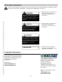
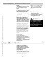
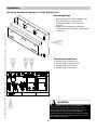
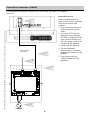
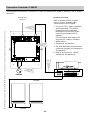
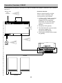
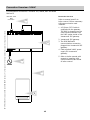
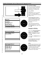
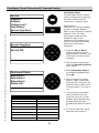
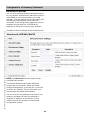
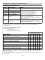
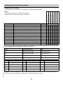
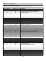
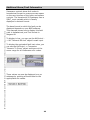
Versatronik® 505 & 505D Communication Gateway BACnet IP Document Applicable to: Communication Versatronik 505 NR2/BACIP P/N 704050 Versatronik 505D NR2/BACIP P/N 704069 Applicable Controls Vitocontrol-S, MW1 and MW2 Vitotronic 300-K, MW1B and MW2B Vitotronic 100, GC1/GC1B Vitotronic 300, GW2 Vitotronic 300, GW5B Vitotronic 200, HO1 Vitodens 200 B2HA Technical, Installation and Configuration Information Cautionary Statement The information presented in this document is only to be used by those familiar with its application and use. IMPORTANT Read and save these instructions for future reference About these instructions ! Take note of all symbols and notations intended to draw attention to potential hazards or important product information. These include “WARNING”, “CAUTION” and “IMPORTANT”. See below. ! WARNING KWE P/N 394038 Versatronik 505 and 505D BACIP Gateway V1.2 February 2014 Technical information subject to change without notice Indicates an imminently hazardous situation which, if not avoided, could result in death, serious injury or substantial product/property damage. ! CAUTION Indicates an imminently hazardous situation which, if not avoided, may result in minor injury or product/property damage. Warnings draw your attention to the presence of potential hazards or important product information. Cautions draw your attention to the presence of potential hazards or important product information CAUTION Static sensitive components may be damaged by improper handling or work within the control. Ensure all possible measures are taken to eliminate build-up of static electricity. IMPORTANT Helpful hints for installation, operation or maintenance which pertains to the product. Trademark Information Viessmann® and Vitotronic® are trademarks of Viessmann Werke GmbH & Co KG registered in the United States and other countries. BACnet® is a registered trademark of the American Society of Heating, Refrigerating and AirConditioning Engineers, Inc., 1791 Tullie Circle NE, Atlanta, GA 30329. Please visit: www.viessmann.ca www.viessmann.us For more information please visit: www.bacnet.org www.ashrea.org 2 Important Regulatory and Installation Requirements Codes The installation of this unit must be in accordance with local codes. KWE P/N 394038 Versatronik 505 and 505D BACIP Gateway V1.2 February 2014 Technical information subject to change without notice All electrical wiring is to be done in accordance with the latest edition of CSA C22,1 Part 1 and/ or local codes. In the U.S. use the National Electrical Code ANSI/NFPA 70. The installing contractor must comply with the Standard of Controls and Safety Devices for Automatically-fired Boilers, ANSI/ ASME CSD-1 where required by the authority having jurisdiction. Working on the equipment The installation, adjustment, service and maintenance of this unit must be done by a licensed professional heating contractor or persons who are qualified and experienced in the installation, service, and maintenance of similar products. There are no user serviceable parts on this control. Power supply Install power supply in accordance with the regulation of the authorities having jurisdiction or in absence of such requirements, in accordance with National Codes. Purpose of Device and Operation The Versatronik 505 gateway provides a communication translation between applicable controls and DDC systems which are capable of BACnet IP communications. The Versatronik gateway may be either part of a control panel or stand-alone control device. 3 Please carefully read this manual prior to attempting installation. Any warranty is null and void if these instructions are not followed. The completeness and functionality of field-supplied electrical controls and components must be verified by those installing the device ! WARNING More than one live circuit. See wiring diagram in this manual. Turn off power supply to control and damper/blower before servicing. Contact with live electrical components can result in serious injury or death KWE P/N 394038 Versatronik 505 and 505D BACIP Gateway V1.2 February 2014 Technical information subject to change without notice Versatronik 505 This page is intentionally left blank 4 Installation Mounting Versatronik Gateway—120VAC Unit KWE P/N 394038 Versatronik 505 and 505D BACIP Gateway V1.2 February 2014 Technical information subject to change without notice 2 1 4 1 3 Mounting Steps 1. Mount Versatronik 505 Gateway in a convenient location near the connected boiler controls control. Remove cover by loosening the two screws on either side of base to release the cover. 2. Fasten base to wall using field-supplied screws/fasteners. 3. Remove knockout and installed wire strain relief or box connector. Removal of remaining knockouts is required to make further connections. 4. Once all of the 120VAC and low voltage connections are complete and verified, reinstall the cover from Step 1. ! WARNING When extending wire there is the possibility of exposure to electromagnetic interference. Avoid running wires beside or near high voltage 120/240 VAC conductors. If proximity to high voltage conductors cannot be avoided, use stranded, twisted pair of shield design wire. Ensure that only one end of the shielding is grounded. 5 Installation Mounting Versatronik Gateway—24VAC DIN Rail Unit Mounting Steps 1 2 1. 2. 3. 4. " ! ! " # BACnet IP RJ45 connection Control LON Connection RJ45 Paralleled BUS Connection 24VAC Power Connection Connection Overview 3 1 KWE P/N 394038 Versatronik 505 and 505D BACIP Gateway V1.2 February 2014 Technical information subject to change without notice 1. Mount Versatronik 505D Gateway onto DIN rail within an enclosure in a convenient location near the boiler controls. 2. Make all the necessary connections including the field-supplied 24VAC power connection. ! ! 4 WARNING When extending wire there is the possibility of exposure to electromagnetic interference. Avoid running wires beside or near high voltage 120/240 VAC conductors. If proximity to high voltage conductors cannot be avoided, use stranded, twisted pair of shield design wire. Ensure that only one end of the shielding is grounded. 6 Versatronik 505 Dial Setting Overview Rotary Dial Setting Setting Overview 1. The rotary dial setting on the Versatronik Gateways provides addressing information for systems that may utilize a number of Versatronik Gateways. + #$ % + It is not required to make adjustments to the rotary dial setting. It should be left in the factory default position setting of 0. & & % ) ( ( ( * ( !" ' & 1 " ! ! " # KWE P/N 394038 Versatronik 505 and 505D BACIP Gateway V1.2 February 2014 Technical information subject to change without notice 1 ! 7 Connection Overview—120VAC Communication connections—Vitotronic 100, GC1/GC1B, 300 GW2 or 300 GW5B BACnet IP Connection Overview Refer to manual specific to boiler control. Ensure necessary LON communication card installed. 1 Control showing location of LON card and its location within. 2 A 3’/91cm CAT-5 cable is supplied with the gateway. The RJ45 is plugged into the control and terminates into the RJ45 socket inside of the Versatronik 505 gateway. 3 Versatronik 505 gateway. BACnetIP RJ45 Connection 4 The RJ45 BACnetIP communication connection plugged into Versatronik 505 gateway. 2 5 Plug-in power cord for 120VAC Versatronik 505 gateways. 4 3 + #$ % + & & % ( ( ) ( * ( !" & ' KWE P/N 394038 Versatronik 505 and 505D BACIP Gateway V1.2 February 2014 Technical information subject to change without notice 1 5 120VAC 8 Connection Overview—24VAC Communication connections—Vitotronic 100, GC1/GC1B, 300 GW2 or 300 GW5B BACnet IP Connection Overview Refer to manual specific to boiler/system control. Ensure necessary LON communication card installed. 1 Control showing location of LON card and its location within. 2 A 3’/91cm CAT-5 cable is supplied with the gateway. The RJ45 is plugged into the control and terminates into the RJ45 socket inside of the Versatronik 505 gateway. 4 3 Versatronik 505 gateway. 4 The RJ45 BACnetIP communication connection plugged into Versatronik 505 gateway. 2 BACnetIP RJ45 BMS Connection " ! ! 3 " # 5 Field-supplied 24VAC power supply for gateway. KWE P/N 394038 Versatronik 505 and 505D BACIP Gateway V1.2 February 2014 Technical information subject to change without notice 1 ! 5 24VAC 9 Connection Overview—120VAC Communication connections—Vitocontrol-S, CT3/VD2A or Vitotronic 300-K MW1B BACnet IP Connection Overview BACnetIP RJ45 Connection Refer to manual specific to boiler/ system control. Ensure necessary LON communication card installed. 1 A 3’/91cm CAT-5 cable is supplied with the gateway. The RJ45 is plugged into the control and terminates into the RJ45 socket inside of the Versatronik 505 gateway. Vitocontrol-S will need LON card installed. + #$ % + & & 2 % ) ( ( & 3 The RJ45 BACnetIP communication connection plugged into Versatronik 505 gateway. 4 Plug-in power cord for 120VAC Versatronik 505 gateways. ' 2 Versatronik 505 gateway. ( * ( !" KWE P/N 394038 Versatronik 505 and 505D BACIP Gateway V1.2 February 2014 Technical information subject to change without notice 3 1 4 10 Connection Overview—24VAC Communication connections—Vitocontrol-S, CT3/VD2A or Vitotronic 300-K MW1B BACnet IP " ! ! 2 Versatronik 505 gateway. " # ! 3 The RJ45 BACnetIP communication connection plugged into Versatronik 505 gateway. 4 Field-supplied 24VAC power supply for gateway. 1 A 3’/91cm CAT-5 cable is supplied with the gateway. The RJ45 is plugged into the control and terminates into the RJ45 socket inside of the Versatronik 505 gateway. 2 Refer to manual specific to boiler control. Ensure necessary LON communication card installed. KWE P/N 394038 Versatronik 505 and 505D BACIP Gateway V1.2 February 2014 Technical information subject to change without notice Connection Overview 3 BACnetIP RJ45 BMS Connection 1 4 24VAC 11 Connection Overview—120VAC Communication connections—Vitocontrol-S, MW2 for Vitodens 200, WB2B or Vitotronic 300-K, MW2B BACnet IP Connection Overview BACnetIP RJ45 Connection Refer to manual specific to boiler control. Ensure necessary LON communication card installed. 1 A 3’/91cm CAT-5 cable is supplied with the gateway. The RJ45 is plugged into the control and terminates into the RJ45 socket inside of the Versatronik 505 gateway. Communication card required for Vitocontrol-S, MW2 for Vitodens WB2B boilers. + #$ % + & & ( ( ( 3 The RJ45 BACnetIP communication connection plugged into Versatronik 505 gateway. ) 2 Versatronik 505 gateway. 2 % * ( !" 4 Plug-in power cord for 120VAC Versatronik 505 gateways. & ' KWE P/N 394038 Versatronik 505 and 505D BACIP Gateway V1.2 February 2014 Technical information subject to change without notice 4 1 5 120VAC 145KMK 145KMK 12 Connection Overview—120VAC Communication connections—Vitocontrol-S, MW2 for Vitodens 200, WB2B or Vitotronic 300-K, MW2B BACnet IP Refer to manual specific to boiler control. Ensure necessary LON communication card installed. " ! 1 A 3’/91cm CAT-5 cable is supplied with the gateway. The RJ45 is plugged into the control and terminates into the RJ45 socket inside of the Versatronik 505 gateway. ! " Connection Overview 3 2 Versatronik 505 gateway. # 4 Field-supplied 24VAC power supply for gateway. ! 3 The RJ45 BACnetIP communication connection plugged into Versatronik 505 gateway. 2 KWE P/N 394038 Versatronik 505 and 505D BACIP Gateway V1.2 February 2014 Technical information subject to change without notice BACnetIP RJ45 BMS Connection 1 4 24VAC 145KMK 145KMK 13 Connection Overview—120VAC Communication connections—Vitodens 200, WB2B, HO1 and B2HA BACnet IP Connection Overview BACnetIP RJ45 Connection Refer to manual specific to boiler control. Ensure necessary LON communication card installed. 3 + #$ 2 Versatronik 505 gateway. % + & & % 2 ) ( ( ( * ( !" 5 Refer to boiler manual with respect to installing LON communications card inside of boiler control. & ' 3 The RJ45 BACnetIP communication connection plugged into Versatronik 505 gateway. 4 Plug-in power cord for 120VAC Versatronik 505 gateways. KWE P/N 394038 Versatronik 505 and 505D BACIP Gateway V1.2 February 2014 Technical information subject to change without notice 1 1 A 3’/91cm CAT-5 cable is supplied with the gateway. The RJ45 is plugged into the control and terminates into the RJ45 socket inside of the Versatronik 505 gateway. 4 120VAC 6 14 Connection Overview—24VAC Communication connections—Vitodens 200, WB2B, HO1 and B2HA BACnet IP Connection Overview " ! ! " 2 Versatronik 505 gateway. 2 # 1 A 3’/91cm CAT-5 cable is supplied with the gateway. The RJ45 is plugged into the control and terminates into the RJ45 socket inside of the Versatronik 505 gateway. Refer to manual specific to boiler control. Ensure necessary LON communication card installed. 3 KWE P/N 394038 Versatronik 505 and 505D BACIP Gateway V1.2 February 2014 Technical information subject to change without notice BACnetIP RJ45 BMS Connection ! 3 The RJ45 BACnetIP communication connection plugged into Versatronik 505 gateway. 4 Field-supplied 24VAC power supply for Versatronik gateway. 5 Refer to boiler manual with respect to installing LON communications card inside of boiler control. 4 24VAC 1 5 15 Update Participant List for Vitocontrol-S, Cascade Control Participant Update KWE P/N 394038 Versatronik 505 and 505D BACIP Gateway V1.2 February 2014 Technical information subject to change without notice This is to be carried out after all the communication connections have been completed and the Vitocontrol-S, is coded as the error manager. Requirements: Vitocontrol-S, must be coded as the error manager (default). Refer to the Vitocontrol-S manual address 79:01. The LON participant number must be assigned in each of the Versatronik 505 gateway units. Refer to the rotary dial setting and ensure there are no duplicates. Service Diagnosis Actuator Coding Level 1 Fault History Service Functions Terminate Service? Press the OK and lined Menu button simultaneously to bring up the Service menu option and press OK. Arrow down to Service Functions and press OK. When in the Service Functions screen, ensure Subscriber Check is highlighted. Arrow up or down to highlight if not and press OK. Service Functions Participant Check Service PIN Arrow down to Delete List? and press OK. The LON Participant information will be updated as to the boiler controls and any other Versatronik LON devices. Note: Re-entering the Subscriber Check too early will result in the screen showing No Subscriber. Continue to wait for some time and then enter the Subscriber Check again. It may take time for all of the devices to report back. Participant Check Subscriber 1 Subscriber 3 Subscriber 4 Delete List? 16 Participant Check Vitocontrol-S, Cascade Control Participant Check KWE P/N 394038 Versatronik 505 and 505D BACIP Gateway V1.2 February 2014 Technical information subject to change without notice Service Diagnosis Actuator Coding Level 1 Fault History Service Functions Terminate Service? OK The participant check is used to confirm communication between the boiler controls and the Vitocontrol-S, system control. Requirements: Vitocontrol-S, must be coded as the error manager (default). Refer to the Vitocontrol-S manual address 79:01. The LON participant number must be assigned in each of the Versatronik 505 gateway units. Refer to the rotary dial setting and ensure there are no duplicates. Service Functions Participant Check Service PIN 1. Press the OK and Menu buttons simultaneously for approximately 2 seconds. This will allow the Service screen to appear. 2. With the arrow down button, select the Service Functions menu option. 3. Select Subscriber Check if not already highlighted and press OK. Participant Check Subscriber 1 Subscriber 3 Subscriber 4 Delete List? 4. With the arrow up or down buttons, select a subscriber and press OK. The screen will show the check is active and will report back if it is okay or not. Rotary Switch Position Participant Value 0 55 1 56 2 57 3 58 4 59 5 60 6 61 7 62 5. If the check was successful, select a different user by using the arrow up or down buttons. Once selected press OK and repeat the same procedure as outlined in point 4. 6. To exit the subscriber check, press the return button . 17 Configuration of Gateway KWE P/N 394038 Versatronik 505 and 505D BACIP Gateway V1.2 February 2014 Technical information subject to change without notice Configuring BACnet/IP Settings Connect your computer DIRECTLY to the BACnet interface of the gateway device. With no other devices attached (an isolated network). Either set your computer’s network connection to automatic IP Address (DHCP), or set your computer’s IP address to 192.168.88.90 (subnet mask 255.255.255.0). Restart the Gateway by cycling the power off and then on again. Open a browser window and insert the following URL: http://192.168.88.89/admin The default user name/password is "admin" and "admin" (without the quotes). This can be renamed in the Change Password screen. At this point you will see the Configuration pages. Versatronik 505 NR2/BACIP IMPORTANT: Make sure that you remember any changes made here. Configuration of Gateway Continued KWE P/N 394038 Versatronik 505 and 505D BACIP Gateway V1.2 February 2014 Technical information subject to change without notice BACnet Device Settings You can now reconfigure these settings according to your network requirements. Make sure that you press SAVE on every screen where you made changes. The new setting will not take effect until the Activate Configuration screen has been confirmed. These configuration pages can now be accessed through both the 192.168.88.89 Address, as well as the one you have selected. The BACnet Device Settings screen looks like this: Versatronik 505 NR2/BACIP NOTE: The Device ID must be unique on the entire BACnet network. The Restore Defaults and Change Password screens are very simplistic. When you select Activate Configuration, it will ask you if you want to SAVE your settings. This will then store your new settings and reboot automatically. You can now join the gateway to the rest of your network, provided you have not specified a duplicate IP Address. Any Computer on the network should now be able to access these configuration screens. 19 Configuration of Gateway Continued BACnet IP KWE P/N 394038 Versatronik 505 and 505D BACIP Gateway V1.2 February 2014 Technical information subject to change without notice Analog Output Overview Description Point Point Description Details AO1 Unit settings 0 = °C, 1 = °F AO2 Boiler 1 LON Address* AO3 Boiler 2 LON Address* AO4 Boiler 3 LON Address* AO5 Boiler 4 LON Address* Participant # / Node ID (Address 77) Default 1 -4 for Vitotronic 100 controls Rotary Dial Position for KK10LON and KW10B Add 100 (101 - 104) for KK10LON control Add 200 (201 - 204) for KW10B control AO6 Zone/Cascade/Boiler LON Address AO7 Number of Zones on the Zone/ Number of zones on the cascade/zone control. Including Cascade/Boiler the common supply zone (A1). Set 0 if no cascade or 1 through 3 for number of zones. Participant # of cascade/zone control Default 5 for Vitotronic 300 control Add 200 (205) for MW2 control (for use with WB2B boiler over KMK-BUS) *If Vitodens communicate via KMK communications with 300-K MW2B cascade control, the value that will need to be entered is 0. Only LON communications with boiler require a LON address. See example below Configuration of Analog Outputs AO2-AO7 Note: Status Light Operation Flashing=communication ON Solid or Off=no communication Analog Output Configuration Settings System Examples AO2 AO3 AO4 AO5 AO6 AO7 Single Vitotronic 100, GC1/GC1B Boiler Control 1 0 0 0 1 0 Vitotronic 200, HO1 (Vitodens 200, WB2B) 1 0 0 0 201 2 Vitodens 200 B2HA 1 0 0 0 201 1 Vitotronic 300, GW2 with 2 Mixing Valves 1 0 0 0 1 3 Vitotronic 300, GW5B with 2 Mixing Valves 1 0 0 0 1 3 Vitotronic 300-K, with 2 Vitotronic 100, GC1 (high temp & 1 MV) 1 2 0 0 5 2 Vitotronic 300-K, with 4 Vitotronic 100, GC1 (high temp & 2 MV) 1 2 3 4 5 3 Vitotronic 300-K (Vitodens 200, WB2B/B2HA) Boiler KMK Comm. 0 0 0 0 205 3 Vitotronic 050/200-H, HK1 Mixing Valve Control 0 0 0 0 10 1 Vitotronic 050/200-H, HK3 Mixing Valve Control 0 0 0 0 10 3 Note: Analog output AO7 is a function of AO6. The AO7 setting determines the number of heating circuits of the AO6 control. The AO2 through to AO6 settings are based on the programmed participant number at address 77 of the boiler controls. 20 Analog Input Overview Point AI1 Point Description Unit Boiler 1 actual temperature °C/°F Vitotronic 300-K, MW2** Vitotronic 300, GW2 Vitotronic 200, HO1 **Vitodens boilers which communicate via KMK to the 300-K MW2B may not provide some points of information that LON communication does. Boiler/burner faults do not appear directly from the boiler. It is necessary to pick up the burner/boiler fault from the Cascade Fault Status. Vitodens 200, B2HA Vitotronic 100, GC1 KWE P/N 394038 Versatronik 505 and 505D BACIP Gateway V1.2 February 2014 Technical information subject to change without notice Note: Temperature values only possible with specific installed sensors based on particular installation Vitotronic 333/300-K MW1 Analog Inputs Values which can be read from the Versatronik 505 NR2/BACIP Gateway Points Available Y/N Y Y Y Y Y Y N AI2 Boiler 1 actual return temperature sensor 1 (17A for GC1/GC1B) °C/°F Y N N Y Y AI3 Boiler 1 modulation °C/°F Y N N Y Y Y AI4 Boiler 1 flue gas actual temperature °C/°F Y Y Y Y Y N AI5 Boiler 1 fault code (Appendix A) N/A Y Y Y Y Y N AI6 Boiler 1 relay state (Appendix B) N/A Y Y Y Y Y N AI7 Boiler 2 actual temperature °C/°F N N N N Y Y AI8 Boiler 2 actual return temperature sensor 1 (17A for GC1/GC1B) °C/°F N N N N Y N Boiler 2 modulation °C/°F N N N N Y Y AI10 AI9 Boiler 2 flue gas actual temperature °C/°F N N N N Y N AI11 Boiler 2 fault code (Appendix A) N/A N N N N Y N N AI12 Boiler 2 relay state (Appendix B) N/A N N N N Y AI13 Boiler 3 actual temperature °C/°F N N N N Y Y AI14 Boiler 3 actual return temperature sensor 1 (17A for GC1/GC1B) °C/°F N N N N Y N AI15 Boiler 3 modulation °C/°F N N N N Y Y AI16 Boiler 3 flue gas actual temperature °C/°F N N N N Y N AI17 Boiler 3 fault code (Appendix A) N/A N N N N Y N N AI18 Boiler 3 relay state (Appendix B) N/A N N N N Y AI19 Boiler 4 actual temperature °C/°F N N N N Y Y AI20 Boiler 4 actual return temperature sensor 1 (17A for GC1/GC1B) °C/°F N N N N Y N AI21 Boiler 4 modulation °C/°F N N N N Y Y AI22 Boiler 4 flue gas actual temperature °C/°F N N N N Y N AI23 Boiler 4 fault code (Appendix A) N/A N N N N Y N AI24 Boiler 4 relay state (Appendix B) N/A N N N N Y N AI25 Zone/Cascade/Boiler Outdoor temperature °C/°F N Y Y Y Y Y AI26 Zone/Cascade/Boiler Relay State (Appendix B) N/A N Y Y Y Y Y AI27 Zone/Cascade/Boiler Fault Code (Appendix A) N/A N Y Y Y Y Y AI28 Zone/Cascade/Boiler DHW Set-Point °C/°F Y Y Y Y Y Y AI29 Zone/Cascade/Boiler DHW Actual Temperature °C/°F Y Y Y Y Y Y AI30 Zone/Cascade/Boiler Zone A1 Supply Set-Point °C/°F Y Y Y Y Y Y AI31 Zone/Cascade/Boiler Zone A1 Supply Actual Temperature °C/°F N Y Y Y Y Y AI32 Zone/Cascade/Boiler Zone A1 Actual Return Temperature °C/°F N N N Y Y Y AI33 Zone/Cascade/Boiler Zone A1 Curve Shift °K N Y Y Y Y Y AI34 Zone/Cascade/Boiler Zone A1 Curve Slope N/A N Y Y Y Y Y 21 Analog Input Overview Continued Point Point Description Unit Vitotronic 300-K, MW2 Vitotronic 333/300-K MW1 Vitotronic 300, GW2 Vitotronic 200, HO1 Vitotronic 100, GC1 KWE P/N 394038 Versatronik 505 and 505D BACIP Gateway V1.2 February 2014 Technical information subject to change without notice Note: Temperature values only possible with specific installed sensors based on particular installation. Vitodens 200, B2HA Analog Inputs Continued Values which can be read from the Versatronik 505 NR2/BACIP Gateway Points Available Y/N AI35 Zone/Cascade/Boiler Zone A1 Curve Room Temp. Normal °C/°F N Y Y Y Y Y AI36 Zone/Cascade/Boiler Zone A1 Curve Room Temp. Reduce °C/°F N Y Y Y Y Y AI37 Zone/Cascade/Boiler Zone M2 Supply Set-Point °C/°F N Y Y Y Y Y AI38 Zone/Cascade/Boiler Zone M2 Supply Actual Temperature °C/°F N Y Y Y Y Y AI39 Zone/Cascade/Boiler Zone M2 Curve Shift °K N Y Y Y Y Y AI40 Zone/Cascade/Boiler Zone M2 Curve Slope N/A N Y Y Y Y Y AI41 Zone/Cascade/Boiler Zone M2 Curve Room Temp. Normal °C/°F N Y Y Y Y Y AI42 Zone/Cascade/Boiler Zone M2 Curve Room Temp. Reduce °C/°F N Y Y Y Y Y AI43 Zone/Cascade/Boiler Zone M3 Supply Set-Point °C/°F N N N Y Y Y AI44 Zone/Cascade/Boiler Zone M3 Supply Actual Temperature °C/°F N N N Y Y Y AI45 Zone/Cascade/Boiler Zone M3 Curve Shift °K N N N Y Y Y AI46 Zone/Cascade/Boiler Zone M3 Curve Slope N/A N N N Y Y Y AI47 Zone/Cascade/Boiler Zone M3 Curve Room Temp. Normal °C/°F N N N Y Y Y AI48 Zone/Cascade/Boiler Zone M3 Curve Room Temp. Reduce °C/°F N N N Y Y Y Multi-state Burner Information—All Boiler Controls Point Point Description Unit MI1 Boiler 1 Burner State *See table below MI2 Boiler 2 Burner State *See table below MI3 Boiler 3 Burner State *See table below MI4 Boiler 4 Burner Stage *See table below State Value State Value State Value 1 Off 5 30% 9 70% 2 Fault 6 40% 10 80% 3 10% 7 50% 11 90% 4 20% 8 60% 12 100% Note: The burner percentage is only a control approximation and does not reflect the actual position. Consult with burner manual or manufacturer for signal output from burner 22 Analog Outputs Overview Point Vitotronic 300-K, MW2 Vitotronic 333/300-K MW1 Vitotronic 300, GW2 Vitotronic 200, HO1 Vitotronic 100, GC1 KWE P/N 394038 Versatronik 505 and 505D BACIP Gateway V1.2 February 2014 Technical information subject to change without notice Note: Temperature values only possible with specific installed sensors based on particular installation. Vitodens 200, B2HA Analog Outputs Values which can be “written” to the Versatronik 505 NR2/BACIP Gateway Point Description Unit AO1 Unit settings – 0 = °C, 1 = °F N/A Points Available Y/N Y Y Y Y Y Y AO2 Boiler 1 LON Address (Configured Value must be set during commissioning) N/A Y Y Y Y N N N AO3 Boiler 2 LON Address (Configured Value must be set during commissioning) N/A Y Y Y Y N AO4 Boiler 3 LON Address (Configured Value must be set during commissioning) N/A Y Y Y Y N N AO5 Boiler 4 LON Address (Configured Value must be set during commissioning) N/A Y Y Y Y N N AO6 Zone/Cascade/Boiler LON Address (Configured Value must be set during commissioning) Number of Zones on the Zone/Cascade/Boiler (Configured Value must be set during commissioning) N/A N Y Y Y Y Y N/A N Y Y Y Y Y Zone/Cascade/Boiler DHW Writeable Set-Point °C/°F Y Y Y Y Y Y Y AO7 AO8 AO9 Zone/Cascade/Boiler Zone A1 Writeable Curve Shift °K N Y Y Y Y AO10 Zone/Cascade/Boiler Zone A1 Writeable Curve Slope N/A N Y Y Y Y Y AO11 Zone/Cascade/Boiler Zone A1 Writeable Curve Room Temp. Normal °C/°F N Y Y Y Y Y AO12 Zone/Cascade/Boiler Zone A1 Writeable Curve Room Temp. Reduce °C/°F N Y Y Y Y Y AO13 Zone/Cascade/Boiler Zone A1 Writeable Supply Set-Point °C/°F N Y Y Y Y Y AO14 Zone/Cascade/Boiler Zone M2 Writeable Curve Shift °K N Y Y Y Y Y AO15 Zone/Cascade/Boiler Zone M2 Writeable Curve Slope N/A N Y Y Y Y Y AO16 Zone/Cascade/Boiler Zone M2 Writeable Curve Room Temp. Normal °C/°F N Y Y Y Y Y AO17 Zone/Cascade/Boiler Zone M2 Writeable Curve Room Temp. Reduce °C/°F N Y Y Y Y Y AO18 Zone/Cascade/Boiler Zone M2 Writeable Supply Set-Point °C/°F N Y Y Y Y Y AO19 Zone/Cascade/Boiler Zone M3 Writeable Curve Shift °K N N N Y Y Y AO20 Zone/Cascade/Boiler Zone M3 Writeable Curve Slope N/A N N N Y Y Y AO21 Zone/Cascade/Boiler Zone M3 Writeable Curve Room Temp. Normal °C/°F N N N Y Y Y AO22 Zone/Cascade/Boiler Zone M3 Writeable Curve Room Temp. Reduce °C/°F N N N Y Y Y AO23 Zone/Cascade/Boiler Zone M3 Writeable Supply Set-Point °C/°F N N N Y Y Y 23 Fault Codes Appendix A—Fault Codes Error codes for Viessmann control units based on controls/equipment installed KWE P/N 394038 Versatronik 505 and 505D BACIP Gateway V1.2 February 2014 Technical information subject to change without notice Fault Code (hex) Fault Code (Dec) Description 00 00 System without fault 0F 15 Perform maintenance check-up 10 16 Short circuit, outdoor temperature sensor 18 24 Interruption, outdoor temperature sensor 20 32 Short circuit, supply temperature sensor HC1/system 28 40 Interruption, supply temperature sensor HC1/system 30 48 Short circuit, boiler water temperature sensor 38 56 Interruption, boiler water temperature sensor 40 64 Short circuit, supply temperature sensor heating circuit 2 41 65 Short circuit, return temperature sensor heating circuit 2 44 68 Short circuit, supply temperature sensor heating circuit 3 45 69 Short circuit, return temperature sensor heating circuit 3 48 72 Interruption, supply temperature sensor heating circuit 2 49 73 Interruption, return temperature sensor heating circuit 2 4C 76 Interruption, supply temperature sensor heating circuit 3 4d 77 Interruption, return temperature sensor heating circuit 3 50 80 Short circuit, DHW tank temperature sensor 51 81 Short circuit, DHW tank temperature sensor 2 58 88 Interruption, DHW tank temperature sensor 59 89 Interruption, DHW tank temperature sensor 2 60 96 Short circuit, return temperature sensor 17 68 104 Interruption, return temperature sensor 17 70 112 Short circuit, supply/return temperature sensor 17B 78 120 Interruption, supply/return temperature sensor 17B 92 146 Solar: collector temperature short circuit 93 147 Solar: collector return temperature short circuit 94 148 Solar: collector DHW tank temperature sensor short circuit 9A 154 Solar: collector temperature sensor open circuit 9B 155 Solar collector return temperature sensor open circuit 9C 156 Solar: DHW tank temperature sensor open circuit 9F 159 Solar: general fault message A7 167 Fault control unit wireless clock module AE 174 Internal fault mixing valve AF 175 Internal fault mixing valve b0 176 Short circuit, flue gas temperature sensor b1 177 Communication fault, programming unit (internal) b4 180 Internal fault b5 181 Internal fault b6 182 Internal fault, invalid hardware recognition b7 183 Internal fault, boiler protection coding card b8 184 Interruption, flue gas temperature sensor bA 186 Fault, mixing valve module (KM-BUS) bC 188 Fault, Vitotrol heating circuit 1 (KM-BUS) bd 186 Fault, Vitotrol heating circuit 2 (KM-BUS) bE 190 Fault, Vitotrol heating circuit 3 (KM-BUS) C1 193 External fault indication, boiler C2 194 Communication fault solar control unit (KM-BUS) 24 Fault Codes Continued KWE P/N 394038 Versatronik 505 and 505D BACIP Gateway V1.2 February 2014 Technical information subject to change without notice Appendix A—Fault Codes Continued Error codes for Viessmann control units based on controls/equipment installed Fault Code (hex) Fault Code (Dec) Description C5 197 Fault, speed controlled pump heating circuit 1 (KM-BUS) C6 198 Fault, speed controlled pump heating circuit 2 (KM-BUS) C7 199 Fault, speed controlled pump heating circuit 3 (KM-BUS) C8 200 Fault, water level control C9 201 Fault, maximum pressure CA 202 Fault, minimum pressure/maximum pressure 2 Cb 203 Fault, maximum pressure 2 CC 204 Reserved, external periphery Cd 205 Communication fault, Vitocom 300 (KM-BUS) CE 206 Communication fault, fault indicator module (KM-BUS) CF 207 Communication fault: wrong LON module d1 209 Burner fault, boiler d4 212 Fixed high limit fault, boiler d5 213 Cascade: boiler is not responding d6 214 External fault 1, plug-in adaptor d7 215 External fault 2, plug-in adaptor d8 216 External fault 3, plug-in adaptor dA 218 Short circuit, room temperature sensor heating circuit 1 db 219 Short circuit, room temperature sensor heating circuit 2 dC 220 Short circuit, room temperature sensor heating circuit 3 dd 221 Interruption, room temperature sensor heating circuit 1 dE 222 Interruption, room temperature sensor heating circuit 2 dF 223 Interruption, room temperature sensor heating circuit 3 E0 224 Fault, external participant/device connected to LON E4 228 Fault power supply voltage E5 229 Internal fault combustion control unit E6 230 Flue gas/air supply system blocked F0 240 Communication fault combustion control unit F1 241 Flue gas temperature limit has tripped F2 242 Temperature limit has tripped F3 243 Flame signal is present at burner start F4 244 Flame signal is not present F5 245 Air pressure switch not open for burner start F6 246 Gas pressure switch not open for burner start F7 247 Air pressure sensor short circuit or offset value outside of tolerances F8 248 Fuel valve closure delayed F9 249 Blower speed too low at burner start FA 250 Blower speed too high at burner start FC 252 Control of modulation valve defective FD 253 Fault combustion control unit FE 254 Coding plug defective or wrong EMV error FF 255 Internal fault 25 Additional Alarm/Fault Information KWE P/N 394038 Versatronik 505 and 505D BACIP Gateway V1.2 February 2014 Technical information subject to change without notice Viessmann controls show fault codes in hexadecimal format to conserve screen space on the user interface of the boiler and system controls. The Versatronik 505 gateway uses a SNVT_count variable which is usually displayed in decimal format. The base-format in which this fault can be displayed depends on your BMS software. This example shows how to display this fault code in hexadecimal, and Text format in Niagara AX. To display in hex, you can use the KitControl > Util “Numeric Bit And” object’s mask input. To display the equivalent fault text value, you can use the KitControl -> Conversion “Numeric To Enum” object and type out the enum range for all Viessmann error codes. These values can now be displayed on a px webpage by pointing a Bound Label to the appropriate slot values. 26 Status Information 2 Vitotronic 050/200H HK1M Vitotronic 050 HK1 Panel Vitotronic 050 HK3 Panel Vitotronic 300-K, MW1B, MW2B Vitotronic 200, HO1/Vitodens B2HA bit 21 : Re-circulation pump Vitotronic 333/300-K MW1 1 Vitotronic 300, GW2/GW5B Bit Relay State 0 bit 20 : DHW tank loading pump Vitotronic 100, GC1/GC1B KWE P/N 394038 Versatronik 505 and 505D BACIP Gateway V1.2 February 2014 Technical information subject to change without notice Appendix B—Status Information x = always available for this device k = dependent on configuration of device n = not available for this device k k k n k k k k n k k n k k k k 2 bit 2 : Heating circuit pump 1 n k k x x k k x 3 bit 23 : Heating circuit pump 2 n k k n n k k k 4 4 bit 2 : Heating circuit pump 3 n k k n n k k n 5 bit 25 : Night-time contact HKP 1 n k k x x k k x 6 6 bit 2 : Night-time contact HKP 2 n k k n n k k k 7 bit 27 : Night-time contact HKP 3 n k k n n k k n 8 8 bit 2 : Supply pump n n n k k k n n 9 bit 29 : Primary pump heat exchanger set for DHW tank loading k k k n k k k n n n n n n n n k k k k n n n n k n n n n n n k x k k k n n n n n n n n n n n n k x n n n n n n n 13 bit 2 : ThermControl switching contact k n n n n n n n bit 213: Diverting valve in DHW position n n n n n n n k 14 bit 2 : Burner 1 stage x x n n n n n n 15 bit 215: Burner fault x x n n n n n n n n n n n n n x 9 bit 2 : DHW tank pump 10 bit 210: Boiler circuit and distribution (common supply) pump 10 bit 2 : Internal Pump 11 bit 211: Shunt pump 11 bit 2 : Diverting valve in space heating position 12 bit 212: Flue gas heat exchanger pump 13 14 st 15 bit 2 : Compiled fault 27 Technical Information—120VAC 3 7 8 + + #$ 9 % % ) ( ( ( * ( 6 & & F1'160mA & KWE P/N 394038 Versatronik 505 and 505D BACIP Gateway V1.2 February 2014 Technical information subject to change without notice 5 !" 10 4 2 1 PCB Identifiers Specifications 1 120VAC Power Supply Connections Voltage Requirements 120VAC 2 Fuse Fuse Rating 160mA Time Delay 3 Service Button Power 4VA 4 LON Connections to BMS 5 RJ45 Connection to BMS BACnet Communication Connections Supplied cable between devices 6 Addressing selector for multiple modules 7 COM3 for multiple BUS connections 8 COM4 RJ45 Connection to control 9 Power LED indicator CAUTION Static sensitive components may be damaged by improper handling or work within the control. Ensure all possible measures are taken to eliminate build-up of static electricity. 10 Service LED 28 Technical Information 4 6 7 " ! # ! " KWE P/N 394038 Versatronik 505 and 505D BACIP Gateway V1.2 February 2014 Technical information subject to change without notice 9 8 2 5 3 ! 1 PCB Identifiers Specifications 1 24VAC Power Supply Connections Voltage Requirements 24VAC 2 Power LED indicator Fuse Rating N/A 3 BACnet RJ45 BMS Connection Power 4VA 4 Addressing dial for multiple units 5 COM4 RJ45 Connection to control Communication Connections Supplied cable between devices 6 COM3 for multiple BUS connections 7 Service button 8 Service LED 9 LON Connections to BMS CAUTION Static sensitive components may be damaged by improper handling or work within the control. Ensure all possible measures are taken to eliminate build-up of static electricity. 29 KWE P/N 394038 Versatronik 505 and 505D BACIP Gateway V1.2 February 2014 Technical information subject to change without notice KWE Technologies Group 750 McMurray Road Waterloo, Ontario, Canada N2V 2G5 Tel: (519) 747-5042 Fax: (519) 747-4448 www.kwe-tech.com [email protected] 30