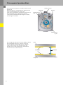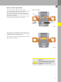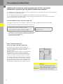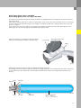
1
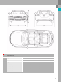
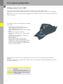
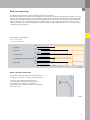
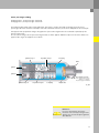
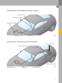
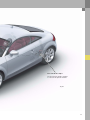
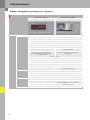
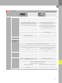
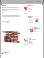
380
Vorsprung durch Technik www.audi.de
Service Training
Audi TT Coupé ‘07
Self-Study Programme 380
All rights reserved.
Technical specifications
subject to change without
notice.
Copyright
AUDI AG
I/VK-35
[email protected]
Fax +49-841/89-36367
AUDI AG
D-85045 Ingolstadt
Technical status: 05/06
Printed in Germany
A06.5S00.25.20
Self-study programmes on the TT Coupé
Introduction
SSP 380 Audi TT Coupé ‘07
The first generation of the Audi TT Coupé, named after the legendary "Tourist Trophy" race in the UK, was
a milestone in automotive design.
The design followed the pure geometry, with central motives being the circle, particularly distinctive on the
wheel arches, the arches of the roofline, the front end and the rear end.Audi has taken this genetic code and
developed it in authentic style.
In the new TT, the geometric shapes merge fluidly with one another.The concave and convex arches radiate
dynamism and movement while lending the TT Coupé the character of an athletic sculpture thrusting
forwards.
–
–
–
–
–
–
–
Body
Occupant protection
Engine
Suspension system
Electrical system
Air conditioning
Infotainment
Order number: A06.5S00.25.20
The front end of the new TT Coupé has gained in expressiveness and resoluteness, the most distinctive
element being the singelframe radiator grille.
Unlike the predecessor model, the rear end has a completely different outline to the front end. The rear lights
create a three-dimensional effect by virtue of their visual depth. The trapezoidal cut-out around the license
plate continues the flowing lines of the boot lid. The powerful exhaust tailpipes, wide diffusor and central rear
fog light are borrowed straight from motorsport.
SSP 381 Audi TT Coupé ‘07 Suspension System
The dynamic impression conveyed by the Audi TT Coupé also stems from its modified proportions.
–
–
–
–
On the exterior it is now: - 137 mm longer
- 78 mm wider
Front axle
Rear axle
Shock absorber system
Brake system
Order number: A06.5S00.26.20
SSP 382 Audi TT Coupé ‘07 Electrical and Infotainment Systems
–
–
–
–
Networking
Bus topology
Convenience electronics
Infotainment
Order number: A06.5S00.27.20
SSP 383 Audi TT Coupé ‘07 - Body
–
–
–
–
–
–
380_043
Excellence in design & performance
Audi Space Frame
Production processes and joining methods
Surface finish
Electromechanical rear spoiler
Repair concept
Passive safety concept
Order number: A06.5S00.28.20
Contents
Introduction . . . . . . . . . . . . . . . . . . . . . . . . . . . . . . . . . . . . . . 4
Body . . . . . . . . . . . . . . . . . . . . . . . . . . . . . . . . . . . . . . . . . . . . 6
Occupant protection . . . . . . . . . . . . . . . . . . . . . . . . . . . . . . 8
Engine . . . . . . . . . . . . . . . . . . . . . . . . . . . . . . . . . . . . . . . . . . 22
Running gear. . . . . . . . . . . . . . . . . . . . . . . . . . . . . . . . . . . . 28
Electrical system . . . . . . . . . . . . . . . . . . . . . . . . . . . . . . . . . 38
Air conditioning . . . . . . . . . . . . . . . . . . . . . . . . . . . . . . . . . 42
Infotainment . . . . . . . . . . . . . . . . . . . . . . . . . . . . . . . . . . . . 50
The self-study programme teaches the design and function of new vehicle models,
new automotive components or new technologies.
The self-study programme is not a repair manual!
All values given are intended as a guideline only, and refer
to the software version valid at the time of publication of the SSP.
For maintenance and repair work, always refer to the current technical literature.
Reference
Note
Introduction
Overview
Dimensions of the Audi TT Coupé ‘07.
380_054
Audi TT Coupé ‘07
2.0l HS
2.0l s-tronic
3.2l HS qu
3.2l s-tronic qu
Permissible gross weight in kg
1660
1680
1810
1830
Kerb weight without driver in kg
1260
1280
1410
1430
0.30
0.31
Drag coefficient Cw
Fuel tank capacity in litres
Body type
Height of loading sill in mm
Luggage compartment volume in l
4
0.30
55
60
Audi Space Frame (ASF)
790
290 (700l with rear-seat back folded forward)
380_040
Body / dimensions
Length in mm
4178
+ 137
Width in mm
1842
+ 78
Height in mm
1352
+6
Wheelbase in mm
2468
+ 46
Front track width in mm
1572
+ 26
Rear track width in mm
1558
+ 30
Number of seats
2+2
5
Body
Audi Space Frame ASF of the Audi TT Coupé ´07
The development targets for the bodyshell of the Audi TT Coupé ‘07
With a weight advantage of 48 % over a comparable all-steel bodyshell, not to mention the optimised weight
distribution, the new composite aluminium-steel spaceframe body of the TT Coupé marks yet another
milestone in the development of modern Audi bodyshells.
Crash safety of the bodyshell is enhanced by load-bearing structures at the front, sides and rear end with
a heavy emphasis on pedestrian safety.
To ensure efficient volume bodyshell production, various new joining and production techniques are
employed.
The repair concept is to a large extent based on the well-known aluminium repair concept, although
combining the materials aluminium and steel meant, of course, that new approaches had to be taken.
Sill section Audi TT Coupé ‘07
Four-chamber extruded section
380_062
Sill section Audi A8
Three-chamber extruded section
380_063
6
Technological concept
Sheet-steel parts are used for the first time in the ASF of the Audi TT Coupé ‘07, in addition to aluminium
castings, aluminium extruded sections and aluminium sheet-metal parts. Collectively they form the body
structure. Vehicle weight distribution is optimised by using sheet-steel parts at the rear end of the body.
This has a direct bearing on sporting characteristics such as driving dynamics and acceleration, as well as
safety characteristics such as stopping distance and driving stability Despite the partial use of sheet-steel
parts, the total body weight of 277 kg including attachments, such as doors and lids, is approx. 48 % less than
that of a comparable full steel body. Although the TT Coupé has grown considerably in size, the overall weight
of the vehicle has been reduced through the use of the aluminium steel bodyshell.
The body structure of the Audi TT Coupé ‘07 has higher strength and 50 % higher torsional rigidity than its
predecessor.
Component parts overview
22
Aluminium castings
129
Sheet-aluminium parts
19
Extruded aluminium sections
107
Sheet-steel parts (galvanised)
380_061
Reference
For details of design and function,
refer to Self-Study Programme 383
Audi TT Coupé ‘07 - Body.
7
Occupant protection
Occupant protection system in the Audi TT Coupé ‘07
The Audi TT Coupé ‘07 is a high-end sports car. However, the occupant protection system matches the
vehicle's driving dynamics in every respect. Creating a sports car with a high occupant protection potential is
always a big challenge. This challenge was met by the TT Coupé development team.
The occupant protection system of the Audi TT Coupé ‘07 is composed of the following components and
systems:
–
–
–
–
–
–
–
–
–
Airbag control unit
Dual-stage driver and front passenger airbags
Front side airbags
Central crash sensor for front airbag, so-called "upfront" sensor for head-on collision detection
Side impact detection sensors in the front doors
Front belt tensioners
Battery isolation igniter
Belt switch, driver side
Belt-on indicator
Due to the different criteria and statutory requirements set by the various markets, the equipment
specifications can vary. This applies particularly to the US market.
Legend
E24 Driver side belt switch
E224 Front passenger side airbag deactivation key
switch
G179 Side airbag crash sensor, driver side
G180 Side airbag crash sensor, front passenger
side
G283 Driver side front airbag crash sensor (central)
8
380_005
J234
J285
J393
J533
J623
Airbag control unit
Control unit with display in dash panel insert
Convenience system central control unit
Data bus diagnostic interface (Gateway)
Engine control unit
K19 Seat belt warning system warning lamp
K75 Airbag warning lamp
K145 Front passenger side airbag deactivated
warning lamp (PASSENGER AIRBAG OFF)
N95
N250
N131
N132
N153
N154
N199
N200
N253
Airbag igniter, driver side
Driver side airbag igniter -2Front passenger side airbag igniter 1
Front passenger side airbag igniter 2
Driver seat belt tensioner igniter -1Front passenger seat belt tensioner igniter -1Side airbag igniter, driver side
Side airbag igniter, front passenger side
Battery isolation igniter
T16
16-pin connector, diagnosis connection
9
Occupant protection
Airbag control unit J234
Airbag control unit J234 and integrated electronics have the task of detecting a collision.
In the Audi TT Coupé ‘07 the airbag control unit is attached to the vehicle body in the area of the handbrake
lever.
The airbag control unit is integrated in the CAN powertrain data bus so that it can exchange information with
other control units.
The airbag electronics basically have the following
main tasks:
– Collision detection (front, side, rear)
– Defined deployment of the belt tensioners,
airbags and battery disconnect
– Defined deployment of the second front airbag
stage
– Evaluation of all input information
– Permanent monitoring of the complete airbag
system
– Independent energy supply via capacitor for
a defined period of time
(approx. 150 ms)
– Fault display via failure warning lamp
– Storage of error / and crash information
– Indication of a collision event to other system
components via the powertrain CAN bus or
discrete collision output (conventionally wired)
– Activate seat belt reminder
380_008
To find out which components need replacing after an accident, refer to the valid Workshop Manual in
ElsaWin.
An airbag control unit can only be replaced with a VAS tester running the "Guided Fault Finding" or "Guided
Functions" application.
Reference
For more information about the
airbag control unit J234, refer to SelfStudy Programmes 323 Audi A6 `05
and 361 Audi Q7.
10
Belt-on warning
The Audi TT Coupé ‘07 has a belt-on warning function for the driver.
The airbag control unit evaluates the information from the driver side belt switch E24 after ignition "on". If the
driver is not wearing a seat belt, a visual warning is given by the seat belt warning system warning lamp K19
integrated in the dash panel insert.If the system determines that the vehicle is moving, an audio warning is
given in addition to the visual warning.As long as the ignition is on, the airbag control unit monitors the
switched condition of seat belt switch E24. If seat belt status changes while terminal 15 is "on", the seat belt
reminder will be reactivated.
Time diagram for seat belt reminder
Visual and audio signals
- Delayed seat belt fastening
ON
Terminal 15
OFF
V > 25 kph
Road speed
v < 25 kph
yes
Seat belt fastened
No
ON
Seat belt warning system warning lamp
OFF
ON
Audio signal
OFF
Time
361_016
Driver side belt switch E24
The "belt-on warning" function needs information
on whether the driver's seat belt is fastened or not.
Seat belt switch E24 in the belt buckle is
a mechanically actuated open-close switch.
The airbag control unit uses a resistance
measurement to establish whether the seat belt is
fastened or not.
380_065
11
Occupant protection
Airbag
The Audi TT Coupé ‘07 has two-stage front airbags on the driver and front passenger sides.
The airbag control unit selects the time interval between the two ignition stages (approx. 5 ms to 30 ms)
according to severity and type of crash.
The loads acting on the driver or front passenger during an accident can be reduced through time-staggered
ignition of the propellant charges.
Both propellant charges are always ignited. This ensures that no propellant charge remains active after the
airbag is deployed.
Driver airbag
Airbag igniter I, driver side N95
Airbag igniter II, driver side N250
A gas generator with two pyrotechnic propellant charges is integrated in the driver's airbag.
Igniter I is activated electrically by the airbag control unit J234. The igniter flame passes through the container
and ignites the ignition charge in the container. If the pressure produced by the ignition of the ignition charge
is high enough, the flame will break through the container and reach the propellant charge through the
perforated tube. Propellant charge I ignites and combusts. The developing gas destroys the foil seal, and
filtered gas flows through the air outlet into the airbag. After a defined interval has expired, the airbag control
unit activates igniter II, which in turn ignites propellant charge II directly. The gas produced by combustion of
the propellant material flows through the raised end cap into the combustion chamber of propellant charge I.
From here the gas flows through the filter into the airbag.
Perforated tube
Ignition charge container
Propellant charge II
End cap
Casing
Foil seal
Foil seal
Air outlet
Air outlet
Filter
Filter
Igniter I
Propellant charge I
Igniter II
380_003
12
Front passenger airbag
Airbag igniter 1, front passenger side N131
Airbag igniter 2, front passenger side N132
An airbag module with a two-stage hybrid gas generator is used in the Audi TT Coupé ‘07 on the front
passenger side.This module is already in use in the Audi Q7. However, it has been adapted for the TT Coupé.
Two pyrotechnic propellant charges integrated in a pressurised gas bottle are activated separately by the
airbag control unit.
The so-called cold gas in the pressurised gas bottle is under approx. 250 bar of pressure and is a mixture of
approx. 98 % argon and approx. 2 % helium.
Ignition charge I
Propellant charge I
Coil spring
Filter
Igniter I
Igniter II
Pressurised gas bottle
Gas: approx. 98 % argon
approx. 2 % helium
Pressure: approx. 250 bar
Ignition charge II
Propellant charge II
Coil spring
Rupture disc
361_002
Reference
For more information about the
function of the front passenger front
airbag, refer to Self-Study Programme
361 Audi Q7.
13
Occupant protection
Side airbags
Side airbag igniter, driver side N199
Side airbag igniter, front passenger side N200
Airbag modules which cover both the body and
head areas - so-called head-thorax airbags - are
used as side airbags.
Tubular gas generators filled with solid propellant
inflate the airbags with gas in the event of a crash.
380_004
The airbag control unit J234 energises the corresponding side airbag igniter. The ignition charge which is
ignited by the igniter in turn ignites the actual propellant charge. The developing gas is treated and cooled by
the metal filter, whereupon it unfolds and inflates the airbag.
Ignition charge
Detonator
Metal filter
Propellant charge
Air outlet
Air outlet
361_022
14
Driver seat belt tensioner igniter -1- N153
Front passenger seat belt tensioner igniter -1- N154
The Audi TT Coupé ‘07 is equipped with redesigned
belt tensioners for the driver and front passenger.
These belt tensioners are so-called "band
tensioners".
The TT Coupé for the North American market is also
equipped with these belt tensioners.
Seat belt
Inertia-reel seatbelt
If the rear seats in the TT Coupé are equipped with
Isofix fixing eyelets, belt tensioners are also
installed for these seats.
Foil
The workshop manual (ElsaWin) applicable to the
vehicle describes the tests which must be made to
detect an activated belt tensioner (band tensioner).
An activated belt tensioner can be detected, among
other things, by virtue of the fact that the foil
located on the side of the belt tensioner housing is
detached from the housing.
Belt tensioner unit
380_030
A metal band is wrapped around the seat belt
retractor shaft.
Both open ends are connected to the seat belt
retractor shaft.
The closed end is looped around the belt tensioner
igniter.
Electrical connector
Metal band
Detonator
Seat belt retractor
shaft
Metal band loop
380_027
15
Occupant protection
The belt tensioner igniter is located inside the metal
band loop.
When the igniter is activated by the airbag control
unit, the resultant pressure causes the
loop of the metal band to expand.The movement of
the metal band exerts a pull on the seat belt
retractor shaft, which thereupon begins to rotate,
tensioning the seat belt.
Electrical connector
Metal band
Detonator
Seat belt retractor
shaft
Metal band loop
380_028
The casing and casing cover surface between which
the metal band moves are coated in a layer of
silicon. When the metal band moves, it thrusts
a part of this silicon layer ahead of itself and
thereby ensures that a tight seal is maintained.
Pressure losses are thus reduced.
Casing
Silicon layer
Casing cover
16
Metal band
380_026
Battery isolation igniter N253
The battery isolation igniter has the task of
disconnecting the starter and alternator leads from
the vehicle battery in the event of a crash.
Use is made of a pyrotechnic component which is
activated by the airbag control unit J234 whenever
the airbag is deployed.
During a rear collision, only the belt tensioner and
the battery isolation igniter are activated.
Battery isolation igniter
Pin
Connecting
element with
terminals
Detonator
332_030
If the pyrotechnic propellant charge is ignited, the
resultant gas pressure displaces the pin on a piston
and disconnects the two terminals.
After deployment of the airbag, the battery isolation
igniter must be replaced.
361_024
Reference
Further information on the function
of the battery isolation igniter, refer
to Self-Study Programme 361
Audi Q7.
17
Occupant protection
Additional functions and components of the occupant
protection system for the North American market
The additional functions and components of the occupant protection system for the North American market
are described on the following pages.
The occupant protection system is equipped with additional functions and components,
e.g. second crash sensor for front airbag, so that the Audi TT Coupé ‘07 meets the statutory and marketspecific requirements for the US market.
Seat occupied detection, front passenger side
The front passenger side seat occupied recognition system was largely adopted from the Audi Q7.
The system basically comprises the following components:
–
–
–
–
Seat squab
Sensor mat for seat occupied recognition
Pressure sensor for seat occupied recognition G452
Seat occupied recognition control unit J706
These components form a single
unit and must not be separated
from each other.
– Front passenger side belt switch E25
– Seat belt force sensor for seat occupied recognition G453
– Front passenger side airbag deactivated warning lamp
K145 (PASSENGER AIRBAG OFF)
– Airbag control unit J234
Driver side belt switch E24
Front passenger side belt switch E25
The Audi TT Coupé ‘07 for the North American
market is equipped with seat belt switches for beltfastened recognition on the driver and front
passenger sides.
Seat belt switches E24 and E25 are integrated in the
belt buckles on the front seats So-called "reed
switches" are used. The reed switch remains open
until the occupants have fastened their seat belts.
The airbag control unit J234 performs a resistance
measurement from which it can determine whether
the occupants have fastened their seat belts or not.
Depending on the position of the reed switch, the
measurement is made using one or both resistors.
361_029
Reference
For further information about the
seat occupied recognition system
and the seat belt switch, refer to SelfStudy Programme 361 Audi Q7.
18
Knee airbag igniter, driver side N295
Knee airbag igniter, front passenger side N296
The Audi TT Coupé ‘07 for the North American market is equipped with knee airbags for the driver and front
passenger sides.
Ignited knee airbags allow the occupants to participate earlier in the vehicle deceleration process. The airbag
system of driver and front passenger front airbags in combination with knee airbags reduces the injury risk
for the occupants.
On the driver side, the knee airbag is located in the footwell trim panel below the dash panel.On the front
passenger side, the knee airbag is located behind the glove box lid.
After the airbags are activated, the airbag unfolds
between the dash panel and the occupants' legs.
View inside the dash panel
Gas generator
Airbag
380_006
Hybrid gas generators have the task of inflating the airbags with gas.
The airbag control unit J234 activates the igniter in the gas generator. The resultant pulsation wave is directed
to the rupture disc. The rupture disc breaks and the helium from the pressurised gas bottle flows into the
airbag.
Filter
Air outlet
Detonator
380_009
Filter
Air outlet
Rupture disc
Pressurised gas bottle
Gas:
Helium
Pressure: approx. 600 bar
19
Occupant protection
Belt force limiter, driver side G551
Belt force limiter, front passenger side G552
The front inertia-reel seatbelts have a two-stage belt
force limiter. In the event of a collision, the belt
tensioners (band tensioners) are ignited first. The
inertia-reel seatbelt blocks the seat belt retractor
shaft and prevents the seat belt from unreeling,
which would occur due to the forwards movement
of the occupants. The seat belt retractor shaft is
designed as a torsion shaft. To limit the load which
the seat belt places on the occupants, two torsion
shafts allow controlled unreeling of the seat belt;
belt force limiter.
After a defined interval, the airbag control unit
activates the belt force limiter igniter.
The second torsion shaft is decoupled. The seat belt
retractor shaft now counteracts the force which the
seat belt exerts.
To ensure that the occupants are afforded a good
level of protection, the belt tensioning function, the
belt force limiting function and the front airbags are
coordinated with each other.
Gears I and II are permanently connected to the seat
belt retractor shaft and the second torsion shaft
respectively.
In the initial state, both gears are in mesh with one
another.
Torsion shaft II
Detonator
Spline end
Gear II
Seat belt
retractor shaft
Gear I
380_013
Torsion shaft II
Spline end
Gear II
Seat belt retractor shaft
Gear I
380_012
20
The belt tensioner retracts the seat belt to the extent
possible, and the inertia-reel seatbelt locks the seat
belt retractor shaft. The seat belt can no longer be
pulled out.
If the occupant's body now accelerates forwards
due to centrifugal force, the belt force limiter allows
the seat belt to unreel as of a certain force.Both
torsion shafts are rotated.
Torsion shaft II
Spline end
Gear II
Seat belt retractor shaft
Gear I
380_011
Torsion shaft II
Spline end
Gear II
After a defined period of time, the belt force limiter
igniter is activated. The spline end decouples gear II
from gear I.
The belt force is now limited by the seat belt
retractor shaft alone.The occupant can plunge into
the fully inflated airbag.
Seat belt retractor shaft
Gear I
380_010
Detonator
Torsion shaft II
Spline end
Gear II
Seat belt
retractor shaft
Gear I
380_016
21
Engine
Engine-gearbox combination
2.0l 4 cyl. TFSI
MQ 350 6F / DQ 250 6F
380_045
380_060
380_042
3.2l VR6 MPI
MQ 350 6A / DQ 250 6A
380_045
380_060
380_044
Reference
For information about the design and
function on the s-tronic, please refer
to Self-Study Programme 386
6-speed Direct Shift Gearbox 02E.
22
2.0l TFSI
The engine number is located at the rear left of the
engine block in the area of the gearbox flange.
Technical features
– Toothed belt drive with CTC toothed belt
sprocket
– Selective petrol direct injection system (FSI)
– Turbocharging
– Pencil ignition coils
– 1 primary catalytic converter and 1 main catalytic
converter
– 1 primary catalytic converter and 1 post-cat
sensor
380_042
Torque/power curve
Max. torque in Nm
Max. power output in kW
Engine speed in RPM
380_047
Specifications
Engine code
BWA
Type of engine
4-cylinder petrol engine
Displacement
1984 cm3
Power output
147 kW (200 bhp) at 5100 RPM
Torque
280 Nm at 1800 - 5000 RPM
Bore
82.5 mm
Stroke
92.8 mm
Compression ratio
10.5 : 1
Cylinder spacing
90 mm
Weight
approx. 152 kg
Firing order
1–3–4–2
Engine management
Bosch Motronic MED 9.1
Exhaust gas recirculation
Internal exhaust gas recirculation
Exhaust emission control
1 ceramic pre-catalytic converter with heating function via homogeneous
split dual injection, 1 main catalytic converter
Exhaust emission standard
EU 4 / ULEV
23
Engine
3.2l VR6 MPI
Technical features
–
–
–
–
–
Chain drive on the transmission side
Cylinder-selective injection system
Fully variable adjustment of both camshafts
Pencil ignition coils
2 primary catalytic converters and 2 main
catalytic converters
380_044
Torque/power curve
Max. torque in Nm
Max. power output in kW
Engine speed in RPM
380_046
Specifications
24
Engine code
BUB
Type of engine
VR6 petrol engine 15° vee angle
Displacement
3,189 cm3
Power output
184 kW (250 bhp) at 6,300 RPM
Torque
320 Nm from 2500 to 3000 RPM
Bore
84.0 mm
Stroke
95.9 mm
Compression ratio
11.3 : 1
Offset
15°
Firing order
1–5–3–6–2–4
Engine management
Bosch ME 7.1.1
Camshaft adjustment range
Intake camshaft 52° crank angle
Exhaust camshaft 42° crank angle
Exhaust gas recirculation
Internal exhaust gas recirculation
Exhaust emission control
2 primary catalytic converters and 2 main catalytic converters
Exhaust emission standard
EU 4
Fuel supply
The fuel system is basically adopted from the A3 `04.
The fuel tanks differ from one another in terms of their shape, which is dependent on the vehicle's drive
concept.
They are made of HPPE (high-pressure polyethylene). To safeguard the fuel tank against destruction in the
event of an accident, it is mounted in front of the rear axle. Here it is fixed to the underbody by means of
ratchet straps. It is not necessary to disassemble the rear axle to remove the fuel tank. The front tank has
a capacity of 55 litres, the quattro tank 60 litres.The US spec quattro tank has a capacity of 55 litres, because
a different breather system is used due to the different statutory requirements which apply.
Front tank
Breather pipe
Fuel tank
breather pipe
Fuel delivery unit
Fuel filter
to tank
Breather pipe
380_020
quattro tank
Breather pipe
Fuel tank
breather pipe
Suction jet pump
(entrainment pump)
+ 2nd fuel tank sender
Fuel delivery
unit
Fuel filter
to tank
Breather pipe
380_001
25
Engine
Pressure regulation
The fuel filter is bolted to the exterior of the fuel tank. The pressure regulator is integrated in the fuel filter.
In case of excess pressure, the governed fuel is returned to the tank. The pressure regulator in the FSI engine
cuts off fuel delivery at 6.4 bar (relative). In the case of the MPI engine, fuel cut-off is at 4 bar (relative). Both
systems are returnless, with the distinction being that the pressure in the MPI engine is maintained at
a constant 4 bar, while the FSI engine utilises a supply-on-demand fuel system.
Reference
Pressure regulation in the 3.2l and
2.0l engines is described in SelfStudy Programme 290 and Self-Study
Programme 332 respectively.
Fuel gauge sender
For the MPI and FSI engines, a fuel delivery unit with
integrated fuel gauge potentiometer and a suction
jet pump are arranged inside the fuel tank.
Suction jet pump
Fuel pump
380_021
In the case of the quattro tank, a second fuel gauge
potentiometer is arranged inside the second half of
the fuel tank.The second half of the fuel tank also
houses the suction jet pump, which pumps the fuel
into the fuel delivery unit reservoir. The suction jet
pump is attached securely to the sender flange by
means of clips. The thin line is the propulsion jet
line. It is driven by the suction jet pump. The thicker
line is the mixing tube, in which the intake fuel is
pumped to the fuel delivery unit.
The fuel gauge senders are configured as slider
potentiometers.
Suction jet pump
Fuel gauge sender
380_023
26
Fuel tank breather system, ROW spec (2.0l and 3.2l engines)
Tank connection, fuel
Tank connection, breather
Activated charcoal canister
Engine connection, fuel
on 3.2l engine only
380_034
Fuel tank breather system, US spec (2.0l and 3.2l engines)
Activated charcoal canister
Tank connection, breather
Fuel system diagnostic pump
Engine connection, fuel
on 3.2l engine only
Tank connection, fuel
380_033
27
Engine
Soundpipe
A soundpipe is used on the 3.2l V6 engine to give the engine a sportier sound. The intake noise is transmitted
to the vehicle body via a connecting line from the intake manifold to the plenum chamber and via a resonator.
The soundpipe has been developed to accentuate the dynamism and sportiness of the 3.2l engine
The soundpipe produces a sporty sound in the vehicle interior without impairing comfort. The pressure
pulsations are amplified by the gas exchange cycle via the soundpipe without exceeding the exterior noise
limits. Unwanted noise emission from ancillary units and tire noise are to a large extent avoided by the fact
that the occupant cell is well-insulated. As a result, comfortable travelling is still possible.
Secondary pipe
Sound generator
Primary pipe
Air filter
380_014
28
Function
A soundpipe is connected between the air mass meter and the throttle valve unit in the air intake tract.
The soundpipe made up of three parts: the primary pipe, which is connected to the air intake tract, the sound
generator and the secondary pipe, which is connected to the vehicle interior via the engine bulkhead. The
primary and secondary pipes as well as the sound generator are configured in such a way that it is possible to
influence the "bandpass characteristic"*, and hence the acoustic transmission range. However, the sound
generator is the key component.The system is designed such that the sound becomes meatier when the
driver demands more power from the engine.
The pressure pulsations which during the gas exchange cycle are transmitted to the membranes in the sound
generator, where they are amplified by the sound generator and relayed to the vehicle interior. Another further
task the membranes is to seal the gas flow between the air intake tract and the vehicle interior. The foam core
in the sound generator has the task of maintaining the shape and position of the membranes.
* A bandpass characteristic is produced, for example, by connecting the highpass and lowpass filters in
series. Only a defined range of frequencies is allowed to pass, depending on the circuit configuration.
Sound generator
Primary pipe
Securing clip
from intake
manifold
to vehicle
interior
380_076
Secondary pipe
Foam core
Membranes
O-ring
29
Suspension system
Suspension system
Overview
The Audi TT Coupé ‘07 is available with three different suspension systems. The dynamic suspension system
represents the basic specification. The semi-active "Audi magnetic ride" suspension is optional. The driver can
select between comfort and sport suspension settings at the touch of a button.
quattro GmbH is also offering an S-Line suspension system, which is sportier than the dynamic suspension
system.The main axle components are identical to those of the Audi A3 in respect of their design and
function.
380_074
Front axle
An improved version of the McPherson suspension
is used.The design of the front axle is identical to
that of the Audi A3. Track width is 13 mm wider on
each side than the Audi A3.
Detail modifications have been made to reflect the
particularly sporty character of the Audi TT Coupé
‘07. In addition to the tuning parts (springs,
dampers and anti-roll bars), the same axle
components are used in all TT Coupé suspension
variants.
380_066
30
Rear axle
The rear axle of the Audi TT Coupé ‘07 is basically identical in design and function to the rear axle on the
Audi A3. The wheel carriers, damper bearings and wheel bearings are modifications on the components on
the Audi A3.Track width has been increased by 15 mm on each side compared to the Audi A3. The suspension
and damping components (springs, dampers and anti-roll bars) were adapted to the specific requirements of
the TT Coupé. Additional stone chip protection is provided for certain markets. The trailing arms and spring
links on these models are protected by plastic claddings.
Rear axle for front-wheel drive
380_071
Rear axle for quattro models
380_072
31
Suspension system
Brake system
Overview
ESP
TEVES Mk60E1
with optional low tyre pressure indicator
Front axle brake caliper
16" for all four-cylinder models
17" for all six-cylinder models
Brake servo
10", 11", 7/8"
with contactless brake light switch
without dual rate characteristic
32
Rear axle brake caliper
16" for all four-cylinder models
17" for all six-cylinder models
380_073
33
Suspension system
Steering system
The electromechanical steering system EPS which
has proved successful in the Audi A3 is also
featured in the Audi TT Coupé ‘07. Various detail
modifications have been made to adapt the steering
system for use in the TT Coupé.
380_069
A mechanical steering column is fitted in the
Audi TT Coupé ‘07. The steering column is basically
identical in design and function to the steering
column in the Audi A3.
Various detail modifications have been made to
adapt the steering column for use in the TT Coupé.
380_067
A redesigned steering wheel is used in the
Audi TT Coupé ‘07. All models are fitted with threespoke leather-bound steering wheels with an
integral two-stage airbag module. In addition to the
standard version, combinations are also available of
multifunction, Tiptronic and leather stitching in
various colours.
380_068
34
Audi magnetic ride
The Audi TT is the first Audi to feature Audi magnetic ride - a new semi-active suspension system with
magneto-rheologically controlled dampers. A sport or comfort damper set-up can be activated at the touch of
a button.
Damper adjustment button
E387
ECD control unit (electronically
controlled damping)
J250
Shock absorber damping
adjustment warning lamp
K189
Damper adjustment valve
N336-339
Vehicle level sender
G76-78, G289
380_064
Audi magnetic ride improves driving dynamics and
driving comfort for the following reasons:
–
–
–
–
reduced body movement (pitch and roll)
optimised vibration behaviour
improved road-holding
improved handling
Reference
For details of the design and function
of the suspension system, refer to
Self-Study Programme 381
Audi TT Coupé ‘07 - Suspension
System.
35
Suspension system
Wheels and SST tyres (self supporting tires)
Engine
Basic wheels
Optional wheels
Winter wheels
4-cylinder
7.5J x 126 ET 45 (1)
Cast aluminium
wheel
painted
225/55 R 16
8J x 17 ET 47 (3)
Cast aluminium
wheel
painted
225/50 R 17 *
9J x 18 ET 52 (5)
Cast aluminium
wheel
polished
bi-color
245/40 R 18 *
7J x 16 ET 47 (7)
Cast aluminium
wheel
painted
225/55 R 16
6-cylinder
8.5J x 17 ET 50 (2)
Forged aluminium
wheel
painted
245/45 R 17 *
9J x 18 ET 52 (4)
Cast aluminium
wheel
painted
245/40 R 18 *
8.5J x 17 ET 50 (6)
Cast aluminium
wheel
painted
245/40 R 18 *
7J x 17 ET 47 (8)
Forged aluminium
wheel
painted
225/50 R 17 *
* also available optionally as SST wheel
9J x 18 ET 52 (9)
Cast aluminium
wheel
painted
245/40 R 18 *
380_075
SST tyres have run-flat capability because of their modified design compared to conventional tyres.
Much stiffer tyre sidewalls enable the vehicle to drive on for up to 50 km at a maximum speed of 80 kph even
after a total loss of pressure.
Special wheels are used for the SST tyres due to the modified tyre geometry. The special 17" wheels on the
Audi TT Coupé ‘07 can be used both for conventional tyres and for SST tyres. In the case of the 18" wheels,
conventional tyres are available in combination with conventional rims. SST tyres are always combined with
the low tyre pressure indicator.
36
Low tyre pressure indicator
In all markets except North America, the
Audi TT Coupé ‘07 comes with an upgraded version
of the low tyre pressure indicator previously
featured in the Audi A3. Being an indirect measuring
system, no tyre pressure sensors are installed in
the wheels.
Using a new evaluation method, it is now possible
to detect simultaneous pressure loss to at multiple
wheels. Tyre pressures are monitored
simultaneously using two different concepts.
380_070
37
Electrical system
Topology and networking
Engine control unit
J623
Direct shift gearbox
mechatronics
J743
Selector lever
E313
ABS control unit
J104
ECD control unit
(electronically
controlled damping)
J250
Airbag control unit
J234
Headlight range
control, control unit
J431
Four-wheel drive
control unit
J492
Tyre pressure
monitor control unit 2
J793*
Power steering
control unit
J500
Steering angle
sender
G85
Steering column
electronics control
unit
J527
Multi-function
steering wheel control
unit
J453
38
Power output module
for left headlight
J667
Power output module for
right headlight
J668
Diagnostic port
Control unit with display
in dash panel insert
J285
Telephone transmitter
and receiver unit
R36
Data bus diagnostic interface
J533
Driver door
control unit
J386
Digital satellite
radio tuner
R190
Front passenger
door control unit
J387
Digital sound package
control unit
J525
Parking aid
control unit
J446
TV tuner
R78
Convertible top
operation control unit
J256
Radio
R
Auxiliary air
heater control unit
J604
Control unit with
display for radio and
navigation
J503
Climatronic
control unit
J255
Anti-theft alarm
system sensor
G578
Convenience system
central control unit
J393
Alarm horn
H12
Onboard power
supply control unit
J619
Wiper motor
control unit
J400
Tyre pressure monitor
control unit
J502**
Rain and light
detector sensor
G397
CD changer
R41
Powertrain CAN bus
infotainment CAN bus
Convenience CAN bus
Dash panel insert CAN bus
Diagnostics CAN bus
LIN bus
Subbus system
Panasonic bus
382_044
* for tyre pressure monitoring system 2 only (ECE = Europe)
** for tyre pressure monitor only (SAE = North America)
39
Electrical system
Installation overview - control units
40
382_067
Legend
1
2
3
4
5
6
7
8
9
10
11
12
13
Garage door operation control unit J530
Direct shift gearbox mechatronics J743
Power steering control unit J500
Engine control unit J623
ABS control unit J104
Wiper motor control unit J400
Alarm horn H12
Onboard power supply control unit J519
Headlight range control, control unit J431
Data bus diagnostic interface J533
CD changer R41
Tyre pressure monitor control unit 2 J793 /
Tyre pressure monitor control unit J502*
Control unit with display in dash panel insert
J285
Radio R
Control unit with display for radio and
navigation J503
Climatronic control unit J255
14
15
16
17
18
19
20
21
22
23
24
25
Steering column electronics control unit J527
Steering angle sender G85
Multi-function steering wheel control unit
J453
Rain and light detector sensor G397
Driver door control unit J386
Front passenger door control unit J387
Anti-theft alarm system sensor G578
Telephone transmitter and receiver unit R36
Airbag control unit J234
ECD control unit (electronically controlled
damping) J250
Digital satellite radio tuner R190
Digital sound package control unit J525
Convenience system central control unit J393
Parking aid control unit J446
TV tuner R78
Radio controlled clock receiver J489
* for tyre pressure monitor only SAE
41
Air conditioning
Overview
The air conditioning system of the
Audi TT Coupé ‘07 is an improved version of the
system used in the Audi A3 ’04. The automatic air
conditioning system is configured as a single-zone
air conditioning system. The TT Coupé has only one
climate zone with no temperature differential
between the driver and front passenger sides.
The TT Roadster is available with a heating-only
system, in addition to the automatic air
conditioning system.
The TT vehicles with petrol engine have no auxiliary
heater and, therefore, no electrical PTC heater
element.
The system has an air recirculation function, which
can be activated either by the occupants or
automatically as soon as the "on" conditions for air
recirculation have been met.
The automatic air recirculation function by means of
an air quality sensor G238 was not implemented;
no air quality sensor G238 is fitted.
The fresh air intake duct temperature sensor G89 is
not fitted. Information on ambient temperature is
supplied only by the ambient temperature sensor
G17 via CAN data bus from the dash panel insert.
The Climatronic control unit J255 has a rotary knob
for temperature selection, but no digital display.
Air conditioner in Audi TT Coupé ‘07
Fresh air/ ram air flap
Air recirculation flap
Air flow flap control motor
V71
Air recirculation flap control motor
V113
Defroster flap
Temperature flap
control motor,
right
V159
Chest vent
right
Chest vent
centre
Defroster flap control motor
V107
Chest vent
left
Temperature flap control motor, left
V158
Central flap control motor
V70
380_036
42
Climatronic control unit J255
The setpoint for the temperature flap is set using the "Temperature" rotary knob. The rotary knob is infinitely
variable and activates the "Maximum cool" function in the lowest setting and the "Maximum heat" function in
the highest setting.
Automatic mode of the air conditioning system can be deactivated with the "Air flow" or "Air distribution"
rotary knob or by pressing the DEFROST or AC key.
The air conditioner compressor of the system can be switched on or off by pressing the AC key; the LED is on
or off. The system is active without cooling function when the air conditioner compressor is off.
DEFROST function key
"Temperature" rotary knob
"Air flow" rotary knob
AUTO function key
SEAT HEATER left function key
REAR WINDOW DEFROSTER function key
"Air distribution" rotary knob
AIR RECIRCULATION function key
SEAT HEATER right function key
AC function key
380_049
The seat heater is optional equipment with the Audi TT Coupé ‘07. The three heater settings can be set by
pressing the function keys.
In setting 0 the seat heater is off; setting 0 cannot be selected directly from setting 3; it can only be activated
by pressing the "Minus" key several times.
The function keys are backlit and currently active functions are indicated by integrated LEDs. The control unit
with display in dash panel insert J285 provides the dimming signals terminal 58d for the function LEDs and
terminal 58s for the key backlighting via CAN bus.
The LEDs of the function keys and the key backlighting cannot be switched individually.
43
Air conditioning
Components of the air conditioning system
in the Audi TT Coupé ‘07
Air conditioner compressor
Single acting wobble plate compressor with
6 cylinders and variable delivery rate, without
magnetic coupling, externally controlled.
The air conditioner compressor is not a carry-over
part from the Audi A3.
The compressor stroke volume is regulated via the
air conditioning system compressor regulating
valve N280 by means of the PWM signal, depending
on cooling power requirements.
Air conditioning system
compressor regulating valve N280
380_053
Ambient temperature sensor G17
Ambient temperature sensor
(directly before the condenser)
Only one ambient temperature sensor is used to
evaluate the ambient temperature.
The ambient temperature sensor G17 is located at
the front end, on the right-hand side behind the
bumper, directly in front of the condenser.
Its value is provide by the control unit with display
in dash panel insert J285 via CAN bus.
If the ambient temperature sensor G17 is faulty,
the ECON function is activated. This means that the
active cooling function is deactivated and the AC
LED goes out.
380_048
Dash panel temperature sensor G56
Dash panel temperature sensor
The dash panel temperature sensor is integrated in
the housing of the Climatronic control unit J255 and
is ventilated by a suction blower. The temperature
sensor can take on values from -50 °C to +77 °C.
The dash panel temperature sensor is deactivated if
the temperature sensor or ventilation motor is
faulty. An entry is made in the data memory, and the
Climatronic control unit J255 uses saved substitute
values depending on the temperature set at the
control panel.
380_052
44
Outlet temperature sensor
For the driver side, one outlet temperature sensor is
installed in the air duct of the chest vent and in the
footwell duct. For the front passenger side, only the
outlet temperature sensor is installed in the footwell
duct.
The Climatronic control unit J255 evaluates the
outlet temperature sensor in dependence on the air
distribution and determines from this the actual
outlet temperature.
If an outlet temperature sensor is found to be faulty,
the temperature control is generally not
deactivated. Depending on the operating mode
(Heat or Cool) and the side of the vehicle on which
the fault occurs (the front passenger side has only
one outlet temperature sensor, in the footwell duct),
the Climatronic control unit J255 decides whether
the temperature control can remain active or has to
be deactivated.
If air distribution is in the DEFROST setting, the
outlet temperature control is deactivated.
Outlet temperature sensor
380_050
Combined filter in the Audi TT Coupé ‘07
A combined activated charcoal filter is standard on in the Audi TT Coupé ‘07.
The combined filter is accessible from the front passenger footwell. The filter can be replaced without tools.
The cover in the front passenger footwell is fixed in place with two wing bolts and the pollen filter air duct
cover is located in position using a slide mechanism.
The combined filter has two predetermined bending points.This makes the filter easy to bend and simplifies
installation of the filter into the air conditioner.
Dust and pollen filter
Cover
Fastening bolts
Pollen filter air duct cover
380_051
45
Air conditioning
Function diagram of the automatic air conditioning system
G262
G263
G385*
G386**
G107
Signal, left
5V
12 V
12 V
12 V
G261
Signal, right
J255
V70
G112
V71
G113
V107
G135
Evaluation for driver's seat heating
Evaluation for front passenger's seat heating
Legend
G56 Dash panel temperature sensor
G65 High pressure sender
G107 Sunlight penetration photo sensor
G112 Central flap control motor potentiometer
G113 Air flow flap control motor potentiometer
G135 Defroster flap control motor potentiometer
G143 Air recirculation flap control motor
potentiometer
G220 Left temperature flap control motor
potentiometer
G221 Right temperature flap control motor
potentiometer
G261 Vent temperature sender, left footwell
G262 Vent temperature sender, right footwell
G263 Evaporator out-flow temperature sender
*G385 Front left chest vent temperature sender (left-
hand-drive vehicles only)
**G386Front right chest vent temperature sender
(right-hand drive vehicles only)
J126 Fresh air blower control unit
J255 Climatronic control unit
46
Terminal 75
Terminal 30
Terminal 15
N280
G65
PWM
J126
V2
PWM
PWM
V42
Diagnosis
Convenience CAN data bus
Terminal 31
G56 Dash panel temperature sensor
Positive 5 V
Earth
V113
G143
V158
G220
V159
G221
Termin
380_037
N280 Air conditioning system compressor
regulating valve
Input signal for J255
Output signal from J255
V2
V42
V70
V71
V107
V113
V158
V159
Fresh air blower
Temperature sensor blower
Central flap control motor
Air flow flap control motor
Defroster flap control motor
Air recirculation flap control motor
Temperature flap control motor, left
Temperature flap control motor, right
Positive 5 V / 12 V
Terminal 13 / earth
CAN data bus
47
Infotainment
Radio navigation systems at a glance
Audi Navigation (BNS 5.0)
General
Audi Navigation plus (RNS-E)
6 inch dot matrix display, monochrome
6.5 inch TFT colour display
Light dimming via CAN bus
Display in driver information system
MMI operating logic
can be operated via optional multifunction steering wheel
6 function keys
8 function keys (incl. Name, Car)
CD drive for navigation CD, audio CD or MP3 CD
DVD drive for navigation DVD or
audio CD or MP3 CD
9 languages
German, English, French, Italian, Dutch,
Portuguese, Swedish, Spanish and Czech
can be loaded via CD
6 languages
(German, English, French, Italian, Spanish,
Portuguese)
Clock in status bar
2-DIN housing
Integrated 2 x 20 W power module, Audi sound system with auxiliary amplifier as standard
Mute function via Power button (hierarchical mute function)
---
Version display via CAR menu
---
Optional voice recognition system for radio, CD,
navigation and telephone
Radio
2-tuner FM/MW/LW with TMC
Dynamically updated station list
Diversity aerials
---
CD/MP3
TP Memo function
Navigation CD drive reads audio CDs and MP3 CDs
6-CD autochanger or iPOD connectivity
48
---
2 integrated MMC/SD card slots for MP3 files
---
MP3 playlist support
Table cont'd
Audi Navigation (BNS 5.0)
Navigation
CD navigation system incl. Major Roads of Europe
Audi Navigation plus (RNS-E)
DVD navigation system, single-DVD drive
Dynamic navigation system with RDS and TMC
Turning instructions and directional arrow display in driver information system
Telephone
Destination input options: postcode, place name,
street name, POIs, latitude and longitude
Destination input options: postcode, place name,
street name, POIs, cursor, address book
Shortest/optimum/quickest route are selectable
max. 3 route options are given
max. 6 intermediate destinations are possible
max. 3 intermediate destinations are possible
---
Colour screen incl. Birdview, split screen and POIs
---
Geometric motorway exit display
---
Intersections map
---
List display of the next three route
recommendations
---
Intelligent Speller (last city history)
Corridor function allows audio or MP3 CDs to be
played while navigating
---
Mute function for hands-free telephone via cable or CAN
Loudspeaker control unit for hands-free telephone, adjustable volume control unit for calls
Telephone (with
optional Audi mobile
phone adaptor)
Display of reception level, network provider and roaming symbol
"accept call", "reject call" and "hang up" functions
Telephone number entry via Speller
Telephone number selection from the mobile phone phonebook
Bluetooth symbol appears in the status bar if the mobile phone is connected to the mobile phone adaptor
via Bluetooth.
Voice control functions of mobile phone adaptor
active
Voice control system integrated in mobile phone
adaptor or voice recognition system
---
Telephone number selection from the address
book
Options
BOSE sound system
Mobile phone adaptor
---
Analog TV tuner
No auxiliary input (AUX-In)
Service
All amplifiers can be encoded for GALA, while
BOSE Sound amplifiers are encoded as standard
for Audio-Pilot
Audi Sound System has GALA while the BOSE
Sound System has Audio Pilot
Vehicle-specific sound curves can be encoded
Diagnostics via CAN (A3, TT) or L-wire (A4)
4-digit radio code incl. convenience code
Transport mode via CAN
Transport mode via adaption channel or CAN
System software is flashable by CD in service
workshops
System software is flashable by navigation DVD
49
Infotainment
Radio systems at a glance
chorus
concert
symphony
2-DIN housing
Three-line graphic display, light dimming via CAN
can be operated via optional multifunction steering wheel
Station frequency display in the driver information system
FM/AM tuner
FM tuner with phase diversity
RDS (Radio Data System) with EON (Enhanced Other Network)
---
---
Traffic Information Messages
(TIM = TP Memo)
Integrated single-CD drive,
CD text capable
Integrated single-CD drive for audio CDs
and MP3 CDs, CD text capable
Integrated 6-disc CD changer for
audio CDs and MP3 CDs, CD text capable
Control unit for external 6-disc CD changer or auxiliary iPod adaptor
AUX input (code-activatable)
Mute function for hands-free telephone
Loudspeaker control unit for hands-free telephone
Diagnostics via CAN (A3 8P, TT) or L-wire (A4 8E)
Transport mode (reduced power demand)
Anti-theft device with convenience coding
Integrated 2 x 20 watts power module (not used for concert and symphony radios in the Audi TT)
---
Auxiliary sound amplifier connected
---
Connectivity for optional auxiliary BOSE Surround Sound amplifier
Volume adjustment as a function of road speed (GALA)
Basic sound set-up via encoding of vehicle type (saloon/Avant/Cabrio), interior trim (fabric/leather) and
engine type (petrol/diesel engine)
US variant
RDBS FM/AM radio (FM/MW)
Control unit for optional digital satellite tuner
Reference
For detailed descriptions of radios
and navigation systems,
refer to Self-Study Programme 382
Audi TT Coupé ‘07 - Electrical and
Infotainment Systems
50
Self-study programmes on the TT Coupé
Introduction
SSP 380 Audi TT Coupé ‘07
The first generation of the Audi TT Coupé, named after the legendary "Tourist Trophy" race in the UK, was
a milestone in automotive design.
The design followed the pure geometry, with central motives being the circle, particularly distinctive on the
wheel arches, the arches of the roofline, the front end and the rear end.Audi has taken this genetic code and
developed it in authentic style.
In the new TT, the geometric shapes merge fluidly with one another.The concave and convex arches radiate
dynamism and movement while lending the TT Coupé the character of an athletic sculpture thrusting
forwards.
–
–
–
–
–
–
–
Body
Occupant protection
Engine
Suspension system
Electrical system
Air conditioning
Infotainment
Order number: A06.5S00.25.20
The front end of the new TT Coupé has gained in expressiveness and resoluteness, the most distinctive
element being the singelframe radiator grille.
Unlike the predecessor model, the rear end has a completely different outline to the front end. The rear lights
create a three-dimensional effect by virtue of their visual depth. The trapezoidal cut-out around the license
plate continues the flowing lines of the boot lid. The powerful exhaust tailpipes, wide diffusor and central rear
fog light are borrowed straight from motorsport.
SSP 381 Audi TT Coupé ‘07 Suspension System
The dynamic impression conveyed by the Audi TT Coupé also stems from its modified proportions.
–
–
–
–
On the exterior it is now: - 137 mm longer
- 78 mm wider
Front axle
Rear axle
Shock absorber system
Brake system
Order number: A06.5S00.26.20
SSP 382 Audi TT Coupé ‘07 Electrical and Infotainment Systems
–
–
–
–
Networking
Bus topology
Convenience electronics
Infotainment
Order number: A06.5S00.27.20
SSP 383 Audi TT Coupé ‘07 - Body
–
–
–
–
–
–
380_043
Excellence in design & performance
Audi Space Frame
Production processes and joining methods
Surface finish
Electromechanical rear spoiler
Repair concept
Passive safety concept
Order number: A06.5S00.28.20
380
Vorsprung durch Technik www.audi.de
Service Training
Audi TT Coupé ‘07
Self-Study Programme 380
All rights reserved.
Technical specifications
subject to change without
notice.
Copyright
AUDI AG
I/VK-35
[email protected]
Fax +49-841/89-36367
AUDI AG
D-85045 Ingolstadt
Technical status: 05/06
Printed in Germany
A06.5S00.25.20