1
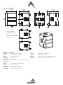
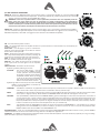
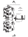
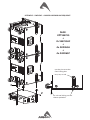
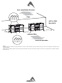
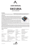
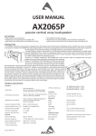
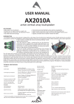
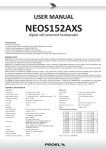
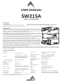
USER MANUAL
SW215A
active subwoofer
KEY FEATURES
• Very High Output
• Compact size for a very good output-to-weight ratio
• Digitally controlled Class D amplifier module with SMPS
• Manifolded Transmission Line configuration for very fast transient response
• 96KHz / 40 bit floating point CORE processing with PRONET remote control
INTRODUCTION
The SW215A subwoofer is designed to deliver high quality low frequency reproduction where very
high output is a key requirement, together with well defined deep bass response and fast transient
response. Its compact size and light weight make it suitable for several different uses, ranging from
touring applications to fixed installations and high-level dance clubs.
The SW215A is a very high quality powered subwoofer system featuring some of the most
advanced technologies for low frequency reproduction. Its unique and innovative design is based
on a configuration that can be defined as Manifolded Transmission Line.
It uses manifolding of the front side of the cones to maximize the mutual coupling between the
two drivers, while loading the back of the cone with a large-size transmission line that has the
function to create a transmission path from the back of the transducers to the front.
The SW215A subwoofer system is equipped with two high power 15” (380mm) transducers
capable of long excursion (up to 33mm peak-to-peak), controlled by high stiffness Double Silicon
Spider as centering suspension and by heavy duty surround. The motor structure features high
strength (BL²/Re) with optimized symmetry and excursion controlled by Aluminium Demodulating
Ring. The robust copper 75mm (3”) voice coil is wounded in two different layers both outside and
inside the coil support, then doubling the coil surface exposed to air cooling and consequently
improving the long term thermal capacity of the loudspeaker. Cones are made of very high-stiffness
reinforced paper, featuring also invisible water repellent treatment.
The SW215A is processed by 40bit, 96kHz floating point CORE DSP and powered by DA SERIES digital power modules, a new generation of CLASS
D power amplifier with digitally-controlled SMPS. The DA module employed for powering the SW215A delivers in an ultra-compact package a
maximum power of 2000W.
TECHNICAL SPECIFICATION
Acoustical
System type
Manifolded Band Pass
Transducer
Two 15” (380 mm), 3” (75 mm) VC,
High stiffness water repellent reinforced
cone, Flux Demodulating Ring VC,
Double Centering Spider Suspension
Frequency response (±3 dB)
Maximum Peak SPL @ 1m
Electrical
Input Impedance
Input Sensitivity
Signal Processing
39 Hz – 100 Hz (Processed)
139 dB
20 kΩ balanced
+4 dBu / 1.25 V
CORE processing, 96kHz / 40bit floating
point SHARC DSP, 24 bit AD/DA converters
Amplifier Type
Class D with Variable Switching Frequency
and SMPS
Mains Voltage Range (Vac)
230 V~ ±15% or 115 V~ ±15% 50/60 Hz
Mains Connector
PowerCon® (NAC3MPA + NAC3MPB)
Consumption*
IN / OUT Connectors
IN / OUT Network Connectors
Mechanical
Width
Height
Depth
Depth Including Wheels
Construction
700 W (nominal) 1700 W (max)
Neutrik XLR-M / XLR-F
ETHERCON® (NE8FAV)
Paint
High resistance, water based paint
4 heavy-load 100 mm ø
4 handles
571 mm (22.48”)
800 mm (31.50”)
582 mm (22.91”)
710 mm (27.95”)
15 mm, reinforced Phenolic Birch
Direct access Controls
4 Presets: Standard, InfraSub, Cardioid,
User. Network Termination, GND Link
Wheels
Transport
Remote Controls
PRONET control software
Side Suspension
High Strength Steel with ¼ Fast Pin (SW215AF)
Back Suspension
Net Weight
High Strength Steel with ¼ Fast Pin (SW215AF)
64.5 Kg (142 lb) SW215A - 68.5 Kg (151 lb) SW215AF
Network protocol
CANBUS
Output Power
1000 W + 1000 W
* Nominal consumption is measured with pink noise with a crest factor of 12
dB, this can be considered a standard music program.
MECHANICAL DRAWING
58.2 cm
22.91"
57.1 cm
22.48"
71.0 cm
27.95"
F
80 cm
31.50"
F
P
F
F
F = flying points available
on SW215AF version only.
F
F
F
P = M20 insert for DHSS10M20
pole adaptor for conventional
SUB-SAT system.
F
F
OPTIONAL ACCESSORIES
NAC3FCA
Neutrik Powercon® BLUE PLUG
AX2065A
Active vertical array loudspeaker
NAC3FCB
Neutrik Powercon® WHITE PLUG
USB2CAN
PRONET network converter
NE8MCB
Neutrik Ethercon PLUG
KPTSW215
Fly bar for Axiom AX2065 and SW215 Loudspeakers
NC3MXXBAG
Neutrik XLR-M
DHSS10M20
Sub-Speaker ø35mm Pole with M20 screw
NC3FXXBAG
Neutrik XLR-F
see www.proel.com for detailed description and other available accessories.
SPARE PARTS
AC103GS
100 mm Swivel castor without brake
AC115DN
Black steel handle
98AXM215SW8
15’’ woofer - 3” VC - 8 ohm
NAC3MPA
Neutrik Powercon® BLUE SOCKET
91AMDSW215
Amplifier module assembly
I/O AND CONTROL OPERATIONS
MAINS IN - Powercon® NAC3FCA power input connector (blue). To switch the amplifier on, insert the Powercon®
connector and turn it clockwise into the ON position. To switch the amplifier off, pull back the switch on the connector
and turn it counter-clockwise into the POWER OFF position.
WARNING! In the case of product failure or fuse replacement, disconnect the unit completely from the
mains power. The power cable must only be connected to a socket corresponding to the specifications
indicated on the amplifier unit. The power supply must be protected by a suitably rated thermo-magnetic
breaker. Preferably use a suitable switch to power on the whole audio system leaving the Powercon® always
connected to each speaker, this simple trick extend the life of the Powercon® connectors.
MAINS OUT - Powercon® NAC3FCB power output connector (grey). This is connected in parallel with the MAINS ~
/ IN. The maximum load applicable depends on the mains voltage. With 230V~ we suggest to link a maximum of 4
SW215A loudspeakers, with 120V~ we suggest to link at maximum of 2 SW215A loudspeaker.
ON - This LED indicates power on status.
PROT - This red LED lights when the amplifier module is in protect mode for an internal fault and, consequently, the
amplifier is muted.
SIGN LIMIT - This LED lights in green to indicate the
presence of the signal and lights in red when an internal
limiter reduces the input level.
INPUT - Audio signal input with locking XLR connector. It
has a fully electronically balanced circuitry including AD
conversion for the best S/N ratio and input headroom.
LINK - A direct connection from the input connector to
link other speakers with same audio signal.
GND LIFT - This switch lift the ground of the balanced
audio inputs from the earth-ground of the amplifier
module.
PRESET BUTTON - This button has two function:
1) Pressing it while powering on the unit:
ID ASSIGN
the internal DSP assigns a new ID
to the unit for the PRONET remote
control operation. Each loudspeaker
must have a unique ID to be visible in
the PRONET network. When you assign
a new ID, all the other loudspeakers
with the ID already assigned must be
ON and connected to the network.
2) Pressing it with the unit ON you can select the DSP
PRESET. The selected PRESET is indicated by
the corresponding LED:
STANDARD
This PRESET is suitable for any application where low frequency reinforcement is required. It features a 90Hz cut off frequency
and it can be used in almost any environment in combination with any vertical arrays.
INFRA
This PRESET can be used when a deeper bass response is required (Note that when this preset is used the sound pressure level
of the system is slightly reduced). NOTE: INFRA and STANDARD PRESET must NOT be used together in close units.
CARDIOID
This special PRESET, combined with the STANDARD PRESET, gives the advantage to reduce the low frequencies at the back of
an array of three subs, in order to obtain a more comfortable level for the performers on the stage without losing level for the
the audience in front of the array. The cardioid configuration is also useful in situation where you want to reduce the bass
frequency feedback due to many microphones on stage, for example for acoustic and jazz ensemble, classic orchestra, musicals.
Further in this manual you can find some example how to set up a cardioid array.
USER
This LED lights when the USER PRESET is loaded. This preset corresponds to USER MEMORY no. 1 of the DSP and, as a factory
setting, it’s the same to STANDARD. If you want to modify it, you have to connect the unit to a PC, edit the parameters with
PRONET software and save the PRESET into USER MEMORY no. 1.
NETWORK IN/OUT - These are a standard RJ45 CAT5 connectors (with optional NEUTRIK NE8MC RJ45 cable connector carrier), used for PRONET
network transmission of remote control data over long distance or multiple unit applications.
TERMINATE - In a PRONET network the last loudspeaker device must be terminated (with an inner load resistance) especially in a long run cabling:
press this switch if you want to terminate the unit.
POWER AMPLIFIERS
The SW215A is powered by DA SERIES digital power modules, a new generation of CLASS D power amplifier with digitally-controlled SMPS.
The innovative technology used for these amplifiers (including also the use of a variable switching frequency) offers performances at the top of
the range, such as a superior sound definition at any audio frequency, very high dynamics also for low level signals and very low distortion even at
the maximum power The superior sound quality can be compared with top-of-the-range AB-class analog systems, while the DA modules feature a
higher dynamics, very compact size and light weight and efficiency above 90%. The two DA modules employed for powering the SW215A deliver
in an ultra-compact package a maximum power of 2000W.
SIGNAL PROCESSING
The system processing is based on the CORE DSP platform, which has been designed by the PROEL R&D Laboratories using one of the most
advanced SHARC DSP for audio application. It features 40bit, 96kHz floating point resolution and high quality 24bit AD/DA converters, for a perfect
signal integrity, a dynamic range in excess of 110dB and a superior sonic performance. Thanks to its massive processing power, the CORE platform
is capable of providing the most sophisticated algorithms for speaker processing, together with remote control and networking capability.
The PRONET control software, working on a solid and reliable CANBUS based network protocol, provides an intuitive interface for the remote
control of the whole system, with the possibility of eqing, delaying, increasing the protections and monitoring the status of the amplifier.
PRONET
PRONET software has been designed by Proel’s Research & Development Department to easily control a single unit or a network of devices, like
active loudspeakers or speaker processors, equipped with the C-AUDIO CORE digital processing platform.
PRONET has been developed in collaboration with sound engineers and sound designers, in order to offer an “easy-to-use” tool to setup and
manage your audio system. With PRONET you can visualize signal levels, monitor internal status and edit all the parameters of each connected
device.
Download the PRONET app from the PROEL website at http://www.proel.com clicking on support / download section.
The SW218A loudspeaker devices can be connected using the network connection, in this case the PROEL USB2CAN converter optional accessory is
needed. The first time you connect a device with the USB2CAN converter, Windows O.S. will ask you to install the driver files, which you can find in
the Driver folder within the Pronet application folder (by default is C:\Program Files\Proel\Pronet\Driver, or if you changed it <your path>\Driver).
Please refer also to “Installation” and “Drivers” paragraphs in the Pronet documentation.
The PRONET NETWORK is based on a robust, reliable and fast communication protocol called CANBUS. The devices in a PRONET NETWORK are
connected together with a “linear bus topology”. The USB2CAN converter must be connected to the network input of the first device, the network
output of the first device is connected to the input of the second and so on. For the network connections simple RJ45 cat.5 or cat.6 ethernet
cables can be used (please don’t confuse a ethernet network with a PRONET network these are completely different and must be fully separated
also both use the same kind of cable).
The beginning and the end of a PRONET NETWORK must be terminated. One side is terminated by the USB2CAN converter, the other side must
be terminated pressing the TERMINATE switch on the last device. All devices between these two points must have the TERMINATE switch lifted.
Assign the ID number
To work properly in a PRONET network each connected device must have a unique identifier number, called ID. By default the USB2CAN PC
controller has ID=0 and there can be only one PC controller. Every other device connected must have its own unique ID equal or greater than 1:
in the network cannot exist two devices with the same ID.
An ID number is assigned automatically to each devices when they are turned on for the first time connected to a network.
In order to correctly assign a new available ID to each device for working properly in a Pronet network, follow these instructions:
1. Switch off all the devices.
2. Connect them correctly to the network cables.
3. “TERMINATE” the latest device in the network connection.
4. Switch on the first device keep pressed “PRESET” button on the control panel.
5. Leaving the previous device switched on, repeat the previous operation on the next device, until the latest device is turned on.
The “Assign ID” procedure for a device makes the internal network controller to perform two operations: reset the current ID; search the first free
ID in the network, starting from ID=1. If no other devices are connected (and powered on), the controller assume ID=1, that is the first free ID,
otherwise it searches the next one left free.
These operations ensure that every device has it’s own unique ID, if you need to add a new device to the network you simply repeat the operation
of step 4. Every device maintains its ID also when it is turned-off, because the identifier is stored in the internal memory and it is cleared only by
another “Assign ID” step, as explained above. This means that if your network is made always of the same devices the assigning ID procedure must
be executed only the first time the system is turned on.
For more detailed instruction about PRONET see the PRONET USER’S MANUAL included with the software.
EXAMPLE OF PRONET NETWORK WITH AX2065A AND SW215A
PC NOTEBOOK
USB2CAN
USB 2.0 port
STATUS
CONVERTER
USB2CAN
CODE:
USB2CAN
S/N:
00001
RATINGS: 5V --- 200mA
RoHS COMPLIANT
MADE IN ITALY
network
not pressed
last device
pressed
AX2065A
AX2065A
AX2065P
AX2065A
AX2065P
network
SW215A
Useful tools to set up properly a vertical array system using the SW215A subwoofer
This is a list of tools that can be very useful to set properly a vertical array system with the SW215A active subwoofers.
CABLE TESTER
It is a good practice to check all cables before each installation, because even one faulty cable can compromise heavily the
system performance.
INCLINOMETER WITH LEVER
This tool can be used to verify the vertical array angle. It can be used at the top or at the bottom of the array In this
case you have to sum all splay angles, so the maximum precision is needed for aiming the vertical array, particularly
for long throw applications.
LASER DISTANCE METER
This instrument can be useful to measure the height of the vertical array and to know the distance between FOH-Subs and FOH-Array
for setting the delay time.
SMAART or similar acoustic measurement system
These are useful to measure delays, phase and response of the system.
PRESET
The SW115A has three factory presets already stored inside the CORE DSP, these preset are ready to use the sub in combination with AX2065A
vertical array loudspeaker or any other professional audio system:
STANDARD PRESET: the response starts at 45Hz and the cutoff is at 100Hz with LR 24dB/oct., use this preset for almost any application at ground
stack and it must be used with the SW215AF set as flown (see FLOWN SET UP).
INFRASUB PRESET: the response starts at 39Hz and the cutoff is at 60Hz with LR 24dB/oct., use this preset when a very deep bass response is
required, it must be used at ground stack only, alone or in combination with some other boxes set as STANDARD, absolutely do not use it in
combination of CARDIOD preset. NOTE: INFRA and STANDARD PRESET must NOT be used together in close units.
CARDIOD PRESET: the response of this preset is the same of STANDARD preset but when combined together as described further the sub stack is
capable to cancel tha bass in the backwards, absolutely it must be used in combiantion of other two boxes and at ground stack.
SW215A - PRESET RESPONSE
INFRA
STANDARD
+15
+10
+5
0
-5
-10
-15
-20
-25
-30
-35
20
50
100
200
500
1K
2K
5K
10K
20K
Hz
AIMING and SUSPENDING INSTRUCTIONS (SW215AF only)
PREDICTION: EASE Focus 2
To aim correctly a complete system we suggests to use always the Aiming Software - EASE Focus 2:
The EASE Focus 2 Aiming Software is a 3D Acoustic Modelling Software that serves for the configuration
and modelling of Line Arrays and conventional speakers close to reality. It only considers the direct
field, created by the complex addition of the sound contributions of the individual loudspeakers or
array components.
The design of EASE Focus is targeted at the end user. It allows the easy and quick prediction of the array
performance in a given venue. The scientific base of EASE Focus stems from EASE, the professional
electro- and room acoustic simulation software developed by AFMG Technologies GmbH. It is based on
the EASE GLL loudspeaker data file required for its use: AXIOM_AX Series_v2_0.GLL, please note that the version must be 2.0 or more. The GLL
file contains the data that defines the Line Array with regard to its possible configurations as well as to its geometrical and acoustical properties.
For detailed explanation of how to use the software and how to obtain a correct aiming refer to EASE Focus documentation and other on-line
manuals (http://focus.afmg.eu/index.php/fc-software-en.html).
WARNING! CAREFULLY READ THE FOLLOWING INSTRUCTIONS AND CONDITION OF USE:
• This loudspeaker is designed exclusively for Professional audio applications. The product must be installed by qualified personal only.
• Proel strongly recommends that this loudspeaker cabinet be suspended taking into consideration all current National, Federal, State and
Local regulations. Please contact the manufacturer for further information.
• Proel do not accept any liability for damage caused to third parties due to improper installation, lack of maintenance, tampering or
improper use of this product, including disregard of acceptable and applicable safety standards.
• During assembly pay attention to the possible risk of crushing. Wear suitable protective clothing. Observe all instructions given on the
rigging components and the loudspeaker cabinets. When chain hoists are in operation ensure that there is nobody directly underneath or
in the vicinity of the load. Do not under any circumstances climb on the array.
FLOWN SET UP (SW215AF only)
Suspending the sub-woofers has different advantages and some incovenient. One incovenient is that it’s not possible to use the cardioid
configuration, while another one is that as the sub-woofers don’t couple with the ground and indoor usage can have different behaviours
depending on ceiling and walls. The advantages are that the space underneath the stage can be free from subs, the coupling between sub and
sat is better and, using a column of 4-6 sub boxes, the basses can be steered more deeply into the audience with a more uniform distribution of
the low frequencies.
The SW215AF subwoofers can be suspended alone or at the top of a vertical array of AX2065A loudspeakers using the KPTSW215 fly bar. The
boxes are linked together in a column using a series of couplers integrated in the frame of each enclosure. Each system can be set properly both
acoustically and mechanically, using the aiming software.
Coupling the system in the front does not require any adjustment: using two locking pins, each loudspeaker box is fixed to the previous. The slotted
bar in the back is inserted in a U-shaped frame that features a series of numbered holes. Sliding the slotted bar in the U-shaped frame of the
next loudspeaker and inserting a locking pin in one of the numbered holes, it is possible to adjust the relative splay angle between two adjacent
loudspeakers in the array column.
KPTSW215 fly bar maximum capacity is 540 Kg (1190 lbs) with the
0° angle. It can support, with a safety factor of 10:1, up to:
• 8 AX2065A + 8 AX2065P (flybar from 0° to 10°)
• 12 AX2065A (flybar from 0 to 10°)
• 2 SW215AF + 4 AX2065A + 4 AX2065P (flybar at 0°)
• 2 SW215AF + 8 AX2065A (flybar at 0°)
• 6 SW215AF (flybar from 0° to 5°)
Follow the sequence in the figure for fixing the fly bar at the first box.
Usually this is the first step before lifting up the system. Be careful to
insert properly all the locking pins (1)(2) and (3)(4) then the shackle
(5) in the right holes as specified by the aiming software.
When lifting the system always proceed gradually step by step,
paying attention to secure the fly bar to the box (and the box to the
other boxes) before pulling up the system: this makes easier to insert
properly the locking pins. Also when the system is released down,
unlock gradually the pins.
During the lifting be very careful to not let the cables enter the space
between one enclosure and the other, as their compression could
cut them.
Please note that the Rear Link Bar of the SW215 cabinet has two
holes (see figure): the hole signed as nr.1 must be used for SW215SW215 sub-sub link, hole signed as nr.2 must be used for SW215AX2065 sub-sat link.
KPTSW215 FLY BAR AND ACCESSORIES
STRAIGHT SHACKLE 16mm
M10 FOOT FOR
STACKED INSTALLATION
(OPTIONAL)
IDENTIFICATION AND
DATA LABEL
FRONT BOX
PIN ATTACHMENT
SUSPEND HOLE
INDICATOR
SUSPEND HOLES
FRONT BOX
PIN ATTACHMENT
REAR BOX
PIN ATTACHMENT
KPTSW215 FLY BAR ASSEMBLY SEQUENCE
2 1
5
1
3
2
4
SW215 REAR LINK BAR
none = rest hole
2 = SW215-AX2065 hole
1 = SW215-SW215 hole
KPTSW215 - SW215AF ARRAY ASSEMBLING SEQUENCE
MAX:
KPTSW215
+
6x SW215AF
use the pin to set the
front linking bar:
rest, sat, or sub
3
2 1
1
for sub-sub linking use the
longer positions
2
4
KPTSW215 - SW215AF - AX2065A ASSEMBLING SEQUENCE
MAX:
KPTSW215
+
2x SW215AF
+
4x AX2065A
+
4x AX2065P
use the pin to set the
front linking bar:
rest, sat, or sub
3
2 1
4
1
2
for sub-sat linking use the
shorter positions
CARDIOID SET UP
The cardioid preset must be used in a sub array of three SW215A. Two box must be oriented towards the audience and one must be turned in the
opposite direction (typically the box in the centre of the array). The bottom and the top boxes must have the STANDARD PRESET, the box in the
middle must have the CARDIOID PRESET. The audio signal sent to all boxes is the same.
The CARDIOID PRESET has the same response of the STANDARD PRESET, but to obtain the maximum cancellation on the back side of the array it
has the phase inverted and a proper level and delay setting.
The figure below shows two typical displacement of the array. The first with all the boxes in horizontal position for a total height of 1713 mm and
a width of 800 mm. The second one with all the boxes in vertical position for a total height of 800 mm and a width of 1713 mm.
bass cancellation direction
stage
wall or other
big ostacle
80 cm min.
2.7 ft min.
80 cm min.
2.7 ft min.
120 cm min.
3.9 ft min.
audience floor
bass sum direction
NOTES:
When placing the cardioid array keep a distance to walls or other obstacles of at least 80 cm (2.6 ft) in order not to affect the radiation of the
reversed cabinet.
When placing multiple cardioid arrays keep a distance between them of at least 120 cm (3.9 ft) in order not to maximize the combined radiation
of whole arrays.
bass cancellation direction
stage
wall or other
big ostacle
80 cm min.
2.7 ft min.
80 cm min.
2.7 ft min.
80 cm min.
2.7 ft min.
audience floor
bass sum direction
NOTES:
When placing the cardioid array keep a distance to walls or other obstacles of at least 80 cm (2.6 ft) in order not to affect the radiation of the
reversed cabinet.
When placing multiple cardioid arrays keep a distance between them of at least 80 cm (2.6 ft) in order not to maximize the combined radiation
of whole arrays.
LIMITED WARRANTY
Proel warrants all materials, workmanship and proper operation of this product for a period of two years from the original date of purchase. If any defects are found
in the materials or workmanship or if the product fails to function properly during the applicable warranty period, the owner should inform about these defects the
dealer or the distributor, providing receipt or invoice of date of purchase and defect detailed description. This warranty does not extend to damage resulting from
improper installation, misuse, neglect or abuse. Proel S.p.A. will verify damage on returned units, and when the unit has been properly used and warranty is still
valid, then the unit will be replaced or repaired. Proel S.p.A. is not responsible for any “direct damage” or “indirect damage” caused by product defectiveness.
• This unit package has been submitted to ISTA 1A integrity tests. We suggest you control the unit conditions immediately after unpacking it.
• If any damage is found, immediately advise the dealer. Keep all unit packaging parts to allow inspection.
• Proel is not responsible for any damage that occurs during shipment.
• Products are sold “delivered ex warehouse” and shipment is at charge and risk of the buyer.
• Possible damages to unit should be immediately notified to forwarder. Each complaint for package tampered with should be done within eight days from product
receipt.
SAFETY INSTRUCTIONS
– To reduce the risk, close supervision is necessary when the product is used near children.
– Protect the apparatus from atmospheric agents and keep it away from water, rain and high humidity places.
– This product should be site away from heat sources such as radiators, lamps and any other device that generate heat.
– This product should be located so that its location or position does not interfere with its proper ventilation and heating dissipation.
– Care should be taken so that objects and liquids do not go inside the product.
– The product should be connected to a power supply mains line only of the type described on the operating instructions or as marked on the product. Connect the
apparatus to a power supply using only power cord included making always sure it is in good conditions.
– WARNING: The mains plug is used as disconnect device, the disconnect device shall remain readily operable.
– Do not cancel the safety feature assured by means of a polarized line plug (one blade wider than the other) or with a earth connection.
– Make sure that power supply mains line has a proper earth connection.
– Power supply cord should be unplugged from the outlet during strong thunderstorm or when left unused for a long period of time.
CE CONFORMITY
Proel products comply with directive 2004/108/EC (EMC), as stated in EN 55103-1 and EN 55103-2 standards and with directive 2006/95/CE (LVD), as stated in EN
60065 standard.
PROEL S.p.A. (World Headquarter) - Via alla Ruenia 37/43 - 64027 Sant’Omero (Te) - ITALY
Tel: +39 0861 81241 Fax: +39 0861 887862 www.proel.com