1
PC Version
User's Manual
for
Microtek Scanners
and the
ScanWizard Scanning Software
Copyright © 1997 Microtek Lab, Inc.
All rights reserved.
Doc. No. M-9142812920-2
Second Edition: August 1997
Microtek Lab, Inc.
3715 Doolittle Drive, Redondo Beach, CA 90278-1226
Main: (310) 297-5000
Sales: 800-654-4160
Tech Support: (310) 297-5100
Fax: (310) 297-5050
BBS: (310) 297-5102
AutoTech fax back: (310) 297-5101
Internet: http://www.microtekusa.com
Tech Support Web Page: http://www.support.microtek.com
Microtek International, Inc.
6, Industry East Road 3
Science Based Industrial Park
Hsinchu 30077, Taiwan, R.O.C.
Tel: 886-3-5772155Fax: 886-3-5772598
Worldwide Web Site: http://www.microtek.tw
Microtek Europe BV
Max Euwelaan 68
NL - 3062 MA Rotterdam
The Netherlands
Tel: 31-10-242-5688
Fax: 31-10-242-5699
Worldwide Web Site: http://www.microtek.nl
To obtain optimal results from the Microtek scanning software and user's guide, you
should be familiar with such Windows concepts as pointing, clicking, dragging, and
selecting from menus and dialog boxes. If these things are new to you, refer to your
Microsoft Windows User’s Guide. Windows is a trademark of Microsoft Corporation.
Adobe Photoshop is a trademark of Adobe Systems, Inc. All other product names are
trademarks or registered trademarks of their respective holders.
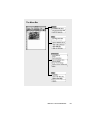
Table of Contents
Chapter 1 Basic Concepts.............................................. 1-1
What is a Scanner .............................................................................................
How scanners work ...................................................................................
Components of effective scanning ............................................................
Image Types ......................................................................................................
Single-bit ...................................................................................................
Grayscale ...................................................................................................
Color ..........................................................................................................
Selecting an image type .............................................................................
Text Scanning ...................................................................................................
Getting the Best Results ...................................................................................
Resolution..................................................................................................
1-2
1-3
1-4
1-5
1-5
1-6
1-6
1-7
1-7
1-8
1-9
Choosing the best resolution setting ................................................................ 1-9
When to use high resolution .......................................................................... 1-11
When to use interpolated resolution .............................................................. 1-11
Scaling .....................................................................................................
Dynamic range ........................................................................................
Color calibration and correction ..............................................................
Image enhancement .................................................................................
1-12
1-12
1-13
1-14
Brightness, Contrast and Exposure ............................................................... 1-14
Shadows and Highlights ................................................................................ 1-15
Curve ............................................................................................................. 1-15
Filters ............................................................................................................. 1-16
Auto ............................................................................................................... 1-16
Tints ............................................................................................................... 1-16
Color Correction / DCR ................................................................................ 1-16
File formats .............................................................................................
Storage requirements ...............................................................................
Selecting the printing method .................................................................
Quick Tips for Best Scans ..............................................................................
1-17
1-18
1-19
1-20
Chapter 2 Hardware Installation .................................... 2-1
Installing the scanner ........................................................................................
Voltage .......................................................................................................
Operating the scanner .......................................................................................
Using scanner accessories ................................................................................
Returning scanners for repair ...........................................................................
Locking the scanner carriage ............................................................................
2-2
2-2
2-3
2-4
2-5
2-6
Locking models with a screw-type lock ......................................................... 2-6
Locking models with a latch-type lock ........................................................... 2-7
Replacing the scanner lamp .............................................................................. 2-8
Table of Contents
i
Chapter 3 Software Installation .................................... 3-1
Chapter 4 Sample Scanning .......................................... 4-1
Overview........................................................................................................... 4-2
Scanning a single-bit image .............................................................................. 4-4
Scanning a grayscale image .............................................................................. 4-5
Scanning a color image .................................................................................... 4-6
Enlarging the view of an image ........................................................................ 4-7
Enhancing images ............................................................................................. 4-8
Using the Advanced Image Enhancer dialog box ............................................. 4-9
Important scanning notes ................................................................................ 4-10
Color Plates
Auto and Color Correction controls .................................................................... A
Brightness and Contrast ....................................................................................... B
Saturation and Exposure ...................................................................................... C
Shadows and Highlights ...................................................................................... D
Curve ................................................................................................................... E
Tints ......................................................................................................................F
Filters ................................................................................................................... G
Descreen .............................................................................................................. H
Chapter 5 Reference ...................................................... 5-1
Overview........................................................................................................... 5-2
ScanWizard for Windows ................................................................................. 5-3
The Preview Window ....................................................................................... 5-4
Elements of the Preview window .............................................................. 5-4
The Menu Bar ............................................................................................ 5-5
The Scanner Menu .................................................................................... 5-6
Scanner Model ................................................................................................. 5-6
Get Current Scanner Info ................................................................................ 5-6
Get SCSI Chain ............................................................................................... 5-7
Exiting ScanWizard ................................................................................... 5-8
The View Menu ......................................................................................... 5-9
Full Page Preview ............................................................................................ 5-9
Zoomed Preview ............................................................................................ 5-11
Resize Window to Fit .................................................................................... 5-12
Show / Hide commands ................................................................................. 5-13
The Preferences Menu ............................................................................. 5-14
Scan Material ................................................................................................. 5-14
The Scan Material Status icon ....................................................................... 5-15
Invert ............................................................................................................. 5-17
Horizontal Mirror .......................................................................................... 5-18
Cursor Auxiliary Lines .................................................................................. 5-19
Preview Setup ................................................................................................ 5-21
Live Prevew ............................................................................................... 5-21
Color Preview ............................................................................................ 5-21
Fast Preview .............................................................................................. 5-21
The Preview Area ...................................................................................... 5-22
ii
Microtek User's Guide for Windows
Keep Preview Image ..................................................................................... 5-23
Smoked Glass Background ........................................................................... 5-24
How Smoked Glass works with image enhancement ................................. 5-25
More .............................................................................................................. 5-26
The Help Menu........................................................................................ 5-27
About ............................................................................................................. 5-27
The Tool Buttons ..................................................................................... 5-28
Zoom Preview tool ........................................................................................ 5-29
Scan Frame tool ............................................................................................. 5-30
Magnifying Lens tool .................................................................................... 5-32
Pane tool ........................................................................................................ 5-33
Color Picker tool (Set Shadow / Highlight) .................................................. 5-34
Action buttons ......................................................................................... 5-36
Rulers ...................................................................................................... 5-37
Preview Area ........................................................................................... 5-38
The Settings Window ..................................................................................... 5-39
Elements of the Settings window ............................................................ 5-39
Output Image Parameters ........................................................................ 5-40
Type (Image Type or Scan Mode) ................................................................. 5-40
Halftone Patterns ...................................................................................... 5-41
Resolution ...................................................................................................... 5-42
Unit Selection ............................................................................................ 5-43
Image Dimension controls ...................................................................... 5-44
How to use the Input-Output dimensions ...................................................... 5-45
How to use the Aspect Lock .......................................................................... 5-46
Scaling ........................................................................................................... 5-47
Image Adjustment controls ...................................................................... 5-48
Auto (Automatic Contrast Control) ............................................................... 5-48
Color Correction / DCR ................................................................................ 5-50
Image-Enhancement Tools ...................................................................... 5-51
What the Image Enhancement tools are ........................................................ 5-52
Using the Advanced Image Enhancer dialog box ......................................... 5-53
The Action Buttons in the AIE dialog box .................................................... 5-54
Brightness, Contrast and Exposure tool ........................................................ 5-55
The BCE screen (for grayscale and color) ................................................ 5-56
The BCE screen (for line art) .................................................................... 5-57
How to use the BCE tool ........................................................................... 5-58
Tints tool ........................................................................................................ 5-59
The Tints screen ......................................................................................... 5-60
How to use the Tints tool ........................................................................... 5-61
Shadows and Highlights tool ......................................................................... 5-62
The Shadows and Highlights screen .......................................................... 5-63
How to read and correct a histogram ........................................................ 5-65
How to use the Shadows and Highlights tool ............................................ 5-66
Curve tool ...................................................................................................... 5-67
How to read the curve ............................................................................... 5-67
Sample images and their curves ................................................................ 5-68
The Curve screen ....................................................................................... 5-69
Using the curve buttons ............................................................................. 5-70
How to use the Curve tool ......................................................................... 5-71
Table of Contents
iii
Chapter 5 (cont).
Filters tool ...................................................................................................... 5-72
Blur filters .................................................................................................. 5-73
Sharpen filters ........................................................................................... 5-73
Edge Enhancement filter ........................................................................... 5-74
Emboss filter .............................................................................................. 5-74
Unsharp Masking ...................................................................................... 5-75
More Options tool ......................................................................................... 5-76
Velocity ...................................................................................................... 5-77
Scan Quality .............................................................................................. 5-78
Gray Scan CCD Filter ............................................................................... 5-78
Descreen .................................................................................................... 5-79
The Window Expansion button ............................................................... 5-80
The Information Window ...............................................................................
Elements of the Information window ......................................................
Using the Zoom Level Display ...............................................................
Using the Cursor Locator ........................................................................
Using the Color Meter Display ...............................................................
Using the Sample Size button .................................................................
5-81
5-81
5-82
5-82
5-83
5-85
Value and Percent .......................................................................................... 5-85
Sample Size Options ..................................................................................... 5-86
Using the Pixel Display ........................................................................... 5-86
The Scan Job Window ....................................................................................
Elements of the Scan Job window ...........................................................
How to read the Scan Job window ..........................................................
The New button .......................................................................................
5-87
5-87
5-88
5-89
More Applications ......................................................................................... 5-93
The Duplicate button ...............................................................................
The Save button .......................................................................................
The Add button ........................................................................................
The Check button ....................................................................................
The Delete button ....................................................................................
The Up/Down Position Arrows ...............................................................
5-94
5-96
5-96
5-96
5-97
5-97
Appendix .......................................................................... A-1
Product and Technical Support .........................................................................A-2
Troubleshooting ................................................................................................ B-1
Glossary ............................................................................................................ C-1
iv
Microtek User's Guide for Windows
1
Basic Concepts
This chapter covers basic scanning concepts. If you already
have basic scanning knowledge, you may skip this section
and go directly to Chapter 2 for hardware installation.The
following subjects are covered here:
• What is a scanner
• How scanners work
• Components of effective scanning
• Image types
• Text scanning
• Resolution and scaling
• Dynamic range and color calibration
• Image enhancement
• File formats and storage
• Printing
• Quick tips for best scans
What is a Scanner
A scanner is a device that captures an image and converts it into a
digital form that your computer can display, edit, store, and output. The
image may be a photograph, page of text, drawing or illustration, or
even a relatively flat, three-dimensional object such as a bolt of fabric.
In practice, this means you can use your scanner to do the following:
• Incorporate artwork or photos
into documents
• Scan printed text into your
word processor and eliminate
retyping
• Scan faxed documents into a
database or word processor
• Add images to multimedia
productions
• Integrate visuals into presentations to make them communicate more effectively.
With a basic understanding of how scanners work, the types of scanners
available, and what they are capable of doing, you can improve the
quality and efficiency of your work.
Types of scanners
Scanners can be classified into two general types:
•
Flatbed scanners, which are used to scan photographs or prints.
Flatbeds have a glass surface on which the materials to be scanned
are placed. An example of a Microtek flatbed is the ScanMaker III.
•
1-2
Slide scanners, which are used to scan transparent materials such
as 35-mm slides. The ScanMaker 35t Plus is an example of a slide
scanner.
Microtek User's Guide for Windows
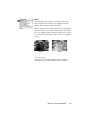
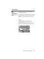
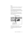
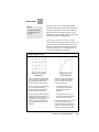
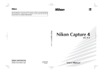
How scanners work
Scanners capture images by
shining light onto the
document to be scanned. The
light then bounces back and
is captured by a strip of lightsensitive cells called a
charge-coupled device, or
CCD.
Since dark areas on the paper
reflect less light and light
areas of the paper reflect
more light, the CCD is able
to detect the amount of light
reflecting from each area of
the image. The CCD then
converts the reflected light
waves into digital information, represented by combinations of ones and zeros
(called bits, for binary digits).
The process above describes
how scanners scan an opaque
original, such as a photographic print or page of text.
The same principle works if
you scan a transparency instead
of an opaque document, but
instead of bouncing back, the
light passes through the
transparency and is captured by
the CCD. Scanning a transparency involves special lighting
considerations, so a scanner
accessory called a Transparent
Media Adapter is specifically
used for this purpose.
Finally, the scanning software
that controls the operation of
the scanner reads this
incoming data and reconstructs it into a computer
image file.
Basic Concepts
1-3
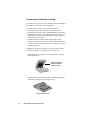
Components of effective scanning
The scanner is only one part of the scanning system. In addition to
the scanner, you need these other components:
• A SCSI cable to connect your scanner and computer
• Scanning software that controls how the scanner works
• Image-editing software (such as Adobe Photoshop or Microtek
ImageStar II) to integrate scanned images into your work; or an
OCR software (such as Caere OmniPage Direct) to integrate
scanned text into your work
• A suitable monitor to display color and grayscale images
• A device for outputting your work, such as a black and white or
color laser printer, dye sublimation printer, imagesetter or other
color proofing device.
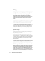
In addition to the basic components, you can use these scanner
accessories to make your scanning even more effective:
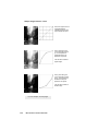
• Transparent Media Adapter: For scanning slides, filmstrips,
and transparencies.
Transparent Media
Adapter attached to
a flatbed scanner
• Auto Document Feeder: Helps with text scanning by allowing
continuous scanning of up to 50 pages of text.
Auto Document Feeder
1-4
Microtek User's Guide for Windows
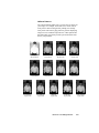
Image Types
For a computer to represent image information in a digital format,
the computer uses units of picture elements, or pixels.
An image file, for instance, is simply a representation of hundreds, thousands, or even millions of pixels arranged in a grid, and
computers record the intensity and color of a pixel in 1 or more
bits of data. The greater the number of bits, or bit-depth, of an
image, the more information it can store. For easy classification,
images can be categorized into single-bit, grayscale, or color.
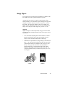
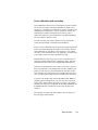
Single-bit
Single-bit images are the simplest kind, using just one bit of data
to record each pixel. Single-bit images come in two types: line art,
and halftone.
•
Line Art includes anything that is black and white, such as a
pencil or ink sketch. Line Art may also include one-color
images, such as mechanical blueprints or drawings.
•
Halftones are reproductions of images that give the illusion of
gray — but only because the black and white dots (or pixels)
comprising the image are arranged in such a way as to fool
the eye to see gray. This is because when the halftone is
printed, dark areas are represented by many dots coming
together, while lighter areas are those with fewer dots. An
example of halftone images would be the pictures you see in
a newspaper.
Line Art
Halftone
Basic Concepts
1-5
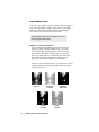
Grayscale
Grayscale images contain more than just black and white, and
include actual shades of gray. In a grayscale image, each pixel or
dot has more bits of information encoded in it, allowing more
shades to be recorded and shown.
For instance, four bits are needed to reproduce up to 16 levels of
gray. Going higher, eight bits can reproduce the 256 levels of gray
required to represent most black-and-white photos accurately.
16 grays
256 grays
Color
Color images contain the most complex information. To capture
color images, scanners use a process based on the RGB (Red,
Green, and Blue) color model, where every color is composed of
a varying amount of the three colors. In the RGB model, the
absence of white light creates black, the complete saturation of
light creates white (100% of red, green, and blue), and equal
amounts of red, green, and blue create intermediate shades of
gray.
Depending on the type of scanner you have, your scanner can
record 24 bits or 36 bits for the three RGB channels. This means
your scanner can record and reproduce an enormous amount of
color information — anywhere from 16.7 million colors for 24bit scanners, to 68.7 billion colors for 36-bit scanners. The extra
amount of information that can be processed by 36-bit scanners
translates to more vivid color reproduction, as the scanner is able
to accommodate more subtle gradations of color approaching
lifelike accuracy.
1-6
Microtek User's Guide for Windows
Selecting an image type
Depending on the scanner you have, you will be able to scan
different types of images according to your needs. You can scan
an image and output it in its original form, or you can output it in
another form and get some interesting effects.
For instance, you can scan a grayscale photo and output it in its
original form as a grayscale photo, or you can output it as a
halftone to create a new look. Whatever you do, however, keep in
mind that the quality of the original is very important in determining the quality of the final scanned image. The next few pages will
give you more information on how to get top-quality scans.
Text Scanning
Aside from scanning images, your scanner can scan text and
deliver it into your word processor, eliminating the need for
retyping. This is done through the use of Optical Character
Recognition (OCR) software, which converts scans to text and
retains text formats through the software's ability to recognize
the shapes, shades and lines that make up individual characters.
Most Microtek scanners come with OCR software to provide you
with maximum value for your scanner.
Basic Concepts
1-7
Getting the Best Results
Scanning is an easy process: You simply put the image to be
scanned on your scanner, run your scanning software, and click on
the Scan button. The image is then delivered to your imageediting software, where it can be stored as a file.
For you to get the best results from your scans, however, it helps
to be aware of variables that affect the quality of your scanning.
This section discusses some of the most important factors affecting scanning, including the following:
• Resolution
• Color calibration
• Image enhancement
• File formats
• File storage and requirements
• Selecting your printing method
1-8
Microtek User's Guide for Windows
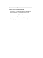
Resolution
Resolution determines the level of detail recorded by the scanner,
and is measured in dots per inch (dpi). The greater the dpi
number, the higher the resolution and the resulting file size.
Image quality improves with higher resolution, but only up to a
certain point, after which increasing resolution simply makes file
sizes unmanageable without yielding any visible improvement to
the image. For most applications, scans of up to 300 dpi are
adequate.
When dealing with resolution, it's important to distinguish
between optical, or true, resolution, and interpolated resolution,
which is resolution enhanced through software.
•
Optical resolution is the key factor in determining the
sharpness and clarity of an image.
•
Interpolated resolution, or resolution enhanced through
software, is useful for certain tasks, such as scanning line art
or enlarging small originals.
Choosing the best resolution setting
Scanning at a higher resolution requires more time, memory, and
disk space. When choosing a resolution setting, consider the type
of image you're scanning and the printing method. Printed images
have their own resolution, as measured in lines per inch (lpi),
which is distinct from the resolution of electronic images (as
measured in dpi).
An easy way to determine the best resolution for your intended
output is to find out the lines per inch (lpi) capability of your
output device and multiply it by 1.5 to 2.0.
For instance, to tailor your scanned image to a typical magazine
printing press that prints at 133 lines per inch, multiply 133 x 1.5
or 2.0, which gives 199.5 or 266. In this case, the optimal
resolution setting for your image would then be 200 dpi to 266
dpi (depending on how high the output quality will be). Lpi
varies, depending on the quality of the printing job. A newspaper
uses approximately 85 lpi, magazines from 133 to 150 lpi, and
fine art books may go as high as 200 to 300 lpi.
If you're outputting images to a monitor (such as doing multimedia work), you need not scan images higher than 72 dpi, as
monitors are capable of only showing images up to 72 dpi. A
higher-resolution image will not be any clearer on the monitor
and will simply create larger files.
Basic Concepts
1-9
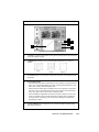
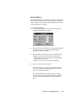
The table below shows optimal resolution settings for most needs. MPR below
stands for "Match Printer's Resolution."
Output Device
Line Art
Grayscale
Color
Black & white
laser printer
MPR
75 dpi
75 dpi
Color desk jet, ink jet,
thermal printer
MPR
100-150 dpi
100-150 dpi
Color dye-sublimation
printer
MPR
MPR
MPR
Printing press or
imagesetter
MPR
150-300 dpi
150-3200 dpi
Remember that the higher the resolution, the larger your image
file will be. For instance, an 8.5" x 11" color photograph scanned
at 75 dpi takes up about 1.6 megabytes (MB). Doubling resolution to 150 dpi will increase the file size four times — to approximately 6.3MB! Going to 300 dpi will increase file size to
26.2MB.
What you need to do then is to select the lowest possible resolution that still gives you good image quality in order to keep file
sizes manageable.
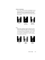
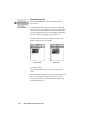
Comparison of images at different resolutions
150 dpi
300 dpi
The two images were scanned at different resolutions, but
there isn't much difference in the printed result. This is because
all printers and presses have their own maximum resolution.
It's also because the final size is so small that anything over
150 dpi is really unnecessary.
1-10
Microtek User's Guide for Windows
When to use high resolution
High resolution is important if you're processing an image
through a high-end color system that carries continuous tone data
from the scanner through the final film output. This is because
high resolution can improve the sharpness and clarity of the dots
that make up the image.
When to use interpolated resolution
Interpolated resolution is useful for scanning line art or enlarging
small originals.
•
For line art: Set the resolution equal to that of your output
device. For instance, if you're producing line art to be printed
by a 1200-dpi imagesetter, you can interpolate resolution to
up to 1200 dpi for superior results. This will produce
smoother lines and eliminate some of the jaggedness
characteristic of line art scans.
•
For enlarging small originals: Let's assume that you scan a
1" x 2" photograph at 300 dpi, and that your maximum
optical resolution is 300 dpi too. To enlarge the image to two
times the original size without loss of detail, interpolate the
resolution to 600 dpi. This way, the image retains clarity and
sharpness even if the print size was doubled.
Basic Concepts
1-11
Scaling
Scaling is the process of creating larger or smaller images in your
scanning software so that you need not resize the images later
when they are delivered to your image-editing program.
In the scanning software, scaling has an inverse relation to
resolution: The lower the resolution, the larger the image can be
scaled. At the highest resolution, images can only be scaled
smaller.
To illustrate the use of scaling, assume you scanned a 2" x 2" image at
300 dpi. To double image size to 4" x 4" without loss of detail,
increase scaling to 200% and maintain resolution at 300 dpi.
This is the same as scanning the image at 600 dpi at 100% scaling
— and then using your image-editing software to enlarge the
output. In the example above, image size was doubled through
scaling alone without having to use the image-editing software.
Dynamic range
Another important factor in obtaining quality scanned images is
the dynamic range of a scanner.
Dynamic range is the ability of the scanner to register a wide
range of tonal values — something from near white to near black.
A scanner with a good dynamic range is able to map input shades
correctly to the output shades, so you will be able to see more
detail in an image.
A scanner with poor dynamic range, on the other hand, will not be
able to detect as wide a range of tonal values. In this case, the
scanner will fill in the shadow areas or lose all detail in the
highlight in an attempt to map the colors correctly. What emerges
will be an image with less detail.
Microtek scanners have a dynamic range capable of registering a
wide palette of tones and translate these accordingly into photorealistic color. For instance, the ScanMaker III, Microtek's 36-bit
scanner, has a dynamic range of 3.4. (For comparison purposes,
anything above 2.0 is good, and anything above 3.0 is impressive.)
1-12
Microtek User's Guide for Windows
Color calibration and correction
Color calibration is the process of ensuring the accurate reproduction of color for images. Full color calibration is usually a twostep process: calibrating your input device, such as a scanner; and
calibrating your output device, such as a printer or monitor. By
calibrating your input and output devices correctly, color is
captured accurately by your scanner and is reproduced faithfully
on your monitor or printer as well.
To make sure that your scanner captures color accurately, Microtek developed DCR, or Dynamic Color Rendition.
DCR is a color calibration and correction system that compensates
for the color shifts that occur invariably in all scanners. Because
each scanner has its own unique "color signature," (one scanner
sees red as "red" and another sees it as "magenta"), it makes sense
to use DCR to ensure accurate reproduction of color.
Without DCR, the only way to correct color would be to do it in
your image-editing software after scanning the image, and postscanning color correction can be a lengthy and tedious process.
This does not mean that the colors will be correct once you print
them; you still need a color management system to calibrate your
printer as well. However, DCR eliminates the inaccuracies that
come from the first round of the color reproduction process and
saves you time from having to do post-scanning color correction.
A generic color profile ships with the ScanWizard for Windows
scanning software which allows you to use the color correction
feature, but in order to make the results even better, you should
calibrate your scanner by using DCR. DCR comes standard on the
ScanMaker III and is available as an option for all other color
scanners.
For examples of images with and without Color Correction, see
the color pages in this manual.
Basic Concepts
1-13
Image enhancement
Several tools are available with your scanning software for adjusting the color and quality of images. Some of these tools include:
Brightness, Contrast and Exposure; Shadows and Highlights;
Curve; Filters; Tints; Auto; and Color Correction.
To see examples of how each tool works in color, see
the color pages in this manual.
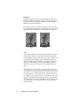
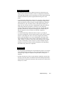
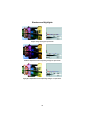
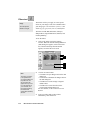
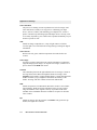
Brightness, Contrast and Exposure
This tool changes the brightness and contrast of the entire
image. An image with high contrast has less gray shades
between black and white and appears to have less visible
detail. On the other hand, an image with low contrast has
more gray shades, has more visible detail, yet tends to look
flat. Contrast determines the number of shades you get;
brightness determines the intensity of those shades.
Exposure, on the other hand, allows you to increase or reduce
available light to the image and may help more image detail
emerge in the process.
Original
Brightness
increased
Contrast
increased
1-14
Microtek User's Guide for Windows
Brightness
decreased
Contrast
decreased
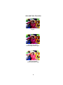
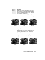
Shadows and Highlights
This tool lets you adjust the shadow and highlight areas of an
image, allowing you to select a new shadow point to become
the darkest value, or a new highlight point to become the
lightest value. The effect of this is to bring out more visible
detail in an image, especially if it has only a limited range of
grays or colors.
Original
Shadows
emphasized
Highlights
emphasized
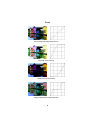
Curve
This tool lets you modify the gamma, which is the contrast
affecting the middle range of grays in an image. The Curve
tool lets you modify the midrange of grays without dramatically altering the shadows and highlights. Using a combination of the Shadows and Highlights tool together with the
Curve tool gives you the most precise control for adjusting
the tonal values of your image.
Original
Grays
lightened
Grays
darkened
Basic Concepts
1-15
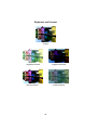
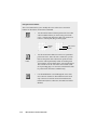
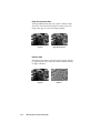
Filters
The Filters tool lets you apply or create special effects to your
images. The filters include Blur, Blur More, Sharpen, Sharpen
More, Edge Enhancement, and Emboss. Below is an example.
Original
Blur
Auto (Automatic Contrast Control)
This tool optimizes the contrast of scanned images by
adjusting the gamma and shadow/highlight values. This is one
of the simplest tools to use, requiring only the click of a
button. It can have the most dramatic effect on your image,
and its results are immediately visible.
Original
Auto applied
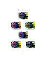
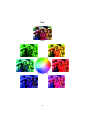
For Color Images only
Tints
This tool lets you adjust the hue and saturation of an image.
The hue of an image is what distinguishes a color from
another (whether it is red, green, blue, etc.), while saturation
refers to the intensity of the color (more red, more green).
Color Correction / DCR
This tool applies a generic color profile to your images to
give it accurate, lifelike color. If you have Microtek's DCR
color calibration and correction system installed, the Color
Correction button will override the generic color profile
embedded in your scanning software and apply DCR instead
to the image.
1-16
Microtek User's Guide for Windows
File formats
You will generally save your scanned images as graphic files.
Several graphic file formats are available for use, and each file
format has its own advantages and disadvantages.
To get the best scans, be familiar with the pros and cons of
each file format and how they are compatible with your
image-editing software and printing equipment.
File format
Description
TIFF
Short for Tagged Image File Format, probably the
most popular format. Adept at storing bitmaps in
many different resolutions, color models, and
compression types, and supported by many commercial applications.
Use the TIFF format whenever possible , since this is
the most widely used.
EPS
Short for Encapsulated PostScript. Good for storing
vector drawings, but not for line art. Ideal for print
applications because it offers more control when
printing to a PostScript printer.
PSP
Adobe Photoshop's internal image format.
GIF
A format used to store images with 256 colors or 256
shades of gray. Mostly used by BBS services and
some low-end graphic applications.
JPEG
A compression algorithm used to store large color or
grayscale files. Some versions of this compression
format may result in minor degradation of image
quality.
PCX
Developed by Z-Soft for use in various paint programs. Also suitable for scanned images and is
widely supported for PC use.
Basic Concepts
1-17
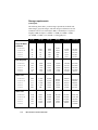
Storage requirements
(in kilobytes)
The following chart shows you the storage requirements for black-andwhite images, grayscale images, and color images in different sizes and
resolutions. All sizes are in kilobytes (KB); 1,000 kilobytes is equal to 1
megabyte (MB). Example: 1,028KB = 1.02MB; 65,742KB = 65MB;
131,484KB = 131MB; 1,577,813KB = 1.5GB (gigabytes).
75 dpi
150 dpi
300 dpi
600 dpi
1200 dpi
65
33
25
14
11
257
130
97
55
42
1028
514
385
220
165
4,109
2,055
1,540
880
660
16,435
8,218
6,153
3,516
2,637
65,742
32,872
24,010
14,063
10,547
514
257
193
110
83
2,055
1,028
770
440
330
8,218
4,109
3,077
1,758
1,319
32,872
16,436
12,305
7,032
5,274
131,484
65,743
49,219
28,125
21,095
825,938
262,969
196,875
112,500
84,375
1,541
771
577
330
248
6,164
3,082
2,308
1,319
989
24,654
12,327
9,229
5,274
3,955
98,614
49,307
36,915
21,094
15,820
394,453
197,227
147,657
84,375
63,282
1,577,813
788,907
590,625
337,500
253,125
2,311
1,156
865
495
371
9,245
4,623
3,461
1,978
1,484
36,980
18,490
13,843
7,910
5,933
147,920
73,960
55,371
31,641
23,731
591,680
295,840
221,485
126,563
94,922
2,366,719
1,183,360
885,938
506,250
379,688
2400 dpi
Single-bit Blackand-White
8.5" x 11"
8.5" x 5.5"
5" x 7"
4" x 5"
3" x 5"
8-bit Grayscale
8.5" x 11"
8.5" x 5.5"
5" x 7"
4" x 5"
3" x 5"
24-bit Color
8.5" x 11"
8.5" x 5.5"
5" x 7"
4" x 5"
3" x 5"
36-bit Color
8.5" x 11"
8.5" x 5.5"
5" x 7"
4" x 5"
3" x 5"
1-18
Microtek User's Guide for Windows
Selecting the printing method
Scanned images can be printed on a variety of devices. Here are
some of the most common ones:
•
Black and white printers (laser, ink jet, dot matrix) are
suitable for producing text and line art, but they are not as
good for printing grayscale images. You can use these printers
to reproduce photographs for FPO (For Position Only)
purposes, as when you need to show a draft of how a document is laid out.
•
Ink jet and desk jet color printers can produce color or
grayscale images that may range in quality from coarse to
medium. Such printers work well for small quantities of color
images or for proofs of images that will be printed later on a
printing press. These printers usually print 256 colors or 256
shades of gray but do not register colors as well. Images
usually end up slightly coarse or washed out.
•
Dye-sublimation color printers print images in photo-realistic
color. Use these printers to print color images with continuous
tone for small print jobs or for proofs of large print jobs that
will be done later on an imagesetter.
•
Printing presses can produce work of high quality. For these
types of printers, you can scan your images and then send the
files to a service bureau or printing company, which typically
uses a high-resolution imagesetter and can print high-quality
text and grayscale images. If you are producing full-color
images, scan them in color, then use your image-editing
software to create the color separation files needed to print
color on a printing press.
Basic Concepts
1-19
Quick Tips for Best Scans
Whenever you scan, keep some goals in mind. How do you want
the final scanned image to look? Where will it be used? What
image-editing software will you use? How will the image be
reproduced, on what type of printer and what type of paper?
With these goals in mind, you can then proceed to obtain quality
scans. Here are a few tips to consider to obtain the best scans.
Get the necessary hardware
Make sure your scanner matches your scanning needs. A 36-bit
scanner will produce superior color and grayscale results to scans
made by a 24-bit scanner. For example, setting a 36-bit scanner to
the scan mode Millions of colors will produce a far better 24-bit
image than if a 24-bit scanner used the same Millions of colors
setting.
In addition, take note of the following:
•
Make sure you have enough RAM and available storage
space in your computer. Scanned images need more memory
than text files, so you may need to add RAM and storage
options. 16MB of RAM is adequate, but more RAM will
speed up your processing.
•
Check if your video card and monitor support the resolutions
you need to display high-quality images. For optimal quality,
use a 24-bit (also known as True Color) card that is set to
"millions of colors" or "16.7 million colors."
Use a good original
A good original is still important in determining the final quality
of the scanned image. Even if your scanning software or imageediting package has tools to improve image quality, they work
only up to a point. Images that are out of focus, dirty, or poorly
exposed may never look great — no matter how much time you
spend retouching them.
Also, do not use halftoned images or images that have been
printed, such as those taken from a magazine. If you scan such
pictures, you will obtain something called a moiré, which is an
undesirable pattern in color printing. Even though the ScanWizard
software has a feature for removing moirés, it's better to start out
with a clear original in the first place. (For more information on
moirés and to see what they look like, see the color pages and the
section on Descreen in the Reference.)
1-20
Microtek User's Guide for Windows
Keep your scanner clean
Make sure your scanner glass is clean before you scan images.
This way, you don't pick up flecks of dust along with the image
when you scan. To clean the scanner glass, use alcohol on a lintfree cloth and clean the glass carefully.
Select the right image type and settings
Choose the right image and set the correct resolution and scaling
before you scan.
• If you have single-color art (even if it isn't black and white),
scan it as line art.
• For black and white photos, scan these as grayscale (not color)
to generate smaller files.
• If you plan to print a color scan in black and white, scan it in
grayscale.
Finally, when scanning (whether in color or another mode),
choose the correct resolution. For most laser-printed photographs,
75 to 100 dpi is enough. For more details, refer to the section on
resolution for determining the best resolution setting for your
scanning needs.
Use your tools
Use the Color Correction feature in the ScanWizard scanning
software when scanning color images to obtain more accurate
colors. Certain scanner models come with a target and the
Microtek DCR color calibration system, which you can use to
calibrate your scanner and create color correction profiles. A
generic color profile is provided, however, for models that do not
come with a target or DCR to ensure accurate colors when
scanning.
In addition, experiment with the tools in your scanning software.
Use brightness and contrast, for instance, to adjust the look of the
image as a whole, or use either the shadows and highlights tool or
the curve tool to work on specific areas of the image (such as
lightening up an excessively dark area).
Basic Concepts
1-21
2
Hardware Installation
This section provides information on installing the
hardware for your scanner and other hardware-related
information.
Federal Communications Commission Statement
This equipment has been tested and found to comply with the
limits for a Class B digital device, pursuant to Part 15 of the FCC
rules. These limits are designed to provide reasonable protection
against harmful interference in a residential installation. This
equipment generates, uses and can radiate radio frequency
energy and, if not installed and used in accordance with the
instructions, may cause harmful interference to radio
communications. However, there is no guarantee that interference
will not occur in a particular installation. If this equipment does
cause harmful interference to radio or television reception, which
can be determined by turning the equipment off and on, the user is
encouraged to try to correct the interference by one or more of the
following measures:
• Reorient/relocate the receiving antenna.
• Increase the separation between the equipment and the
receiver.
• Connect the equipment into an outlet on a circuit different from
that to which the receiver is connected.
• Consult the dealer or an experienced radio/TV technician for
help.
Note: A shielded interface cable with ferrite core installed on the
scanner connector end must be used with this equipment.
Caution
Changes or modifications not expressly approved by the
manufacturer responsible for compliance could void the
user's authority to operate the equipment.
Installing the scanner
The hardware installation procedure for your scanner will vary,
depending on the scanner model you have purchased.
For the most up-to-date information on hardware installation of your
scanner, refer to the documentation that comes with your scanner
(printed on colored paper stock), titled Microtek Scanner Installation
Guide. The guide also includes a section on how to use the various
software in your scanner package, and provides basic information on
how to scan images and text.
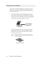
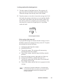
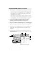
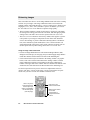
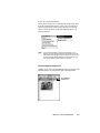
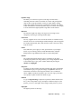
Voltage
The voltage of the scanner is indicated at the back of the scanner
near the power switch. Voltage is preset depending on your area,
ranging from 100V to 120V (U.S. and Canada), or 100V to 240V
(Europe and other parts).
In the unlikely event that you receive a scanner with a voltage
setting different from the voltage level used in your area, call your
dealer to return the scanner. Scanners marked with 100V to 120V
will not operate with 220-volt power in Europe or South America.
MODEL NO.: MRS-1200ZS
CAUTION
AC 100-120V~
47-63Hz
1A Max.
U.S. voltage requirements
2-2
Microtek User's Guide for Windows
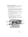
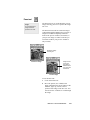
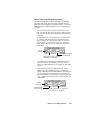
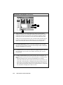
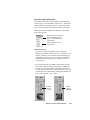
Operating the Scanner
Once the scanner is properly connected, you can perform a power-on
test. To do this, turn on the scanner, and you will see the following:
1
The POWER indicator on the front panel of the scanner lights up.
2
Next, the READY indicator beside the POWER indicator flashes
briefly. After a 30-second warm-up period, the scanner carries out
a self-test, with the scanner carriage moving back and forth about
a half-inch. If no problems are detected, the READY indicator
stays lit.
Note
3
If there are problems with the POWER and READY
indicators, see the Troubleshooting section in the Appendix.
The fluorescent lamp inside the scanner should be on too by this
time. The lamp should never go off while the scanner is on.
Note
If the scanner lamp doesn't come on, starts to flicker, or gets
dim, see the section Replacing the scanner lamp at the end of
this chapter.
Hardware Installation
2-3
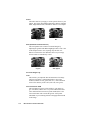
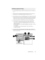
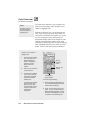
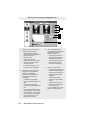
Using scanner accessories
Your scanner is a powerful imaging device, but there are scanner
accessories available that can add to your scanning efficiency.
These accessories include the Transparent Media Adapter and the
Auto Document Feeder.
•
The Transparent Media Adapter (TMA) doubles the power of
your scanner as it allows you to scan transparencies. TMAs
have their own source of lighting, which is crucial to scanning
transparencies as it prevents images from being exposed to too
much lighting and getting washed out as a result.
Transparent Media
Adapter attached to
a ScanMaker IISP
•
The Auto Document Feeder (ADF) simplifies the scanning
processing as it allows you to scan up to 50 pages of text
unattended and works with most popular Optical Character
Recognition (OCR) software.
Note
The ADF can be used to scan text and graphics in black
and white line art, halftone, or grayscale. It cannot be used
to scan color images.
Auto Document Feeder
2-4
Microtek User's Guide for Windows
Returning scanners for repair
Your Microtek scanner has been built to exacting standards. Just
like any piece of electrical equipment, however, your scanner or
the delicate parts in it are subject to wear and tear, and may
malfunction for any number of reasons. If your scanner needs to be
serviced or repaired, do the following:
In the United States (continental U.S., Alaska, Hawaii):
•
Call Microtek Technical Support to get a Repair Merchandise
Authorization (RMA) number. You can also call Microtek's
fax-back system (at 310-297-5101) to get an RMA request
form faxed to you; request Document No. 414. Fill out the
form and fax it back to Microtek; you will then be issued an
RMA number.
•
Lock the carriage (discussed in the next section) if your
scanner needs to be locked. (Not all scanners require this.)
•
Pack the scanner in the original box without any software, and
send the interface card and cables only if applicable and asked
to do so. If you have lost the original box, you will need to
buy one from Microtek for a nominal fee.
•
Send the scanner to Microtek Lab, Inc., 3715 Doolittle Drive,
Redondo Beach, CA 90278. Make sure the RMA number is on
the outside address label.
Important
Make sure the RMA number is on the address label and is
visible. Packages without an RMA number or with the wrong
RMA number on the outside of the box will be refused and
returned to sender.
Outside the United States:
•
For Canadian users: Call Microtek Technical Support. You
will be given an RMA number and address to where your
scanner can be sent for repair.
•
For users in parts other than the U.S. or Canada: Call
your authorized dealer for further instructions.
Hardware Installation
2-5
Locking the scanner carriage
You need to lock the scanner carriage if you wish to ship back
your scanner for any reason. The carriage must be locked to
prevent the mechanism from moving during shipping and getting
damaged in the process.
Important
Note
Microtek will not be liable for scanners that are damaged during
transit because the carriage had not been locked or was not
packed in the original or authorized packaging.
For scanners with parallel-port connectors (such as the
ScanMaker V300, V310, V600, etc.), there is no need to lock the
scanner.
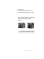
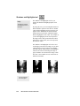
Locking models with a screw-type lock
1
Turn the scanner off and then back on. The carriage will
move forward a bit and then return to its standby position.
When the carriage stops moving, turn off the scanner. Be sure
that the carriage is in the standby position before you tighten
the locking screw. Otherwise, the carriage won’t be locked
properly and can get damaged during shipping.
2
Turn the scanner on its side and locate the locking screw at
the bottom of the scanner. To lock, turn the locking screw
clockwise one-fourth turn while pushing it in simultaneously.
The screw should stay in and not pop back out.
Locate lock at bottom of
scanner, then turn screw
clockwise to lock
2-6
Microtek User's Guide for Windows
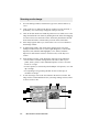
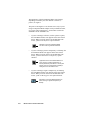
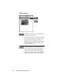
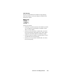
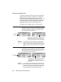
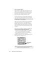
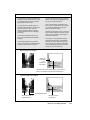
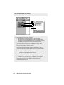
Locking models with a latch-type lock
1
Turn the scanner off and then back on. The carriage will
move forward a bit and then return to its standby position.
When the carriage stops moving, turn off the scanner.
2
Turn the scanner on its side to locate the carriage lock. Pull
the latch (the carriage lock) down (or out) until the handle
on the side of the latch locks onto the chassis. Make sure
the latch is pulled out completely (not just halfway). You
don't need to re-insert the original piece of styrofoam
under the latch.
READY POWER
Pull carriage lock down
If the carriage lock comes off:
If you pull the carriage lock down when the carriage is not in
the home position, the carriage lock may come off. To replace
the carriage lock, do the following:
1
2
3
4
5
6
7
8
Unplug the cables from the scanner.
Put the SCSI ID on 7.
Turn on the scanner. The carriage will start moving
towards the back of the scanner.
Turn off the scanner when the lamp is halfway towards
the back.
Insert the lock into position, and push it in all the way.
Change the SCSI ID to a number between 0 to 6.
Turn on the scanner and wait for about 30 seconds until
the carriage stops moving.
Turn off the scanner and pull the lock to properly lock the
carriage.
Note
In the event of a scanner malfunction, or if Item #4 does
not work because there is no power, you can also rest the
scanner on its back and wait for the carriage to start
moving to the back.
Hardware Installation
2-7
Replacing the scanner lamp
If the lamp inside your scanner does not come on or if it begins to
flicker or dim after some time, the lamp may need to be replaced.
If this is the case, call the Microtek AutoTech fax-back system at 310297-5101, then listen to the recorded instructions to request a document on how to replace the scanner lamp.
2-8
Microtek User's Guide for Windows
3
Software Installation
The software installation procedure is continually
updated to reflect the most current software
bundles of your scanner.
For the latest information on software installation,
please refer to a document entitled Microtek
Scanner Installation Guide, which is printed
separately and is included with your scanner
package.
4
Sample Scanning
ScanWizard is easy to use. The following pages show you
how to use the software to scan line art, grayscale, and color,
as well as how to enlarge your view of an image and use
image-enhancement tools. The information covered in this
section includes the following:
• Overview of ScanWizard
• Scanning a single-bit image (line art or halftone)
• Scanning a grayscale image
• Scanning a color image
• Enlarging the view of an image
• Enhancing images
• Using the Advanced Image Enhancer
• Important notes on scanning
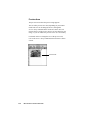
Overview
ScanWizard is the program that acts as a bridge between your scanner and your
image-editing software (such as Adobe Photoshop or Ulead PhotoImpact, etc.)
ScanWizard captures the image placed on your scanner and then delivers the
image when it is scanned to the image-editing application, where the scanned
image can then be saved or edited further.
Here are some things you can do with ScanWizard:
• Select the type of image to be scanned. For example, you can have a color
photo and scan it in the same color mode, or you can scan it in a different
mode such as grayscale or line art.
•
Perform a preview or preliminary scan, which allows you to see a
preliminary view of the image before it's actually scanned. Previewing an
image allows you to do further enhancements if necessary, and it also lets
you select the final area to be scanned in case you wish to crop the image.
When the image is ready to be scanned, clicking on the Scan button will
activate the scanning process, and the image is then delivered to your target
application.
•
While in preview mode, the image can be adjusted through the imageenhancement tools. These tools allow you to adjust image features such as
brightness, contrast, and exposure; shadows and highlights; gamma or
midtones (mid-gray levels); hue or saturation; and apply various filters for
special effects.
•
Clicking on an image-enhancement tool calls up the Advanced Image
Enhancer (AIE) dialog box. While in the AIE dialog box, you can see
thumbnail displays of the image, make changes and see the effects applied
in real time (see "before" and "after" versions instantly). These functions are
among the most powerful features of ScanWizard.
•
Create multiple scan jobs. A scan job is simply a task that you designate the
scanner to process and scan. For example, one scan job may be in grayscale
and another may be in color. The two scan jobs can then be manipulated and
scanned separately, and you can switch between scan jobs easily while
making changes. ScanWizard's ability to process various scan jobs
concurrently adds tremendous flexibility to scanning.
•
When changes are made to the image, the changes can be easily verified
through the Information window, which displays changes to RGB values.
Such information can be helpful for those working with color values.
4-2
Microtek User's Guide for Windows
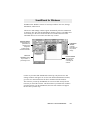
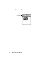
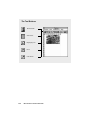
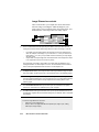
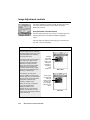
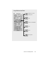
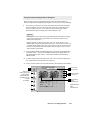
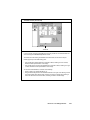
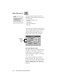
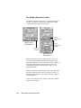
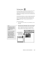
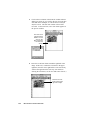
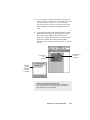
ScanWizard: The Four Windows
1
2
Information
window
Settings window
Preview window
Scan Job
window
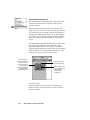
The four windows of ScanWizard:
• The Preview window has commands and tools for controlling the scanner.
• The Settings window contains scanning parameters for outputting the image and
includes the image-enhancement tools of the software.
• The Information window provides information on the preview image, such as pixel
and color information.
• The Scan Job window provides key functions in processing your scan jobs.
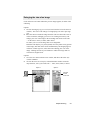
To open and close the windows:
1 Click on these arrows to open the Settings, Scan Job, and Information
windows.
2
Double-click on the close box at the top left corner of each window to close the
window. When you double-click on the close box of the Preview window, you
will exit the ScanWizard.
Sample Scanning
4-3
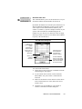
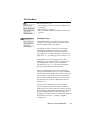
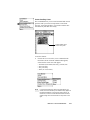
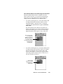
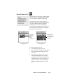
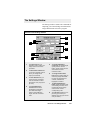
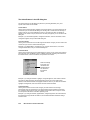
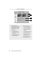
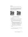
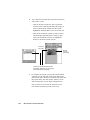
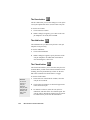
Scanning a single-bit image (line art or halftone)
1
Go to the Settings window, and from the Type menu, make your selection.
• Choose Line Art if you're scanning purely black or white images with no
shades of gray, such as pen-and-ink drawings, logos, and sketches. Line
art also applies if you're scanning an image with just one color (like a
mechanical drawing or blueprint).
• Choose Halftone to scan the image as a halftone, and select the halftone
pattern from the submenu that appears. A halftone image is like one you
see in newspapers — there is only black and white, but the eye is fooled
into seeing gray because of the way dots in the image are arranged.
2
Click on the Preview button in the Preview window. In moments, a
preliminary view of the image will appear in the preview area.
3
Click on the Scan Frame tool. With the pointer now a crossbar, move to the
image and define the scan frame (by holding down the mouse and dragging
it to draw a box). The scan frame will be enclosed by dotted lines and will
be the actual area that is scanned when you click on the Scan button.
4
At the Settings window, set the Resolution. For now, select 300 dpi. But for
optimal results, select a resolution that matches the resolution of your
output device.
5
To scan the image, click on the Scan button in the Preview window. The
image will be scanned and delivered to your image-editing software, where
it can be saved as a file.
3
2
1
4
5
3
Features grayed out in
line art mode
4-4
Microtek User's Guide for Windows
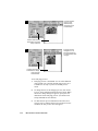
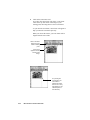
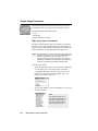
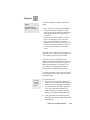
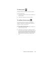
Scanning a grayscale image
1
Go to the Settings window, and from the Type menu, choose 256 shades of
gray.
2
Click on the Preview button in the Preview window. In a few moments, a
preliminary view of the image will appear in the preview area.
3
Click on the Scan Frame tool. With the pointer now a crossbar, move to the
image and define the scan frame (by holding down the mouse and dragging
it to draw a box). The scan frame will be enclosed by dotted lines and will
be the actual area that is scanned when you click on the Scan button.
4
At the Settings window, set the Resolution. Take note of the following:
• Do not select a resolution setting which is the same as that of your
printer, unless you have a dye-sublimation printer. For now, set resolution at 72 or 75 dpi.
• For laser printers, as well as inkjet and bubblejet color printers, 75 to 100
dpi is enough.
• For outputting to an typesetting machine at 1200 or 2400 dpi, set
resolution at 300 dpi.
5
To scan the image, click on the Scan button in the Preview window. The
image will be scanned and delivered to your image-editing software, where
it can be saved as a file.
3
2
1
4
5
3
Tints tool and Color
Correction feature grayed
out in grayscale mode
Sample Scanning
4-5
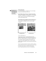
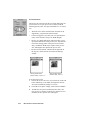
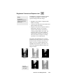
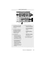
Scanning a color image
1
Go to the Settings window, and from the Type menu, choose Millions of
colors.
2
Click on the Preview button in the Preview window. In a few moments, a
preliminary view of the image will appear in the preview area.
3
Click on the Scan Frame tool. With the pointer now a crossbar, move to the
image and define the scan frame (by holding down the mouse and dragging
it to draw a box). The scan frame will be enclosed by dotted lines and will
be the actual area that is scanned when you click on the Scan button.
4
If the image appears dark to you, click on the Color Correction button in
the Settings window.
5
To adjust image quality, click on the Image Enhancement tools in the
Settings window. These tools are (left to right) Brightness, Contrast and
Exposure; Tints; Shadows and Highlights; Curve; Filters; and More
Options. For more details on how to use these tools, see the Reference
section.
6
At the Settings window, set the Resolution. Take note of the following:
• Do not select a resolution setting which is the same as that of your
printer, unless you have a dye-sublimation printer. For now, set resolution at 72 or 75 dpi.
• For laser printers, as well as inkjet and bubblejet color printers, 75 to 100
dpi is enough.
• For outputting to an typesetting machine at 1200 or 2400 dpi, set
resolution at 300 dpi.
7
To scan the image, click on the Scan button in the Preview window. The
image will be scanned and delivered to your image-editing software, where
it can be saved as a file.
3
2
1
6
7
3
4
5
4-6
Microtek User's Guide for Windows
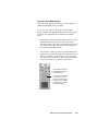
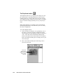
Enlarging the view of an image
Click on the Preview button. When the preview image appears, do either of the
following:
Option 1
1 Click on the Magnifying Lens tool (3rd tool from the left in the Preview
window). The cursor will change to a magnifying lens with a plus sign
in it.
2 Move the cursor to inside the image and click. The area where the cursor is
will be zoomed in, enlarging your view of it. Clicking successively will
enlarge your view of the image in the ascending order on the zoom scale
— from 100% to 200%, to 400%, and to 800%.
To reduce your view of the image after it was magnified:
Hold down the Shift key on your keyboard, move the pointer to any portion
of the image, and click on the mouse simultaneously. The magnifying lens
will show a minus sign in it, at the same time reducing your view of the
image. Clicking successively will continue to reduce the image until it is
restored to its original scale.
Option 2
1 Go to the View menu in the Preview window, and choose the Show Info
window command.
2 Click on the Zoom Level Display in the Information window. From the
drop-down list, select your zoom scale — 100%, 200%, 400%, or 800%.
Option 1
Lens tool
Option 2
Click and
choose
zoom level
Sample Scanning
4-7
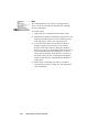
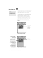
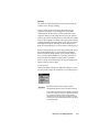
Enhancing images
This section discusses how to use the Image Enhancement tools in the scanning
software for your images. The image enhancement tools are located in the
Settings window and include Brightness, Contrast and Exposure; Shadows and
Highlights; Curve; Tints; Filters; and More Options. In addition, you can use
the Auto and Color Correction buttons to optimize image quality.
• The Auto button optimizes contrast for the image. It operates by calculating
the settings of the image part within the scan frame, and then applying those
settings to the scan frame. Do not use this option with Color Correction.
• The Color Correction button is turned on by default, and it applies a generic
color profile to your image to compensate for the minor color shifts that
occur in all scanning. If you have Microtek's DCR (Dynamic Color Rendition) color calibration system installed, the Color Correction feature will
apply DCR instead of the generic color profile. (DCR is an option.) Do not
use this option with any other setting, such as the Curve tool or Auto.
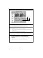
Using an image enhancement tool
• Click on an image enhancement tool. The Advanced Image Enhancer (AIE)
dialog box will come up (see next page), and you can then apply image enhancements there and also switch to other tools while in the AIE dialog box.
• Click on the Window Expansion button in the Setting window (see graphic
below). This will reveal the bottom half of the Settings window, with the
image enhancement controls corresponding to the image enhancement
buttons in the upper half of the window. The Reset button at the bottom of the
window has the same function as the Reset button in the AIE dialog box.
Use the first option for more precise control over adjustments and to see
"before" and "after" versions of the image. Use the second option for quick
results once you have become more familiar with these tools.
Click on any of the
image-enhancement
tools to adjust your
image. The AIE dialog
box will then appear
(see next page).
4-8
Microtek User's Guide for Windows
Click here to see
bottom half of window
Bottom half of window
has controls
corresponding to
image-enhancement
buttons.
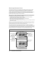
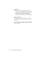
Using the Advanced Image Enhancer
When you click on any of the Image Enhancement buttons in the Settings
window, the Advanced Image Enhancer (AIE) dialog box appears. In this
dialog box, you can do the following:
1
Select the scan job and image to which image enhancement controls will be applied.
A scan job is a task that you designate the scanner to scan and process, and the
scan job in the AIE dialog box corresponds to the scan job in the Scan Job window.
If you have multiple scan jobs open, you can switch among these jobs and see the
image to be processed.
2
See a thumbnail of the image captured by your scanner, and see how the image
changes when adjustments are applied to it. The "before" and "after" images are the
left and right thumbnails (2a and 2b) in the dialog box.
3
Select another image enhancement tool by clicking on any of the buttons displayed
in the vertical toolbar on the right side of the dialog box.
4
Click on an action button to achieve a particular effect. These buttons are on the
upper right side of the dialog box.
• Click OK to accept changes you have made and to close the AIE dialog box.
• Click Cancel to abandon all changes and to close the AIE dialog box.
• Click Reset to restore settings to default. When you do this, the Reset dialog box
appears, allowing you to reset your settings.
• Click Revert to cancel out the effects of the currently used tool. If you have used
three tools, for instance, Revert will preserve the changes of the first two tools
and ignore the changes made by the third.
Click here to use
another imageenhancement tool
3
1
Choose your scan
job here
4
Click on a button for
an action
2b
The image 2a
before
enhancements
are applied
Sample Scanning
See changes to the
image with your
enhancements
4-9
Important scanning notes
Here are some tips to help you with scanning. If you're not familiar with the
scanning process, review the preceding pages on the individual scanning tasks to
get a feel for the software and how it works. Also, if some of the concepts
discussed in these pages are not familiar to you, see the Reference section of the
manual for a detailed discussion.
For previews and scans
• Select the image type correctly when you do a preview or scan. For instance,
if you're only previewing or scanning grayscale images, do not select a color
mode, as this slows down the process and creates bigger files than is
necessary. If you're only previewing grayscale images, you can turn off the
Live Preview option in the Preview Setup command.
• Scan Frame tool: At its simplest, the tool is used to crop preview images for
final scanning. However, you can also use the Scan Frame tool to create
multiple scan frames, and with the creation of multiple scan frames, this
means you're actually creating duplicate scan jobs (based on the current scan
job). Each scan frame (and by extension, each scan job) can have its particular
settings, so that one scan job can be in grayscale; another in color with a
certain brightness setting; and yet another in color with a filter.
• Zoom Preview tool: Use this tool to enlarge a part of the preview image and
then previewing it in high resolution. The enlarged view obtained from the
zoom preview tool is NOT the same as the view obtained from the
Magnifying Lens tool, which is simply an enlarged view (but not in high
resolution).
• Input-Output dimensions and Aspect Lock: Use the input dimensions to
specify your scan frame; or if you wish, you can simply drag on the scan
frame to whatever size you want, and the dimensions will be reflected
automatically in the boxes for input width and height. The input dimensions
can be changed only if your Aspect Lock is OFF.
The output dimensions, on the other hand, determine the width and height of
your image when output to a monitor or printer. The output dimensions can be
changed only if the Aspect Lock is ON. The output dimensions are calculated
dynamically, and the system looks at other variables such as your resolution
and scaling to determine the final output dimensions. This means that you
may specify output dimensions of 5" x 7", but because of intervening
variables, the actual output dimensions may be 4.85" x 6.9" — which is the
closest the system can produce given your other variables.
• Before scanning an image, select the correct resolution setting. Remember
that overly high settings slow down your scanning and create huge
unmanageable files. For more details, see the discussion on resolution in the
Basic Concepts and the Reference section.
4-10
Microtek User's Guide for Windows
For image enhancement
• By default, the Color Correction button is turned on, which means your
image is color corrected as a matter of course to compensate for the minor
color shifts that normally occur in all scanning. If you have Microtek's DCR
installed, the DCR color profile is applied instead of the generic color
profile.
• One useful image-enhancement control is the Auto button, which optimizes
contrast for the entire image. Auto works by calculating the settings of the
image part inside the current scan frame, and then applies those settings to
the scan frame. If your scan frame encloses a dark portion and then you
apply Auto, this will have the effect of lightening the dark portion (the part
of the image within the scan frame). Conversely, if your scan frame
encloses a light portion and then you apply Auto, this will make that light
part darker. In both cases, the pixels are remapped to a broader range, so
that the image parts in the scan frame are darkened or lightened
accordingly.
• Use the powerful image enhancement tools to improve your image if
necessary, and familiarize yourself with the features of the Advanced Image
Enhancer (AIE) dialog box. This is one of the strengths of the software.
While in the AIE dialog box, you can see thumbnails of the image, make
image enhancements there, and see effects of the changes ("before" and
"after" versions ) in real time. You can also switch from one tool to another,
as well as switch among various scan jobs if you have multiple scan jobs.
Familiarize yourself too with the various action buttons in the AIE dialog
box and how they work. This is important.
For scan jobs
• Use the flexibility provided by the scan job functions to process your various
scans. With the Scan Job window, you can (among other things) create new
scan jobs, copy settings for a duplicate scan job, and save scan jobs as
templates.
• To master the intricacies of the scan job functions, familiarize yourself with
the usage of the Scan Frame tool and the Smoked Glass Background feature,
both of which are linked to the functions of the scan job. This is discussed in
the Reference section.
Sample Scanning
4-11
Auto and Color Correction
Original
Color Correction applied:
Scanned image matches original
Auto control applied:
Contrast optimized for image
A
Brightness and Contrast
Original
Brightness increased
Brightness decreased
Contrast increased
Contrast decreased
B
Exposure and Saturation
Original
Green exposure increased
Red exposure increased
Blue exposure increased
Saturation increased
Saturation decreased
C
Shadows and Highlights
Original image and original input values
Shadows emphasized and correspoding changes to input values
Highlights emphasized and corresponding changes to input values
D
Curve
Original image with straight diagonal curve
Image with curve moved up
Image with curve moved down
Image posterized with corresponding curve
E
Tints
Original
F
Filters
Original
Blur
Blur More
Sharpen
Sharpen More
Edge Enhancement
Emboss
G
Descreen
Before Descreen: Image scanned from a
printed page, resulting in moirés
After Descreen: Same image scanned with
descreen turned on (magazine option, 133 lpi)
H
5
Reference
This section is a listing of features found in the *ScanWizard
for Windows scanning software. The reference information is
organized in four parts, following the structure of the software which shows the four major windows of the program
(Preview, Settings, Information, and Scan Job).
Twain compliance
ScanWizard for Windows is a Twain-compliant program. This
means that it conforms to the Twain software industry
standard for controlling imaging devices such as scanners,
film recorders, and video capture cards.
The Twain standard allows software applications and hardware imaging devices to communicate directly. In practical
terms, this means that while using applications that support
Twain (such as Adobe Photoshop), you can access the scanner
through ScanWizard for Windows. When a scan is performed,
the captured image is then automatically placed inside the
original application.
With a Twain-compliant application, you do not have to leave
the application you are working in, and the captured image
does not have to be saved as a separate file before being used
by the application. This allows you to scan images right into
your favorite image-editing application, word processor,
spreadsheet, or any Twain-compliant application that makes
use of images.
*All references made in the manual to the scanning
software are to the ScanWizard for Windows. In other
packaging components, the scanning software may also
be called the ScanWizard scanner controller.
Overview
ScanWizard is the program that acts as a bridge between your scanner and a
target application, such as Adobe Photoshop orUlead PhotoImpact. In practical
terms, this means you use ScanWizard to scan or capture images placed on
your scanner and place them in a target application. Once the images are
delivered to the target application, they can be saved or edited further.
Some of the things you can do with ScanWizard for Windows
• Select the type of image to be processed
and scanned. You can put one type of
image on the scanner and scan that in its
original form, or you can scan it in
another form altogether. For example,
you can have a color photo and scan it in
the same color mode, or you can scan it
in a different image type such as
grayscale or line art.
• While in preview mode, the image can
be adjusted through the imageenhancement tools in the Settings
window. These tools allow you to adjust
image features such as brightness,
contrast, and exposure; shadows and
highlights; gamma or midtones (midgray levels); hue or saturation; and
apply various filters for special effects.
• Clicking on an image-enhancement
tool calls up the Advanced Image
Enhancer (AIE) dialog box. While in the
AIE dialog box, you can see thumbnail
displays of the image, make changes
and see the effects applied in real time
(see "before" and "after" versions
instantly). You can also switch to
another tool without leaving the AIE
dialog box, as well as switch among
scan jobs if you have multiple scan
jobs. The image-enhancement
functions are among the most powerful
features of the ScanWizard.
5-2
• Perform a preview or preliminary scan.
This is done with the Preview button in
the Preview window, and it allows you
to see a preliminary view of the image
before it's actually scanned.
Previewing an image allows you to do
further enhancements if necessary,
and it also lets you select the final area
to be scanned in case you wish to crop
the image. When the image is ready to
be scanned, clicking on the Scan
button will activate the scanning
process, and the image will then be
delivered to your target application.
• When changes are made to the image,
the changes can be easily verified
through the Information window, which
displays changes to RGB values. This
information can be helpful for those
working with color values.
• Create multiple scan jobs. A scan job
is simply a task that you designate
the scanner to process and scan. For
example, one scan job may be in
grayscale and another may be in
color. The two scan jobs can then be
manipulated and scanned separately,
and you can switch between scan
jobs easily while making changes.
The ScanWizard's ability to process
various scan jobs concurrently adds
tremendous flexibility to scanning.
Microtek User's Guide for Windows
ScanWizard for Windows
ScanWizard for Windows consists of four major windows: Preview, Settings,
Information, and Scan Job.
The Preview and Settings windows appear automatically after the ScanWizard
is started up. The Scan Job and Information windows, however, are hidden, and
to see them, go to the View menu in the Preview window and click on the
commands Show Scan Job window and Show Info window.
Settings window
contains scanning
parameters for
outputting the
image and
includes imageenhancement tools
Scan Job
window provides
key functions in
processing scans
Information
window
provides
information on
the preview
image
Preview window
has commands
and tools for
controlling the
scanner
On the very first time that ScanWizard is started up, only the Preview and
Settings windows will appear. To see the Scan Job and Information windows,
go to the View menu and choose the Show command for both windows.
The next time you start up ScanWizard, the screen will look exactly like the
last time you exited the software. This means that if you had all four windows
open the last time you quit ScanWizard, the same four windows will appear
the next time you start it up.
Reference: The Preview Window
5-3
The Preview Window
The Preview window is the most prominent
window of the four major windows, and it
includes the various commands and tools for
controlling the scanner.
Elements of the Preview window
1
3
2
4
6
1
2
3
5-4
The Menu Bar includes the
different menus for setting up the
scanner (Scanner menu),
controlling view options (View
menu), customizing the software
(Preferences menu), and
accessing online help (Help
menu).
The Tool buttons simplify the
performance of certain tasks.
The Tool buttons are (left to right)
Zoom Preview, Scan Frame,
Magnifying Lens, Hand, and
Color Picker.
The Action buttons generate a
specific action from the scanning
software. The Action buttons
include Preview and Scan.
Microtek User's Guide for Windows
5
4
The Scan Material Status
icon shows your scan
material, whether it's
reflective, positive, or
negative.
5
The Preview Area is where
the preview image appears
after you click on the
Preview button.
6
Rulers are located on both
sides of the window to help
you with measurement and
alignment. The ruler unit
can be selected by clicking
on the arrow at the 0,0
point of the rulers.
The Menu Bar
Reference: The Preview Window
5-5
The Scanner Menu
The Scanner Menu lets you:
• Show your scanner model or select a scanner if you
have multiple scanners
• Get information about your scanner
• Get information about the SCSI chain
Scanner Model
The top of the scanner menu displays the scanner model
you're using and its SCSI ID. If you have multiple
scanners on your system, all the scanners are shown with
their respective SCSI IDs, and the current scanner is
indicated by a check.
Only one scanner can be accessed at a time. To switch
among various scanners, select the scanner to be used.
The scanner is displayed
here with its SCSI ID. The
The current scanner is
marked by a check.
Get Current Scanner Info
This command provides information about your current
scanner. When you choose this command, a dialog box
appears showing the scanner model, SCSI ID number,
and firmware version.
5-6
Microtek User's Guide for Windows
Get SCSI Chain Info
This command allows you to see the SCSI devices on your
SCSI chain and the SCSI ID number of the devices.
By default, all numbers are selected by the check boxes. To
allow ScanWizard for Windows to start up more quickly,
select only the boxes that match the SCSI ID of your
scanner (or scanners, if you have multiple scanners on your
system). This will make the ScanWizard bypass the
numbers for your other devices and focus effort on simply
detecting scanners. If you're not sure about which numbers
to specify, check all the boxes.
The SCSI Chain dialog box
Click on the
Probe button to
update
information or
mount a SCSI
device if it's not
showing in the
dialog box.
SCSI devices are
shown with their
corresponding
SCSI ID numbers.
Select your
interface
card here.
To let ScanWizard
start up more quickly,
check only the boxes
that match the SCSI
ID of your scanner.
To use the SCSI Chain feature:
1 Choose the Get SCSI Chain Info command. The SCSI
Chain dialog box will appear.
2
If your scanner does not show, click on the Probe
button. Make sure your scanner is connected and
turned on.
3
Make sure too that the correct interface card is shown
in the card selection box. If not, choose the correct
interface card.
4
Check the box corresponding to your scanner or
scanners. Click OK to close the dialog box.
Reference: The Preview Window
5-7
Exiting ScanWizard
To exit ScanWizard for Windows, double click on the close
box on the upper left side of the Preview window.
Double-click here to
exit ScanWizard
5-8
Microtek User's Guide for Windows
The View Menu
The View menu lets you:
• Get a full page preview or zoomed-in (enlarged) view
of an image
• Resize the preview window
• Show or hide the Settings, Information, and Scan Job
windows
Full Page Preview
This command shows one of the two viewing modes
available for your image (the other being the zoomed
preview, explained in the next section).
The full page preview is a preview of your image as
defined by the parameters set in the Preview Setup
command (in the Preferences menu). For instance, if
your image is 8" x 5" but the dimensions in the Preview
Setup are 4" x 3", your full page preview will be 4" x 3".
The maximum size of the full page preview varies,
depending on your scanner model. For example, if the
scan bed (the glass surface) of your scanner has a
maximum size of 8.5" x 11", the maximum full page
preview will be limited to those dimensions.
The size of the full page preview can be changed by
setting new dimensions in the Preview Setup command.
The new dimensions will take effect, however, only with
the next preview. This means you need to click on the
Preview button so that the scanner does a new preview;
only then will you see the new dimensions of the full
page preview.
You may wish to change the size of your full page
preview to improve performance and save memory. A
smaller preview area will occupy less memory, speed up
processing, and yield a higher-resolution preview. This is
because ScanWizard takes your preview image and
dynamically calculates how best to display that image in
the smaller preview area — resulting in a higherresolution view.
Reference: The Preview Window
5-9
Full page preview
(8.5" x 11") as
determined by
dimensions in the
Preview Setup
1
Preview area matches
dimensions in Preview
Setup command
Full page preview
changes to 6" x 9"
because dimensions
in Preview Setup were
changed
2
Preview area changes
as dimensions change.
Note new ruler
measurements.
To use full page preview:
1 Full page preview is the default view. It will be dimmed
if the current view is already the full page preview. It is
available for use only if you are in zoomed preview
mode.
5-10
2
To change the size of the full page preview, click on the
Preview Setup command in the Preferences menu. When
the Preview Setup dialog box appears, specify the new
dimensions for the full page preview. (See the Preview
Setup command for more details.)
3
To make the new preview dimensions take effect, do a
new preview by clicking on the Preview button. In a few
moments, the new preview area will appear.
Microtek User's Guide for Windows
Zoomed Preview
This command displays a magnified view of your image
when you use the Zoom Preview tool.
The zoomed preview is the view of a specific part of the
image shown in higher resolution with more visible detail.
If you have zoomed preview enabled, the view is stored in
memory, and you can easily switch between full page
preview and zoomed preview.
The zoomed preview is different from the zoomed-in view
obtained from the Magnifying Lens tool. The zoomed-in
view is simply an enlarged view, but it is not in high
resolution.
Full page preview
Zoomed preview
To use zoomed preview:
Click on the zoom preview tool (leftmost tool in the
Toolbar that looks like a microscope). Move the pointer to
the preview image and draw a scan frame around the area
to be zoomed in, then click inside the scan frame. The
selected area will be magnified to give you the zoomed
preview. For more details, refer to the section on the Zoom
Preview tool.
After you use the zoom preview tool to create the zoomed
preview, the Zoomed Preview option in the View menu will
be enabled. You can then switch between Full Page
Preview and Zoomed Preview as your viewing modes.
Reference: The Preview Window
5-11
Resize Window to Fit
This command adjusts the preview window to fit the
preview area.
In the example below, the preview window is larger than
the preview area, as denoted by the empty space below the
vertical ruler. In other instances, the preview window may
also exceed the preview area if you manually enlarged the
preview window (by dragging on the resize box).
To utilize window space more efficiently, use this command to resize the preview window.
Before resize
After resize
To use this feature:
Choose the command Resize window to fit in the View
menu.
This command is available only if the current zoom level is
100%, and is disabled if zoom is set to other levels. To
verify the zoom level, open the Information window and
look up the zoom level.
5-12
Microtek User's Guide for Windows
Show / Hide commands
These commands allow you to switch between showing or
hiding the Settings, Scan Job, and Information windows on
your screen. The commands also have their tool-button
counterparts in the form of three arrowheads on the right
edge of the toolbar.
To use this feature, do either of the following:
•
Choose the correct command from the View menu for
viewing a window. When the window appears, you
can hide it by choosing the particular Hide command
for it.
•
Note
Another way
to close or
hide an active
window is to
double-click
the close box
on the left
corner of the
active
window. Do
not doubleclick the close
box of the
Preview
window,
however,
because this
will cause you
to exit the
program.
Click on the Show/Hide tool buttons in the Preview
window.
1
2
3
1
Click on the first arrow to show or hide the
Settings window.
2
Click on the second arrow to show or hide the
Preview window.
3
Click on the third arrow to show or hide the Info
window.
Reference: The Preview Window
5-13
The Preferences Menu
The Preferences menu lets you:
• Choose the correct scan material
• Create effects like invert and mirror
• Create cursor lines to help you with alignment
• Control the size of your preview window
• Keep the preview image even after exiting
ScanWizard
• Create a smoked glass background to help distinguish the current scan frame
• Set other options, such as specify a working directory
for files
Scan Material
This command allows you to select the correct scan
material. Scan materials can be classified into three
types:
• Reflectives, such as photographs or prints.
• Positives, such as slides.
• Negatives, such as the negative film you use for your
camera.
The default scan material depends upon the scanner
you're using, and the choices available to you in the
Scan Material submenu will also depend on your
equipment.
For instance, the positive option appears only if you're
using a Transparent Media Adapter (TMA) with your
scanner. The negative option appears only if you have
DCR installed and are using the TMA to scan a
negative.
If you are scanning negatives or positives, make sure
you specify the correct scan material, or you will get
inaccurate scanning results.
Note
The Scan Material function is also related to the Tints tool,
an image-enhancement function in the Settings window.
Refer to that section for more details.
5-14
Microtek User's Guide for Windows
To use the scan material feature:
Choose the Scan Material command in the Preferences menu.
From the submenu that appears, select your scan material; a
check will appear next to the selected option. The selected
option will also be shown in the Scan Material Status icon
(discussed below).
Note
If your Preview window is close to the right edge of your
monitor, the Scan Material submenu may appear on the left
side instead of on the right (as shown above). To resolve this,
move the Preview window towards the left to create enough
room for the submenu to drop down on the right.
The Scan Material Status icon
Another way to access the Scan Material menu is to use the Scan
Material Status icon, located to the right of the Scan button.
Scan Material
Status icon
Reference: The Preview Window
5-15
The appearance of the Scan Material Status icon changes,
depending on whether your scan material is reflective,
positive, or negative.
The positive and negative icons become active only if you're
using a Transparent Media Adapter with your flatbed scanner,
or if you're using a transparency / slide scanner such as the
ScanMaker 45t or ScanMaker 35t.
•
If you're scanning a reflective (such as a photo or print),
the Scan Material status icon appears in the form shown
below. When you click on the icon and hold down the
mouse, you'll see the Reflective option checked.
Appearance of the Scan Material Status
icon when scanning reflective materials.
•
If you're scanning a positive transparency or filmstrip, the
Scan Material Status icon appears in the form shown
below. When you click on the icon and hold down the
mouse, you'll see the Positive Transparency option
checked.
Appearance of the Scan Material Status icon
when scanning a positive transparency or
filmstrip. Notice the perforations on the top and
bottom of the icon (characteristic of slides) to
distinguish it from the reflective icon.
•
If you're scanning a negative transparency or filmstrip,
the Scan Material status icon appears in the form shown
below. When you click on the icon and hold down the
mouse, you'll see the Negative Film option checked.
Appearance of the Scan Material Status icon
when scanning a negative transparency or
filmstrip.
5-16
Microtek User's Guide for Windows
Invert
This command creates a negative of an image. The Invert
effect is applied to the whole preview image; it cannot be
used for only a specific portion of the image.
When an image is inverted, the brightness value of each pixel
is converted to the inverse value on the 256-step color values
scale. For example, a pixel in a positive image with a value of
255 is changed to 0, and a pixel with a value of 5 is changed
to 250.
Original
Invert
To use this feature:
Choose the Invert command in the Preferences menu. A
check appears next to the command when it is enabled.
Reference: The Preview Window
5-17
Horizontal Mirror
This command allows you to flip the image so that a mirror
effect is created. The Mirror effect is applied to the whole
preview image; it cannot be used for only a specific portion
of the image.
Original
Horizontal Mirror
To use this feature:
Choose the Horizontal Mirror command in the Preferences
menu. A check appears next to the command when it is
enabled.
When the mirror image appears, the scan frame will still be
in the old location, and you will need to move the scan
5-18
Microtek User's Guide for Windows
Cursor Auxiliary Lines
This command allows you to create horizontal and vertical
grid lines with your cursor to help define a scan frame
precisely. Using the grid lines, you can also read the measurements off your ruler more easily.
Cursor auxiliary lines
on the x and y axis
To use this feature:
1 Choose the Cursor Auxiliary Lines command in the
Preferences menu. From the submenu that appears,
select how the cursor lines will appear.
• On both x (horizontal) axis and y (vertical) axis
• On x axis only
• On y axis only
• None (no cursor lines)
Note
If your Preview window is close to the right edge of your
monitor, the Cursor Auxiliary Lines submenu may appear on
the left side instead of on the right (as shown above). To
resolve this, move the Preview window towards the left to
create enough room for the submenu to drop down on the
right.
Reference: The Preview Window
5-19
2
Click on the Scan Frame tool.
To see how the cursor lines work, draw a scan frame.
Click on the top left corner of the image as your
starting point, then drag down to form a scan frame.
As you draw the scan frame, cursor lines will appear to
help you draw the scan frame precisely.
When you release the mouse, your scan frame will be
aligned with the cursor lines.
Click on the Scan
Frame tool, then
define a starting
point.
Cursor lines
appear to the top
and left of the
image.
As you drag the
mouse down, the
scan frame is
aligned with cursor
lines on the x and y
axis (based on your
selected option in
the submenu).
5-20
Microtek User's Guide for Windows
Preview Setup
This command allows you to set the dimensions of your
preview area. When the Preview Setup dialog box (below)
comes up, click on the option you need or specify your
parameters.
Options
described
below
Option
Description of function
Live Preview
This option applies only to color scanners. • If Live Preview is enabled,
the next option, Color Preview, will be dimmed.
If Live Preview is on:
• Changes you make to the preview image are shown instantly (for
example, switching from color to grayscale).
• If you're scanning in grayscale and live preview is on, the image
appears in color unless you specifically change image type in the Type
box (in the Settings window) to a grayscale mode. This happens
because Live Preview always does previews in color.
If Live Preview is off:
Your preview will be in accordance with your image type (i.e., if you have a
grayscale image, your preview is in grayscale; with a color image, you get
a color preview). If you apply any image-enhancement control, the
changes will not be apparent until you do a new preview (click on the
Preview button again). Turn off Live Preview if you're previewing or
scanning in grayscale to speed up the process.
Color Preview
This option applies only to three-pass color scanners, and is enabled only
if Live Preview is not selected. If this option is turned on, the image will be
scanned in whatever scan mode is specified in the Type box (in the
Settings window). If it is turned off, the image will be scanned in grayscale.
Fast Preview
This option allows you to choose your preview mode.
• If Fast Preview is on: The preview is process is faster, but the quality of
the preview image is a little coarse.
• If Fast Preview is off: The preview process is slower, but the quality of
the preview image is improved.
The Fast Preview option is a hardware-related feature and may or may not
be available depending on your scanner model.
Reference: The Preview Window
5-21
The Preview Area
The Preview Area option in the Preview Setup dialog box lets
you select the size of your preview area. Choose from the
following options: letter, A4, legal, maximum size, or custom
size.
•
Maximum refers to the maximum scan area that can be
supported by your particular scanner model.
•
Custom will appear if you enter your own specifications
in any of the edit boxes (Top, Left, Width, Height).
•
The Top, Left, Width and Height edit boxes allow you to
specify the dimensions of the preview area. Top and Left
refer to the starting points of the preview area on the x
and y coordinates. Width is the expanse of the preview
area, and Height is the depth of the preview area.
•
The unit of measurement, indicated on the right side of
the Top box, reflects the unit selected in the Settings
window.
Size of preview area if
preview setup is 8. 5" x 11"
Size of preview area if
preview setup is 6" x 9"
To set the preview area:
1 Choose the Preview Area size. If you enter any of the edit
boxes marked Top, Left, Width, or Height, the Preview
Area size automatically changes to Custom.
5-22
2
Click OK to accept the settings; click Cancel to abandon.
3
To make the new preview dimensions take effect, do a
new preview by clicking on the Preview button. In a few
moments, the new preview area will appear.
Microtek User's Guide for Windows
Keep Preview Image
This command allows you to retain the last preview image
you used; the preview image is kept in the preview window
after you exit ScanWizard.
The next time you start up ScanWizard, this last preview
image is again displayed in the preview window.
To use this feature:
Choose the Keep Preview Image command in the Preferences
menu. A check appears next to the command when it is
enabled.
Reference: The Preview Window
5-23
Smoked Glass Background
This command helps you distinguish the current scan frame
from the rest of the material for greater visibility of the
current scan frame.
With the Smoked Glass feature turned on, the part of the
image within the current scan frame will stand out, while the
rest of the image (the "irrelevant" material) is relegated to a
background resembling smoked glass. If you have multiple
scan frames, only the current scan frame stands out, and the
inactive scan frames are hidden behind the smoked glass
screen.
The Smoked Glass Background, then, helps you focus on the
part of the image within the current scan frame, and is
particularly helpful when you are editing a scan frame or
applying image-enhancement controls. This way, the changes
can be seen more clearly and stand out from the rest of the
material. (See the next section for more details. )
Part of image is in
another scan frame,
but this is not the
current scan frame,
as the image is
dimmed and hidden
behind smoked
glass background.
Current scan frame
(with pulsing lines)
Part of image not in
any scan frame and
also hidden by
smoked glass
background
To use this feature:
Choose the Smoked Glass Background command in the
Preferences menu. A check appears next to the command
when it is enabled.
5-24
Microtek User's Guide for Windows
How Smoked Glass works with image enhancement
When the Smoked Glass feature is enabled, it becomes
linked with the functions of a scan frame and signficantly
impacts the way image-enhancement controls and other
settings (such as resolution) are seen. Details follow.
•
If you have smoked glass on, a scan frame defined, and
set image-enhancement and other controls (such as
changing brightness, applying a filter, or changing
resolution), the enhancements are applied to the scan
frame alone.
This means that the part within the scan frame may
change in appearance (as it now has different settings),
but because smoked glass is on, the rest of the image
hidden behind the smoked glass remains unaffected.
With Smoked Glass
on, controls are
applied to the part of
the image within the
scan frame. Notice
how right half of image
remains behind
smoked glass.
•
If you have smoked glass off, a scan frame defined, and
set image-enhancement and other controls, the enhancements are still applied to the scan frame alone. But
because smoked glass is turned off, it appears that the
whole image has been altered. This is not the case, as
only the scan frame is affected.
With Smoked
Glass off, controls
are applied to the
entire image.
Reference: The Preview Window
5-25
More
This command allows you to specify a working directory
where you can save all temporary and data files, including
files for job templates.
To use this feature:
1 Choose the More command in the Preferences menu.
5-26
2
When the More Preferences dialog box appears, press and
hold down the Working Directory box. From the pop-up
menu that appears, choose your working directory.
3
If you click on the folder icon, the Directory Browser
dialog box appears for you to choose your working
directory. Click OK to close this dialog box. Whatever
directory you specify is automatically added to the pop-up
menu (in the More Preferences dialog box) for you to
choose from in the future. If the directory you specify is
not found or does not exist, a warning message appears,
and the current directory of ScanWizard for Windows is
used instead.
4
When you have completed your choices, click OK to
close the More Preferences dialog box. The changes take
effect immediately.
Microtek User's Guide for Windows
The Help Menu
The Help menu lets you access online help for
ScanWizard for Windows.
The Help menu uses standard Windows conventions for
obtaining online help. If you are not familiar with this
procedure, refer to your Microsoft Windows user's
guide.
About
This command gives you information on the
ScanWizard for Windows scanning software.
ScanWizard for Windows is also referred to in the
About screen as the ScanWizard scanner controller.
Reference: The Preview Window
5-27
The Tool Buttons
Zoom Preview
Scan Frame
Magnifying Lens
Pane
Color Picker
5-28
Microtek User's Guide for Windows
Zoom Preview tool
Usage
To magnify the view of
a preview image in high
resolution, and to let
you switch between full
page preview and
zoomed preview.
The Zoom Preview tool gives you the zoomed
preview, which is an enlarged, high-resolution
view of an image with more visible detail.
The zoomed preview is different from the
zoomed-in view, which is not a high-resolution
view and is obtained instead by using the
magnifying lens tool. By using the zoom
preview tool and creating the zoomed preview,
you can then switch easily between full page
preview and zoomed preview.
Area to be
zoomed in
with the
Zoom
Preview tool
Selected image
part zoomed in
(enlarged) in high
resolution
Zoomed preview
Full page preview
To use the Zoom Preview tool:
1 Click on the Zoom Preview tool.
2
Move the pointer to the preview image and
draw a scan frame around the area to be
zoomed in.
3
Click inside the scan frame. The selected
area will be magnified to give you the
zoomed preview. Only the area inside the
defined scan frame will be zoomed in. To
zoom in on a larger area, go to full page
preview and change the size of the scan
frame.
Reference: The Preview Window
5-29
Scan Frame tool
Usage
To create a scan frame
or multiple scan frames
in the preview image.
The Scan Frame tool lets you create or modify a
scan frame, which is the active area on which
controls and commands can be applied.
The Scan Frame tool can also be used to create
multiple scan frames, but only one can be
current at a time; the current scan frame is
indicated by a marquee (marching ants). The
current scan frame can be more easily distinguished if you turn on the Smoked Glass
Background command (in the Preferences
menu).
Current scan
frame is
denoted by
marquee
Image with single scan frame
Another scan frame,
which can be
distinguished by the
marquee around the
left half of the image.
This is not the current
scan frame, however,
as the part of the
image enclosed by the
scan frame is
dimmed. Smoked
Glass Background is
on so that the current
scan frames can be
seen more easily.
5-30
Current
scan frame
Image with multiple scan frames
Microtek User's Guide for Windows
To use the Scan Frame tool:
1 Click on the Scan Frame tool.
2
Move the pointer (now a crossbar) to the preview image, and
draw a frame enclosing the area to be selected. When you
release the mouse, the scan frame will be in a marquee.
To make multiple scan frames (which would add scan jobs),
hold down the Shift key and drag the mouse. For more
information on scan jobs, refer to the Scan Job section of the
Reference.
3
To resize the scan frame, do either of the following:
• Move the cursor to any corner of the frame; the pointer will
change to a double-headed arrow. Hold down the mouse,
and drag to form a new area, then release the mouse; or
• Click on the Scan Frame tool again and restart the areaselection process.
Reference: The Preview Window
5-31
Magnifying Lens tool
Usage
To zoom in or enlarge
your view of the preview
image.
The Magnifying Lens tool enlarges your view of
the preview image, allowing you to set the scan
frame with greater precision if you need to.
Only your view of the preview image is
changed; the actual size of the image remains
unaffected.
Each click of the Lens tool magnifies or reduces
by a factor of 2. Thus, the magnification levels
increase from 100% to 200%, to 400%, and to
the maximum 800% (see Note below).
If the portion that you want to magnify includes
most of the preview area, the lens tool will
magnify the view only slightly. To solve this,
enlarge the size of the preview area (through the
Preview Setup command), or create a smaller
selection area.
Note
If the
Information
window is open,
the zoom level
will be
indicated.
This means you
can also zoom
in by selecting
the appropriate
zoom level in
the Information
window.
5-32
Original image view
Image view enlarged with
Magnifying Lens tool
To use the Magnifying Lens tool:
1 Click on the Magnifying Lens tool.
2
Place the pointer — now a lens with a plus
sign inside it — on the image and click.
To reduce the view, hold down the Shift key
and click again. The plus sign changes to a
minus sign when you hold down the Shift
key.
Microtek User's Guide for Windows
Pane tool
Usage
To scroll through an
image and move
parts of it into view.
The Pane tool lets you scroll through a preview
image, allowing you to move parts of the image
into view.
The Pane tool can used for zoomed-in images
(enlarged through the Magnifying Lens tool), or
images not included completely within the
frame of the preview window (for instance, if
your preview image is 8 inches wide and you
resized the width of your preview window to
only 5 inches).
Zoomed-in image
of three girls
Zoomed-in image
Image moved
in from the
right. Girl on
extreme left is
now out of the
view frame.
Scrolled image
To use the Pane tool:
1 Click on the Pane tool.
2
Move the pointer (now a hand) to the
image. Hold down the mouse and move the
hand left, right, up, or down, and see
portions of the image come into view. You
can also use the scroll bars to scroll through
the image.
Reference: The Preview Window
5-33
Color Picker tool
(Set Shadow and Highlight)
Usage
To sample color from
an area and designate new shadow or
highlight points.
The Color Picker tool allows you to sample color
from an area of an image, and to designate a new
shadow or highlight point.
With the Color Picker tool, you can determine the
color values for any pixel in an image. When you
click on the Color Picker tool and pass over a pixel,
the value of that pixel will be displayed in the
Information window, based on the sample size also
selected in the Information window. Pixel-value
information is useful especially when you're making
color adjustments based on color values. (For more
details, see the section The Information Window.)
To select a new shadow or
highlight point:
1
Click on the Color Picker
tool. Then click on the
Window Expansion
button in the Settings
window to see the
bottom half of the
window.
2
Select a color channel in
the Channel box.
3
To select a new shadow
point, click on a pixel in
the preview image that
will serve as the new
shadow point.
To select a new highlight
point, hold down the
Shift key as you click;
the Color Picker tool will
change and become a
white-colored
eyedropper.
5-34
Window
expansion
button
Select a color
channel
Click Reset to
restore settings
To restore original settings:
1
Click on the Window Expansion button in the Settings Window to see the
bottom half of the window.
2
When the expanded window appears, click on the Reset button.
When a dialog box appears, choose
Shadows and Highlights, then click
on Reset to close the dialog box.
Microtek User's Guide for Windows
To change the sample size of the Color Picker:
1 Open the Information window by choosing the Show Info
Window command in the View menu.
2
Click on the Sample Size button, located to the right of
the RGB values in the Information window.
3
Choose your options.
• Select Value or Percent to determine how the pixel
information will be displayed.
• Select the sample size. For instance, the 1 by 1 option
will display the value of one pixel — the one in the
middle of the Color Meter Display. The 3 by 3 option
reads the average value of a 3-pixel by 3-pixel area.
To display color information for a pixel or an averaged area:
1 Click on the Color Picker tool.
2
As you pass over a point in the image, see the Information Window — the RGB values will be displayed in the
Color Meter Display. These values are in turn based on
the sample size you selected (#3 above, second bulleted
item).
Color Meter
Display shows
the value of the
pixel (or
sample size)
where Color
Picker is on.
Color Picker tool at
this point selects
this pixel as the
new shadow point
for the image.
The value of this
pixel is shown in
the Color Meter
Display in the
Information
window.
Sample Size
button
Pixel Display
shows pixelby-pixel
breakdown of
the area
where Color
Picker is on.
Reference: The Preview Window
5-35
Action buttons
The Preview button gives you a preliminary view
of the image on your scanner.
Previewing an image gives you greater flexibility,
as it allows you to apply various controls to the
preview image before actually scanning it in.
With the preview image displayed, you can apply
image enhancements or crop the image before
performing the final scan.
The Scan button lets you scan the image in your
scanner and delivers it to your image-editing
software. The scanned image is based on the
specifications you have chosen in the Settings
window and on controls you may have applied to
the preview image if a preview was performed.
5-36
Microtek User's Guide for Windows
Rulers
The rulers on both sides of the preview window help you with
operations that need precise measurement and alignment of
your image.
The unit of measurement in the rulers is determined by the
unit of measurement you have selected. This can be done
either in the Image Dimension controls, located in the Settings
window, or by clicking on the ruler unit button at the 0,0 point
of the rulers in the Preview window.
Depending on your chosen unit of measurement, the rulers
can mark off measurement in these units: inch, centimeter,
millimeter, point, and pixel. The pixel option is dimmed if the
selected resolution unit is lpi.
Pressing the ruler unit button
displyas the measurement menu.
Select the unit of
measurement for the
rulers in either the
Settings window or
the Preview window.
To select the unit of measurement for the rulers:
Click on the unit box in the Settings window, or click on the
ruler unit button at the 0,0 point of the rulers in the Preview
window. When the submenu appears, select the unit of
measurement.
Reference: The Preview Window
5-37
Preview Area
The preview area is where the preview image appears.
The size of the preview area varies, depending on your scanner
model. The size can be changed, however, through the
Preview Setup command in the Preferences menu. You can
increase the size of the preview area to see more detail in your
image, or you can reduce the preview area to save on memory.
For details on how to change the size of the preview area,
refer to the Preview Setup command in the Preferences menu
section.
Preview area
5-38
Microtek User's Guide for Windows
The Settings Window
The Settings window contains the commands for
outputting your scanned image and includes the
image-enhancement tools of the program.
Elements of the Settings window
8
1
2
3
4
5
7
6
1
The Type menu lets you
select the mode in which your
image will be scanned and
processed.
2
The Resolution edit box lets
you enter a resolution value in
which your image will be
output (not scanned).
3
4
The Unit Selection lets you
choose the unit of measurement for resolution in either
dpi (dots per inch) or lpi (lines
per inch).
The Image Dimension
controls include various
parameters for specifying
input width and height,
scaling, output width and
height, and unit of measurement.
5
The Image adjustment
controls let you adjust images
quickly with the click of a
button. These controls are the
Auto button and Color
Correction button.
6
The Image enhancement
tools improve image quality by
enhancing image characteristics such as brightness and
contrast, shadows and
highlights, and others.
7
The Window Expansion
button reveals the bottom half
of the Settings window, which
includes the various imageenhancement controls
corresponding to #6.
8
The Title area shows the scan
job being processed. (For
definition of a scan job, see the
scan job section.)
Reference: The Settings Window
5-39
Output Image Parameters
The Output Image Parameters include the various controls
that determine how your image is scanned and processed.
The Output Image Parameters include:
• Type
• Resolution
• Image Dimension controls
Type (Image Type or Scan Mode)
The Type menu determines what your resulting scan will be.
It does not refer to the original image mode. For instance, if
you have a color photo but choose 256 grayscale for the scan
mode, the photo is scanned and processed as grayscale.
Note
The options Billions of colors and 1000's shades of gray are
available only for 36-bit scanners such as the ScanMaker III.
Only a few applications in the market today (such as
Photoshop 3.0) support these two options. Do not select
these options unless they are supported by your applications;
otherwise, you will obtain completely distorted images.
To use the Type menu:
•
From the Type menu, select your scan mode. Choose the
correct image type, as the wrong choice will simply
create bigger files that won't be of any use to you. For
instance, if you have a grayscale original, do not set
image type to Millions of colors.
•
If you select Halftone, choose the halftone screen as well
from the submenu.
Note
The image you obtain when
you choose Halftone may not
look clear in the preview. To
see what it actually looks like,
you may need to scan it in.
5-40
Microtek User's Guide for Windows
Halftone Patterns
The various halftone patterns give you an array of effects for
your image. For example, the 53-dot screen works well for
most pictures and was designed for printing on a 300-dpi
laser printer. The mixed- page pattern is good for displaying
images on low-resolution output devices. Other options like
horizontal and vertical line provide special effects that add
flair to your printouts.
Original
53-dot screen
Horizontal screen
Vertical screen
256 gray levels
53 gray levels
65 gray levels
65 gray levels
Mixed page
71-dot screen
60-dot screen #1
60-dot screen #2
33 gray levels
29 gray levels
26 gray levels
26 gray levels
Fine detail #1
Fine detail #2
Slant line
Posterizing
High contrast
17 gray levels
17 gray levels
17 gray levels
10 gray levels
5 gray levels
Reference: The Settings Window
5-41
Resolution
Resolution in the Settings window refers to the desired
resolution for outputting the image to a device, such as a
monitor or printer. It does not refer to the resolution in
which the image is scanned. The maximum output resolution
is dynamically calculated by the system as determined by
the maximum scanner resolution and the scaling setting.
Resolution is also related to scaling, or how large or small
the image will be scanned relative to the original. When you
change the resolution, the scaling may be affected slightly if
the resolution you selected has no exact equivalent in
scaling. (Scaling is discussed in the next section, Image
Dimension controls.)
For details on choosing the optimal resolution and how
resolution relates to scaling, see the Basic Concepts chapter.
To set your resolution:
Enter a resolution setting in the Resolution edit box. There is
no need to press the Enter key; typing in a value automatically inputs it into the system. If the value you enter is too
low or too high, the minimum or maximum resolution value
is entered for you instead.
Note
5-42
In setting resolution, choose the setting that best matches
your output device. Remember that the higher the
resolution, the larger the resulting file will be and the longer
it will take to output.
Microtek User's Guide for Windows
Unit Selection
The unit of measurement for resolution is in dpi (dots per
inch) or lpi (lines per inch). Lpi settings are dimmed if the
ruler unit is in pixels.
To select your option:
• Choose dpi if you know precisely the resolution you need
for your image. For more details on resolution, see the
Basic Concepts chapter.
•
Choose lpi Draft to produce resolution that is one times
the screen frequency. Draft quality may result in output
images that look a little blurred or indistinct at edges.
•
Choose lpi Medium to produce resolution that is one and
one-half times the screen frequency.
•
Choose lpi Final to produce resolution that is two times
the screen frequency.
Reference: The Settings Window
5-43
Image Dimension controls
These controls allow you to adjust the various factors that
affect the image, including the width and height of your
image when it is first scanned (input), the scaling factor, and
the dimensions of the image when it is finally output.
3
1
2
4
5
1
This is a mathematical formula expressing the relation of the input dimensions to
scaling and how these factors affect image dimensions when the image is scanned.
•
•
Input width and input height refer to the dimensions of the scan frame that you
draw. For example, if the image on your scanner is 5" x 7" and you draw a scan
frame that is 3" x 4", then your input width will show 3.000 and your input height
will show 4.000.
Output width and output height refer to the dimensions of the image when output
to an output device (such as a monitor or printer).
The input width, input height, output width, and output height are affected by your
scaling and whether or not the Aspect Lock is on. For more details, see the sections
How to use Input-Output dimensions and How to use the Aspect Lock.
2
The Aspect Lock allows you to keep the ratio of the image width and height constant.
(For more details, see the section How to use the Aspect Lock in the following pages.)
3
The Scaling control lets you create large or small images so that the images don't
have to be resized subsequently, which is usually done in your image-editing software.
For more details, see the Basic Concepts chapter and the Scaling section in the
following pages.
4
The Unit of Measurement allows you to select your unit of measure. The options
include inch, centimeter (cm), millimeter (mm), point, and pixel.
5
The Size indicates how big the file will be when you accept the dimensions shown in
the edit boxes, together with the resolution setting that you selected. Size is calculated
automatically.
To use the Image Dimension Controls:
•
•
5-44
Select the unit of measurement.
Enter a value in the applicable edit boxes (width input, height input, scaling,
width output, height output).
Microtek User's Guide for Windows
How to use the Input-Output dimensions
The Input-Output dimensions consist of four edit boxes: input width,
input height, output width, and output height. These edit boxes are
linked to the use of the Aspect Lock, and the boxes may or may not be
edited depending on whether the Aspect Lock is on or off. Below are
the details.
•
Use the input dimensions to specify your scan frame; or if you
wish, you can simply drag on the scan frame to whatever size you
want, and the dimensions will be reflected in the input width and
height boxes.
The input dimensions can be changed only if your Aspect Lock is
off, and this is evident because only the input dimensions are
active (not grayed out). The output dimensions are grayed out,
indicating that they cannot be edited at this point. The output
boxes, however, will respond to any changes in the input boxes
(and scaling).
Aspect
Lock is off
Output edit boxes
are grayed out.
With Aspect Lock off, only input
dimensions can be edited.
•
The output dimensions determine the width and height of your
image when output to an output device such as a monitor or
printer. The output dimensions can be changed only if the Aspect
Lock is on.
The output dimensions are calculated dynamically, and the
system looks at other variables such as your resolution and
scaling to determine the final output dimensions. This means that
you may specify output dimensions of 5" x 7", but because of
intervening variables, the actual output dimensions may be 4.85"
x 6.9" — which is the closest the system can produce given your
other variables.
Aspect
Lock is on
Input edit boxes
are grayed out.
With Aspect Lock on, only output
dimensions can be edited.
Reference: The Settings Window
5-45
How to use the Aspect Lock
The Aspect Lock preserves the ratio of the image width and
height from input to output. For instance, if your image is 2
inches wide by 4 inches high, changing it to 1 inch by 2
inches will maintain its aspect ratio. Changing it to, say, 1 inch
by 4 inches, however, will alter its aspect ratio, so that the
image will be narrower than the original. The notes below
provide more details on how to use the Aspect Lock.
The Aspect Lock is a toggle. Click on it to lock or unlock.
•
If the Aspect Lock is on: Changing one output edit box (width or
height) will automatically change the other output field, as well
as scaling, to preserve the aspect ratio. With Aspect Lock on,
you cannot edit the input dimensions.
Aspect
Lock is on
Changing one output field will change the other.
Note that aspect ratio is preserved (input 2x4;
output 4x8); scaling also changed automatically.
Important
•
If you change any of the output fields, you must highlight
either the other output field or the scaling edit box for the
system to change the other output field. The system will then
make the calculations automatically to preserve the aspect
ratio.
If the Aspect Lock is off: Changing one input edit box (width or
height) will NOT automatically change scaling or the other input
field, and aspect ratio can be changed. With Aspect Lock off,
you cannot edit the output dimensions.
Aspect Lock
is off
Changing one input field will not automatically
change the other. Note aspect ratio is not
preserved (input changed from 2x4 in previous
box to 3x4).
Important
5-46
If you change any of the input fields, press the Enter key so
that the output fields respond to the changes (even though
they remain grayed out). For example, if you change input
width from 2.00 to 3.00, the output width will remain at 2.00
unless you press Enter for the change to take effect.
Microtek User's Guide for Windows
Scaling
Scaling is the process of creating larger or smaller images in
your scanning software so that you need not resize the images
later when they are delivered to your image-editing program.
To illustrate the use of scaling: Assume that your input dimensions are 4" x 5", then:
• If scaling is at 100%, output dimensions will also be 4" x
5".
• If scaling is at 50%, output dimensions will be halved —
to 2" x 2.5"
• If scaling is at 200%, output dimensions will be doubled
— to 8" x 10".
The above assumes that your resolution is held constant throughout the changes. When you change resolution and specify a value
that has no exact equivalent for scaling, the scaling may be
affected and adjusts itself to the nearest allowed value. For
instance, if your resolution is 100, your scaling becomes 99
(instead of a full 100), because that is the closest scaling equivalent, given the resolution value.
Reference: The Settings Window
5-47
Image Adjustment controls
The Image Adjustment controls include the Auto button and
the Color Correction button, located below the Image
Dimension Controls.
Auto (Automatic Contrast Control)
The Auto button optimizes the contrast of scanned images by
making adjustments to the Shadow/Midtone/Highlight
values.
The Auto button is dimmed if the image type selected in the
Type box is line art or halftone.
How Auto settings are applied
The Auto setting works by calculating
the image settings of the current scan
frame and applies those settings to
the current scan frame.
Selected
image part
(within scan
frame). Auto
settings will
be based on
the settings
of this
image part.
If you draw a scan frame around part
of an image that is light and then
apply Auto, that part of the image
within the scan frame becomes
darker. This is because Auto takes
that dark portion and remaps the
pixels to a broader range. The light
pixels are then spread further apart,
resulting in a darker image.
Conversely, if your scan frame
encloses a darker part of the image
and then apply Auto, the entire image
becomes lighter. The dark pixels are
remapped to a broader range,
resulting in a lighter image.
When you use Auto, it is helpful to
turn on the Smoked Glass
Background feature (in the
Preferences menu in the Preview
window). This will allow you to see
clearly the part of the image within the
current scan frame.
5-48
Before Auto
Entire image
has darkened
with Auto
applied, based
on settings of
the image part
within the scan
frame.
Microtek User's Guide for Windows
After Auto
To use the Auto control:
1 Click on the Preview button to preview the image.
2
Click on the Scan Frame tool, and draw a scan frame of
the area where Auto will be applied.
3
Click on the Auto button in the Settings window. The
option will be checked when it is enabled. If you do not
like the results obtained by Auto, or if you choose not to
use it for certain images that have Auto enabled, click on
the Auto button again to deselect the feature.
Important: Do not use the Auto setting with Color
Correction.
Original
Auto applied:
Contrast is optimized
Note To see how color images compare with and without
the Auto control, see the color pages in this manual.
Reference: The Settings Window
5-49
Color Correction / DCR
This tool applies a generic color correction profile to your
images to give it accurate, lifelike color. However, if you
have Microtek's DCR (Dynamic Color Rendition) system
installed, the Color Correction button will override the
generic color profile and apply DCR to the image.
A generic color profile is provided with the scanning software to correct the minor color shifts that occur invariably
with scanners. To achieve optimal color correction, however,
you need DCR, a true color calibration and correction system
developed expressly for this purpose.
DCR creates an industry-standard color profile matched to
your scanner, so that colors in your scanned image are
adjusted to their optimal levels. DCR comes standard on
certain ScanMaker models and is available as an option on
other models. (To obtain DCR, call Microtek Sales at 800654-4160.)
The Color Correction button is turned on by default, but it
can be turned off by clicking on the button again. Color
Correction is dimmed in the following instances:
• If image type in the Settings window is set to billions of
colors, any grayscale setting, line art, or halftone.
• If the scan material type chosen (in the Scan Material
command, Preferences menu) is Negative.
Important: Do not use the Color Correction button with any
other setting, such as gamma or Auto.
Color Correction /
DCR is turned on
by default
Note To see how color images compare with and without Color
Correction, see the color pages in this manual.
5-50
Microtek User's Guide for Windows
Image Enhancement Tools
Brightness, Contrast,
and Exposure
Tints
Shadows and Highlights
Curve
Filters
More Options
Reference: The Settings Window
5-51
What the Image Enhancement Tools are
The image-enhancement tools are an integral part of ScanWizard for Windows. With the imageenhancement tools, you can adjust the characteristics of your image such as brightness and
contrast, or shadows and highlights, right from within the ScanWizard. If these tools were not
available, image enhancement would have to be done instead in your image-editing software. Thus,
the image-enhancement tools in ScanWizard save you time and provide you with the needed
flexibility to adjust images right within the scanning software.
When you click on an image-enhancement tool, a dialog box called the Advanced Image Enhancer
(AIE) appears, with a screen corresponding to the image-enhancement tool you selected. Some of
the advantages of the AIE dialog box include the following:
• View image enhancement changes in real time. The AIE dialog box has two thumbnails —
providing you with "before" and "after versions of an image.
• Switch among image-enhancement tools without leaving the AIE dialog box.
• Switch among scan jobs to apply image enhancement.
• Allow you to reset or revert settings, providing you the flexibility to cancel out changes or restore to
default settings if needed.
Although you can use all the image-enhancement tools, you don't need to use every one of them to
achieve a great image. Perhaps all that's needed is a change in the shadows or gamma curve. Try
experimenting with the tools to see which one provides optimal results.
Take note too that the effects of the image-enhancement tools are cumulative. It's important to
remember this because the cumulative effects affect the image in a way that is totally different than if
only a single image-enhancement tool was used. Example: If you increase brightness in an image
(through the Brightness Contrast and Exposure tool) and then modify the gamma curve of the image
(through the Curve tool), the curve will be based on the already altered brightness settings.
The Advanced Image Enhancer dialog box
The kind of screen
you see is
indicated by the
selected imageenhancement tool.
Above is the
Brightness
Contrast and
Exposure screen.
Below is the
Filters screen.
5-52
Microtek User's Guide for Windows
Parts common to
all screens
(including vertical
toolbar in right
side of dialog box)
Parts specific to
each screen
Using the Advanced Image Enhancer dialog box
When you click on any of the image-enhancement tools in the Settings window, the
Advanced Image Enhancer (AIE) dialog box appears. In this box, you can do the following:
1
This is where you select the scan job to which image enhancement will be applied.
(Note: For definition of a scan job, see the Scan Job section of the Reference.) If
you have multiple scan jobs, you can switch among the various jobs, and the
thumbnails will change accordingly to show the selected scan job.
Important
Switching to a new scan job while using the AIE dialog box will make any changes
to the currently selected scan job permanent. This cannot be undone even by
selecting the Cancel button.
Example: Assume you have two scan jobs, Scan Job 1 and Scan Job 2. If you
applied a filter (through the Filters tool) to Scan Job 1, and then switch to Scan Job
2, the filter will be applied to Scan Job 1 even though you did not click OK. To undo
the filter, you will need to use the Reset button. See next page on how to use the
action buttons for more details.
2
These are the thumbnails of the image captured by your scanner. The left thumbnail is
the "before" version — which shows the effects of the last saved settings values. The
right thumbnail is the "after" version — which shows the effects of the new settings
added in the AIE.
3
To select another image-enhancement tool, click on any of the buttons displayed in
the vertical toolbar on the right side of the dialog box.
4
Click on an action button to achieve a particular effect. (See next page for more details.)
3
Click on any
button here to use
another imageenhancement tool.
The dialog box will
change
accordingly.
1
Choose your
scan job here
4
Click on a button
for an action
2
Left thumbnail:
Before
enhancements
Right thumbnail:
After
enhancements
Reference: The Settings Window
5-53
The Action Buttons in the AIE dialog box
The Action buttons in the AIE dialog box (item #4 in preceding illustration) carry out a
specific action. Below are the details.
The OK button.
Clicking on this button will apply whatever image enhancements you have performed on the
current scan job, and close the AIE dialog box. Clicking OK is not the same as switching to
another scan job (if you have multiple scan jobs). If you switch scan jobs, the effects are
applied to your current scan job, and then the new scan job appears; you do not exit the AIE
dialog box.
Example: If you increased brightness, changed the saturation, and then clicked OK, all the
changes are applied, and you exit the AIE dialog box.
The Cancel button
Clicking on this button will cancel out all image-enhancement changes you have made to the
current scan job, and then close the AIE dialog box.
Example: If you applied filters, changed the curve, and then clicked Cancel, none of the
changes will take effect, and you exit the AIE dialog box.
The Reset button
Clicking on this button brings up the Reset dialog box, where you can specify which settings
are to be reset, then click Reset or Cancel. If Reset is selected, the settings are restored to
their default values; if Cancel is selected, the operation has no effect.
Select the settings
to be reset, then
click Reset. The
selected settings
are restored to
their default
values.
Example: If you changed shadows / highlights, changed brightness, then clicked on Reset
and chose to reset brightness, the brightness setting of the scan job is restored to its
default; but the altered shadows and highlights remains in effect. If you reset both shadows/
highlights and brightness, then those values are both restored to default.
The Revert button
Clicking on this button cancels out the changes you made with the current imageenhancement tool. This means that if you used several tools (and achieved a look that is
the cumulative effect of all the tools), using Revert will cancel the effect of only the current
tool and preserve the effects of the other preceding tools.
Example: If you changed shadows, applied filters, changed brightness, then clicked Revert,
the brightness changes will be cancelled out, but the altered shadows and filters settings
remain in effect.
5-54
Microtek User's Guide for Windows
Brightness Contrast and Exposure tool
Usage
To adjust the
brightness,contrast and
exposure setting of the
entire image.
The Brightness, Contrast and Exposure (BCE)
tool changes the brightness, contrast, and
exposure setting of the entire image.
•
Brightness is the balance of light and dark
shades in an image,
•
Contrast is the range between the darkest and
lightest shades in the image.
•
Exposure works like the exposure feature in
photography, allowing you to change
exposure of the image by increasing or
reducing available light to the image. The
Exposure control is a scanner hardwarerelated feature, and using it correctly can
allow more detail to emerge in an image,
especially if it was underexposed.
The goal in using the BCE tool is to get the
fullest dynamic range possible for your image.
Because the BCE tool affects the image as a
whole, you can try using the Shadows and
Highlights tool instead to get the effects you
want if you find that the BCE tool alters your
image too much.
Original
Increase brightness
Reduce brightness
Increase contrast
Reduce contrast
For color
samples, see
color pages
Reference: The Settings Window
5-55
The BCE screen (for grayscale and color)
1
2
3
4
1
The Brightness control lets you change the brightness setting.
• Too much brightness can make an image look washed out.
• Very low brightness levels can make an image look very dark.
2
The Contrast control lets you change the contrast setting.
• High contrast can make an image look like a photocopy of a picture with little
or no gray shades.
• Low contrast can make an image look dull and flat.
5-56
3
Channel lets you change exposure settings for a particular color channel (red,
green or blue) .
4
Exposure lets you increase or reduce available light to the image. This can be
used to allow more detail to emerge in an image, especially if it was
underexposed.
• More exposure can result in lighter images with more visible detail. The
higher the exposure, the longer it takes to scan the image.
• Less exposure can make an image dark and without detail.
Microtek User's Guide for Windows
The BCE screen (for line art)
Threshold
In line art mode, the method for determining how gray levels are converted to black and
white is through the Threshold adjustment control.
The threshold is the dividing line between black and white, with the value 128 (the
middle gray level) as the determining point.
• Gray levels below the threshold are converted to black, resulting in a low-contrast,
black-and-white representation of the image.
• Gray levels equal to or above the threshold are converted to white, resulting in a highcontrast, black-and-white representation of the image.
To use the Threshold feature, do either of the following:
• Enter a value in the Threshold edit box; or
• Drag the black triangle above the threshold edit box to the right or left. Moving it to the
right will increase the threshold value, resulting in a higher-contrast image. Moving it
to the left will lower the threshold value, resulting in a lower-contrast image.
Reference: The Settings Window
5-57
How to use the BCE tool
3
1
2
1
2
To change brightness or
contrast, choose the Brightness
or Contrast control. To change
values, drag on the slide bar or
click on the arrows on either
side of the bar.
To change exposure:
• Click on the Channel box,
and select the color channel
to be modified.
• Drag on the Exposure slide
bar or click on the arrows on
either side of the bar.
3
Click on an action button.
• Click OK to accept changes
and exit the AIE dialog box.
• Click Cancel to abandon all
changes and exit the AIE
dialog box.
• Click Reset to restore settings
to original default values.
• Click Revert to cancel the
effect of the current imageenhancement tool.
For more details here, see the
section The Action Buttons.
5-58
Microtek User's Guide for Windows
Tints tool
The Tints tool adjusts the hue or saturation of
colors.
Usage
To adjust the hue or
saturation of an image.
• Hue is the aspect of color that distinguishes
one color from another (whether it is red,
green, or blue). In the RGB color model, hue
can be distinguished by its position in the
color wheel.
• Saturation refers to the intensity of a color
(more red in an apple, more green in the
grass). Increasing saturation can have a
dramatic effect on the colors of an image, but
beware of increasing saturation too much, as
it creates artificial-looking, overly bright
colors.
The Tints tool is useful when your image has a
particular color cast and you wish to remove the
cast to make the image look more natural.
The Tints tool is also related to the Scan
Material command in the Preferences menu. For
reflectives or positives, the Tints tool lets you
adjust hue and saturation. For negatives, the
Tints tool provides additional controls for
selecting film type and adjusting exposure.
The Tints tool applies only to color images and
is not available for use with grayscale or blackand-white images.
For color
samples,
see color
pages.
To use the Tints tool:
1 Select the correct scan material for your
image in the Scan Material command in the
Preferences menu. The options available to
you will depend on the scanner equipment
you're using and certain modules (like
DCR) that need to be installed. For more
details, refer to the Scan Material section.
2
Click on the Tints tool. When the dialog
box comes up, make the adjustments to hue
and saturation.
Reference: The Settings Window
5-59
The Tints screen
1
3
4
2
1
The Color Wheel shows you the position of colors — green is across magenta, and
red is across cyan. By moving the pointer (a small dot in the center of the wheel) to
another place in the color wheel, the hue of the image is altered. For instance, if you
move the pointer towards the green area of the wheel, the image will acquire a
greenish cast.
2
The Saturation bar lets you change the intensity of the hues (colors) in your image.
Use Saturation selectively, because increasing saturation will intensify all hues in the
image.
3, 4 are available only when scan material chosen is negative.
3
The Film Type Selection bar allows you to select the type of film you used for your
negative. Choosing the correct film type is important in maintaining image quality,
and you should choose the film type that's indicated on the packaging that came
with your film.
The Film Type Selection box provides several choices for you to choose from. If
your type of film is not in the list but a similar film type from the same company is
available, you may choose from one of them. Very often, similar films from the same
company use identical film types. For example, Kodak 135, ASA 100, ASA 200, and
ASA 400 are grouped as the same type — ASA 100.
If your film type is not in the selection list and you cannot find its family group,
choose Generic Negative Film.
4
The Exposure Correction bar lets you adjust the exposure of a negative. An
overexposed negative looks dark (with the image itself in the dialog box appearing
bright), while an underexposed negative appears light (with the image itself
appearing dark).
• If your film is overexposed (image is too bright), drag the bar to the left; this will
make the image darker.
• If your film is underexposed (image is too dark), drag to the bar to the right; this
will make the image lighter.
5-60
Microtek User's Guide for Windows
How to use the Tints tool
5
1
3
4
2
1
To change the hue of an image,
move the pointer in the color
wheel to its new color position
in the wheel.
2
To change the saturation of an
image, drag on the saturation
bar. Dragging the slide bar to
the left decreases saturation;
dragging it to the right
increases saturation.
3, 4 For negatives only:
• To choose the correct film
type for your negative, click
on the Film Type Selection
box and make your selection.
If your film type is not in the
list, select Generic Film Type.
5
Click on an action button.
• Click OK to accept changes
and exit the AIE dialog box.
• Click Cancel to abandon all
changes and exit the AIE
dialog box.
• Click Reset to restore
settings to original default
values.
• Click Revert to cancel the
effect of the current imageenhancement tool.
For more details here, see the
section The Action Buttons.
• To correct the exposure of a
film, use the Exposure
Correction bar. To correct
overexposure and make the
film darker, drag the triangle
to the left. To correct
underexposure and make the
film lighter, drag the triangle
to the right.
Reference: The Settings Window
5-61
Shadows and Highlights tool
Usage
To adjust the shadow
and highlight points of
an image.
The Shadows and Highlights tool lets you
change the shadow and highlight points of an
image.
By using this tool, you can manipulate shades so
that the Shadow point becomes the new darkest
value and the Highlight point becomes the new
lightest value. Shades that are darker than the
shadow then become black, and shades lighter
than the highlight become white. For example, if
you set the highlight point to 200, all points in
the image with a value greater than 200 will be
mapped to a value of 255, since 255 represents
the "whitest" white.
The Shadows and Highlights tool can be used
for both grayscale and color images. If you have
a limited range of grays between your lightest
and darkest point, using shadows and highlights
will have the effect of extending the range of
grays and make more detail in the image visible.
This tool is not available for use with line art or
halftone scan modes.
Original image
Emphasize shadows
For color samples,
see color pages
5-62
Microtek User's Guide for Windows
Emphasize highlights
The Shadows and Highlights screen
1
2
4
3
1
The Histogram is a graphic representation of how all the pixels in an image are
distributed across brightness and darkness levels. The darkest pixels are at the left;
the lightest pixels are at the right.
• A histogram skewed heavily to the left indicates that the image has many more dark
pixels than light.
• Conversely, a histogram skewed heavily to the right will indicate a light image as it
has more light pixels than dark.
• The height of the histogram indicates the number of pixels at that point in the
histogram.
2
The Triangles (indicators) below the histogram adjust the Shadow, Midtone, and
Highlight settings.
• The black (left) triangle controls the shadows. Moving this triangle to the right will
emphasize shadows and create a darker image.
• The gray (middle) triangle controls the midtones and indicates how the brightness
and darkness pixels are divided. Moving it to a value less than 1.0 will have the
effect of darkening the image. Moving it to a value greater than 1.0 will have the
effect of lightening the image.
• The white (right) triangle controls the highlights. Moving this triangle to the left will
emphasize highlights and create a lighter image.
Note: The gray and white triangles will change in color if a color channel (not Master)
is selected in the Channel box.
3
The Histogram bar shows the distribution of shades from dark to light (left to
right). The distribution of shades changes as you move any of the triangles.
4
The Input edit boxes show how pixels are distributed over the 0-to-255 pixel scale.
The input values are related to the position of the indicators along the histogram. For
example, if you move the left triangle in from 0 to 30, the input range becomes 30 to
255, and pixels in the range of 0 to 30 are then set to 0. In a process called mapping,
the new range (30 to 255) is stretched back to become 0 to 255. The image then
becomes darker, since all pixels from 0 to 30 are now mapped to black (whereas 0 to
30 before had subtle gradations from black that lightened gradually).
The same principle applies when you move in the right triangle, and the highlights in
the image become more pronounced.
Moving in any of the triangles above the input boxes will change the values in the
boxes. You can observe how the values in the boxes are affected by moving the
triangles, or you can enter values into the boxes directly. In both cases, the histogram
will change accordingly.
Reference: The Settings Window
5-63
The Shadows and Highlights screen (cont.)
6
7
8
5
5
Output edit boxes show the 0-to-255 pixel range to where the Input levels are
mapped. For example, if you modified input values to 30 and 255 and then change
output values to 0 to 250, the input values of 30 to 255 will be "stretched" to fit the
output range of 0 to 250. This means you have a total of 250 shades (250-0=250).
Unless you have very specific effects in mind, it is better to leave this feature alone, so
everything is always mapped to 255 shades (255-0). You can experiment with this
feature to see what it does, however, and how it interacts with the input levels.
6
The Original / Enhanced box lets you choose which histogram to see: the original,
before the image was modified; or enhanced, after the image had been modified (with
shadows and highlights or any other tool).
7
The Channel button lets you control the Shadow and Highlight settings for a particular
color channel (red, green or blue) or for the Master channel (red, green, and blue
simultaneously).
8
The Input / Count / Percent figures provide information about the histogram. The
figures will appear only when the cursor is inside the histogram or if a triangle is being
moved.
• Input value indicates the color value of the data displayed in the histogram.
• Count value indicates the number of pixels at the Input value. If Input value is 2 and
Count value is 1300, then there are 1300 pixels in the image at the input value of 2.
• Percent value is the percentage of all pixels in the image where color value is less
than or equal to the input value. If Percent is 15% and Input value is 2, it means that
15% of all pixels in the image have a value of 2 or less.
5-64
Microtek User's Guide for Windows
How to read and correct a histogram
A histogram shows how the brightness and
darkness levels are distributed in an image.
The darkest pixels are at the left, and the
lightest pixels are at the right.
An image with good contrast will have a
histogram with vertical lines spread across
the scale from left to right. Here, the
histogram is heavily skewed to the left,
where the darkest pixels are, indicating a
dark image.
To change the histogram (and thus the
image), use the three triangles below the
histogram.
In the original histogram, the pixels are
mostly to the left where the black triangle is,
indicating a dark image. The range of
spread is also broad and flat, with almost no
pixels for the midtones and highlights where
the gray and white triangles are.
In the corrected image, the triangles have
been moved to new locations. The net effect
is to narrow the distribution range of the
pixels and lighten the image.
Generally, the best thing to do is to move the
black and white triangles to the start and end
of the curve, and move the gray triangle to
somewhere in between.
For example, if your graph starts at about
value 20 and ends at 240, move the black
triangle to 20 and the white triangle to 240.
Then move the gray triangle to somewhere
in the middle between the black and white
triangle for good overall balance.
Original image and histogram
Pixels are
concentrated
here,
indicating a
dark image.
Histogram has a broad and flat spread, with almost all
pixels in the shadow range (near the black triangle).
Corrected image and histogram
More highlights visible
More detail shows up
in shadow areas
Triangles moved to
new positions
Reference: The Settings Window
5-65
How to use the Shadows and Highlights tool
4
3
1
2
1
Choose the channel in which the
histogram will be modified.
3
• Select Master to modify the
histogram in the red, green, and
blue color channels
simultaneously.
• Select Original to see the
histogram before changes
were made to the image.
• Select color channels
individually (red, green, blue) to
modify the histogram in that
particular channel.
• For grayscale scanners, only
the gray channel is available.
2
Move the black, gray, and white
triangles to change shadows,
midtones, and highlights,
respectively. The values in the
input edit boxes will change
accordingly.
• To make the image darker,
move in the black triangle to the
right.
• To make the image lighter,
move in the white triangle to the
left.
• To change the midtones, move
the gray triangle. If the midtone
value is less than 1, the image
becomes darker. If the midtone
value is greater than 1, the
image becomes lighter.
5-66
Microtek User's Guide for Windows
Click on the Display box to
view histograms of the original
image and the resulting
(Enhanced) image.
• Select Enhanced to see the
histogram after changes
were made to the image.
4
Click on an action button.
• Click OK to accept changes
and exit the AIE dialog box.
• Click Cancel to abandon all
changes and exit the AIE
dialog box.
• Click Reset to restore
settings to original default
values.
• Click Revert to cancel the
effect of the current imageenhancement tool.
For more details here, see the
section The Action Buttons.
Curve tool
Usage
To adjust the midtones,
or mid-level grays, of
an image.
The Curve tool lets you control the gamma,
which measures the intensity affecting the midlevel grays (midtones) of an image. Adjusting
the gamma lets you change the values of the
middle range of gray tones without dramatically
altering the shadows and highlights.
In many ways, the Curve tool gives you the
most control for adjusting an image's values, but
novice users may take some time to master its
intricacies. The Curve tool applies to grayscale
and color images and is not available for use
with line art or halftone scan modes.
How to read the curve
Original curve: Straight
diagonal line
Modified curve with
points moved up
The curve shows the relationship
of the brightness changes across
the middle pixels between the
resulting image and the original.
When the curve is moved up or
down, the relationship between
input value and output value
changes accordingly.
When you open the Curves dialog
box, the line on the graph is
diagonal because the Input and
Output values are the same.
• In areas where the curve is
moved down, pixels in that
portion of the image are
darkened.
The x axis of the graph represents
the original brightness values of
the pixels, from 0 to 255; the y axis
represents the new brightness
values. Clicking on the diagonal
line then plots a point that can be
adjusted.
• In areas where the curve is
moved up, pixels in that portion
of the image are lightened.
Contrast in an image can be seen
by the angle of the line. The
steeper the slope, the higher the
contrast. The closer the line is to
horizontal, the lower the contrast.
Reference: The Settings Window
5-67
Sample images and their curves
Here, the original curve is
a straight diagonal,
indicating that input and
output values are equal.
Here, points along the
curve have been moved
up, so that pixels are
lightened as they are
plotted to new points.
The net effect creates a
lighter image.
Here, points along the
curve have been moved
down, so that pixels are
darkened as they are
plotted to new points.
The net effect creates a
darker image.
For color samples, see color pages
5-68
Microtek User's Guide for Windows
The Curve screen
2
3
4
1
5
1
The Curve is a graphic representation of the gamma,showing scanner input from dark
on the left to light on the right.
2
The Method sets the kind of curve you wish to have. Select from Line, Curve, or
Gamma.
Line
Curve
Gamma
3
The Channel allows you to choose the color or gray channel in which the gamma will
be affected.
4
Input / Output / Zoom:
• Input shows the input value of wherever the cursor is pointing on the horizontal axis
of the curve. In the example above, the cursor is pointing to the middle of the curve,
with a value of 136 on the 0-to-255 pixel scale.
• Output shows the output value of of wherever the cursor is pointing on the vertical
axis of the curve. In the example above, the cursor is pointing to the exact middle
of the curve, with a value of 119 on the 0-to-255 pixel scale.
• Zoom indicates the magnification level of the curve box. At 100% zoom, the curve
is seen in its entirety. Using the zoom frame tool (discussed next) to magnifiy the
curve will zoom in or enlarge your view of the curve, resulting in a higher zoom
percentage (ex. 200%).
5
The Curve Buttons let you modify the curve. The tools are (left to right) the pointer,
zoom frame, and hand.
Reference: The Settings Window
5-69
Using the Curve buttons
The Curve buttons allow you to modify the curve in the Curve screen.The
buttons are the Pointer, Zoom Frame, and Hand.
•
Pointer
Use the Pointer button to define points in the curve that
will be modified. When you click on any point in the
curve, a control point appears to mark your position. To
remove a control point, drag it off the graph.
Original
curve
•
Use the Zoom Frame button to zoom in on a particular
point in the curve. Once the area is zoomed in, you can
then use the pointer tool to define new points for more
precision. This is particularly useful for working with
12-bit images, as more detail can be seen in such images.
The zoom level can be seen in the Zoom column (item
#4 in preceding page). To zoom out, hold down the Shift
key and click on the mouse simultaneously.
•
Use the Hand button to scroll through the curve if the
curve has been zoomed in. The Hand tool can be used
only if the curve has been zoomed in with the Zoom
Frame button (above). Otherwise, the Hand tool will be
dimmed.
Zoom
Frame
Hand
5-70
New control
points
Microtek User's Guide for Windows
How to use the Curve tool
5
2
4
1
3
6
1
Choose the channel in which
the curve will be modified.
5
• Select Master to modify
gamma in the red, green,
and blue color channels of
the image simultaneously.
• Click Cancel to abandon all
changes and exit the AIE
dialog box.
• Click Reset to restore settings
to original default values.
• Select color channels
individually (red, green,
blue) to modify gamma in
that particular color channel.
• Click Revert to cancel the
effect of the current imageenhancement tool.
• For grayscale scanners,
only the gray channel is
available.
2
Choose the Method in which
the curve will be modified;
select from Line, Curve, or
Gamma.
There is no difference in the
method you select, and the
choices are provided to give
you more flexibility in adjusting
the curve.
3
Choose a curve button; select
from Pointer, Zoom Frame, or
Hand. (See previous section
Using a curve button for more
details.)
4
Click on the curve to define the
points where the curve will be
modified. You can then either
raise or lower the curve at that
point and see changes to the
image accordingly.
Click on an action button.
• Click OK to accept changes
and exit the AIE dialog box.
For more details here, see the
section The Action Buttons.
6
To save a curve, click on the
Save button. A dialog box will
appear.
• Save the curve in either
Microtek or Photoshop format.
The Microtek format allows
you to have as many as 64
control points in the curve for
more precision; Photoshop
allows a maximum of 19.
• Choose the Channel. Select
All if your channel (in #1) is
Master; select Current if you
selected one of the three color
channels (red, green or blue).
To use a previously saved
gamma curve for another image,
click on the Load button, then
specify the curve to be loaded.
Photoshop-saved curves can
also be loaded.
Reference: The Settings Window
5-71
Filters tool
Usage
To create special
effects for images.
The Filters tool lets you apply or create special
effects to your images. This tool is disabled when
your image type is set to billions of colors, 1,000
shades of gray (grayscale), line art, and halftone.
The filters include Blur, Blur More, Sharpen,
Sharpen More, Edge Enhancement, Emboss, and
Unsharp Masking.
To use the filters:
1 Click on the Filters tool in the Settings
window. When the Advanced Image Enhancer
(AIE) dialog box appears, click on the Filter
box, and from the drop-down menu that
appears, select the filter to be used.
2
1
3
Note
2
Click on an action button.
• Click OK to accept changes and exit the AIE
dialog box.
• Click Cancel to abandon all changes and exit
the AIE dialog box.
• Click Reset to restore settings to original
default values.
• Click Revert to cancel the effect of the
current image-enhancement tool.
For more details, see the section The Action
Buttons.
3
To preview filters and see their effects
immediately, click on this box.
The image you obtain
in the preview when
you use the Filters tool
may differ from the
way the image will
appear when you scan
it in. This depends on
your resolution, and
the higher the setting,
the less obvious
certain filters (like Blur)
will have.
5-72
Microtek User's Guide for Windows
For color
samples,
see color
pages
Blur Filters
The Blur filters eliminate noise in the parts of the image
where significant color transitions occur. The Blur filters
decrease the contrast between adjacent pixels, making the
image appear hazy and out of focus.
• Blur smooths out the transitions by lightening pixels next to
the hard edges of defined lines and shaded areas.
• Blur More produces an effect three or four times stronger
than Blur.
Original
Blur
Blur More
Sharpen Filters
The Sharpen filters do the opposite of the Blur filters and
increase the contrast of adjacent pixels, making images
appear sharper and more focused.
Both Sharpen and Sharpen More filters improve clarity. The
Sharpen More filter has a stronger sharpening effect than the
Sharpen filter.
Original
Sharpen
Sharpen More
Reference: The Settings Window
5-73
Edge Enhancement filter
The Edge Enhancement filter gives greater contrast to edges.
The filters can do this because edges are usually areas in an
image where gray or color levels change abruptly.
Original
Edge Enhancement
Emboss filter
The Emboss filter makes a selection appear raised or stamped
by suppressing the color within the selection and then tracing
its edges with black.
Original
5-74
Microtek User's Guide for Windows
Emboss
Unsharp Masking
The Unsharp Masking filter adjusts the contrast of edge detail
and creates the illusion of more image sharpness. This filter
can be useful for refocusing an image that has become blurry
from interpolation or scanning.
To use Unsharp Masking:
1 Choose Unsharp Masking from the Filters menu. The
Unsharp Mask dialog box appears.
2
Enter a value in the Amount box to specify the percentage
of the filter's effect. The higher the percentage, the
stronger the effect of the filter.
3
Enter the Radius value in pixels. The radius determines
the depth of pixels that will be affected at the edge.
• With a high value, more of the pixels surrounding the
edge pixels are sharpened.
• With a low value, only the edges are sharpened.
4
Enter a value in the Threshold box.
This option allows you to specify a tolerance range to
prevent overall sharpening that might generate noise or
cause other unexpected results.
The Threshold defines the required range of contrast
between adjacent pixels before sharpening is applied to
an edge. A lower value produces a more pronounced
effect.
Reference: The Settings Window
5-75
More Options tool
Usage
For additonal controls
in adjusting your
scanner and image.
The More Options tool provides you with
additional scanner and image controls. These
controls include:
• Use Linear Gamma Curve
• Velocity
• Scan Quality
• Gray Scan CCD Filter
• Descreen
To use the controls in the More Options tool:
Click on the More Options tool in the Settings
window. When the More Options screen
appears, select the particular control to be
modified and its option, then click OK.
Controls in
the More
Options
screen
Use Linear Gamma Curve
This option allows the scanning software to
read only raw image data, so that no color
adjustment (not even the generic color
correction profile) is applied to your image
when it is scanned.
This control is helpful for professional
graphic designers who wish to create very
specific effects and are thoroughly familiar
with the scanning process. If you are not
familiar with this feature, leave this option
turned off.
5-76
Microtek User's Guide for Windows
Velocity
The Velocity command adjusts the speed with which the
scanner moves during scanning.
As the scanner processes the image and sends it to the
computer, the scanner is also getting more information
continuously from the moving scanner mechanism. If the
computer cannot store the image data as fast as the scanner
sends it, the scanner mechanism has to stop while the scanner
waits for the computer to catch up. These brief pauses during
scanning sometimes cause the quality of the scan to go down,
and images then appear with blurs or lines running across
them. It is important, then, to select a slower scanning speed.
Slower scanning speeds give better image quality, but Auto is
the recommended setting, as it provides the best balance
between speed and image quality. If your images appear to
have velocity-related problems, try lowering your velocity,
and experiment with different settings until you find the
fastest velocity at which the images are in good quality and
appear to have no lines in them.
To use Velocity:
Click on the More Options tool. When the dialog box comes
up, click on the Velocity box and select your scanning speed.
Important
Sometimes certain scanner models on certain
configurations appear to make noise when scanning.
This could be normal and may be related to the speed
at which the carriage is moving. Changing the velocity
can change the amount of noise or type of sound
made by the scanner. The action of prescanning and
scanning can also generate different noises, but this is
no cause for alarm.
Reference: The Settings Window
5-77
Scan Quality
This option allows you to select the quality of your scans.
•
Choose Draft if you're outputting images as drafts. This
option speeds up the scanning process, but the image may
be a little coarse (compared to the Final option).
•
Choose Final if you wish to have a scanned image of
better quality. This option, however, is slower than Draft.
Gray Scan CCD Filter
This option allows you to select a particular color channel
when scanning grayscale images and is useful for obtaining
certain effects.
When scanning grayscale images, one of the color channels of
the CCD can be used for scanning; this could be the red, green,
or blue color channel.
5-78
Microtek User's Guide for Windows
Descreen
Descreen allows you to remove moiré patterns in images.
A moiré is an undesirable pattern in printing that results from
incorrect screen angles of overprinting halftones. Moirés
usually result when you scan images taken directly from a
magazine (instead of scanning a continuous glossy photographic original or a transparency).
Before Descreen
After Descreen
For color samples, see color pages
To use Descreen:
1 Click on the More Options tool in the Settings window.
2
When the More Option screen comes up, click on the
Descreen box and select your descreen option. The
option you select will depend on the dot quality of the
original.
• Choose Newspaper if the original image has a coarse
dot pattern (like images in a newspaper).
• Choose Magazine for images with a finer dot pattern.
• Choose Art Magazine for images with near-photographic quality with a very tight dot pattern.
• Choose Custom to set your own descreen options.
A check appears next to the descreen option that is
enabled.
Note
Because of the nature of this filter, scans may take longer
if you use the Descreen feature.
Reference: The Settings Window
5-79
The Window Expansion button
The Window Expansion button lets you expand the Settings
window to its full size, with the bottom half of the window
revealing the image-enhancement controls.
Image
enhancement
tools
Settings window
before expansion
Image
enhancement
controls
Click here
to expand
Settings window
after expansion
When the bottom half of the Settings window is open, you
can use the image-enhancement functions directly by dragging on the slide bars for each control. This is like clicking on
the image-enhancement tool, which takes you to the Advanced Image Enhancer (AIE) dialog box where you can
change the controls.
Using the slide bars to adjust images may be faster, but using
the image-enhancement tools gives you greater control over
adjusting images and shows you "before-and-after" images in
the AIE dialog box.
To close the bottom half of the window, click on the Window
Expansion button again.
5-80
Microtek User's Guide for Windows
The Information Window
The Information window provides information on the cursor
and the preview image. It also allows you to change zoom
levels directly, in much the same way like using the Magnifying Lens tool in the Preview window.
The Information window is a "floating window" and does not
appear when you start up the scanning software. To display
the information window, click on the Show Info window
command in the View menu (in the Preview window).
Elements of the Information window
1
The Zoom Level Display shows the
magnification levels possible — from 100% to
a maximum 800% view.
2
The Cursor Locator shows where the cursor
is on the coordinates along the x (horizontal)
and y (vertical) axis, based on the unit of
measurement selected for the rulers.
3
The Color Meter Display indicates the values
of the red, green, and blue (RGB) color
channels of that part of the image to where the
cursor is pointing. The numbers represent the
values in the 0-to-255 pixel range.
4
The Sample Size button lets you choose
how extensively the color information will be
read — whether it will apply to a single pixel
or an averaged area.
5
The Pixel Display shows the pixel and color
information of the image part where the
cursor is resting.
Reference: The Information Window
5-81
Using the Zoom Level Display
The Zoom Level Display magnifies your view of an image,
much like the Magnifying Lens tool in the Preview Window.
The magnification factor in both Zoom Level Display and the
Magnifying Lens tool is by a factor of 2. Thus, the magnification levels increase from 100% to 200%, to 400%, and to the
maximum 800%.
To use the Zoom Level Display:
Click on the Zoom Level box. From the drop-down menu that
appears, select your zoom or magnification level.
Click here to
display the dropdown menu, and
then select your
zoom level.
Using the Cursor Locator
The Cursor Locator shows you where the cursor is on the x
(horizontal) and y (vertical) coordinates of the axis. This
feature is useful for operations that require very precise
measurements and alignment.
5-82
Microtek User's Guide for Windows
Using the Color Meter Display
The Color Meter Display is useful if you wish to adjust the
shadow and highlight points of an image.
As you pass over a point in the image, the Color Meter
Display will show the appropriate RGB values of that point in
the image. The significance of the numbers is explained
below.
•
The numbers in the Color Meter Display represent color
information taken by the scanner. The values can be
anywhere from 0 to 255, with 0 as the black point, 255 as
pure white, and all other values in between corresponding to shades from black to white.
•
The values as a whole represent color information for the
sample size selected in the Sample Size button (discussed
below). For instance, if you chose 3 x 3 as your sample
size and your R value reads 23, that shows your red value
of 23 is the average of a 3-pixel by 3-pixel area.
The numbers in the Color
Meter Display represent
color information.
The numbers can be from
0 to 255, with 0 as the
black point, 255 as white,
and all values in between
corresponding to shades
from black to white.
Reference: The Information Window
5-83
Pixel-value information is useful especially if you are making
color corrections based on color values. Knowing this, you
can modify the shadow and highlight points of an image, then
come back to the same point in the image, and verify through
the Color Meter Display that the RGB values have indeed
changed.
The Color Meter Display can also be used in conjunction with
the Color Picker tool. For more details, see the Color Picker
topic in the Preview Window section of the Reference.
5-84
Microtek User's Guide for Windows
Using the Sample Size button
The Sample Size button provides options for choosing how
extensively the color information will be read — whether the
color information will apply to a pixel, a 2-pixel by 2-pixel
area, or a wider expanse (maximum 5-pixel by 5-pixel area).
When you click on the Sample Size button, the drop-down
menu below appears:
Determines how the numbers in
the Color Meter Display are
shown — in absolute values or
in percentages
Determines the size of the
sampling area
Value and Percent
• If you choose Value, the numbers in the Color Meter
Display represent the values in the 0-to-255 pixel scale. For
instance, an R value of 23 indicates that the sampling size
selected has a red color value of 23. Value is calculated by
multiplying the percentage by the constant 255 (value =
255 x percent).
• If you choose Percent, the numbers represent the percentage of the maximum intensity of the pixel. For instance, a
G value of 35% indicates that the sampling size selected
has a green color value to be 35 percent intense (out of 100
percent). Percent is calculated by dividing the constant 255
by the value (percent = 255 ÷ value).
Numbers
here are
in Values
Numbers
here are in
Percentages
Reference: The Information Window
5-85
Sample Size Options
This determines the expanse of color information to be made
available. For instance, if you choose 5 x 5 as your sample
area, this means your RGB values will represent color
information for a 5-pixel by 5-pixel area. If you choose 1 x 1,
the color information pertains to a single pixel — the one in
the middle of the Pixel Display.
The 1 x 1 sample size means
the RGB numbers represent the
color value of a single pixel —
the one in the middle of the
Pixel Display.
Pixel
Display
The 5 x 5 sample size means
the RGB numbers represent
the average value of a 5-pixel
by 5-pixel area. This would
include the whole of the Pixel
Display (which is 5 pixels long
and 5 pixels wide).
Using the Pixel Display
The Pixel Display helps you see how color pixels are organized and distributed. The display can then help you make an
informed judgment on how best to modify image characteristics such as shadows and highlights, and also allow you to
verify any changes that are made.
5-86
Microtek User's Guide for Windows
The Scan Job Window
The Scan Job window is an important feature of the scanning
software and provides several key functions in processing
your scans.
A scan job is simply a task that you designate the scanner to
process and scan. For instance, when you first preview an
image, the image as a whole has its own parameters (its own
brightness and contrast setting, resolution, etc.). The whole
image can be treated as one scan job, or you can select a part
of the image, apply different parameters to it, and treat that as
a separate scan job. Scan job 1 can be in color mode, while
scan job 2 can be in grayscale mode.
By making the scan jobs distinct, you can then process each
job separately (apply image-enhancement, change settings,
etc.) and scan them as separate files into your image-editing
software (if the software supports multiple open images).
The number of scan jobs is indicated by the number of titles
in the Scan Job window. Scan jobs marked with a check are
the ones designated to be scanned, and the jobs are scanned in
the order that they appear in the window.
Elements of the Scan Job window
1
2
1
The Title area shows the number
of jobs that have been created. In
this example, there are two scan
jobs. Check marks indicate which
job or jobs are to be scanned; the
highlighted title indicates the
current scan job. To rename a scan
job, highlight the title and type over
a new name.
2
The function buttons allow you
to create or manipulate the
settings for a scan job. These
buttons include the Up and
Down position arrows; Duplicate
button; New button; Add button;
Save button; Delete button; and
Check button. See next page for
more details.
Reference: The Scan Job Window
5-87
How to read the Scan Job window
1
2
1
The example above shows three scan jobs.
• The first scan job, entitled Default Scan #1, is a color image.
• The second scan job, entitled Default Scan #2 is a grayscale image.
• The third scan job, entitled Default Scan #2-1, is a duplicate that shares
the settings of the second scan job (it's also a grayscale image).
The current scan job is the third scan job (Default Scan #2-1), as it is
highlighted. This is also evident in the Preview window, as the third scan job
is the one enclosed by the current scan frame.
All three scan jobs will be scanned, as each is marked with a check. To
change the order in which the jobs will be scanned, use the Up and Down
position arrows to change the sequence of the titles.
Note
2
5-88
The Smoked Glass Background feature is turned on in the above
example to mark clearly the current scan job.
The image-type icon in front of the scan job title shows the scan job type
— whether it is color, grayscale, line art, or halftone. A color scan job will
have a color image-type icon; a grayscale scan job will have a gray
image-type icon; and a line art or halftone scan job will have its
corresponding image-type icon.
Microtek User's Guide for Windows
The New button
The New button lets you create a new scan job; the new scan
job will have default settings. This feature allows you to
create as many scan jobs as you wish, and each scan job can
then have its own settings. The notes below will illustrate this
more clearly.
In the following example, we will use a single image and then
divide it into two parts: the left half of the image will comprise one scan job and will be in color; the other half of the
image will make up the second scan job and will be in
grayscale.
To use the New button:
1 Click on the Preview button to see a preliminary view of
the image.
2
Note
A scan frame may already
be present after you click
on the Preview button and
the preview image
appears.
You can then simply grab
one of the corners of the
scan frame and drag
towards the left to form
the scan frame described
above. If you find this
difficult, you can also click
on the Scan Frame tool
and redraw the frame.
Both methods will work.
When the preview image appears, draw a scan frame that
covers the left half of the image. At this time, your scan
job area shows the title of the current scan job (Default
Scan #1). Make sure the image type selected (in the
Settings window) for this scan job is Millions of colors.
Scan frame around
left half of image. This
corresponds to the
current scan job in
Scan Job window.
Reference: The Scan Job Window
5-89
3
Click on the New button in the Scan Job window. When a
dialog box comes up, give a title to the new scan job, then
click OK. In this example, we will call the new scan job
Default Scan#2. The Scan Job window will now have
two titles. At the same time, a new scan frame appears in
the preview window.
New scan frame
appears with the
addition of a new
scan job. Two
titles now appear
in the Scan Job
window.
4
Draw the second scan frame around the right half of the
image. In this case, confine the scan frame to the upper
right half; leave the lower right half free. The reason why
will become apparent in the next step. (For details on
drawing the scan frame, see the Note that comes after #2.)
Draw second scan
frame around upper
right half of image.
5-90
Microtek User's Guide for Windows
5
With the title bar in the Scan Job window highlighting
the second scan job, go to the Settings window, then
choose 256 shades of gray in the Type box. Next, go to
the Preferences menu in the Preview window and enable
the Smoked Glass Background command.
You will now see the following:
• The second scan job (the upper right half of your
image) is in grayscale.
• The first scan job (the left half of the image) remains in
color.
• The lower right half of the image (the part not included
in any scan frame) is hidden behind the smoked glass
background. The smoked glass command is not
essential for doing a scan job, but it helps you distinguish scan frames more easily.
Left half of
image (first
scan job) is
in color.
Upper right half of
image (second
scan job) is in
grayscale.
Lower half of image is
not in any scan frame
Reference: The Scan Job Window
5-91
6
To see how the scan jobs relate to the titles in the Scan
Job window, try this.
• Click on the first scan job title. The scan job that
becomes active will be the left half of the image (in
color). In the Scan Job window, the title will be
highlighted, indicating that it is the current scan job.
• Click on the second title, and the second scan job is
activated (upper right-hand part of image, in grayscale). The second title will now be highlighted
because it will be the current scan job.
First scan
job (color)
Second
scan job
(grayscale)
Clicking on the first title activates the
first image. Clicking on the second title
will activate the second image.
7
To designate the scan job to be processed and scanned,
select the scan job and click on the Check button. The
checked scan job(s) will then be scanned in the order that
they appear in the Scan Job window, and they will be
delivered separately to your image-editing software.
Note: To check or uncheck a scan job, select the scan job,
then hold down the Shift key and click on the mouse.
5-92
Microtek User's Guide for Windows
More Applications
The above example shows how to use the New
button to create different scan jobs. While the
example makes use of creating two scan jobs from a
single image, with each scan job being a different
image type, you can use the same principle in
different applications.
For instance, you can:
•
Create two or more scan jobs from a single
image. The scan jobs may be the same image
type (all color or all grayscale), but each job
could have different brightness and contrast
settings, resolution, etc.
•
Create different scan jobs from multiple images.
Instead of one, you can have two or more
images and designate each image as a separate
scan job. Image 1 could be color, image 2 could
be grayscale, and image 3 could be line art.
When the three scan jobs are scanned, each is
delivered into its own file.
When you have multiple scan jobs and designate all
of them for scanning (all scan jobs are checked),
each job will be scanned once you activate scanning,
and each job is delivered to its own file in your
image-editing software.
Reference: The Scan Job Window
5-93
The Duplicate button
The Duplicate button lets you duplicate the settings of a scan
job. This function is especially helpful if you have created
optimal settings for a scan job and wish to use these settings
as a template for other scan jobs. This saves time, as you don't
have to create the settings repeatedly for every scan job you
make.
Before using Duplicate, it is helpful to turn on the Smoked
Glass Background feature. This will allow you to see clearly
the effects of duplication.
To use the Duplicate button:
1 Click on the Preview button to see a preliminary view of
the image. To show the principle of duplication clearly,
choose image type (in the Settings window) as Millions of
colors. Also, turn on the Smoked Glass Background
feature (in the Preferences menu of the Preview window).
Draw a scan frame around a part of an image. This is your
current scan job.
2
Draw a scan frame around a part of the image. This is
your current scan job.
Draw scan
frame around
image part. This
is the current
scan job.
5-94
Microtek User's Guide for Windows
3
To see the effects of duplication clearly in the steps that
follow, do this as an experiment. Set the image type of the
current scan job to 256 Grayscale. You will see the
current scan job as a grayscale job, while the rest of the
image behind the smoked glass background remains in
color.
4
Click on the Dup button. Draw another scan frame around a
different part of the image; this is your duplicate scan job.
You will see that the duplicate scan job will also be in
grayscale, as it shares the settings of the current scan job. In
the Scan Job window, there will be two titles, and the
duplicate scan job is the one with a number to it (ex. Default
Scan #1).
Duplicate scan
job, also in
grayscale
Current scan
job, in
grayscale
Duplicate
scan job
(indicated
by number
in the title)
Shortcut to creating duplicate scan jobs:
Hold down the Shift key and drag the mouse. A duplicate scan
job is created based on the current scan job, and a duplicate
title is added in the Scan Job window.
Reference: The Scan Job Window
5-95
The Save button
The Save button lets you save the settings in a scan job to
a scan job template that can be used for future scan jobs.
To use the Save button:
1 Click on the Save button.
2
When a dialog box appears, give a name to the scan
job template to be saved, then click OK.
The Add button
The Add button lets you add a scan job from a scan job
template saved previously.
To use the Add button:
1 Click on the Add button.
2
When a dialog box appears, specify the name of the
scan job template to be added, then click Add. To
close the dialog box, click Close.
The Check button
The Check button allows you to select the scan jobs to be
scanned. When you then click on the Scan button to start
scanning, the scan jobs marked by a check are the ones
that will be scanned. The Check button is a toggle.
Shortcut:
To check or
uncheck a
scan job,
select the
scan job, then
hold down the
Shift key and
click on the
mouse.
5-96
To use the Check button:
1 In the Title area of the Scan Job window, select the
scan job to be scanned.
2
Click on the Check button. A check will appear next
to the selected scan job.
3
To uncheck a selection, select the scan job to be
unchecked, and click on the Check button again. The
scan job will be unchecked, and the scan job will not
be scanned when you click on the Scan button.
Microtek User's Guide for Windows
The Delete button
The Delete button lets you delete a scan job from the list.
To use the Delete button:
1 In the Title area of the Scan Job window, select the scan
job to be deleted.
2
Click on the Del button. The scan job is deleted.
The Up/Down Position Arrows
The Up/Down position arrows allow you to change the
sequence in which jobs are scanned through changing the
order of the scan jobs in the Title area.
To use the Up/Down position arrows:
1 In the Title area of the Scan Job window, select the scan
job to be moved up or down.
2
Click on the Up or Down arrow to change the order of
the scan job in the list. When you start scanning, the scan
jobs will be processed and scanned in the order that they
appear in the Scan Job window (i.e., the first scan job is
scanned first; the second scan job is scanned second,
etc.).
Reference: The Scan Job Window
5-97
Appendix
This section contains important information on
product and support policies, troubleshooting, and
other scanner-related features. The following
subjects are covered:
• Product and Technical Support
• Troubleshooting
• Glossary
Appendix A
Product and Technical Support
In the United States, Microtek is open Monday to Friday, 8 a.m. to 5 p.m.
Pacific Standard Time. The AutoTech, fax, and bulletin board lines are open
24 hours a day.
Main Office
Fax
310-297-5000
310-297-5050
Sales and Product Information
Bulletin Board Service (BBS)
800-654-4160
310-297-5102
Technical Support
AutoTech*
310-297-5100
e-mail: [email protected]
310-297-5101
Internet:
Tech Support Web Pages
http://www.microtekusa.com
http://www.support.microtek.com
* The AutoTech is a fax-back, 24-hour automated service that lets anyone with
access to a fax machine receive information on demand. With AutoTech, you
can obtain product literature, software information, basic technical support,
troubleshooting tips, and an index of specific topics. To use the AutoTech
system, call the number listed above and follow the recorded instructions. Up
to 3 documents can be requested in any call. The first time you call, ask for a
listing of all documents to be faxed to you first so you can select the appropriate document number from the list.
Calling Technical Support
If you call Technical Support, please have the following information ready:
• Your scanner model and its serial number. This can be found on the
outside of the box in which your scanner was packed and on the back of
the scanner, near the SCSI ports. The serial number is usually on a
sticker, indicated by the letters "S/N" and followed by an alphanumeric
code. Example: S/N:S275700732.
• Your computer name and model, and your system components (external
hard drive, CD-ROM, etc.)
•
The version number of ScanWizard
•
Other software being used with your scanner.
Returns for Repair
All products to be returned for repair must be accompanied by a Repair
Merchandise Authorization (RMA) number. No product will be accepted
for return without an RMA number. For more details, call the Auto Tech
number and request the document for RMA, or see the hardware chapter of
this manual.
A-2
Microtek User's Guide for Windows
Appendix B
Troubleshooting
This section covers some of the more common hardware- and softwarerelated problems you may encounter and the solutions for them. If you have a
problem not described in this section, try looking up the Readme file or Click
Me file in your scanning software diskette, which contains up-to-the-minute
information on the latest changes.
1
If the POWER indicator fails to light up.
Solution: Turn off the scanner. Make sure the scanner’s power is
grounded and plugged into an AC outlet. Wait 60 seconds, then turn on
the power again. Microtek scanners have a protective mechanism that
prevents the scanner from coming on right away after it's just been
turned off to increase the life of the power supply.
2
The scanner's READY light does not come on; you do not have a Transparent
Media Adapter.
Solution: Check the fluorescent lamp inside the scanner and make sure it
is continuously and solidly on. Take note of the following:
• If the lamp is on and the scanner still doesn't come ready, the problem
may be related to temperature. For example, you may experience
problems of this sort if you live in cold weather and the scanner is left
in a room all night without the room's heater on. To resolve this
situation, leave the scanner on for 30 minutes to warm up, then turn it
off and back on after 60 seconds, and see if you get a steady READY
light this time.
• If the lamp still doesn't come ready, do one of the following:
a) If you purchased your scanner within the past 30 days, call your
dealer.
b) If your scanner purchase is more than 30 days old, call the nearest
service center or Microtek directly.
If your lamp is on and the READY light is on but the scanner doesn't
scan or doesn't seem to work, try testing the scanner to see if it is a
scanner-related hardware problem. To do this, disconnect the scanner
from the computer, set the SCSI ID to #7, and turn it on. The scanner
will scan continuously. If it does not, there is a hardware problem.
Contact your dealer and tell them the situation.
Appendix B: Troubleshooting...
3
The scanner's READY light does not come on; you have a Transparent Media
Adapter attached.
Solution: Disconnect the Transparent Media Adapter (TMA) and see if
the scanner comes ready this time. If not, see the solution outlined in
situation #2.If the scanner comes ready on its own but doesn't come ready
if attached to the TMA, you may have a problem with the gray template
that comes with the TMA, or you may have a problem with the external
power supply. To resolve this situation, check the following:
• Make sure you have attached an external power supply (included with
the TMA if needed) if your scanner model requires one. The power
supply is needed for the TMA to function.
• Make sure the TMA model matches your scanner (check the outside of
the TMA box to verify this). If you have the wrong or mismatched TMA
model, call your dealer and exchange it for the correct one.
• Next, install the TMA (and the power supply if it has one), and close the
TMA top. Make sure that nothing is placed inside the scanner on the
glass surface, and then turn the scanner on. You should now get a ready
light.
If your lamp is on and the READY light is on but the scanner doesn't scan
or doesn't seem to work, try testing the scanner to see if it is a scannerrelated hardware problem. To do this, disconnect the scanner from the
computer, set the SCSI ID to #7, and turn it on. The scanner will scan
continuously. If it does not, there is a hardware problem. Contact your
dealer and tell them the situation.
4
When issuing a Scan command, the software locks up after the scanner seems
to start scanning (makes "noises"); or you get an error message.
If you have the Transparent Media Adapter, make sure the TMA is installed
properly (see situation #3 for more details). In addition, make sure you
observe the following:
• Place the gray template that comes with the TMA on the glass surface of
the scanner, with the clear opening of the template towards the front of
the scanner.
• Place the transparency to be scanned inside the template, and close the
cover.
• In the scanning software, select either Positive or Negative from the Scan
Material command in the Preferences menu (depending on whether
you're scanning a positive or negative transparency); do not use the
Reflective option.
• After complying with the above, click on Scan or Preview.
B-2
Microtek User's Guide for Windows
5
When you scan an 8-1/2-inch wide image, the left or right side of the image is
cut off.
Solution: This may happen if you are using a ScanMaker III scanner, which
has a maximum scanning width of 8.3 inches. Therefore, a small margin on
each side which will be cut off when you scan.
6
While scanning images, the scanner carriage (lamp) keeps going back and forth
or idles, resulting in very long scan times.
Solution: This is called backtracking. Microtek scanners have a feature that
allows for recovery from image defects that result from the carriage
scanning and stopping during the scan. The carriage usually goes back and
reads part of the image once, then goes back a second time to patch the
images together and create a smooth picture. On some machines, due to
low amount of memory or a large virtual memory size, the software forces
the scanner to stop and start too many times, causing backtracking (which
may happen on almost every scan line). To resolve this, you can:
• Increase RAM in the computer by purchasing more memory.
• For Windows 3.1 x users: Reduce or turn off virtual memory in the
Windows 386 Enhanced module inside the Main group.
• If using the OmniPage software, turn off the Auto Intensity feature under
the Options menu.
7
Your scanned images do not have the same color as the original.
Solution: Generally, scanners, monitors, and printers all see and output
color differently. In order to come close to the original colors, you need to
calibrate all three devices. Microtek's DCR color correction system ensures
that your scanner captures colors accurately, but to have these colors output
correctly to a monitor or printer, you need a color management system
such as Kodak's Color Management Software. These third-party color
management systems ensure color integrity throughout the color production process from input to output. Usually, all scanners scan a little darker
or lighter than the original (for instance, a scanner may scan red as magenta). This is not a fault of the scanner but is a situation inherent to
calibration of the equipment.
8
Scanned images have vertical white lines from top to bottom.
Solution: The mirrors of your scanner may be dusty or dirty. To resolve
this, open the cover and spray some air on the bottom mirror which is
roughly 8-1/2" long and is directly below the carriage (but moves with the
carriage). Do not clean the mirrors with glass cleaners such as Windex or
with cloth. If you want to use a liquid, use alcohol and lens tissue paper
(other materials may scratch).
Appendix B: Troubleshooting
B-3
Appendix B: Troubleshooting...
9
Color images are washed out with little detail in the light or highlight areas.
Solution: Sometimes on certain images that are light, enabling the Color
Correction option or the Auto button (both in the Settings window) might
make the images very light and thus cause certain areas to wash out. To
resolve this, you may want to turn off these options. Also, if you are
scanning very light highlight areas and they're coming out white, try
reducing the exposure control (through the Brightness, Contrast and
Exposure tool) to a negative number.
10 The options billions of colors and 1000s of shades of gray are grayed out.
Solution: These two options are available only with the ScanMaker III. The
option billions of colors is a mode in which you scan 67.8 billion colors,
and this requires a 36-bit scanner like the ScanMaker III. The option 1000s
of shades of gray is 12-bit (equivalent to 4,096 shades of gray) and is also
available only through a 12-bit-per channel scanner like the ScanMaker III.
These options can be used only if your application supports them (Photoshop does; others may not).
11 This message appears: "Not enough disk space."
Solution: You may get this error message if you try to scan an image larger
than the space available in your hard disk. Keep in mind that when
scanning into Adobe Photoshop, you need hard disk space that's 2 to 2-1/2
times the file size of the image. In addition, Windows virtual memory takes
up a substantial amount of disk space to emulate memory or RAM,
resulting in reduced disk space for your program and scanned images.
Another situation in which this message may appear is when you use the
descreen function. With the descreen option selected (under the Filters tool
in the Settings window), you need a hard disk space that's 8 times that of
the image's file size. For example, to scan a 5-megabyte color image with
descreen, you need 40 megabytes (5 x 8) of available disk space. If you
turn off descreen, you will need a hard disk space that's 2.5 times that of
the image's file size (12.5 MB, or 2.5 x 8).
12 When you preview or scan, the scanner will not move, but an image appears in
the software as if the scanner was working.
Solution: This problem may be due to the scanner selection under the
Scanner pull-down menu in the Preview window. If you select ScanMaker
Demo, the program will go through all the motions of scanning an image,
but it will use a sample image file instead of the scanner as the source. To
fix this problem, select your scanner model from the Scanner menu. This
will change the source from the sample image file to the scanner. If no
scanner model appears in the Scanner menu, you may have a communication problem with your scanner. See troubleshooting tip #13.
B-4
Microtek User's Guide for Windows
13
When you select Acquire, the Microtek scanner software reports that no scanner
is connected, or the Scan and Preview buttons are grayed out.
Solution: This problem usually happens when the software cannot see the
scanner. This situation could be resolved by any of the following:
• Make sure the scanner has a solid green light on and that the lamp inside
is continuously and solidly on (no flickering). If not, see troubleshooting
for situation #2.
• Make sure the scanner is connected properly to the computer. If you have
multiple SCSI devices connected to your computer, try the computer
with only the scanner connected to see if the two work. If they do, the
problem is with another SCSI device, with the cabling, or with the
terminator. Make sure none of your cables are too long (4 feet or shorter),
and make sure the last SCSI device on your system is externally terminated
with a terminator.
• Set the Windows display option to VGA or super VGA, then restart
Windows and try again. The problem may be a conflict with the video
driver.
• For Windows 3.1x users: Turn off 32-bit addressing in the 386 Enhanced
module of the Main group, then restart Windows and try again.
• Make sure the SCSI ID setting on your scanner is unique, and that no
other SCSI device has the same setting as your scanner. Microtek
scanners are set to SCSI ID #6 by default. If you have a utility that can
scan your SCSI bus (such as the ScanWizard's SCSI Check feature), you
can easily find out what ID numbers are taken and which ones are free to
be used for the scanner.
• You may also want to try to scan using the Scanner Test utility to see if
the problem is in your image-editing software or due to other conflicts
between the software and another program in your computer. If the test
utility works, then your scanner is operating properly, and you should
look for other utilities and programs that may be causing the problem.
14
Color images seem to have a pattern on them when scanned.
Solution: Check the following:
• Make sure that your display option in your Windows setup is set to 16.7
million colors.
• If you scan an image that came from a magazine or brochure, you will
get an artifact on the image called a moiré. Moiré patterns show up when
you scan an image that has been printed already. To reduce the patterns,
select the More Options tool in the Settings window, and then select the
Descreen filter. In the Descreen filter are options for newspaper, magazine, and art magazine. For more details, refer to the Reference section in
the manual.
Appendix B: Troubleshooting
B-5
Appendix B: Troubleshooting...
15
Problems with the Transparent Media Adapter (TMA).
Solution: If you have a ScanMaker III scanner, make sure the TMA cable
is connected on the back of the ScanMaker III scanner and that the screws
are very tight. Otherwise, it is possible that the TMA may not work.
16 The Color Correction button is grayed out and you cannot select it.
Solution: This button turns gray when the DCR or Dynamic Color
Rendition files are missing from the Windows/Twain/Microtek/DCR
directory. To fix this problem, run the calibrator program and calibrate
your scanner, or reinstall the ScanWizard so that the default profiles are
copied onto your system. A new set of profiles will then be generated.
B-6
Microtek User's Guide for Windows
Appendix C
Glossary
Cross-referenced entries are indicated in bold type.
Bit
The smallest unit of memory in the computer. A bit can be either off or on,
representing a value of 0 or 1. Greater bit-depth translates to more complexity in image information. Some examples:
Single-bit
Single-bit images use just one bit of data to record each pixel — either
black or white.
8-bit grayscale
Images that contain 256 (28=256) possible shades of gray needed to
represent most black-and-white photos accurately. 256 levels of gray is
actually more shades of gray than the human eye can see.
24-bit color
24-bit color images are composed of three 8-bit color channels. When
combined, the red, green and blue channels provide up to 16.7 million
possible combinations (hence, colors). 24-bit color is also known as True
Color and photo-realistic color.
36-bit color
36-bit color images are composed of three 12-bit color channels. When
combined, the red, green and blue channels provide up to 68.7 billion
possible combinations that translate into that many "colors." (This compares to 16.7 million colors for 24-bit scanners.) The extra amount of
information that can be processed by 36-bit scanners translates to more
vivid color reproduction, as the scanner is able to accommodate more subtle
gradations of color approaching lifelike accuracy.
Auto Document Feeder (ADF)
A scanner accessory that helps with text scanning. The ADF allows continuous scanning of up to 50 pages of text. This accessory is normally used
with an OCR (Optical Character Recognition) software program, not an
image-editing program like Adobe Photoshop or Microtek ImageStar II.
Brightness
The balance of light and dark shades in an image. Brightness is distinct
from contrast, which measures the range between the darkest and lightest
shades in an image. Brightness determines the intensity of shades; contrast
determines the number of shades you get.
Appendix C: Glossary...
Color calibration
The process of ensuring accurate reproduction of color for images. Full
color calibration is usually a two-step process: calibrating your input
device, such as a scanner; and calibrating your output device, such as a
printer or monitor. By calibrating input and output devices correctly, color
is accurately captured by your scanner and is reproduced faithfully on your
monitor or printer as well.
CCD
Stands for charge-coupled device, a strip of light-sensitive cells that
converts light waves reflected from an image during scanning into digital
information.
Color channel
Refers to the red, green, and blue components from which colors are
created.
Color image
An image type that contains the most complex information (compared to
single-bit and grayscale images). To capture color images, scanners use a
process based on the RGB color model.
Contrast
The relationship between the light and dark areas of an image. Contrast is
the range between the darkest and lightest shades in an image, while
brightness is the balance of light and dark shades. Contrast determines the
number of shades you get; brightness determines the intensity of the
shades. An image with low contrast tends to look dull and flat.
DCR
Stands for Dynamic Color Rendition, Microtek's exclusive color calibration technology. DCR ensures that reproduced colors in your scanned
image match those of the original as closely as possible. DCR comes
standard on the ScanMaker III and is available as an option for all other
color scanners.
Dpi
Stands for dots per inch, the measure of resolution. The greater the dpi
number, the higher the resolution.
C-2
Microtek User's Guide for Windows
Dynamic range
The ability of a scanner to register a wide range of tonal values —
something from near white to near black. A scanner with good dynamic
range is able to map input shades correctly to output shades, making
images look brighter and with more visible detail. Generally, the number
of bits determines the maximum dynamic range of a scanner. For example,
a 36-bit scanner has a higher dynamic range than a 24-bit scanner.
Exposure
The amount of light in an image. The exposure of an image can be
changed by increasing or reducing available light.
File format
The way a graphic file is saved. Several file formats are available for use,
and each one has its own advantages and disadvantages. The most popular
file formats include TIFF, PICT, EPS, and PCX. TIFF is the most widely
used file format.
Filters
Tools that allow you to apply or create special effects to your images.
Filters in your scanning software include Blur/Blur More, Sharpen/
Sharpen More, Edge Enhancement, Emboss, and Unsharp Mask
Gamma
The contrast affecting the mid-level grays or midtones of an image.
Adjusting the gamma of an image allows you to change brightness values
of the middle range of gray tones without dramatically altering the
shadows and highlights.
Grayscale
An image type that contains more than just black and white, and includes
actual shades of gray. In a grayscale image, each pixel has more bits of
information encoded in it, allowing more shades to be recorded and
shown. 4 bits are needed to reproduce up to 16 levels of gray, and 8 bits
can reproduce a photo-realistic 256 shades of gray.
Halftone
A type of single-bit image composed of a pattern of black dots that fool
the eye into seeing shades of gray. Examples of halftone images are the
pictures you see in a newspaper. These images usually look very coarse.
Highlights
The lightest portions of an image.
Appendix C: Glossary
C-3
Appendix C: Glossary...
Histogram
A graphic representation of how brightness and darkness pixels are
distributed in an image. A histogram skewed heavily to the left indicates a
dark image, while a histogram skewed to the right indicates a light image.
Hue
The aspect of color that distinguishes it from another color (what makes a
color red or green or blue). Hue is distinct from saturation, which measures the intensity of the hue (more red, more green).
Image-editing software
Software that is used to edit images, such as Adobe Photoshop.
Image enhancement tools
Tools in your scanning software for adjusting the color and quality of
images. These tools include Brightness, Contrast and Exposure; Shadows
and Highlights; Tints; Curve; Filters; and More Options.
Image Type
The way you wish an image to be scanned and processed. ScanWizard lets
you reproduce an image as halftone, line art, grayscale, or color.
Imagesetter
An output device used to render high-resolution images or documents on
photographic paper or film.
Interpolated resolution
Resolution enhanced through software; thus also known as softwareenhanced resolution. For instance, if your optical resolution is 300 dpi,
you may be able to enhance images up to 600 dpi through software
interpolation. Interpolated resolution may capture less detail than the
optical, but it is useful for certain tasks, such as scanning line art or
enlarging small originals.
Line art
A type of single-bit image that is just purely black and white, such as a
pencil or ink sketch. Line art may also include one-color images, such as
mechanical blueprints or drawings.
C-4
Microtek User's Guide for Windows
Lpi (lines per inch)
The resolution of printed images. Lpi is distinct from dpi, which measures
the resolution of electronic images.
Midtones
The parts of an image between the lighter and darker areas, at around 50%
gray.
Moiré
An undesirable pattern in color printing that results from incorrect screen
angles of overprinting halftones. Moirés usually result when you scan a
halftone or when you scan images taken directly from a magazine (instead
of scanning a photographic original or a transparency).
OCR
Stands for Optical Character Recognition, the process of scanning an
image and converting the image into text format.
Optical resolution
The true resolution of a scanner and is the key factor in determining the
amount of detail visible in an image. Optical resolution is one type of
resolution; the other is interpolated resolution.
Pixel
A unit used by the computer to describe picture elements and to represent
image information in a digital format. An image file, for instance, is simply
a representation of hundreds (or thousands) of pixels arranged in a grid.
Printing methods
The type of printing method you choose should be tailored according to
your scanned image. For instance, low-resolution black-and-white printers
are good for producing text and line art, but they are not suitable for
grayscale. For grayscale, use higher-resolution printers such as the ones
capable of producing 600 to 1200 dpi. To print color images, you can
choose from ink jet/desk jet color printers, dye-sublimation printers, or
printing presses.
Resolution
The level of detail in an image, expressed in dots per inch or dpi. The
greater the dpi number, the higher the resolution and the resulting file size.
There are two types of resolution: optical resolution, and interpolated
resolution.
Appendix C: Glossary
C-5
Appendix C: Glossary...
RGB
The color model in which every color is composed of a varying amount of
the three colors of red, green, and blue.
Saturation
The intensity of a color, or the amount of color in a specific hue. For
instance, the image of a bright red apple will appear to be "more red" if the
colors are saturated.
Scaling
The process of creating larger or smaller images in ScanWizard, so that the
images don't have to be resized later when they are delivered to the imageediting program. Scaling has an inverse relation to resolution: The lower
the resolution, the larger the image can be scaled. At the highest resolution,
images can only be scaled smaller.
Scan material
The type of material for your image. Scan materials can be generally
classified into three types: reflectives, such as photographs or prints;
positives, such as slides; and negatives, like the negative film used in
cameras.
Scanner
A device that captures an image for your computer and converts it to a
digital form that your computer can display, edit, store and output. A
scanner can be used for a wide variety of applications, such as incorporating artwork or photos into documents, scanning printed text into your word
processor to eliminate retyping, scanning faxed documents into a database
for storage, and adding images to multimedia productions.
SCSI
Stands for Small Computer System Interface, a format for interfacing
hardware to the Macintosh.
SCSI chain
A chain that links SCSI devices on your system. A SCSI chain may include
such devices as a scanner, a CD-ROM drive, an external hard drive, and a
tape drive. Each SCSI device on the chain must have its own SCSI ID
number, or conflict will ensue.
C-6
Microtek User's Guide for Windows
Shadows
The darkest areas of an image.
Single-bit image
Single-bit images are the simplest kind of image, using just one bit of data
to record each pixel. Single-bit images come in two types: line art, and
halftone.
Text scanning
One of the most common uses for scanners, as it eliminates the need for
retyping. Scanners scan text through the use of OCR software and deliver
text to your word processor.
Terminator
A special resistor pack or a block of resistors that tells the computer where
the end of the SCSI chain is and ensures the electrical integrity of the bus
signals. Terminators act as a filter to clear out electrical "noise" caused by
multiple cables and devices.
Transparent Media Adapter (TMA)
A scanner accessory used for scanning transparencies, slides and filmstrips.
The TMA has a unique lighting device that prevents transparent originals
from being exposed to too much light and getting washed out as a result.
TWAIN
A software industry standard that allows software applications and hardware imaging devices to communicate directly. ScanWizard is a TWAINcompliant program, which means it can be used with other TWAINcompliant applications like Adobe Photoshop. In practical terms, this
means that when a scan is performed through ScanWizard, the scan is
automatically placed inside Photoshop.
Zoom
The ability to magnify the view of an image in the preview window.
Appendix C: Glossary
C-7
Specifications for Flatbed Scanners (PC)
Media:
Reflective color or black-and-white originals
Image Sensor:
• ScanMaker V600, V310, and V300: Linear array CCD
with cold cathode lamp.
• ScanMaker E3 Plus: Linear array CCD with daylight
fluorescent lamp.
Scanning Modes:
• ScanMaker V600, E3 Plus, and V310:
Single scanning pass; 30-bit color internal process (24bit color external process); 10-bit grayscale internal
process (8-bit grayscale external process); 1-bit black
and white; 12 built-in halftones.
• ScanMaker V300: Single scanning pass; 24-bit color;
8-bit grayscale; 1-bit black and white; 12 built-in
halftones.
Scan Frame:
• ScanMaker V600, V310, and V300: 8.5" x 11.69"
• ScanMaker E3 Plus: 8.5" x 13.5"
Optical Resolution:
• ScanMaker V600:
600 dpi horiz. x 1200 dpi vert.
• ScanMaker E3 Plus, V310, and V300:
300 dpi horiz. x 600 dpi vert.
Interpolated Resolution:
• ScanMaker V600:
9600 dpi horiz. x 9600 dpi vert.
• ScanMaker E3 Plus, V310, and V300:
4800 dpi horiz. x 4800 dpi vert.
Scan Frame Selections:
• ScanMaker V600, V310, and V300:
From 1/8" to 11.69" in 2-pixel increments
• ScanMaker E3 Plus, V310, and V300:
From 1/8" to 13.5" in 2-pixel increments
Image Controls Brightness Settings:
From -100% to +100% in 1% increments.
Contrast Settings:
From -42% to +49% in 7% increments.
Exposure Time Selections:
From -18% to +747% in 3% increments.
Resolution Settings:
• ScanMaker V600:
From 6 dpi to 600 dpi in 6-dpi increments; 600 dpi to
1200 dpi in 12-dpi increments; 1200 dpi to 2400 dpi in
24-dpi increments; 2400 dpi to 4800 dpi in 48-dpi
increments; 4800 dpi to 9600 dpi in 96-dpi increments.
• ScanMaker E3 Plus, V300, and V310:
From 3 dpi to 300 dpi in 1% increments; 300 dpi to 600
dpi in 2% increments; 600 dpi to 1200 dpi in 4%
increments; 1200 dpi to 2400 dpi in 8% increments;
2400 dpi to 4800 dpi in 16% increments.
Scanning Speed:
• ScanMaker V600: 4.5 milliseconds per line for line art,
halftone, and gray, 16 milliseconds per line for color
(speed measured at 600 dpi)
• ScanMaker E3 Plus: 3 milliseconds per line for line art,
halftone, and gray, 7 milliseconds per line for color (speed
measured at 300 dpi)
• ScanMaker V310 and V300: 2.5 milliseconds per line for
line art, halftone, and gray, 6 milliseconds per line for
color (speed measured at 300 dpi)
Scanning times vary greatly, depending on image
dimensions, resolution, memory capacity, disk access
speed, and display time.
Interface: Enhanced Parallel Port (EPP)
Voltage:
AC 100V to 120V (North America)
AC 100V to 240V (Europe)
Power Consumption:
• ScanMaker V600:
AC 100V to 240V: 1A Max.
47 to 63 Hz; 30 watts
• ScanMaker E3 Plus:
AC 100V to 120V: 1A Max.
AC 100V to 240V: 1A Max.
47 to 63 Hz; 38 watts
• ScanMaker V310:
AC 100V to 240V: 0.5A Max.
47 to 63 Hz; 25 watts
• ScanMaker V300:
AC 100V to 240V: 0.5A Max.
47 to 63 Hz; 21 watts
Dimensions (L x W X H):
• ScanMaker V600:
17.3" x 11.5" x 3.2"
• ScanMaker E3 Plus:
20.2" x 13.5" x 4.6"
• ScanMaker V310 and V300:
17.3" x 11.7" x 3.54"
Environment:
• Operating temperature:
10° to 40°C (50° to 104°F)
• Storage temperature:
-10° to 60°C (14° to 140°F)
• Relative humidity:
20% to 80%
• Storage temperature:
-10° to 60°C (14° to 140°F)
ScanMaker 35t Plus Specifications (PC)
Media:
Color and black-and-white slides and negatives
Scanning Speed (35 mm/line):
2.8 milliseconds to 64 milliseconds per line (depending on
the scanner settings)
Image Sensor:
Linear array CCD with daylight fluorescent lamp.
Scanning times vary greatly, depending on image
dimensions, resolution, memory capacity, disk access
speed, and display time.
Scanning Modes:
30-bit color internal process (24-bit color external process);
10-bit grayscale internal process (8-bit grayscale external
process);
1-bit black and white; 12 built-in halftones.
Scanning Area:
35 mm (+/- 1.5 mm) x 35 mm
2686 x 2686 pixels
Maximum Resolution:
Original:
1950 x 3900 pixels
Interpolated:
3900 x 3900 pixels
Image Controls
Brightness Settings:
From -18% to +700% in 240 levels; each step at 3%
increments.
Contrast Settings:
From -42% to +49% in 14 increments; each step at 7%.
Resolution Settings:
From 25 % to 100% in 1% per step in gray-scale and color
modes (software definable).
Interface:
Adaptec AVA-1502AE SCSI interface card
Voltage:
AC 100V to 120V (North America)
AC 200V to 240V (Europe)
Power Consumption:
AC 100V to 120V: 1.0 A Max.
AC 200V to 240V: 0.5 A Max.
Dimensions (L x W x H):
9.84" x 7" x 5.1"
Environment:
Operating temperature:
10° to 40°C ( 50° to 104°F)
Storage temperature:
-10° to 60°C ( 14° to 140°F)
Relative humidity: 20% to 80%
Federal Communications Commission (FCC) Statement
This equipment has been tested and found to comply with the limits for a Class B digital device, pursuant to Part 15 of
the FCC Rules. These limits are designed to provide reasonable protection against harmful interference in a residential
installation. This equipment generates, uses and can radiate radio frequency energy and, if not installed and used in
accordance with the instructions, may cause harmful interference to radio communications. However, there is no
guarantee that interference will not occur in a particular installation. If this equipment does cause harmful interference
to radio or television reception, which can be determined by turning the equipment off and on, the user is encouraged to
try to correct the interference by one or more of the following measures:
•
Reorient/relocate the receiving antenna.
•
Increase the separation between the equipment and receiver.
•
Connect the equipment into an outlet on a circuit different from that to which the receiver is connected.
•
Consult the dealer or an experienced radio/TV technician for help.
Note: A shielded interface cable with ferrite core installed on scanner connector end must be used with this equipment.
Trade Name
Model Name
FCC ID
ScanMaker E3
ScanMaker V300
ScanMaker V300
ScanMaker V310
ScanMaker V600
ScanMaker V600
MRS-600E3P
MRS-600V3
MRS-600V3P
MRS-600V3
MRS-1200V6
MRS-1200V6P
EF9MRS-600E3P
EF9MRS-600V3
EF9MRS-600V3P
EF9MRS-600V3
EF9MRS-1200V6
EF9MRS-1200V6P
CAUTION: Changes or modifications not expressly approved by the manufacturer responsible for compliance could
void the user's authority to operate the equipment.