1
another free manual from www.searstractormanuals.com
OWNERS
MANUAL
MODEL NO.
917.255915
Caution:
Read Rules for
Safe Operation
and Instruction s
Carefully
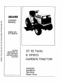
GT 18 TWIN
6 SPEED
GARDEN TRACTOR
Assembly
Installation
Operation
Repair Parts
CONGRATULATIONS
on your purchase of a Sears GT 18
-Garden Tractor
It has been designed, engineered and manufactured
to give you dependability
and performance°
Should
you experience
any problem
you cannot
easify remedy,
please contact
your nearest Sears Service Center. They have
competent,
welt-trained
technicians
and the proper' tools and
parts to service or repair this unit
MODEL
NUMBER
SERIAL
NUMBER
THE MODEL
AND
FOUND
ON THE
TO THE FENDER_
Please read and retain this manual. The instructions wilt enable
you to assemble, operate and maintain
your Tractor
properly. Afways observe the "RULES
FOR SAFE OPERATION
_J
YOUR
NEW
another free manual from www.searstractormanuals.com
GA RDEN
GT
SERIAL
MODEL
NUMBERS
WILL
BE
PLATE
ATTACHED
YOU
SHOULD
RECORD
BOTH
MODEL
AND
SERIAL
NUMBERS
AND KEEP IN A SAFE PLACE
FOR FUTURE
REFERENCE
18
TRACTOR
FEATURES...
CRAFTSMAN
18 HP.
TWIN-CYLINDER
ENGINE.-coot..
running
performance
and long life with ptenty of power to
take on a variety of yard, gardening or snow removal tasks.
ATTACHMENT
VERSATtLITY..-handtes
a large variety of
Sears Yard and Garden Tractor
Attachments
including
44 iNCH MOWER with three "high.lift"
blades to stand
grass up for level cuts
OTHER
SOIL TILLAGE
ATTACHMENTS
including Ptow.
Disc Harrow, Drag Harrow and Cultivator
46 INCH DOZER BLADE levels or moves dirt and gravel or
removes snow.
40 INCH SNOW BLOWER
handles wet, heavy powdery
snow with ease
REAR
GRADER
AND
LEVELER
BLADE
leve_s new
yards, grading lanes, driveways and parking areas,
INTERLOCK
SWITCH SYSTEM--allows
engine to start only
when tractor Clutch-Brake
Pedal is depressed and Attachment
Clutch Switch is in "OFF H position
ALL GEAR TRANSMISSION-six
speeds forward, two reverse
speeds-..to let you select the proper match for the terrain and
the job Automotive-type
differential
helps guard against turf
scuffing.
CONTROL
PANEL-with
Throttle
Choke, Light Switch. Ignition Switch,
Ammeter,
Parking
Brake Lever and Clutch
Switch--conveniently
grouped for ease of use
LIMITED
ON
TWO
ELECTRIC
YEAR
5TART
WARRANTY
RIDING
EQUIPMENT
For two years from date of purchase, when this riding equipment
ismaintained,
lubricated,
and tuned up according to the
operating
and maintenance
instructions
in the owner s manual, Sears wilt repair free of charge any defect in material or
workmanship
in this electric
This warranty
excludes
start riding equipment_
_2
come worn during
blade(s),
normaI
blade adapter(s),
spark plug(s),
air deanm (s) and belt(s),
which
a_e expendable
and be..
use,
_2
This warranty
,,
does not cover:
tire replacement
or _epair caused by punctures from outside objects (such as nails I:horns. stumps, o_ glass};
and
repairs necessary because of operator
abuse or negligence, incIuding
the failure to maintain the equipment
according
..
to instructions
riding equipment
contained
used for commercial
FULL
For 90 days from
workmanship
WARRANTY
MENT
IN THE
This warranty
the date of purchase,
and our testing
SERVICE
UNITED
in the owner's
determines
IS AVAILABLE
STATES.
or rental
90-DAY
manual;
if any battery
included
ON
with
this riding
BATTERY
equipment
wilt not hoid a charge, Sears will
BY CONTACTING
applies only
THE
while
NEAREST
this product
gives you specific legal rights_ and you may also have other
Sears, Roebuck
f_
purposes
WARRANTY
the battery
This warranty
and
and Co., D/698-731A,
proves defective
replace
SEARS
the battery
SERVICE
is in use in the United
rights which
vary from
Sears Tower, Chicago,
in materia$ ol
at no charge,
_x
_2
CENTER/DEPARTStates
state to state
tL 60684
_,
TABLE
RULES FOR SAFE OPERATION
ASSEMBLY
OPERATION
........
BELOW
MAINTENANCE
INSTRUCTIONS
INSTRUCTIONS
.................
4
TROUBLE SHOOTING
INSTRUCTIONS
................
7
REPAIR PARTS .............................
RULES
another free manual from www.searstractormanuals.com
OF CONTENTS
FOR
SAFE
1,, Know the controls and how to stop quickly.
READ THIS
OPERATOR'S
MANUAL
and
instructions
furnished
with attachments°
2. Do not allow children
to operate the machine.
Do not
allow adults to operate it without proper instruction,
3. Do not carry passengers° Do not mow when children end
others are around.
4. Always wear substantial
footwear,. Do not wear loose fitting
clothing that could get caught in moving parts,
5_ Keep your eyes and mnd on your tractor, mower and the
area being cut.. Don t let other interests dtstract you,
6<, Do not attempt
to operate your tractor or mower when
not in the drivers seat.
7, Always get on or off your tractor from the operators left
hand side.
8. Clear the work area of objects (wire, rocks, etc,,) which
might be picke d up and thrown.
9, Disengage all attachment
clutches
before attempting
to
start the engine.
1Q, Disengage power to attachments
and stop the engine before leaving the operator s position.
11o Disengage power to mower, stop the engine and disconnect
spark plug wire(s) from spark plug(s) before cleaning, making an adjustment or repairs,
12, Disengage power to attachments
when transporting
or not
in use,
13o Take all possible precautions
when leaving the vehicle unattended.
Disengage the power-take-off,
lower the attachments, return
drive control
lever to neutral,
shift into
neutral, set the parking brake, stop the engine and remove
the key,,
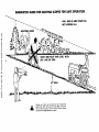
14., Do not stop or start suddenly when going uphitl or downhill Mow up and down the face of slopes (not greater than
15°); never across the face Refer to page 47,
15,, Reduce speed on slopes and make turns gradually to pro.
vent tipping or loss of control,
Exercise extreme caution
when changing direction
on slopes
16 While going up or down slopes, place Gear Shift Control
Lever in Ist gear and Range Shift Lever in 'LO
(Low)
position to negotiate the slope without stopping,
17, Never mow in wet or slippery grass, when traction
is un _
sure or at a speed which could cause a skid,
18. Stay alert for holes in the terrain and other hidden hazards.,
Keep away from drop-offs°
19. Do not drive too close to creeks, ditches and public highways.,
20+, Exercise special care when mowing around fixed objects
in order to prevent the blades from striking them_ Never
deliberately
run tractor or mower into or over any foreign
object_
21,, Never shift gears until tractor comes to a stop_
22. Never place hands or feet under the mower, in discharge
chute or near any moving parts while tractor ormower
are
running,, Always keep clear of discharge chute.
.............
.....................
13
25
27
OPERATION
23.
Use care when pulling loads or using heavy equipment,
a. Use only approved drawbar hitch points.
b., Limit loads to those you can safely control,
c. [)o not turn sharply, Use care when backing.,
d., Use counterweight
or wheel weights when suggested in
the owner s manual
24. Watch out for traffic when crossing or near roadways,
25_ When using any attachments,
never direct
discharge
of
material toward bystanders
nor allow anyone near the vehicle while in operation.,
26° Handle gasoline with care- it is highly flammable°
a. Use approved gasoline containers°
b. Never remove the fuel cap of the fuel tank or add gasoline to a running or hot engine or an engine that has
not been allowed to cool for several minutes after running. Never fill the tank indoors, always clean up spilled
gasoline.
c. Open doors if the engine is run in the garage - exhaust
fumes are dangerous° Do not run the engine indoors°
27° Keep the vehicle and attachments
in good operating
condition, and keep safety devices in place and working.
28,, Keep all nuts, bolts and screws tight to be sure l_he equipment is in safe working condition°
29,, Never store the equipment with gasoline in the tank inside
a building where fumes may reach an open flame or spark
Allow the engine to cool before storing in any enclosure.
30,, To reduce fire hazard, keep the engine free of grass, leaves
or excessive grease_ Do not clean product
while engine is
running.
31, Except
for adjustment;
DO NOT operate Engine if air
cleaner or cover directly
over carburetor
air intake is removed. Removal of such part could create a fire hazard,,
32. Do not operate without
a muffler
or tamper with the exhaust system, Damaged mufflers
or spark arresters could
create a fire hazard. Inspect periodically
and replace if
necessary.
33 The vehicle and attachments
should be stopped
and inspected for damage after striking
a foreign object and the
damage should be repaired before restarting and operating
the equipment.
34° Do not change the engine governor settings or overspeed
the engine; severe damage or injury may result
35° When using the vehicle with mower, proceed as follows:
a. Mow only in daylight or in good artificial lightr
bo Shut the engine off when unclogging chute.
c. Check the blade mounting
bolts for proper tightness at
frequent intervals,
36 Do not operate the mower without
the deflector
shield in
place.,
37. Disengage power to mower before backing up,, Do not mow
in reverse unless absolutely necessary and then only after
careful observation of the entire area behind the mower.
38.
Under normal usage the grass catcher bagm_aterial is stib_t
to deterioration
and wear. It should be checked frequently
for bag replacement.
Replacement
bags should be checked
to ensure compliance
with
the original
manufacturer's
recommendations
or Sl_ecifications.
LOOK FOR THIS SYMBOL TO POINT OUT
PRECAUTIONS.
IT MEANS - ATTENTION!
YOUR SAFETY
IS INVOLVED°
IMPORTANT
BECOME
SAFETY
ALERTI
WARNING
This unit is equipped with an internal combustion engine and should not be used on or near any unimproved forest-covered, brush
covered or grass-covered land unless the engine s exhaust system is equipped with a spark arrester meeting applicable local or state
taws (if any) If a spark arrester is used, it should be maintained ;n effective working order by the operator
In the State of California
the above is required
by taw (Section
4442
have similar
laws apply
lands.
Authorized
_4A_0,
laws. Federal
on federal
S_e your
of the California
Public
Resources
CodeL Other
Service Center for spark arrester muffler
states may
part number
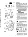
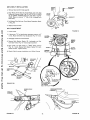
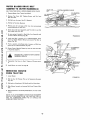
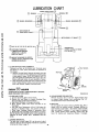
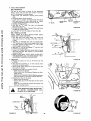
ASSEMBLY
VENT
CUT AWAY
CAP
VIEW
BATTERY
TUBE
To assemble
and adjust your Tractor
you
two 7/16"
wrenches,
one 9/16"
wrench
wilt need:
and a utility
knife
NOTE: RIGHT+lAND
(R.H.) AND LEFT HAND (Loll.) ARE
DETERMINED
FROM
OPERATOR'S
POSITION
WHILE
SEATED ON THE TRACTOR,
1
BATTERY
CELL
Remove Battery, Steering Wheel, Seat and Bag of Parts,. Cut down
four comers of carton with utility knife, and fold down carton sides,,
Remove Banding holding Mower Deck in place and lower Deck down
to the floor. Turn the Deck over so the Blades are down. Disengage
the Parking Brake and roll the Tractor off the skid Be careful that you
do not step on or roll the Tractor over any carton staples
another free manual from www.searstractormanuals.com
F IG Ut_E 1
READ THE INSTRUCTIONS
INCLUDED
WITH
THE BATTERY ACID CONTAINER.
ALWAYS
WEAR GLOVES, CLOTHING AND GOGGLES TO
HOOD
WASH
HANDS
CLOTHING
IMMEDIATELY
PROTECT
YOURORHANDS,
SKIN
AND EYES. IF
ACCIDENTALLY
IN
CONTACT
WITH
ELECTROLYTE,
BATTERY
COMPARTMENT
DO NOT SMOKE,
FUMES FROM
ELECTROLYTE ARE EXPLOSIVE,
CHARGED
t_ill and charge Battery
(before installing),
"NOTE:
SEI_
DETAILED
INSTRUCTIONS
PACKAGED
WITH
BATTERY VENT CAPS IN BAG OF PARTS.
a, Fil! Battery with electrolyte to bottoms of tubes in cells
(Fig, 1) NOTE: DO NOT OVERFILL.
OVERFILLING
WILL RESULT IN DAMAGE TO TRACTOR
b,_ Check level of electrolyte
after 30 minutes. Add additional electrolyte if necessary° I_OTE: TIGHTEN
VENT
CAPS SECURELY,
c_ Charge Battery at a rate of 6 amperes for' one hour,
d, Neutralize excess electrolyte for disposal by adding it
to four inches of water in a five gallon plastic container,
Stir with a wooden or plastic paddle while adding baking soda until the addition of more soda causes no more
foaming.
..
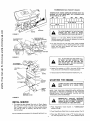
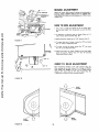
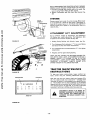
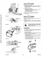
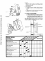
GRILL
FIGURE 2
DO NOT
SHORT
BATTERY
TERMINALS,
BEFORE METAL
INSTALLING
BATTERY, WRISTREMOVE
BRACELETS,
WATCH
BANDS,
RINGS,
ETCo FROM
YOUR PERSON.
3
HEX
BOLTS
BLACK
(NEGATIVE)
CABLE
Install Battery,
a. L_ift hood from rear sides (Fig, 2)
b, Remove tape from Plastic Tray, Make sure Drain Tube
(Fig,, 3) is fastened to Drain Hole in Battery Tray and
Battery Tray is positioned in hole of Battery Support,
c. P_taceBattery in Plastic Tray (Battery Terminals to front
of Tractor ) (Fig., 3)
4,_ Connect
Battery
Cables using: two Hex Botts, two Fiat
Washers, two Lockwashers and two Hex Nuts (shown full
size below) found in Bag of Parts,
u[
Il l/lllIllIIll
('1I....
FIGURE
3
Q
NECTED
TO PREVENT
SPARKS
POSITIVE FIRST
TERMINAL
MUST BE
CONFROM ACCIDENTAL GROUNDING.
a, Connect RED Battery Cable to Positive (+) Battery Ter =
minal with Hex Bolt, Flat Washer, Lockwasher and Hex
Nut (Fig° 3). Tighten securely.
b_ Connect BLACK Ground
Cable to Negative (.) Battery
Terminal
with remaining
Hex Bolt, Flat Washer, Lock.
washcr and Hex Nut (Fig,, 3), Tighten securely.
_. tnstalf
Battery
using:twoInt,/Ekt,Lockwashers,
Nuts (shown full
size below)
INTJEXT,
LOCKWASHER
two Wing
and
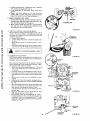
WING
NUT
WING
NUT
INT,/EXT;
=R
NAL
ACCESS
DOOR
another free manual from www.searstractormanuals.com
TERMINAL
GUARD
TERMINAL
ACCESS DOOR
two Battery
Parts.
Bolts and one Terminal
Guard found
BATTERY
in Bag of
a, Using the square hole on one side of the Battery Support
(Fig, 4_ insert one Battery
Bolt, head of Bolt down,
Fasten the Battery
Bolt to the Terminal
Guard using
tnto!Ext, Lockwasher
and Wing Nut as shown in Fig_ 4,
b Assemble the remaining
Battery Bolt to other side of
Battery Support and fasten Terminal Guard to it with re o
maining Int,iExt
Lockwasher
and Wing Nut, Tighten
Wing Nuts securely by hand (Fig,, 4}.
NOTE: USE TERMINAL
ACCESS DOORS (FIGo 4) FOR:
1 Inspection for secure connedtions
(tighten hardware),
2, Inspection for corrosion,
3, Testing battery,
4 Jumping (if required).
5_ Charging (if required),
BATTERY
SUPPORT
FIGURE
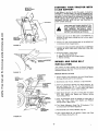
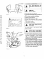
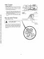
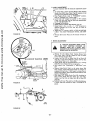
STEERING
WHEEL
4
CAP
._" 2. 3/B" DIA WASHER
EERtNG WHEEL
WHEN NOT IN USE, KEEP TERMINAL
ACCESS DOORS CLOSED.
_
DO NOT START ENGINE UNTIL MOWER
SUSPENSION BRACKET HAS BEEN RELEASED, SEE MOWER AND DRIVE BELT
INSTALLATION, PAGE 8.
6= Remove plastic on Tractor
7., Close Hood,,
BOLT
_
_---_STEERING
_ERING
WHEEL INSERT
COLUMN
Hood.
SEAT
SEAT
8., Install Steering Wheel.
NOTE; POSITION
FRONT WHEELS FORWARD,
a, Remove Hex Bolt, Lockwasher and 2- 3/8 _t Dia Washer
from Steering Column (Fig. 5),
bo Position Steering Wheel over Steering Wheel Insert_
co Secure Steering Wheel to Steering Column using Hex
Bolt, Lockwasher and 2- 3/8" Dia. Washer (Fig 5),
d Snap Steering Wheel Cap in place on Steering Wheel.,
Steering WheeJ Cap found in Bag of Parts,
9., Install Seat,,
a Remove cardboard from Seat Pan,,
ADJUSTMENT
BOLTS
SEAT
SWITCH
\
b o Place Seat on Seat Pan° Screw Adjustment
Bolts,
Lockwashers and Flat Washers into Seat (Fig,, 6), Adjustment Bolts, Lockwashers and Flat Washers found
in Bag of Parts. Tighten finger tight°
c. Place Seat in operating position,, Sit on the Seat and
press Clutch-Brake Pedal all the way down,, If operating
position is not comfortable,
adjust Seat.,
d, Raise Seat. Use 9/16"
wrench to loosen Adjustment
Bolts (Fig 6L When adjusted for comfortable operation,
tighten Adjustment
Bolts securely,,
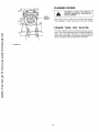
FUEL
TANK
CAP
FIGURE
.5
_
'
6
REC(_MMENDED SAE VISCOSITY GRADES
TEMPERATURE RANGE EXPECTED BEFORE NEXT OIL
CHANGE° ALL OILS MUST MEET A.PJ,. SERVICE CLASSIFICATION SD, SE, OR 5F_
-20°
0°
32 °
60 °
80 °
100°
..........
11II1
another free manual from www.searstractormanuals.com
30 OR 10W-30 ....
DIPSTICK
TO AVOID DAMAGE TO THE STARTING
SYSTEM, USE SAE 5W30 OIL WHEN
THE TEMPERATURE FALLS BELOW 32 O,
ENG INE
FtGURE 7
'
A
' CLUTCH/BR KE"
Capacity is 1 - 112 quarts, NOTE: DO NOT OVERFILL,.
Dipstick assembly must be securely tightened into tube at
all times when engine is operating.
_
,,PARKING BRAKE
"_"ENGAGED"
POSITION
2. FIll Fuel Tank {Fig 6). Use fresh, dean, regular unleaded
automotive
gasoline, (Use of leaded gasoline will increase
carbon
and lead oxide deposits
and reduce valve life}.
Capacity is 3 = 1/2 gallons
"C UTCH",O IT,O,\'ARKING
°,AK
FIGURE 8
CLUTCH SWITCH
GNITION
3..
-
FILL TO BOTTOM
OF GAS TANK FILLER NECK.
DO NOT OVERFILL
WIPE
OFF ANY SPILLED
OIL OR FUEL.
DO
NOT STORE, SPILL OR USE GASOLINE
NEAR AN OPEN FLAME
Tire pressure to
LEARN
YOUR
AREA°
FIGURE 9
SERVICE
with oil Check Engine
ground, Wipe Dipstick
a few seconds, remove
add Oil until "FULL t
1 Place Attachment
position (Fig,,9_.
2. Push Clutch-Brake
ENGINE
IS SHIPPED
and 10 PSi in rear
STOP AND REVERSE
IN A LARGE,
OPEN
WITH INTERLOCK
OF THE TRACTOR
CLUTCH
OR THE
IMMEDIATELY
REPLACE
SWI'I;CHES
THAT ARE NOT IN PROPER WORKING
ORDER. DO NOT ATTEMPT TO DEFEAT
THE PURPOSE OF THESE SWITCHi=So
t.. This engine has been shipped filled
Oil Level with Tractor
on level
(Fig.. 7) clean, screw it n tight for
and read Oil Level If necessary,
mark is reached.
NOTE:
TO START,
TRACTOR
NOTE:
THIS TRACTOR
IS EQUIPPED
SWITCHES
TO PREVENT
STARTING
ENGINE
WHILE
THE ATTACHMENT
TRACTOR
CLUTCH
1S ENGAGED.
GEAR SHIFT
CONTROL
LEVER
INITIAL
14 PSi in front
WITH
SUMMER
WEIGHT
OIL
Clutch
Pedal fully
Switch
in "DISENGAGED"
into brake position
(Fig
8)_
3. Place Gear Shift Control
Lever in "N" neutral, star1: positier, and Range Shift Lever in "N" neutral position (Fig.. 9).
4o full L;noke out (Pig. 9_o
5_
Move Throttle
Control
to middle
position
NEVER PLACE YOUR HANDS OR FEET
IN OR UNDER ANY POWERED ATTACHMENT OR NEAR ANY MOVING PART
WHILE TRACTOR OR ANY POWERED
ATTACHMENT IS RUNNING
(Fig, 9).
6, Turn Ignition Key to '_START"
position until Engine starts
(Fig, 9), NOTE;
DO NOT RUN STARTER
CONTINUOUSLY
FOR MORE THAN
FIFTEEN
SECONDS PER
M1NUTE_ if engine does not start after several attempts,
move Throttle
Control ?o 'IF" (fast) position,
wait a few
minutes and try again,
DO NOT OPERATE THE MOWER WITHOUT THE
DEFLECTOR
SHIELD
IN
PLACE
The first time you start the engine, it will take extra cranking time to move fuel from tank to the engine°
NOTE:
ALLOW
ENGINE
TO WARM UP FOR A FEW
another free manual from www.searstractormanuals.com
MINUTES
BEFORE
OR ATTACHMENT,
7
ENGAGING
CLUTCH
NOTE: A SPARK ARRESTER
MUFFLER
(PAGE 30) IS
AVAILABLE
AS AN ACCESSORY
PART FOR YOUR
TRACTOR,
CHECK LEGAL REQUIREMENTS
IN YOUR
AREA.
OF TRACTOR
When restartin_l a warm engine, move Throttle Control midway between _S" (stow) and "F '1 (fast) position.
C%oke
may not have to be used.
OPERATION
BEFORE DRIVING THE TRACTOR, INSTALL MOWER OR REMOVE MOWER
SUSPENSION BRACKET.
STOPPING
10= B'e sure blades and engine have stopped
hands or feet near the blades,
1t, Remove key when taaving maehine_
TRACTOR
position,
Move Throttle Control to "S" (slow) position,
Turn ignition Key to "OFF"
position,
Never use Choke to
stop Engine,
REMOVE
TOR
TO
USE,
INJURY
I, Read owners manual,
2. Know location and function of atl controls,
3_ Keep guards, safety shields and switches in p]ace and working,
4. Remove objects that can be thrown by blades.,
5. Do not mow when children and others are around,
6, Never carry children or passengers,
7., Always look behind machine before backing,
8. Do not mow where machine can tip or slip.
9. If machine stops going uphill, stop blade and back slowly
down,
before
placing
mid*
2. Push Clutct_,Brake
Pedal down firmly (Fig 8)., Move Gear
Shift Control
Lever to desired gear and Range Shift Lever
to "LO" (Low) position (Figr 9).
3, Release Clutch-Brake
or rearwarll movement.
Pedat
SLOWLY
to
start
forward
4o tf _qround travel is too slow, move Throttle
Control
to
"FtT (fast) position or press Clutch-Brake
Pedal and shift
to a different gear,
NOTE:
BRING
TRACTOR
TO COMPLETE
STOP BEFORE
SHIFTING
GEARS.
ALWAYS
SELECT
A
GROUND
TRAVEL
SPEED THAT WILL SUIT THE TERRAIN AND THE ATTACHMENT
BEING USED,
LEAVING
TRACUNAUTHORIZED
YOUR
TRACTOR
For pushing or towing your tractor, place Gear Shift Control
II
/1
_ ,
Lever and Range Shift Lever to
N neutraf pos=tJon (Fig. 9).
NO3_E: DO NOT TOW YOUR TRACTOR
FASTER
THAN
SIX MILES PER HOUR,
TRACTOR
NOTE: THIS TRACTOR IS EQUIPPED WITH AN OPERATOR
PRESENCE SENSING
SWITCH,
ANY ATTEMPT
BY THE
OPERATOR TO LEAVE THE SEAT WITH THE ENGINE RUNNING AND THE ATTACHMENT
CLUTCH ENGAGED
WILL
SHUT-OFF THE ENGINE.
1_ With engine running and warm, place Throttte
Control
waybetween
S (slow) and
(fast) postton,
KEY WHEN
PREVENT
TRANSPORTIING
1., Choose
hills.
OPERATIION
TRACTOR
1., Push Clutch-Brake
Pedal into "BRAKE"
positiom
2,, Place Parking Brake Lever in "ENGAGED"
position
and
release pressure from Clutch-Brake.
Pedal should remain
in brake position,
NOTE: MAKE SURE PARKING BRAKE
WILL HOLD TRACTOR SECURE.
3 Move Shift Control Lever to "NEUTRAL"
position,
4. Place Attachment
Clutch
Lever
in "DISENGAGED"
5
6,
CAUTION
TO AVOID
YOUR
the
OPERATOON
lowest
gear
BEFORE
DO NOT DRIVE
ON
starting
H0aLS
up
or down.
UP OR DOWN HILLS
WITH DO
SLOPES
THAN ANY
15 ° ,
AND
NOT GREATER
DRIVE ACROSS
SLOPE, REFER TO PAGE 47°
2_ AVOID
STOPPING
OR SHIFTING
a., if slowing
is necessary,
to middle position,
move
ON H ILLS,,
Throttle
Control
Lever
LEAVE
ENOUGH
ROOM
WHEN
STOPPING
AND
STARTING
TO
ALLOW
SLIGHT TRACTOR
ROLL DOWNHILL
AS
CLUTCH-BRAKE
PEDAL
MOVES
THROUGH
CLUTCH POSITION,,
bo If stopping is absolutely
Pedal quickly
to brake
Brake.
necessary, push Clutch-Brake
position
and engage Parking
c. To restart your tractor, make sure tractor is in tst gear
and that you have allowed room to roll slightly downhill, Disengage Parking Brake and release Crutch, Brake
Pedal SLOWLY to start tractor forward movement.,
7 _ 3- Make all turns slowly
STARTING
YOUR
A LOW
BATTERY
NEGATIVE
(BLACK CABLE)
TERMINAL
TRACTOR
WITH
If your Battery is too low to start the engine, it shouid be
recharged_ If "Jumper Cabfes" are used for emergency starting follow this procedure: NOTE: YOUR TRACTOR IS EQUIPPEDWITH A 12 VOLT NEGATIVE GROUNDED SYSTEM, THE
OTHER VEHICLE MUST ALSO BE A 12 VOLT NEGATIVE
GROUNDED SYSTEM,. NOTE: DO NOT USE TRACTOR TO
START OTHER VEHICLES+
_RY
another free manual from www.searstractormanuals.com
LEAD-ACID
BATTERIES
GENERATE
EX+
PLOSIVE GASES. KEEP SPARKS, FLAME,
AND
SMOKING
MATERIALS
AWAY
FROM BATTERIES.
ALWAYS WEAR EYE
PROTECTION
AROUND
BATTERIES,
Connect each end of the RED cable to the POSITtVE
(+)
terminals
of each battery
(taking care not to short against
chassis) (Fig,. 10),
POSITIVE
(RED CABLE)
TERMINAL
2
Connect one end of the BLACK cable to the NEGATIVE
(-) terminal of fully charged battery,
FIGURE 10
Connect the other end of the cable to the L+H,, Side Panel
Bolt (Fig. 8),. NOTE: KEEP AWAY FROM GAS TANK AND
BATTERY
4,
SUSPENSION
Disconnect cables in reverse order:
a L H+ Side Panel Bolt (Fig, 8)_
b.,
Negative terminal of fully charged battery.
c, Positive terminals.
MOWER
BRACKET
AND
DRIVE
BELT
IN STALLATION
Your tractor has been shipped with the Mower Suspension
Bracket banded to the frame, Remove bands and lower Mower
Suspension
FIGURE
Bracket
(Fig+ 11 )+
11
MOWER
ATTACHMENT
HANDLE
|GHEST _'
POSITION
DEPTH
ADJUSTMENT
KNOB
INSTALLATION
1+ Remove banding from Suspension Arms and Gauge Wheelso
Set Gauge Wheels aside for later assembly.
\
2. Slide Mower
ATTACHMENT
HANDLE
3o
_"LOWEST"
POSITION
under Tractor,
Slide Front Suspension
tain with Release Pins
Knob counterclockwise
ment Handle forward to
5_
RELEASE
6_
FRONT
SUSPENSION
BRACKET
to right hand side.
Brackets into Mower Brackets, Re(Fig. 12), Turn Depth Adjustment
( ('-", } until it stops. Push Attach*
lower mower to ground,
4+ Slide Studs through
Lift
(Fig,
12A)+ Retain
with
found in Bag of Parts,
KET
Deflector
Links on both sides of Tractor
Washers and Retainer
Springs
Place the Suspension Arms on Brackets on both
Frame
(Fig.
t2A)+
Retain
with Washers and
Springs found in Bag of Paris.
Turn Depth Adjustment
Knob (Fig. t2)
to remove slack from Mower Suspension+
sides of
Retainer
clockwise
((-_)
7. Roll Drive Belt over Primary Mandrel (Fig+ 13)+
8.
t_sert Gauge Wheel Bar into Bracket+,
Pin and Retainer Spring (Fig 14),+
Retain
with
Clevis
FIGURE 12
-8
+
,,,_
DRIVE BELT INSTALLATION
I. Remove Hood and Gritl (see page 24),
2. Place Mower Drive Belt over Clutch Pulley and under Idler
Pulley and Tension Pulley (Fig, 15L NOTE: PULL LEVER
UP TO SWING TENSION
PULLEY
FOR BELT CLEARANCE,, Make sure narrow "V j' side of Belt is engaged with
each Pu{ley,
3, Pull Mower Drive Belt over Front
et (Fig. 16)o
Mower
RETAINER
GAUGE
WHEEL
BAR
Suspension
SPRING
GAUGE
WHEEL
\
BRACKET
Brack-
4o Replace Hood and Grilt,
another free manual from www.searstractormanuals.com
BELT
CLEVIS
PIN
ADJUSTMENT
FIGURE 14
1.. Lower mower
2,, If dimension "A" on Idler Bracket Assembly measures I/4"
or less, Mower Drive Belt must be adjusted (Fig. 15- insetL
3
Disengage Attachment
Clutch
4.
Remove, Bolt, Washer, Washer (2)_ Lockwasher
and
from Idler Pulley (Fig_ 15- inset) (original position),
CLUTCH
FULLEY_
Switch,
MOWER
ORIVE
BELT
Nut
5. Place V,Belt and Idler Pulley in "NEW"
Pulley position
(Fig., 15 - inset). Replace Bolt, Washer, Washer (2), Lockwasher and Nut Tighten securely
6. Check V-Bett
for proper
installation
IDLER
ILLEY
TENSION
PULLEY
on al! Pulley Grooves
IDLER
BRACKET
ASSEMBLY
_P'
FIGURE
15
PULL FORWARD
TO LOOSEN BELT
FOR EASIER
BELT INSTAL LATt ONj_I_"
FIGURE 12A
MOWER
BELT
MOWER SUSPENSION
BRACKET
DRIVE
PRIMARY
MANDREL
MOWER
DRIVE BELT
FIGURE
'13
- 9-
FIGURE
16
MOWER
ADJUSTMENT
Adjust the mower' while tractor is parked on levet ground or
driveway, NOTE:
MOWER SHOULD
BE IN LOWEST CUTTING POSITION,
Make sure tire pressures are 14 PSi in front;
10 PSi in teat,,
ION
ATTACHMENT
HANDLE
SIDE
H,_IRPIN
CLIP
:1
TO SIDE
1_ Use a ruler to make
are the same height
ADJUSTMENT
sure Flanges at rear of mower deck
from the ground on each side (Fig,
another free manual from www.searstractormanuals.com
t9),
2. If adjustment
side of tractor
is required, snap out Access
above Foot Rest (Fig, 18),.
3o Move Attachment
T.,NT.............
"UP"
position
"B"
and screw
5o To lower ieft side of mower, loosen
Nut "A" up on Adjustment
Rod,
Nut
r'B"
and screw
6_ Adjust until both rear mower flanqes
above the ground, Tighten
Nuts
A
Snap Access Cover in place.
are the same height
and
B securely.
TO
REAR
ADJUSTMENT
Move Attachment
Handle to futl "UP"
positior_
(Fig. 17),
After leveling side to side, measure R.Ho Flanges at FRONT
AND REAR
OF MOWER,. The RH. Front
Flange should
measure 3/4"
tower than the RH
Rear Flange (Fig° 19),
If adjustment
is required,
follow
procedure below.
18
FRONT
FLANGE
FLANGE
FLANGE
.19
o __ -
17).
i----'--
............
o ......
,,u::.
FIGURE
(Fig
4, To lower tight side of mower,
loosen Nut
Nut "A" down on Adjustment
Rod,
FRONT
FIGURE
Handle to futi
Cover on L,H.
- 10 -
;_
IU
r,,/_loC
rriul_t|
Ur
|VI_.,IVVr'M
Loosen Nuts "D".
Scre+w Nuts _iC" up onto Suspension
Arms (Fig. 28). NOTE: SCREW NUTS "C" ON BOTH
SUSPENSION
ARMS THE SAME NUMBER
OF TURNS
SO MOWER WILL REMAIN
LEVEL
Tighten Nuts "D"
securely,
2., TO LOWER FRONT OF MOWER
Loosen Nuts "C _. Screw Nuts "D" down Suspension Arms,
NOTE:
SCREW
NUTS
"D"
THE SAME NUMBER
OF
TURNS
SO MOWER
Nuts "C _ securely.,
WILL
REMAIN
LEVEL
NUT
"D"
Tighten
another free manual from www.searstractormanuals.com
3o With mower deck at desired height, set Gauge Wheels (Fig_
17) to lowest position without
touching the ground_
Use Adjustment
Handle to set mower at the approximate
cutting height you need. Use Clevis Pins (Fig,, t7) to set gauge
wheels at lowest point without
touching the ground.
NUT
"D"
SUSPENSION
ARMS
FIGURE
MOWER
20
OPERATION
When ready to mow, lower Attachment
Handle {Fig. 21)
to preferred
mower height, Select a gear that allows mowing
at full throttle.
This allows the mower blades to lift and cut
the grass efficiently
ATTACHI_NT
HANDLE
MOWER ENGAGEMENT
Pull Clutch Switch {Fig. 22) out and up to engage clutch. There
will be an engine hesitation as the clutch engages. NOTE: THIS
TRACTOR IS EQUIPPED WITH AN OPERATOR PRESENCE
SENSING SWITCH. ANY ATTEMPT BY THE OPERATOR TO
LEAVE THE SEAT WITH THE ENGINE RUNNING AND THE ATTACHMENT
CLUTCH
ENGAGED
WILL
SHUT-OFF
THE
ENGINE,
DEPTH ADJUSTMENT
Fine adjustment
of mower height is controlled
by the Depth
Adjustment
Knob, Turn clockwise
(_)
to raise mower Turn
counterclockwise
(_)
to lower mower (Fig, 22)
FIGURE 2'1
CLUTCH SWITCH
'*ON" POSITION
_
CLUTCH
SWITCH
"OFF"
POSITION
DEPTH
ADJUSTMENT
KNOB
FIGURE 22
iNNER
t i
HANDS
NEVER
ER.
another free manual from www.searstractormanuals.com
'ii, ' L_ ----
FROM UNDER
gEELECTOR.
MOWKEEP
CAUTION INJURY
FIGURE 23
F,-.........
:L
AND FEET
RF.JNOVE
TO AVOID
DEFLECTOR
/t
Use the Runner on the right hand side as a guide; the blade
cuts approximately an inch outside the runner_,
,,/
':!I
ti,
1. Read owners manual,
2o Know location and function of all controls,.
3. Keep guards, safety shields and switches in place and working.
4.. Remove objects that can be thrown by blades.
5_ Do not mow when children and others are around.
6, Never carry children or' passengers.
7, Always look behind machine before backing,
8o Do not mow where machine can tip or slip.
9= If machine stops going uphill, stop blade and back slowly
down,
10,, Be sure blades and engine have stopped
before placing
hands or feet near the blades.
11_ Remove key when leaving machine.
MOWER
EXCEPT
WHEN
SITTING
ON
NEVER ENGAGE ("ENGAGE"
POSITION)
TRACTOR
SEAT,,
L
FIGURE
TIRE
CHAINS
CANNOT
HOUSING ATTACHED.,
24
DEPTH
ADJUSTMENT
KNOB
BE
USED
READ THE "RULES
TION"
CAREFULLY
ING YOUR MOWER,
WITH
THE
MOWER
FOR SAFE OPERABEFORE
OPERATREFER TO PAGE 3.
PLUNGER
12_ Use Attachment
_ATTACHMENT
HANDLE
Handle to lower mower into cutting position= Start mowing at slow speed and increase ground speed
by increasing throttle
as conditions
wilt permit_ Average
cutting height is approximately
2 - 1/2 to 2 _ 3/4 inches.
Height of cut can be adjusted
by means of the Depth
Adjustment
Knob (Fig, 25), Turn Depth Adjustment
Knob
(clockwise
(/'-'_) or counterclockwise
(f'_)
to match preselected Lift Control Lever mowing height°
13 Drive so that clippings
are discharged onto the area that has
been cut. Have the cut area to the right of the machine.
This will result in a more even distribution
of clippings
and more uniform
cutting_ When mowing large areas (Fig,
24), start by turning to the J'ight so that the clippings will
be discharged
away from shrubs, fences, driveways,
etc_
After two or three rounds, mow in the opposite direction
making left hand turns until finished, if grass is extremely
tall, it should be mowed twice. The first time cut relatively
high, The second time to the desired height. The left hand
side of mower should be used for' trimming_
FIGURE 25
MOWER MAINTENANCE
mNETRUCTUONS
MOWER CLUTCH
"OFF"
POSITION
another free manual from www.searstractormanuals.com
BEFORE
MAKING
ANY
INSPECTION,
ADJUSTMENT
OR REPAIR: PUSH TRAC*
TOR
CLUTCH-BRAKE
PEDA'-L
COMPLETELY INTO BRAKE POSITION°
MOVE
SHIFT
CONTROL
LEVER
TO NEUTRAL
POSITION.
PLACE PARKING
BRAKE IN
"ENGAGED"
POSITION.
TURN
OFF
MOWER CLUTCH SWITCH (FIG 26),
IGNITION
SHUT OFF THE ENGINE, MAKE ABSOLUTELY
SURE THE BLADES AND ALL
MOVING
PARTS
HAVE
COMPLETELY
STOPPED, REMOVE THE IGNITION
KEY,
DISCONNECT
THE SPARK PLUG WIRES
FROM THE SPARK
PLUGS AND KEEP
WIRES
AWAY
FROM
THE PLUGS TO
PREVENT
INJURY
FROM ACCIDENTAL
STARTING,,
BLADE
PARKING
CLUTCH,*
BRAKE
PEDAL
"BRAKE'"
POSITION
AKE
FIGURE
26
FIGURE
27
CARE
For best results mower blades must be kept sharp. The blades
can be sharpened with a few strokes of a file or on a grinding
wheel, We suggest they be sharpened after every 15 hours of
mowing. Do not attempt to sharpen while on mower,
1. When grinding, care should be taken to maintain blade balance and the blade should be checked for proper balance
before reinstallation
on mower° Unbalanced or bent blade
will cause excessive vibration
when running and eventual
damage to mower
or engine
Replace bent or damaged
blades°
To check Blade balance0 drive a nail into a beam or wall.
Leave about one inch of the straight naif exposed
Place
Center Hote of clean Blade over the head of the nail (Fig.
27A). NOTE,: CENTER
HOLE OF BLADE ON NAIL. IF
BLADE
IS PROPERLY
BALANCED,
BLADE
SHOULD
REMAIN
IN POSITION
SHOWN IN FIG 27A, tFEITHER
END OF THE BLADE MOVES DOWNWARD,
BLADE
IS
NOT BALANCED
AND MUST BE REPLACED
2,, To ensure satisfactory
operation,
it is recommended
that
before the start of each mowing season, the old blades be
discarded and replaced with new blades Mower blades can
be purchased at any Sears Service Center/Departments
and
most Sears Retail Stores=
BLADE
SWITCH
TREATED
HEX HEAD BOLT
HEAT _
GRADE 5
REPLACEMENT
It is not necessary to remove mower from tractor for blade replacement.
By moving Lift Control
[.ever to up (Rear) position will permit access to blades.
1. Remove the Hex Head Bolt, Lockwasher
and Flat Washer
(Fig. 27).
2 Install new blade with SHARP EDGE DOWN and secure
with Flat Washer, Lockwasher and Hex Head Bolt, TIGHTEN SECURELY.,
A GRADE 5 HEAT TREATED BOLT
CAN BE IDENTIFIED
BY THREE
LINES INDICATED ON THE BOLT
HEAD AS SHOWN AT LEFT,,
ALWAYS
USE GRADE 5 HEAT TREATED
BOLTS TO ATTACH
BLADES_ CHECK
BOLTS IN BLADES OCCASIONALLY
TO
MAKE SURE BOLTS ARE TIGHT,
TORQUE BOLTS 30-35
FT, LBS.
DAI LY
MAI NTENANCE
Make sure all nuts on bolts are tight, cotter pins and retainer
springs are secure. Keep blades sharp, Observe all safety precautions, Keep mower well lubricated
13
CLEANING
MOWER
PREVENT
ACCIDENTAL
STARTING
DISCONNECT
SPARK
PLUG WIRES
FORE CLEANING_
POWER
_OFF
CLUTCH
BETO
Water pressure from a garden hose will remove fresh clippings
from underside of mower
Clean mower after each mowing,
POWER
TAKE-
OFF
CLUTCH
another free manual from www.searstractormanuals.com
The Power Take-0ff
Clutch (Fig 29) should provide years of
service. The C_utch incorporates a built in brake that stops the
Pulley almost immediately.
Eventually,
the internat brake will
wear so the mower blades will not stop as recommended.
Adjustment
FIGURE
.....
29
- 14-
should
be made by a Sears Service Technician.
OUTER
BLADES
(CENTER
BELT
TO
ROUTING
DRIVE
OUTER
DECAL
1. Remove Mower
from
2. Remove Top Cover
Idler Arm Bott.,
MANDRELS)
UNDER
Tractor
BELT
MOWER
IDLER
NUT
DECK COVER
ARM
FLAT
(see below).
Self Tapping
Screws,
and
Nut
L,H. MANDREL
SHEAVE
from
CENTRAL
IDLIL_R
MANDREL
SHEAVE
RHoMANDREL
SHEAVE
3. Roll Belt over the top of the R, H. Mandrel,
4. Pull Belt off all other
another free manual from www.searstractormanuals.com
5
Mandrels
Remove any dirt and grass which
around Mandrels and idler Arm,
6. Check Deck Idler Arm Assembly
they rotate freely (Fig, 30)
may have accumulated
and Flat Idler
7,, Be sure spring is hooked in Deck Idler Arm
on bolt in Mower Housing (Fig. 30),,
8
Assembfy
and
FIGURE
30
Install new Belt in groove of LH. Mandrel Sheave, lower
groove of Center Mandrel Sheave and around Flat fd_er as
shown (F_g 30).
9_ From a position at discharge end of mower,
groove of Roll Mandrel Sheave (Fig, 30)
10., Rotate Center Mandrel
is in grooves properly
Reassemble
12, install
WITH
Top Cover to Deck, Tighten
Mower
to tractor
roll Belt into
Sheave by hand to make sure Belt
BLADES WILL
MANDREL
SHEAVE_
ROTATE
11
to see that
CENTER
all Screws secure-
Y
(see page 8)
RELEASE
PIN
\
REMOVBNG
MOWER
FROM
TRACTOR
t,
Lower Mower,
FIGURE
2, Pull the four (4)
(Fig, 31),,
Release Pins out of Suspension
3, Pull back on Attachment
4. Slide
drel.
Mower
forward
5. Raise Attachment
tractor.
NOTE:
Brackets
Lift Handte and lock into place.
and remove
Belt from
Lift Handle. Slide Mower
1F AN ATTACHMENT
OTHER
THAN
Primary
out from
Man°
under
THE MOWER
DECK IS TO BE MOUNTED
ON THE TRACTOR,
THE
AND
R.H. SUSPENSION
ARMS
(FIG
3t) SHOULD
REMOVED
FROM TRACTOR,
LH.
BE
- 15-
3'1
NOTE:
WHEN
OPERATING
TRACTOR
WITHOUT
MOWER;
REMOVE
IDLERBRACKET
FROM
FRONT
OFTRACTOR,
1,PullBeltupthroughIdlerBracket
andoutoftractor_
Use
Lever
toswing
Tension
Pulley
forBeltremoval.
2oRemove
Loekwashers
and Nuts from idler Bracket (Fig.
32).,
STORAGE
IDLER
BRACKET
Remove mower
NUT
another free manual from www.searstractormanuals.com
from
ATTACHMENT
LEVER
for" winter storage. When mower
LIFT
ADJUSTMENT
Due to different
weights of Attachments,
the Attachment
Lift Spring may require adjustment.
The Adjustment
Bolt
is located on rear of tractor top left side (Fig. 33)
NUT
LOCI<WASHER
FIGURE
tractor"
is to be stored for a period of time, clean it thoroughly,
remove all dirt, grease, leaves, etc. Give blades and underside of
housing a good coat of grease or rust preventative.
Store in a
clean dry area.
32
1. Holding
SPRING
BUSHING
TTACH_NT
'SPRING
Spring
Bushing
with
Wrench,
loosen
Jam Nut.
2 Turn Adjustment
Bolt clockwise (f'_)
to extend
and reduce lift effort (for heavier Attachments).,
Spring
3. Turn Adjustment
Attachments).
lighter
Bolt counterclockwise
4. Retighten Jam Nut against Spring
(("_
} {for
Bushing.
NOTE:
DO NOT ADJUST
FOR MAXIMUM
SPRING TENSION WHEN USING LIGHT ATTACHMENTS
SUCH AS A
MOWER.
ADJUST
LIFT
SPRING
TO AID
IN LIFTING
ATTACHMENT
- DON_T OVER
POWER SPRING.
WHEN
REMOVING
ATTACHMENT
ALWAYS
ADJUST
SPRING TENSION
TO ITS LOWEST POSITION.
JAM NUT
FIGURE
WITH
TRACTOR
MAINTENANCE
INSTRUCTIONS
33
To keep your
essary service
DISCHARGING
CHARGING
Each time you start your tractor, check your Ammeter
(Fig..
34). The needle should move towards the + (charging) mark
indicating
the battery is being charged as you operate the tractor. The headlights will not show a discharge on the ammeter
because they are not connected to the battery (they have their'
own electrical source, see page 26). If you have a lift motor
connected
it will show a discharge when being operated.
D C AMPERES
0
tractor
running
better, longer; perform
necusing the following
Maintenance
Schedule=
5
0
5
DISCONNECT SPARK PLUG WIRES TO
PREVENT ACCIDENTAL STARTING BEFORE MAKING ANY INSPECTION, ADJUSTMENT OR REPAIR (EXCEPT CARBURETOR)o
AMMETER
FIGURE 34
_16-
FIRST
1. CHANGE
Changing
break.in
_
HOURS
ENGINE
Oil after
OIL
the first two
residue which
another free manual from www.searstractormanuals.com
NOTE: BE CAREFUL
THE ENGINE WHEN
hours w}|l help eliminate
might be damaging
NOT TO ALLOW
CHANGING
OIL,
to your
DIRT
Engine,
TO ENTER
a, Drain oil with
Engine warm, Remove Hood and Grill
(see page 24)r, Loosen Oil Drain Wing Nut, Catch oil in a
suitab{e container.
Tighten Oil Drain Wing Nut after aI!
oi! has been drained from Engine,,
b,, Refilt Engine Oit. (See chart, page 6)_ Refill capacity
is t - 1/2 quarts
NOTE:
DO NOT OVERFILL
Replace
Dipstick,
ENGINE OIL
DIPSTICK
AND FILL TUBE
L.H. SIDE
G3
DAILY
_o CHECK
OR
ENGINE
EVERY
OIL
0(2)HOURS
LEVEL
DO NOT CHECK ENGINE
W|TH ENGINE RUNNING.
OIL
LEVEL
Several minutes after stopping
Engine, check Engine OiJ
Level with Tractor
on level ground. Wipe dipstick
(Fig
35) clean, screw it down tight for a few seconds, remove
and read Oit Level. If necessary, acid Oil untit "FULL"
mark is reached, (Bee chart, page 6). NOTE:
DO NOT
OVERFILL,
- r17 "
FIGURE
35
VE.V 5.0UnS
(EVERY 15 HOURS IF OPERATING
IN VERY DUSTY CONDITIONS)
another free manual from www.searstractormanuals.com
ENGINE
OIL FiLL
DIPSTICK
FIGURE
1, CLEAN AIR SCREEN
.Air Screen (Fig. 36 andFig. 40) must allow free-flow of air
to prevent Engine damage from overheating. Clean with a
wire brush,or compressed air to remove dirt, chaff, stubborn
_ried gum and fibers.
2_
CLEAN FRONT GRILL
The front Grill (Fig, 2) must allow free flow of air to prevent engine damagefrom overheating,
a. Brush off debris
3=
KUBRtCATE STEERING AND FRONT WHEELS
There are four Grease Fittings on your Tractor (Fig_ 37),
Using a Grease Gun, give each Grease Fitting two shots of
Extreme Pressure Lubricating Grease Amdex No_ 1 or
equivalent (available through your Sears Service Center),
SearsPar1:No, 2557R;
36
4_
OIL PIVOT
POINTS
Place several drops of S_AE. 30 Oil at points
move against each other, especially:
a. Front Axle Pivot=
b, Hood Hinges.
c, Foot Pedal Shaft (both ends)_
do Lift Shaft (both ends)..
e, Steerrng Plate,
SEE LUBRICATION
CHART,
PAGE 19
FRONT
where pares
PIVOT
5, CHECK
a
FRONT SPINDLE
(GREASE FITTING)
|LEFT & RIGHT)
LUBR_ICATE THE.
STEERING
PLATE
IN AREA OF
SECTOR GEAR
_(LEFT
BATTERY
Electrolyte solution level in each Battery Cell should be
even with bottoms of tubes in cells (Fig. 38). Add only
distilled water if necessary.
NOTE: DO NOT OVERFILL.
DO NOT ADD ACID
b. Keep Battery
c, Keep Battery
WHEEL
FITTING)
& RIGHT)
d. Keep Vent
oPen_
e.
Recharge
and Terminals
Bolts tight
Caps tight
at 6 amperes
and
clean, Refe_ to step 8_
small
vent
holes
in Caps
for 1 hour if necessary
KNOB
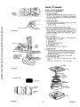
FIGURE 37
COVER
CUT-AWAY
VIEW
PAPER
CARTRIDGE
OIL FOAM
PRE-CLEANER
BATTERY
TUBE
BATTERY
BODY
FIGURE 38
- 18 -
FIGURE 39
another free manual from www.searstractormanuals.com
(_
BOTH
ENDS OF
FOOTPEDALSHAFT
--1_ SAE 30 (SC, SD OR SE) MOTOR
ji
OFL
EXTREME
PRESSURE
LUBRICATING
GREASE
AMDEX NO. ], SEARS
PART NO. 2557R
Q
EFER TO ENGINE OIL SPEC'S.
(UNDER
INITIAL
PREPARATION
IN OWNERS MANUAL)
6. CLEAN BATTERY
AND TERMINALS
Corrosion
and dirt on the Battery
and Terminals cause
the Battery to "leak" power and hinders the operation of
the charger. '
a., Remove Terminal Guard. Remove the battery from the
tractor and wash with four tablespoons
of baking soda
to one gallon of water_ NOTE: BE CAREFUL NOT TO
GET THE SODA SOLUTION INTO THE CELLS. Rinse the
MUFFLER
Battery with plain water, dry and reinstall on Tractor,
b o Clean terminals
and cable ends with a wire brush until
bright. Replace Battery Cables. Coat terminal connections with Vasoline, Replace Terminal
Guard.
.vf.v
AIR
SCREEN
.o..s
(OPERATING
IN DUSTY CONDITIONS
MORE FREQUENT
SERVICING)
MAY
REQUIRE
FIGURE 40
1. CLEAN AIR FILTER
a,, Unscrew Knob (Fig, 39) to remove Cover,
b. Remove Nut and Washer to remove Cartridge
Plate,
Paper Cartridge and Oil Foam Pre-Cleaner.
c. Wash Foam Pre-Cleaner in detergent and water.
d. Rinse, squeeze (rather than twist)
and allow to dry
3o CLEAN ENGINE COOLING FINS
Remove any dust, dirt or oil from Engine Cooling Fins
to prevent Engine damage from overheating (Fig,, 4t)_
Air Guide Covers must be removed (Fig° 40).
thoroughly.
e. Coat with three Tablespoons
of S.A,E. 30 Engine Oil,
squeeze to distribute
evenly, and squeeze out excess,
f. Check Paper Cartridge. Replace if excessively
dirty.
g. Reassemble Paper Cartridge and re-position
on Tractor.
NOTE: NEVER RUN ENGINE WITH AIR CLEANER
REMOVED
AS DIRT
(DUST) WILL
DAMAGE
THE ENGINE.
Do not operate the tractor without
a Muffler (Fig. 40) or
tamper
with
the exhaust system° Damaged
Mufflers
or
spark arresters could create a fire hazard, Inspect periodically and replace if necessary_ If your engine is equipped
with
a spark at'rester screen assembly, remove every 50
hours for cleaning and inspection.
Replace if damaged°
2. CHANGE ENGINE OIL
The best time to drain Engine Oil is at the end of a day's
operation when all dirt and foreign materials are suspended
in the hot Oil. Refer to page 17.
-19-
4, MUFFLER
fv=.v t]@®.ou.s
1.
REPLACE SPARK PLUGS
Replace Spark Plugs at the beginning of each season or
every I00 hours, whichever comes first Gap should be set
at .030 inch (Fig. 42).
another free manual from www.searstractormanuals.com
2. LUBRICATE BALL JOINTS
a._ Move Rubber Boots to expose Ball Joints oh Tie Rods
and Steering Link (Fig. 43)_
b,, Coat Ball Joints with Silicone Spray Lubricant
c. Reposition Rubber Boots,,
3, REPLACE AIR CLEANER
Refer to page 19.
CLEAN AREA
OF ALL DIRT
AND DEBRIS
FIGURE
Evu.Y
41
CARTRIDGE
.o..s
REPLACE IN-LINE
FUEL FILTER
a_ Remove Hose Clamps from Fuel Lines at Fuel Fitter (Fig,
44)4
b. Remove Fuet Filter,
c Place new Fuel Filter in position with fuel line (arrow on
side of Filter in direction
of Fuel Filter} and reinstall Hose
Clamps,
GAUGE
PLUG
FIGURE
PAPER
BE SURE THERE
ARE NO FUEL
LEAKS AND THAT HOSE CLAMPS
PROPERLY
INSTALLED.
42
LINE
ARE
TIE ROD
TIE ROD
BALL
AS NEEDED
1_ Make sure all nuts on bolts are tight and cotter pins are secure, Observe all safety precautions,
Keep Tractor
well
lubricated
(refer to page 18).
JOINTS
,JAM NUTS
STEERING
2_
LINK
BOOT
FIGURE
43
FIGURE 44
are being
Tie
Rod
measure
center to
center to
PRESSURE
RELIEF
VALVE
HOSE
CLAMPS
FUEL
TOE_IN ADJUSTMENT
If any parts in Front Axle or Steering Mechanism
_epiaced, ToeJn adjustment is _equired
a, Loosen Jam Nuts (Fig, 46) at each end of
Adjustment Sleeves_
b. Adjust both Tie Rods so that Tie Rod Joints
9- 5/8" from center to center,
c, On front of front tires measure distance from
center (measurement No, 1),
d On rear of front tires measure distance from
center (measurement
No, 2),
FILTER
- 20-
FIGURE 45
TIE ROD
e, Compare measurements - measurement No. 1'should be
I/8- 1/4 less than measurement No, 2o
fo If not adjust each Tie Rod equally to get correct measurement_
g. Tighten
Jam Nuts making sure Tie Rod ,Joints are
parallel
(180 =) to each other. This adjustment
secures
proper front wheel Toe-In and Steering operation,
3. CHECK
a.
TRANSA:XLE
Remove
THE ROD
OIL LEVEL
Filler Plug (Fig, 47) from
Transaxteo
JAM NUTS
Oil Level
should be even with Filler Plug threads,, Add S.A,E. 30
(SC, SD OR SE) Motor Oil if necessary,
b. Check Pressure Relief Valve (Fig. 45 ._Inset) located on
R,,H. side near top, It should spring completely
closed
when pulled out by hand and released,
STEERING
another free manual from www.searstractormanuals.com
BOOT
FIGURE
4, THROTTLE CONTROL CABLE ADJUSTMENTS
Never attempt to change maximum engine speed -Fhis is
preset at the factroy (3400 _+ 100 RPM) and should only
be change by a qualified service technician
who has the
necessary equipment
a
Remove hood, page 24.,
b
Loosen casing clamp screw until throttle cable is free
to move
c
Move throttle control (on the dash board) to "Fast"
position
d
Pul! throttle cable tight (until swivel is against side of
quarter circle) Fig. 48 Retighten casing clamp screw_
REFER TO "STARTING
THE ENGINE",
LINK
46
"RANSAXLE
ER PLUG
PAGE 6. l
1
5, CARBURETOR
ADJUSTMENT
FIGURE 47
NOTE: Adjust throttle control cable before making any adjustment to carburetor
Air cleaner must be assembled to
carburetor
when running engine
Minor carburetor adjustments may be required to compensate for differences
in fuel, temperature
or altitude. Adjust
the carburetor
fuel mixture as foltows:
a, Gently turn idle mixture valve clockwise
(_}
Fig. 49
until it just ctoses and then counterclockwise
(_--_x)
! 1/2 turns
CAUTION: Valve may be damaged if turned in too far.,
b. Start engine and allow to warm for five minutes
Make
final adjustments with engine running and choke pushed in,
c
Move throttle
control
lever (on dashboard)
to slow
position
d, Hold governor control lever against idle speed screw,
and adjust idle speed screw to obtain 1200 to 1400 RPM
Fig
49.
e, While still holding the governor control lever against idle
stop, turn idle mixture valve slowly clockwise
(f-_,)
(lean mixture)
until speed just starts to stow
f
Turn idle mixture valve back to the midpoint between
rich and lean.
g
f.
Adjust the idle speed screw to obtain 900 to 1200
RPM. Release governor control lever..
Move throttle
control (on the dashboard)
to "FAST".
If engine hesitates or dies. turn idle mixture valve ap _
proximately
1/8 turn counterclockwise
(_'x)
until
engine will accelerate as throttle control is moved from
"'SLOW"
to "FAST".
- 21 -
[THROTTLE
CABLE
GOVERNOR
6. V+BELT ADJUSTMENT
To assuremaximum belt life check belt adju_ment seasonally.
a. To tighten Belt, remove (4) Hex Wo_her Head Tapping
Screws from Shift Cover Plate (Fig. 50} located on top
of tractor frame. Remove the Cover Plate. '
b, Place Parking
Brake
Lever
m
ENGAGED
posEtion+
....
.
Refer
•
4"+
another free manual from www.searstractormanuals.com
if
II
.
•
to
Stopping
r[
,
Your
I_}
Tractor,
page
7+
.
+
c. Loosen Nut A located on outside of R+H. Chassis
Frame (Fig+50),
slideTake-Up
Idler down approximate+
I_
11
ly 1/2" and tighten Nut A ,
d. DisengageParking Brake.
e Check position of Clutch Idler Bracket (Fig. 5t}.
f. Repeat steps b thru e until a 1 + 1/16" dimension is
obtained between top of Pin and top of Frame as
shown in Fig. 51,
g, Tighten Nut "A" securely. NOTE; AFTER ADJUSTING
V-BELT YOU MUST READJUST BRAKE, SEE STEP
6,
h Reinstall Shift Cover Plate and (4) Screws removed in
step a,
u
J
.
t|
FIGURE 50
7. BRAKE ADJUSTMENT
TOP OF
FRAME
IF TRACTOR REQUIRES MORE THAN
SIX FEET STOPPING DISTANCE
IN
HIGHEST GEAR ON A LEVEL DRY
CONCRETE OR PAVED SURFACE THEN
BRAKE MUST BE ADJUSTED.
1., 1116"
TOP OF
PiN
R,H+ SIDE
OF TRACTOR
a. Remove (4) Hex Washer Head Tapping Screws from
Shift Cover Plate (Fig+50}, located on top of tractor
frame. Remove the Cover Plate+
b, Loosen Jam Nut (G) on Brake Rod (B} at Clevis (C)
(Fig+52)+ if you find it difficult to loosenJam Nut (G),
remove Cover Plate in LH+ Frame Rail+
c. Rotate Brake Rod (B) counterclockwise, (F'_} turning
Brake Rod out of Clevis (C) four to six turns,
d Start tractor with Transmission in "NEUTRAL _ posi+
tion_
e+ Depress Brake+Clutch Pedal to the point where Belt
stops moving+ Hold Brake-Clutch Pedal in position by
engagingParking Brake, _f Belt begins to move after engagingParking Brake, depress Brake-Clutch Pedalto next
notch on Parking Brake,
f. Shut engine off, Rotate Brake Rod (B) clockwise by
hand, turning Brake Rod into Clevis {C), until tight+
Tighten Jam Nut (G) on Brake Rod (B) at Clevis (C)
(Fig. 52)+
g. Reinstall Lift Cover Plate and four (4) Mounting Screws,
if Cover Plate was removed in step b it should be replaced,
ENGINE
PULLEY
IDLER
1 + 1116"
NUT"A"
CLUTCH
t
l
TAKE-UP
IDLER +
FIGURE 51
FIGURE 52
+22-
8., V-BELT
REPLACEMENT
BELT REMOVAL
another free manual from www.searstractormanuals.com
The belt on this tractor
is special for this application.
Always
replace with the Sears belt number in the parts
list, It is not necessary to remove mower_
ao Raise hood and disconnect negative ground
battery
cable,
b_ Set parking brake {to get belt slack),
c_ Loosen (do not remove) two Engine Pulley Belt Guide
Bolts and swivel R.H, side of Belt Guide up, Tighten
Loll,, Bolt to hold Belt Guide in position (Fig, 53)..
do Roi! Belt off Enqine Pulieyo
e, Rotl Belt off-'V"
Idler, Fiat Idler and Adjustable
Idler Pulleys (Fig, 54),,
f. Pull Belt off Clutch Pulley - between Pulley and Frame.
Pu!i Belt off Transaxle Pulley.
go Loosen Nut "A j_ on R,H. outside of Frame (Fig, 56).
IDLER
"'V °' IDLER
PULLEY
FIGURE 54
BELT INSTALLATION
NOTE:
UNDER
THERE
IS A BELT
INSTALLATION
LEFT HAND FOOTREST,
DECAL
a_ Push Belt down from Engine Pulley area. Place back
(flat) side of Belt on Flat Idler. (Flat Idler is next to
Frame.}
b, Place Belt on Adjustable
idler and over Clutch Pulley
"V" (narrow} part of Beit should engaqe Clutch Pulley,
c. Piace Belt around Transaxle Pulley, nV" part of Belt
should engaqe Transaxle Pulley_
d,. Make sure 'rv" part of Belt engages "V" Idler (Fig, 54}o
e. Roll Belt over Engine Pulley,
f, Loosen LHo Engine Pulley Belt Guide Bolt and swivel
Belt Guide onto R_H, Bolto Tighten LH,. and R.Ho Bolts
securely (Fig. 55).
g_ Release Parking Brake. NOTE:
WHEN A NEW BELT
HAS BEEN INSTALLED,
YOU MUST CHECK V-BELT
ADJUSTMENT
AND BRAKE ADJUSTMENT
©
ENGINE
BOL"
PULLEY
BELT
°
0 o
9o TIRE CARE
a. Maintain tire pressure in front at t4 PSI and rear tires
at 10 PSI,,
b° Keep tires free of gasoline, oil, or insect control chemi.
cals which can destroy rubber.
ca Avoid stumps, stones, deep ruts and other hazards that
may cause tire damage.
d, Removing front wheel for tire repair (Fig.. 57)
--- Block up front axle securely
-- Remove Hub Cap, Klip Ring and Washers to allow
wheel removal.
-- Repair tire and reassemble,. Replace Washers and snap
Klip Ring securely in axle groover Replace Hub Cap_
eo Removing rear wheel for tire repair,,
--- Block up rear axle securely.
.-- Remove Hub Cap and (5} Hub Bolts to allow wheel
removal.
--- Repair tire and reassembles Replace and tighten Hub
Bolts and Hub Cap securely.
\
\
NUT "A"
BE SEATED.
OVERINFLATION
CAN
WHEN
TIRES, BEADS MUST
CAUSE MOUNTING
A FATAL EXPLOSION.
FIGURE
56
BELT
WASHERS
HUB
CAP
LOOSEN
KLIP RING
FIGURE
53
PULLEY
- 23 -
FIGURE
57
10oFINISH
Keep tractor finish and seat free of gasoline, oil_ insect
chemicals or battery electrolyte. Protect painted surfaces
with automotive type wax,,
WIRE
CONNECTION
11o HOOD
REMOVAL
a,, Lift Hood,
Disconnect
Headlight
Wiring Connection
(Fig. 58)°
b, Unscrew one Screw at rear of each Side Panel (Fig,
58),,
c. Pivot Hood
(Fig., 59).
and Side Panel forward
and tilt
off
tractor
d. To replace, reverse the above procedure.
12,
ELECTRIC CLUTCH ADJUSTMENT
a
Make sure Attachment
Clutch and Ignition Switches
are in the "OFF" position,
b
Adjust the three nylon Iocknuts °'B" until the space
between the Ctutch Plate and rotor measures _012 at
all three slot locations cut in the side of the Brake Plate
another free manual from www.searstractormanuals.com
r
FIGURE 58
(Fig. 60).
NOTE: After installing new Electric Clutch, run Tractor at full
throttle and Engage and Disengage Electric Clutch 10 cycles
to wear
in Clutch
Piate
,,.__ ..O12
l ,I
BRA
FIGURE
NYLON LOCKNUT"B"
59
FIGURE
¢
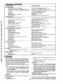
SERVICE
RECORD
FILL IN DATES
AS YOU COMPLETE
REGULAR
SERVICE
._"_.I_._1_
Check Engine Oil Level
page 6}
_1_
Pivot Points (see page 19)
Check.Brake
Operat!on
SERVICE
[_IIPi
Change Engine Oil (see chart,
Lubricate
v
............
_
II_
.....
.....
Clean Air Screen
c,ooo
IV"
Replace Air Cleaner Paper Cartridge
Clean Engine Cooling
1
_1_
Fins
__
I
' • '_"
i
Replace Spark Plug
Check Battery
V
Levet
Check Tire Pressure
II_
I
Replace Fuel Filter
-24-
i..........
DATES
60
TROUBLE
POSSIBLE
SHOOTING
CAUSE
POSSIBLE
WILL NOT START
Clutch-Brake
Pedal in drive position
Attachment
Clutch Switch in "ENGAGED"
position
No gasoline in Fue! Tank or clogged Fuel Line or Fuel
Filter
Blown Fuse
Dead Battery
Defective Ignition or loose Wiring
Spark Plug fouled
another free manual from www.searstractormanuals.com
HARD
TO START
Choked improperly,
flooded
Engine
Clogged Fuel Tank, Fuel Line or Fuel Filter
Spark Plug fouled
Defective Battery
Defective Ignition or loose wiring
Water in gasoline or old fuel
Improper Carburetor
Poor compression
ENGINE
MISSES
adjustment
OR LACKS
ENGINE
improper
gap or wrong type
(Fib 44)
Place Throttle
Control
in fast position
(Fig. 9} and
starter several times to clean out gas
Remove and clean {Fig. 44)
Replace Spark Plug and adjust gap (Fig, 42}
Recharge or replace
Check the wiring and Spark Plugs
Drain Fuel Tank and Carburetor,
use fresh fuel and
replace Spark Plug
Make necessary adjustments
(Fig. 48)
Major engine overhaul
run
Shift to a lower gear or reduce load
Remove and replace (Fig. 44)
Remove and clean
Remove and clean (Fig 39)
Make necessary adjustments
(Fig. 4B)
Clean Air Screen, Cylinder Fins (Fig, 41) and Muffler
Add or change oil (Fig. 35)
Replace Spark Plugs and adjust gap (Fig, 42}
Check Spark Plugs and for any loose wires
Major Engine overhaul
Drain Engine 0il and refill
Remove and clean (Fig° 39)
area
OVERHEATS
Clean Air Screen (Fig. 40)
Add or change oil (Fig, 35)
Clean Cylinder
Fins, rotating
Screen
Remove and clean Muffler (Fig. 40)
Adjust Carburetor
(Fig, 48)
Dirty Air Screen
Low oil level
Dirty Engine
Partially plugged Muffler
Improper Carburetor
adjustment
NO LIGHTS
No Headlight with Light Switch
and engine running
WON'T
Push Pedal into brake posilion (Fig. 8)
Move Switch to "'DISENGAGED"
.position (Fig 9)
Fill Tank with fr_;sh Gasoline. Check Fuel Line
and Carburetor
(clean if necessary)
Check for fault and replace Fuse
Recharge or replace Battery
Check Wiring
Replace Spark Plug and adjust gap (Fig:. 42) .
POWER
Engine overloaded
Clogged Fuel Filter
Clogged Fuel Tank
Partially plugged Air Cleaner
Improper Carburetor
adjustment
Dirt,/Air
Screen
Low oil level
Spark Plug fouled,
Faulty ignition
Poor compression
Gasoline in oil
Dirty Air Cleaner
REMEDY
in "ON" position
CHARGE
Blown Fuse
Defective Battery
Check
Wire
Connections
and Switch.
and
Muffler
Replace
Light
area
Bulbs
Check for fault and replace
Replace
STORAGE
1. FUEL SYSTEM
NOTE: THE USE OF A FUEL ADDITIVE,
SUCH AS STABIL, OR AN EQUIVALENT,
WILL MINIMIZE
THE FORMATION OF FUEL GUM DEPOSITS DURING STORAGE.
SUCH AN ADDITIVE
MAY BE ADDED TO THE GASOLINE IN THE FUEL TANK
OF THE ENGINE, OR TO
THE GASOLINE
IN A STORAGE
CONTAINER°
If Sta-Bil is not used all fuel should be removed from fuel
tank.,
a. Drain fuel tank and carburetor by allowing the engine to
run out of gasoline.
ROTE:
GASOLINE
LEFT
tN
YOUR ENGINE WILL LEAVE GUM DEPOSITS CLOGGING FUEL SYSTEM.
b. Dispose of gasoline if not to be used° NOTE: GASOLINE
STORED
FOR SEVERAL
MONTHS
LOSES
ITS VOLATILITY
(ABILITY
TO BURN
EFFECTIVELY),.
2, ENGINE OIL
Drain (with engine warm) and replace with clean engine oil.
(See chart, page 6).
3o CYLINDERS
a.. Remove Spark Plugs.
b. Pour one ounce of oil through spark plug holes into cylinders.
c.. Turn
Ignition
Key to "START"
position
for a few
seconds to distribute
oil
d. Replace with new Spark Plugs=
4. BATTERY
a,. Remove battery
if tractor is not used regularly during
winter months,. Store in cool, dry place {above 50=F,)o
CAUTION:
A DIRTY
BATTERY
CAN
RUIN
A
FLOOR
CLEAN
BATTERY
BEFORE
STORAGE°
b o Re-charge each month at 6 amps for 1 hour if necessary,.
NOTE:
BATTERIES
NOT 1N USE FOR SEVERAL
MONTHS AND NOT KEPT FULLY CHARGED, PRODUCE
SULPHATE. DEPOSITS ON PLATES WHICH CANNOT
BE REMOVED BY RECHARGING..
5. GENERAL
CLEANING
Clean engine, battery,
6, STORE IN A CLEAN
seat, finish, etc, of all foreign
AND DRY AREA.
matter_
Sears, Roebuck and Co. reser'_es the right to make any changes
in design or improvements without imposing any obligation
* 25-to
install the same upon its items heretofore manufactured.
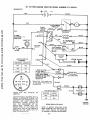
GT 18 TWIN
GARDEN
TRACTOR--MODEL
NUMBER
917o255915
SCHEMATIC
12V
.__
...........
o,,,.o,,,
I
I
RED
another free manual from www.searstractormanuals.com
L
I
,, ,_..................
CLUTCH/BRAKE
:O I
(PEDAL UP)
POWER
TAKE-OFF
SWITCH
,UTCH OFf
RED
WHITE
D
I
'
=
WHITE
Ei
I
!
I
I
I
SOLENOID
RED
2 TURNS
CLOCKWISE ((-_)
FROM FUSE
ELECTRIC
BLACK
CLUTCH
L_.
AMMETER*
RED
M
FUSE
BLACK
BLACK
IGNITION
SWITCH
RED
I
I
I
SEAT SWITCH
{NOT OCCUPIED)
30 AMP
BLACK
i
I
L
G
IGNITION
UNIT
IGNITION
SWITCH
STD365402
POSITION
BLACK
SPARK PLUGS
CIRCUIT
RED
OFF
M-G
ON
B_L
START
BLACK
5 AMPS DC (POSo|
22 VAC
5 AMPS DC
NOTE: WITH ENGII_
B-S
RUNNING @ 3600
BATTERY IN-LINE
LIGHTS OFF
DIODE
ASSEMBLY
ENGINE COIL
(ALTERNATOR)
RPM,
*INDUCTIVE
TYPE. WIRE COILED AS SEEN FROM BACK OF
DASHBOARD.
ORANGE
BROWN
PTO SWITCH
LIGHTS
WILL
AMMETER_
NOT
REGISTER
ON
POSITION
_
......
BLUE
HEADLIGHTS
CIRCUIT
.........
,
OFF
YOUR TRACTOR
IS EQUIPPED
WITH A
SPECIAL
ALTERNATOR
SYSTEM.
THE
LIGHTS ARE NOT CONNECTED
TO THE
BAT-FERY,
BUT
HAVE
THEIR
OWN
ELECTRICAL
SOURCE.
BECAUSE
OF
THIS,
THE
BRIGHTNESS
OF
THF
LIGHTS
WILL
CHANGE
WITH
THE
ENGINE
SPEED. AT IDLE SPEED THE
LIGHTS
WILL
DIM. AS THE ENGINE
IS
SPEEDED
UP, THE
LIGHTS
WILL
BECOME THEIR BR IGHTEST.
4021J
LIGHT
SWITCH
B+E, C+D
ON
B+A
WIRING
INSULATED
CLIPS
NOTE:
tF WIRING
INSULATED
CLIPS
WERE
REMOVED
FGR SERVICING
OF
UNIT,
THEY
SHOULD
BE REPLACED
TO PROPERLY
SECURE YOUR WIRING..
26 -
CHASSIS
GROUND
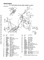
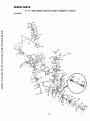
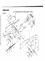
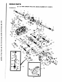
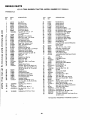
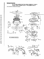
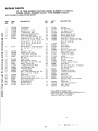
REPAIR
PARTS
GT
18 TWIN
GARDEN
TRACTOR--MODEL
NUMBER
917.255915
ELECTR ICAL
another free manual from www.searstractormanuals.com
A
5O
43
44
38
A
E
B
t3
C
14
16
18
D
48
3
KEY
NOo
t
2
3
4
5
6
7
8
9
PART
NO.
14
105613X
STD365402
! 1151000
3258J
121 t11X
108240X
9138R
7603J
100541K
109596X
109081X
10090400
STD541225
t7190408
15
16
17
18
19
20
21
22
23
24
25
26
27
104445X
71031008
73951000
106315X
t05387X
4152J
108824X
74610628
ST0523707
4207J
11050500
402!J
4022J
10
11
12
13
2
•_
6
25
U
DESCRIPTION
Key Set
Switch- tgnition
Washer- Lock. Int. Tooth 5/8
Nut- Hex 5/8 _32
Ammeter
Switch - Light
Batter_'
Tray - Battery
Tube - Drain
Clamp- Hose
Solenoid
Washer- Lock 1/4
*Nut- Hex -Jam 1/4 -20
Screw - Hex Washer Thread Cutting
1/4- 20 x 1/2
Switch - Interlock, Clutch Pedal
Screw - Hex Washer No. I0- 32 x 1/2
Nut - Keps No. 10- 32
Diode Assembly
Harness - Wire
Bulb- Headlight
Fuse- 30 Amp
Bolt- Hex 3/8- 24 x 1 - 3/4
"Bolt - Hex 3/8- 16 x 3/4
Cable- Ground
Washer- Lock - Ext_ Tooth 5116"
Switch * PTO
Nut- Hex
E
KEY
NOo
PART
NO,
DESCRIPTION
28
29
30
31
33
34
35
36
37
38
39
40
41
42
43
44
45
46
4799J
7 t9J
51J
5115J
t0955OX
106367X
108t 70X
19132203
Cable - Battery
Cover - Terminal
Cover _Terminal
Cable- Starter
Clutch - Electric
Spacer- Clutch
Stop - Clutch
Washer
48
49
50
- 27 -
STD551137
72240460
11030400
STD541625
102476X
STD522507
ST055t025
STD541025
ST0551125
110017X
49
*Washer. Lock 3/8
Bolt- Carriage 1/4- 20 x 7 - 1/2
Washer- Lock. IntJExt,, Tooth 1/4
*Nut-Wing
1/4- 20
Guard. Terminal
*Bolt- Hex 1/4 - 20 x 3/4
*Washer 9/32 x 5/8 x 16 Ga.
* Nut- Hex 1/4 - 20
*Washer o Lock 1/4
Harness - Ignition
109869X
71031008
109748X
10t539X
120383X
Switch,
Seat
Screw - Hex Washer
*STANDARD
HARDWARE-PURCHASE
Relay Assembly
Sheet, Instruction,
Manual _ Owners
Hd. 10 - 32 x 112
Tractor
t5 ° Slope
LOCALLY
REPAIR
PARTS
GT 18 TWIN
CHASSIS
AND
GARDEN
TRACTOR--MODEL
ENCLOSURES
another free manual from www.searstractormanuals.com
61
66
67
3O
33
............
28 -
NUMBER
917.255915
REPAIR
PARTS
another free manual from www.searstractormanuals.com
GT 18 TWIN
CHASSIS AND ENCLOSURES
GARDEN
TRACTOR--MODEL
KEY
NOD
PART
NO.
t
2
3
5
9
10
11
12
13
14
15
16
1t0053X
109866X
105529X
73680500
110378X
73680600
109593X
106202x
105801X
STD523707
105567X
17490608
Seat
Pan - Seat
Bolt - Shoulder
Nut- Lock 5/16- !8
Bracket - Pivot Seat
Nut- Lock 3/8- 16
Fender
Refector - Tailfight
Decal
* Bolt - Hex 3/8- 16 x 3/4
Decal. Chassis
17
17490616
18
19
20
21
22
23
24
25
26
27
28
29
30
31
32
33
34
35
36
37
38
39
40
105511X
105514X
1055!2X
19132012
105531X
105509X
106020X
109462X
106082X
6999R
7834R
7833R
105465X
I05466X
105464X
110892X
110893X
7982J
74760716
73680700
108403X
105562X
108410X
Screw - Hex Washer Thread Roiling 3/8
-t6xl
Strap - Fender
Clamp - Spring
Spring- Compression
Washer 13/32 x 1 - 1/4 x 12 Ga.
Nut - Push
BracketFender
Tank - Fuel
Cap- Fuel
Pad - Spacer
Clamp- Hose
Line- Fuel
Line- Fuel
Footrest - L.,H,
Pad - Footrest
FootrestR H.
Rail- Frame- RH, "*
Rail - Frame- LH
**
Drawbar
Bolt - Hex 7/'16- 14 x 1
Nut- Lock 7/16 - 14
Panel - Side o R,H,
Decal
Panel - Side - L.H,
A
DESCRIPTION
B
Screw- Hex Washer Thread Roiling
3/8- t6 x 1/2
C
D
5
(_
77
lo
E
F
I_
(_
NUMBER
917.255915
KEY
NO.
PART
NO.
DESCRIPTION
41
42
43
44
48
49
50
51
52
54
55
108508X
108509X
106013X
I06067X
105528X
108512X
t08513X
I06003X
106004X
106006X
I06005X
Bracket - Pivot- Frame. RHo
BracketPivot- Frame - Loll
Hood
Shield. Heat, Front
Grill
BracketPivot- Gri]} - R,H.
BracketPivot - Grill - L H.
Lens- R.,H,,
Lens- LH.
Bezel. L,H
Bezel- RH_
56
57
I08067X
106091X
106090X
105524X
108743X
108744X
109139X
106868X
4900J
Pal Nut
Hinge- R.H.
Hinge - L.,H,
Str.ap - Grill
Decat- Stripe, LH,
Decal - Stripe, R.H,
Decal - Fender
Decal - Drive Schematic
Decal - ClutchtBrake
58
59
61
62
63
64
65
66
67
68
69
70
7 1
72
73
74
75
76
77
78
79
80
81
82
83
84
85
G
3645J
871OJ
t05806X
105568X
t 9131416
t06092X
106088X
106813X
106814X
I06974X
STD55! 137
19131312
106909X
106910X
108402X
109867X
275tR
108631X
10964tX
109412X
H
21
2I
_
J
78
79
Bushing
Stem - Tank. Fuel
Decal - Grill
Decal - Grill (Stripe)
Washer 13/32 x 716 x t 6 Ga
Support, Heat Shield
Strip - Foam
Decal - Stripe. Side Panel, LH
Decal - Stripe, Side Panel, Roll.
Decal - OPEl - Caution
*Washer - Lock 3t8
Washer
13)32 x t3t16
x 12Ga.
Screw - Special
Washer
U-Clip
Spring, Compression
Clip - Fuel Line
Decal II
Grommet
Spring,
L
Cap
M
@70
37
,_)10
N
@76
1_
77
NOTE: When ordering Frame Rails -If your Tractor does not use a Plastic Bushing on the Foot Pedal (item 129 on page 31), then
you must order Right Hand Frame Rail 105506X or Left Hand Frame Rail 105504>(,,
*STANDARD
- 29_
HARDWARE--PURCHASE
LOCALLY
REPAIR
PARTIS
GT 18 TWIN
GARDEN
TRACTOR--MODEL
NUMBER
917.255915
GROUND DRIVE
A
_
B
10
_
C
D
E
F
"14 _13_50_22_22
H
J
_34_51
16
another free manual from www.searstractormanuals.com
G
_17
_22
_19
32
_17
[_-
126
c
108
68
43
73
84 \
97
90
20 85
44
81
54
3
23
26
41
30
36
/
123 27
29
•64
93
3O
37'
17
/
31
1
OPTIONAL EQUIPMENT
Spark Arrester Muffler
K
L
M
N
674A380
O
P
Q
R
S
T
95
(_57 _i_)_2®124
61
l°sE_
@ 11
_119
Q32
U
V
111-_
W
115
13
y
14
_ lo1_11e
*
(_19
62
- 30 -
x
120 _17
Q118@ 15
.......
50
GROUND
KEY
NO
another free manual from www.searstractormanuals.com
2
GT 18 TWIN
GARDEN..TRACTOR--MODEL
NUMBER
DESCRIPTION
KEY
NO,
PART
NO
65
66
67
68
69
70
7t
72
73
74
75
76
104375X
19252016
STD571812
I06021X
5693J
17720408
104596X
11050600
STD541137
8883R
677A637
74370612
917o255915
DRIVE
PART
NO,
106637X
IO8077X
3
4
5
6
7
8
9
10
11
12
13
14
t5
16
17
18
t9
20
21
22
23
24
25
26
27
28
29
30
31
32
33
34
35
36
13240200
9767H
13260302
100229L
100000K
108234X
8545J
74570412
STD551 !25
5266J
STD523707
STD523t12
STD551131
STD541031
73680600
10t343L
STD551137
19131614
105599X
72110608
106000X
19131612
101344L
5255J
106048X
106023X
72110616
STD533707
102403X
STD551037
!01347L
STD533710
STD541037
105592X
37
38
39
40
4t
42
43
44
45
46
47
48
49
50
51
52
53
54
55
56
57
58
59
60
61
62
63
64
207J
12000039
110484X
STD5237!5
73930600
101355X
STD570907
101356L
104360X
STD523720
1913141:3
105597X
104577X
STD5237t0
17190512
105500X
11)t31312
!01345M
105598X
100196K _
73680500
STD571810
10!342_1
120404X
74760716
STD551143
101341M
9204H
Bracket, Support
Engine, 18 H,P,, Briggs and Stratton,
Model No. 422437, Type No, O749-O1
Elbow, Street
Valve, Oil Drain
Bushing
Tube - Exhaust
Clamp - Tube
Muffler
Gasket, Muffler
Screw, Socket Hd.., 1/4 - 20 x 3/4
"Washer, Lock, 1/4
Base,Engine
"Bolt, Hex, 3/8- !6 x 3/4
*Bolt, Hex, 5i16-18x
1- l/4, Gr 5
*Washer, Lock, 5/16
*Nu;_, Hex, 5/16 - !8
Nut, Lock, 3/8 - 16
Pulley, Ground Drive
*Washer, Lock, 3/8
Washer, 13/32 x 1 x 14 Ga
Bracket, Drive, Mule
Bolt. Carriage 3/8- 16 x 1
Bracket, V-Pulley, Drive, Mute
Washer, 13/32 x I x 12 Ga
Pulley, Idler
Bracket, idler, Fiat
Guard, Belt, Mule Drive, Flat ldter
Guard, Belt, Mule Drive, V-Idler
*Bolt, Carr,, 3/8- !6 x 2
* Bolt, Carr., 3/8 - 16 x 3/4
ldler, Fiat
*Washer, 13/32 x 13/16 x 16 Ga.
Bracket, Flat Idler
"Bolt, Carr., 3/8 - 16 x 1
"Nut, Hex, 3/8- 16
Bracket, Clutch w/Bearing (Inc, Key
No 106)
Washer, Hardened
Klip Ring
Idler, Grooved
*Bolt, Hex, 3/8- 16 x 1 - 1/2
Nut, Lock, 3/8- 16
Spring, Extension
*Pin, Cotter, 3/32 x 3/4
Rod, Clutch
Idler, Fiat
*Bolt, Hex, 3/8 - 16 x 2
Washer, !3/32 x 7/8 x 13Ga.
Retainer, Belt
Adapter
"Bolt, Hex, 3/8 .. 16 x 1 Gr 5
Screw, Hex, Slotted, 5/16- 18 x 3/4
,Retainer, Belt, Lower
Washer, 13/32 x 13/16 x 12Ga_
Rod, Shih, Hi-Lo
Bracket, Rod, Shift
Knob
Nut, Lock, 5/16- 18
*Pin, Cotter, 3/t6 x !
V-Belt
Bracket, Support, TransaXte
Bolt, Hex, 7/16- 14 x 1
"Washer, Lock 7/16
Pulley, Transaxle
Nut, Lock, 1/2- 20
-3;
77
78
79
80
81
82
83
84
85
86
87
88
89
90
91
92
93
94
95
96
97
98
99
t00
101
t02
103
t05
106
108
109
110
11 t
1!2
!13
114
115
116
118
119
120
!21
122
123
124
,125
t26
127
128
129
1_3(}
•
DESCR 1PT'!ON
Shaft, Foot Pedal
Washer, 25/32 x 1 - t/4 x 16 Ga
Pin, Roll, 3/16 x 1 - 1/4
Spring, Extension
Control, Throttle
Screw, Hex, Thd, Cut, 1/4 - 20 x t/2
Control, Choke
Washer, Lock, Ext Tooth, 3/8
*Nut, 3/8 - 24
Cover, Pedal
Bracket, Brake
Screw, Mach., Unct FL Hd., 3/8 16x 3/4
74760614
Bolt, Hex, 3/8- 16 x 7/8
7920J
Band, Brake
72140405
Bolt, Carr,.0 1/4 - 20 x 5/8
STD5,41025 "Nut, Hex, 1/4 - 20
7229J
Guide, Rod, Brake
1685H
Nut, Lock, 5/16, 18
STD533107 "Bolt. Cart, 5/16- 18x 3/4
5308J
Rod, Brake
7241J
Spring, Compression
73530600
Nut, Lock, 3/8- 24
100604 K
Yoke
5102J
Pin, Clevis
71673
Cap, Plunger
109767X
Rod, Parking Brake
19111216
Washer, 11/32)= 3/4 x 16 G_,.
634A692
Bushing and Wheel Hub
7563R
Washer, Thrust, Axle
12000034
Klip Ring
!304H
Bolt, Hub
t06277X
Wheel, Rear
105588X
Tire, Rear
65139
Valve, Tire
59192
Cap, Valve
214J
Drum, Brake
STD541410 *Nut- Lock No 10,, 24
633A109
Gear Shift Lever Assembly
2228M
Key, Woodruff
74760724
Bolt, Hex 7/16- 14 x 1 - 1/2
101350K
Bearing- idler
61159
Knob. Throttle Control
9858M 1
Key - Woodruff
5304J
Actuator ° Switch, Interlock
74321016
Screw- Fin 10,24 x 1
13280252
Nipple, Pipe
19132012
Wash{r 13/32 x 1 - 1/4 x t2 Ga.
104601X
Bracket ,.Interlock
STD522507 "Bolt- Hex 1/4 ,,20 x 3/4
73680400
Nut - Crowntock 1/4 - 20
19131210
Washer 13/32 x 3/4 x 10 Ga_
73680700
Nut ,.Crowntock 7/16 - t4
11050500
Washer - Lock Ext. Tooth 5/16
76020816
Pin ..Cotter 1/4 x 1
10t358K
Bracket - Assembly Clutch
19131612
Washer t3/32 x 1 x 12 Ga,
STD551025 *Washer 9/32 x 5/8x 16Ga.
72140506
Bolt- Carriage 5/t6- 18 x _J'/4
1 t0042X
Decal, 18 H,P., Craftsman
13300300
Coupling, Pipe, Std, 3t8 - 1B NPT
105474X
Transaxle Assembly (less Brake Drum
end Shift Lever)
11089"5X_
Bushing, Flanged
7154J
Tube, "Tire (not furnished with tractor}
"STANDARD HARDWARE--PURCHASE LOCAI_LY
REPAIR
PARTS
GT 18 TWIN
GARDEN
TRACTOR--MODEL
NUMBER
917.255915
STEERING
another free manual from www.searstractormanuals.com
,37
M,
-4o
75
L
78
D
\
L
G
29
15
B
82
22
81
83
20
18
54
28
34
22
3
21
72
26
22
4
27
97
2
7
- 32 -
RE PA IR PARTS
GT 18 TWIN
GARDEN
TRACTOR-+MODEL
NUMBER
917.255915
STEERING
KEY
NO,
106230X
1
2
106228X
3
4
5
6
7
8
9
10
11
12
13
14
t5
16
17
t8
19
2O
2!
22
23
24
25
26
27
28
29
3O
31
32
33
another free manual from www.searstractormanuals.com
DESCRIPTION
PART
NO,
278H
9040H
106045 X
6266H
12000029
5284J
STD523707
73680600
674A244
1309H
5298J
74781044
STD551162
STD541062
6855M
106046X
108134X
t08136X
STD551137
STD541137
5292J
108137X
19292016
7990J
STD523720
73510600
102439X
104239X
72110608
101274N
17490612
34
35
36
37
38
4O
41
42
43
KEY
NO
Tire, 16 x 650
Front Wheel (inc. K_y No. 3 and 2 of
Key No. 4i
Fitting, Grease
Bearing
Spindle. R +H_
Bearing. Thrust
Klip Ring
Bracket, A×le
"Bolt +,Hex 3/8 - 16 x 3/4
Nut. Lock. 3/8- 16
Axle, Front, (Inc. Key No. 12)
Bearing
Tube, Pivot, Axle
Bolt. Hex 5/8 - 11 x 2 - 3/4 Gr 5
"Washer, Lock 5/8
"Nut. Hex 5/6 + 1t
Fitting, Grease
Spindle. L+H,
Sector Assembly
Link. Drag
*Washer, Lock 3/8
*Nut, Hex 3/8 + 24
Bushing, Beltcrank
Betlcrank
Washer 29/32 x 1 - t/4 x !6 Ga,
Rod, Tie
*Bolt, Hex 3/8- 16x 2Gro5"
Nut, Keps 3/8 + 16
Bracket, Support,
Steering
Bearing, Flanged
Bolt, Cam 3/8 - 16 x 1 Gr 5
Support, Steering
Screw, Hex Washer Thd Rolling
DESCRIPTfON
44
45
46
47
49
51
105525X
19171416
72110622
106486X
! 06042X
17240408
Bracket, Support,
Dash
Washer t7/32 x 7/8 x 16 Ga
Bolt+Carr
3/8616x2-3/4
52
53
54
55
1058t0X
I00710L
STD525020
73680800
56
57
58
59
19172610
108253X
677A45!
7190J
60
6t
62
63
67
68
72
73
74
75
76
78
79
80
81
82
83
84
85
STD523722
19131413
STD541037
5213.I
73680500
7985J
65139
59192
t08456X
10681tX
106615X
8022J
8921R
6922R
7919J
73700600
STD54t337
STD533107
19252616
19132007
74930516
!04757X
100644 K
19111416
87
3f8 - 16 x 3/4
Shaft, Steering
Klip Ring
Wheel, Steering
Adapter, Steering
Washer
Sleeve. Steering
Bearing
Dash, Lower
Dash
102458X
12000034
100713N
100711L
19133808
106014X
9038R
!05519X
10B408X
PART
NO
88
90
91
92
94
95
96
97
98
99
STD523710
I00207K
108367X
19252016
417!R
8134H
Spacer
Cover, Gate, Shift
Screw, Hex Washer Thd, Cutting
1/4- 20 x 1/2
Decat, Insert
lnsert. Steering Wheel
"Bolt + Hex 1/2 .. 13 x 2
Nut, Lock 1/2- t3
Washer 17/32 x I - 5/8 x 10 Ga
Bracket, Idler
Pulley, idler
Spring
"Bolt, Hex 318 - 16 x 2 - 1!4
Washer 13/32 x 7/8 x 13 Ga,
Nut- Hex 3/8 ,-16
"
Bracket, Frame Front
Nut, Lock 5/t618
Su pport_ Battery
Stem, Valve
Cap, Valve
Decal Dash, Instruction
Decal, Instruction
Pin. Mounting.
Idler Bracket
Plug o Dash
Joint + Tie Rod - R,.H. Thread
JointTie Rod - L,H "Thread
Rod - Tie
Nut. Hex Jam 3/8 - 24 L,H
*Nut .+Hex Jam 3/8- 24
"Bolt - Carriage 5/16t8 x 3/4
Washer 25132 x 16518 x 16 Ga
Washer t3/32 x 1 + 1/4 x 7 Ga+
Bolt. Hex 5/16 + 18 x 1
Cap., Hub, Front
Spacer
Washer 11/32 x 7/8 x 16 Ga
*BoltHex 3/8 - 16 x 1
Clip + 3/8
Decal- Adiustment
Washer 25132 x 1 - 114 x 16 Ga
Clip + Insulated
Tube, Front (not furnished with
tractor)
*STANDARD
A
B
C
D
E
F
G
H
J
9, o 2,_ 2,
_)
_)
9
31
10
10
33
60
(_
K
10
76
m
62
62
HARDWARE--PURCHASE
L
84
67
M
46
4s
47
j_62
• 33+
@ 21
_62
N
31
l
45
_
62
8B
91
92
_67
LOCALLY
.........
................
REPAIR
,,,,
,,=,,=H,, _,H
N
IIIIIIII
Jill
,,,,,,,,,
,,,,HHH, I
IIII IIIIIII
IIIIIIIIIII
.........
PARTS
GT 18 TWIN
GARDEN
TRACTOR--MODEL
NUMBER
917.255915
5O
MOWER LIFT
another free manual from www.searstractormanuals.com
illlllJlL
16
26
6
1
,b,
41
i
40
41
3
r
46
TFo°
42
F
49
6O
58
44
>J
-J
_D
<
0
0
.=
_
o
_U
e-
another free manual from www.searstractormanuals.com
x
T
_
.J
w'.
0
O:
D
r_
_: '_oP._'_ox
_
_._:
.
Z
0
or&
U_
rr
b_
LO
0
x x _tm ._m m
o _,. "7"_-
_ _
0
_'a _c3 5 _ .,_ _
<
I
r_
5
tl!
o
_E
t'_
0
rr
p,.
re
x
W
t-
o,
_t-O
"LO
ooNo_om
,"- 0
o
CO
0
0
,--,-- U_ ,-- r_
Cb,-
U} O0 ,-*_
r--(0 ,--K+O ,e-,-- '-" ,--
Z
W
_d
0
0
N:Z
0
p.
×
Z
,x
4
W
0
CC
c'4
X
Z
mm
Z
o
kI-
.f.f_>
,__ o_-__
Q=
0
U_
tll
0
_- , _
._'r
o_
o _,__,.c
_X.
_
IN'
*
$
0
l
o
0
o
0
4,
o
_0
wO
- 35 -
$
0
o
X
XX
€_
REPAIR PARTS
GT 18 TWIN
GARDEN
TRACTOR--MODEL
NUMBER
917.255915
MOWER
another free manual from www.searstractormanuals.com
G
C
51
26
47
55
47
51
60
44 55
49
71
58
57
51
46
35 35
34
36
32
38
35
15
73
17
16
16
18
17
- 36_
RE IR
PARTS
GT 18 TWIN
GARDEN
TRACTOR--MODEL
NUMBER
917,255915
MOWER
another free manual from www.searstractormanuals.com
KEY
NO_
1
2
3
4
5
6
7
8
9
10
1t
12
t3
14
15
16
17
18
19
20
21
22
23
24
25
26
21
28
29
30
31
32
33
34
KEY
NO,
PART
NO
DESCRIPTION
Housing, Mower
Cover- Drive, Deck
Screw - Hex Washer Thd= Rb!l 5/1618 x I/2
Runner, LH,,
Bolt, Cart, 5/16- 18 x 5/8
*Washer-Lock,
5/16
*Nut-Hex
5/16- 18
35
36
37
38
39
40
41
42
73680600
105453X
5565J
4939M
4898H
t05455X
105433X
110237X
105434X
I05436X
105441X
78850
3146R
106381X
ST0623715
STD551137
19132012
674A213
7834J
7835J
72110522
19111610
I02403X
STD523715
STD541037
104361X
ST0523112
!9111216
16 x 3/4
Blade
* Bolt - Hex, 3/8 = 24 x 1 - I/2 Gro 5
*Washer-Lock,
3/8
Washer 13/32 x 1 - 1/4 x 12 Ga.
Arm Assembly, Idler
Liner, Bearing
Bearing
Bolt, Carriage 5/16- 18x 2-3/4
Washer !1/32 x 1 x 10 Ga,
"
Pulley, Idler
*BoltHex 3/8- 16x I - 1/2
*Nut- Hex 3/8- 16
Spring
*BoltHex 5/16- 18 x 1 - 1/4 Gr, 5
Washer t 1/32 x 3/4 x 16 Ga_,
43
44
45
46
47
48
49
50
51
52
53
54
55
56
57
58
59
60
62
63
64
65
66
Nut, Crownlock
3/8 - 16
Bar, Ga, Wheel
Pin, Clevis
Retainer, Spring
Bolt, Shoulder
Wheel, Gauge
Brkt., Suspension
Spacer
Brace, Suspension
Parallel Link
Brkt,, Suspension
Decal - Warning
Retainer - Spring
V-Belt
8438J
106224X
105448X
!05449X
STD533707
Spacer
Decal- V-Belt. Dr.,
Bracket, Ga Wheel,
Bracket, Ga, Wheel,
*Bolt, Carriage 3/8 -
68
69
71
73
74
75
76
77
110452X
3713J
73680800
19171512
72240608
106679X
106863X
106975X
PART
NO,,
105415X
106022X
17490508
DESCRIPTION
7631J
72110505
STD551131
ST054103!
8418J
Runner, R,H
72140506
Bolt, Carr. 5/16- 18 x 3/4
_6B5H
' Nut, Lock 5/16- 18
STD551031 *Washer t t/32 x t 1/16 x 16 Gao
105483X
Mandrel - Secondary
Mandr_l - Primary
t06038X
17490612
Screw - Hex Washer Thd, Roll 3/8106635X
Schematic,
R,H,
LH
16 x 3/4
Mower
ST054!050
74760622
105435X
3720R
12000039
19171612
105440X
105456X
105460X
t05461X
105457X
73680500
19111016
109785X
106734X
109743X
I06735X
*STANDARD
A
B
C
D
E
F
G
*Nut, 1/2- t3
Bolt, Hex 3/8- 16 x 1 - 3/8
Pin, Release
Spring
Ring, Klip
Washer 17/32 x 1 x 12 Ga,
Pin, Clevis
Brkt,, Outer, R ,H,
,Brkt,, Inner, R.H.
Brkt., Inner, L.H.
Brkt., Outer, LH,
Loeknut 5/16 * 18
Washer 11/32 x 5/8 x 16 Ga.
Shield, Deflector
Spring, Deflector
Bracket, Deflector
Rod. Hinae
Push Nut
Instruction
- Caution Decal
Nut- Lock 1/2- 13
Washer 17/32 x 15/16 x 12 Ga
Bolt, Carriage 3/8 - !6 x I t
Decal - Warning
V-Belt
Decal
HARDWARE--PURCHASE
H
35
LOCALLY
REPAIR
PARTS
GT
18 TWIN
GARDEN
TRACTOR--MODEL
NUMBER
917.255915
TRANSAXLE
3
4
5
4
6
another free manual from www.searstractormanuals.com
l
2
7
15
14
13
e
7O
74
37
70
73
68_
49
i1_--40
25
9293
24
89
,4,_-f98
/
IIII1!111
IIII
I
II I
- 38 -
REPAnR
PARTS
GT 18 TWIN
GARDEN
TRACTOR--MODEL
NUMBER
917.255915
TRANSAXLE
another free manual from www.searstractormanuals.com
KEY
NO.
PART
NO,
DESCRIPTION
KEY
NO
PART
NO
1
2
3
4
5
6
7
8
4197R
5845R
4199R
4216R
4215R
4217R
6256H
74020652
9
10
11
12
13
14
15
16
17
18
19
20
21
22
23
24
25
26
27
28
29
30
3!
7392M
6272H
4985R
626614
4212R
4196R
6276H
633A63
81 !8M
8740Ht
6217H
4218R
6252H1
78t0H
4986R
7393R
992R1
6216H
6262H
101416X
6269H
5855H
!05406X
49
50
51
52
53
54
55
56
57
58
59
60
61
62
63
64
4895H
4222R
1529R
8119M
4220R
4209R
4213R
4442R
4195R
4214R
4194R
7528R
4208R
4207R
739814
4203R
65.
66
67
68
69
70
71
4204R
2898J
4926H
4205R
4206R
1370H
633A69
32
33
34
35
36
37
38
39
627714
4225R
7396H
4198R
4200R
7395H
6275H
t05402X
40
45
46
47
13060400
6271H
13020200
Axle Shaft
Retaining Ring
Final Drive Gear
Differential
Gear
Differential
Pinion
Differentia! Carrier
Axle Thrust Washer
Hex Bolt 3/8., 24 x 3 - 1/4
(1" Thread Length)
Steel Ball
Spring Shift Fork Detent
Shift Fork, High ,, Low Range
Thrust Bearing Race
4th Reduction Pinion
3rd Reduction Gear Shaft
Snap Ring .. Crescent Type
High ,, Low Range Gears
Needle Bearing
Sintered Iron Bearing
Shift Fork Shaft, High., Low Range
Differential
Pinion Spacer
Differential
Pinion Bushing
Gripco Centerlock Nut 3/8., 24
Shift Fork-. LH
Oil Seal
Sintered Iron Bearing
Shift Fork Shaft
Shift Fork-, R,H,
Shift Shaft, High- Low Range
Oil Seat
Pressure Relief Valve
Gearcase, Reverse Idler Shaft and
Bearings *,R.H (Inc. Key No_s. t7,
18, 25, 33, 50, 63° 76, 77 and 82)
Dowel Pin
Needle Bearing
Thrust Bearing Race
4th Reduction Gear Shaft
4th Reduction Gear Spacer
Thrust Bearing Race
Gearcase Gasket
Gearcase and Bearings - L.H,
(Inc Key No_s 18, 25, 49, 50 (2),
51 and 52)
Pipe Plug 1/2-, 14 N P.T.,
Oil Seal
Pipe Plug 1/4 ,, 18 N ,P,T
72
73
74
75
76
77
78
79
BO
81
82
83
84
85
86
87
88
89
90
91
92
93
208J
4201R
12000002
1153R
7392H
3990H
STD541031
1167R
73360700
6270H
7384H
t00196K
5384J
2976J
633A85
6739H1
4924H
19151516
8105R
19181511
75J
6274H
48
10140500
"Hex Bolt 5/t6 _ 18 x 1 - I/2
Grade 5
Lockwasher 5/16 Extra Heavy
94
95
96
97
98
76020412
STD551131
STD52310B
633At09
STD523115
DESCRIPTION
Needle Bearing
Needle Bearing
Needle Bearing
Needle Bearing
Thrust Bearing Race
3rd Reduction Pinion ,, Low
4th Reduction Gear
3rd Reduction Pinion Spacer
2nd Reduction Gear Shaft
Final Drive Pinion
1st Reduction Gear Shaft
1st Reduction Shaft Spacer
3rd Reduction Pinion ,. High
2nd Reduction Gear
Needle Bearing
Low Speed Gear and 2nd Reduction
Pinion CIuster
Reverse Gear
Key - Hi., Pro 1/8 x 17/32
Snap Ring ,, Grescent Type
Intermediate Speed Gear
High Speed Gear
Thrust Bearing Race
intermediate
and High Speed Cluster
Pinions
Input Shaft
Low Speed Pinion
E-Ring
Reverse tdier Gear
Reverse Idler Thrust Washer
Needle Bearing
"Hex Nut 5/16-- 18
Sealing Washer
Hex Jam Nut 7/16 -, 20
Oil Seal
Reverse Idler Shaft
Control Knob
Gear Shift Lever - Bent
Gear Shift Cap
Gear Shift Ball Cover and Pin
Shift Lever Guide Ball ,- Keyed
Spring
Washer 15/32 x 15/16 x 16 Ga,
Shift Mechanism Seal
Washer 9/16 x 15/16 x 12 Ga,
Gear Shift Gate and Reinforcement
Shift Ball Cover Gasket
Cotter 1/8 x 3/4
"Lockwasher 5/16
°Hex Bolt 5/16 ._18 UNC x 7/8
Gear Shift Lever Ass=y,
105474X
Transaxle Assembly
& Shift Lever
Less Brake Drum
*STANDARD
HARDWARE--PURCHASE
LOCALLY
REPAIR
PARTS
GT 18 TWIN GARDEN TRACTOR--MODEL
ENGINE--MODEL
NUMBER 422437,
TYPE
CRANKSHAFT
AND ENGINE BASE GROUP
another free manual from www.searstractormanuals.com
CYLINDER,
- 40 -
NUMBER
NUMBER
917,255915
0758-01
REPAIR
PARTS
GT 18 TWIN GARDEN TRACTOR--MODEL
ENGINE--MODEL
NUMBER 422437,
TYPE
another free manual from www.searstractormanuals.com
CYLINDER,
CRANKSHAFT
NUMBER
NUMBER
917.255915
0758-01
AND ENGINE BASE GROUP
KEY
N0
PART
NO.
DESCRIPTION
0 1
0 2
03
04
05
06
0 7
0 8
0 9
i 0
I I
491685
391086
212461
212462
271867
271868
393243
393153
27803
93394
270982
1 1
271145
1 I
271146
12
93113
13
93111
Cylinder Assembly
Seal-Oil
Head-Cylinder
No, I
Head-Cylinder
No_ 2
Gasket-Cylinder
Head No t
Gasket-Cylinder
Head No 2
Breather Assembly No,, I
Breather Assembly
No,, 2
Gasket-Valve
Cover
Screw_Sem
Gasket_Crankcase
Cover
1/64" Thick
Gasket-Crankcase
Cover
,005"" Thick
Gasket-Crankcase
Cover
.,009"" Thick
Screw-Cylinder
Head
(2_5/16"
long)
Screw-Cylinder
Head
(I- 15/16"
long)
14
15
Plyg-Oi! Drain
394430
Crankshaft
16
i 7
18
19
394535
291675
93847
394955
19
19
19
20
20
2 0
20
2 1
394956
394957
394958
394959
394960
394961
394962
398990
22
23
260924
299691
23
24
391286
394306
25
26
2 7
28
29
30
3 1
32
33
223053
92909
390420
65906
26828
221596
292260
93630
261368
- order part 94196
Key for retaining timing gear
Cover Assembly
- Crankcase
Seal-Oil
Screw-Crankcase
cover Mtg, Sere
Piston Assembly-Standard
lnc, Key
No,'s 20 & 22)
Piston Assembly
- •010"" O S..
Piston Assembly
- ,.020"" O S.,
Piston Assembly
- ,030"
O,S,
Ring Set - Piston - Standard
Ringe Set-Piston
- _010"" O ,S.
Ring Set - Piston - 020"
O.S,
Ring Set - Piston -, 030"
O.So)
Dipstick
and Tube Assembly
(inc,
Key No's. 44, 45 & 46)
Lock-Piston
Pin
Pin Assembly
- Piston
Standard
(Inc, Key No., 22)
Pin - Assembly-PistonO05"" OoS,
Rod Assembly-Connecting
For Connecting
Rod with ,020""
Crankpin bore order No. 397158
Dipper-Connecting
Rod
Screw-Connecting
Rod
Valve-Exhaust
SpringJntake
Valve
Spring-Exhaust
Valve
Retainer-intake
Valve
Rotocoil-Exhaust
Retainer=Exhaust
Valve Rotocofl
Tappet-Valve
KEY
NO.
PART
NOn
DESCRIPTION
34
35
3 6
3 7
3 8
3 9
40
212337
271316
296004
394348
89838
220863
394539
4 I
42
43
44
4 5
46
4 7
48
49
50
5 !
52
53
54
5 5
5 6
5 7
5B
59
90576
231774
280180
398924
68838
280220
93783
223055
394391
270981
222700
93053
93851
394396
66538
93448
222698
220863
222773
Gear-Cam
Foam Seal - Governor
Shaft
Pipe - Fuel 23" cut to lenght
Gear - Governor.
Wrench-Spark
Plug
Washer-Gov.,
Crank (inside)
Plug-Spark
(Resistor))2_3/8
high.6Omm)
Nut-Hex 8-32
Terminal
Gommet
- Insulator
Cap and Dipstick-Oill
Filler
Seal-Filter Tube
Tube - Oil Filler
Screw-Hex
Hd
Trough-Dipper
Base-Engine
Gasket-Engine
Base
Guide Air
Clamp*Fuel
Pipe
Retianer-E-Ring
Crank-Governor
Etbo w-Spark Plug
Plug.Hex
Socket
Key-Flywheel
Washer
Washer-Thrust
60
6 1
6 2
63
231445
393606
39374 t
26196 t
Gear-Timing
Seal Ass'y,
and Retainer
Bearing-Ball
(P,,T, 0 side)
Guide-Exhaust
Valve
NOTE: 231218
Intake Valve
64
65
66
6 7
210940
261463
261559
398808
Only (Brass)
Seat-Exhaust
Valve (Standard)
Seat-Intake
Valve (Standard)
Lower Bushing _ Gov
Wire-Ground
68
69
70
7 1
72
230318
92 791
93722
261528
92268
COnnector-Fuel
Pipe
Washer-Lock
Shakeproof
Terminal-Spade
Valve,Intake
Washer
73
74
75
76
7 7
191523
261560
93886
271170
271174
Bearing-CylinJer
Upper Bushing-Governor
Screw
Seal Tube
Gasket - Exhaust
*INCLUDED
+ SPECIAL
IN GASKET SET 394501
TOOLS REQUIRED TO INSTALL
Guide
REPAIR
PARTS
GT 18 TWIN GARDEN TRACTOR-MODEL
ENGINE--MODEL
NUMBER 422437,
TYPE
another free manual from www.searstractormanuals.com
AIR CLEANER-CARBURETOR
NUMBER
NUMBER
917.255915
0758-01
GROUP
_9
6
8
71
Carburetor
Overhaul
Kit I
/
44
/
73
- 42 -
REPAaR
PARTS
GT 18 TWIN GARDEN TRACTOR--MODEL
ENGINE--MODEL
NUMBER 422437,
TYPE
AIR CLEANER_-CARBURETOR
another free manual from www.searstractormanuals.com
KEY
NO.
1
2
3
4
5
6
7
8
NUMBER
NUMBER
917.255915
0758-01
GROUP
PART
NO.
DESCRIPTION
KEY
NO •
PART
NO,
DESCRIPTION
280185
280198
212999
271412
270884
93415
93208
491630
Tube*Breather
Tube-In take
Manifold
Ass'y intake
+ *Gasket.Carb
Mtg
Gasket-Intake
Manifold
Mtg
Screw Curb MTG Sem
Screw Intake Manifold
Mtg Sere
Carburetor
Assy
(Inc Key No*s
9. 10, 1!, 12, 13: 14. 15, t6. I7.
18. 19. 20. 2t 22, 23, 24. 25
28. 44, 46, 47, 48 49. 50 51.
5t, 63. 64 & 65
Body Assembly
o Upper Carburetor
fine Key No's
I0
13 t8 23 &
24)
Connector
_ Fuel
Bushing-Throttle
Shaft
+ Valve Ass'y -Carb
Idle
Screw*Throttle
and Choke Valve
Mtg Sem
Valve- Throttle
Shaft and Lever-Throttle
Screw-Much
Fil Hd 8.32 x 5/8
3 1
3 2
33
34
3 5
36
3 7
38
39
93715
261444
261531
26 ! 720
25 I563
222807
222828
394324
393846
40
4 t
4 2
4,3
4 4
4 5
52
53
5 4
5 5
5 6
5 7
5 8
222,289
93163
221535
83893
397882
231172
271271
2714 11
271180
93853
92278
223001
222835
Nut-Hex
Kink.Governor
Link Speed Control
Spring-Governor
Spring - Governor
Idle
Bracket-Speed
Control
Lever.Speect
Control
Plate Ass'y
Governor
Control
Lever Ass*y
Governor
tlnc Key
No's
40 55 & 56)
Washer
So're w., Sere
5 9
6 0
93496
392643
6 1
6 2
63
66
6 7
6 8
69
66432
394018
27 I013
93828
394358
93053
393815
Mounting
Strap Ass'y
Air Cleaner
(Inc Key No 43)
Washer Plain
Cartridge-Air
Cleaner
÷ Washer-Choke
Shaft
Screw-Sem
Fitter-Fue!
Clamp-Fuel
Pipe
Fuel_Line 128"1 (cut to required
70
7 1
72
73
394501
491539
length
tlI_41
Gasket Set
Carburetor
Overhaul
2234 72
2804 74
Plug . Welch
O-Ring Seal
91541
10
11
12
t3
230318
231209
491538
93499
!4
15
16
17
1B
19
20
2 I
22
221939
392672
91920
26157
271607
298514
230896
394681
491665
23
24
2 5
2 7
28
29
30
223534
392673
94152
93897
231338
222752
212706
Spring - Throttle Adj, '
+ "Gasket_Carburetor
Body
Float-Carburetor
Body
÷ Pin-Float Hinge
+ Valve-Fuel Inlet
Body • Lower Carburetor
(lnc Key
No°s, 11, 13, 14, 15&
65)
Valve-Choke
Shaft and Lever-Choke
Screw-Hex
Head Sere t0/32
x 3;4
Screw-Casing
Clamp
Jet-Needle
Valve
Body.Air
Cleaner
Knob-Air
Cleaner
Clamp- Casing
Sere w,Sem
Plug flnc Key No 28A)
Bushing.Speed
Control
Element.Air
Cleaner
Gasket ,Air Cleaner
Washer
Bolt-Governor
Lever
Nut-He
Cover.Air
Cleaner
Cartridge
Plate.Air
Cleaner
Screw_Sem
Kit
"INCLUDED
IN GASKET SET
+INCLUDED
IN CARBURETOR
OVERHAUL
°HIGH ALTITUDE - JET NEEDLE
VALVE - PART NO 231333
o 4:3 -
K_T
REPAIR
PARTS
GT 18 TWIN GARDEN TRACTOR--MODEL
ENGINE--MODEL
NUMBER 422437,
TYPE
STARTER
NUMBER
NUMBER
917.255915
0758-01
MOTOR GROUP
1
another free manual from www.searstractormanuals.com
6
_5
3_4
10
12
/
11
t
14
7
15
33
_
22
20
21
25
23
k-J
24
17
18
KEY
NO_
PART
NO.
DESCRIPTION
KEY
NO.
394891
Armature
Group tlnc Key No's
2,3&5)
Capsule Assembly
_ Magnetron ®
Ignition
Terminal - Ignition Cable
Screw - Armature
Mtg. Sere
Armature
Ass'y.
Flywheel and Ring Gear Ass'y.
Screw - Sere
Screw*Regulator
Starer - Alternator
!8
394808
Motor _ Starting
13, 15, 16, 17,
23 & 24)
1.9
20
21
22
23
24
390837
394860
391135
280104
90366
91162
25
393254
26
27
28
29
30
31
32
33
93754
92674
22.3008
231247
393537
93808
271174
396865
Amature
Assembly
(Motor)
Drive End Cap Ass'y.
- Starter
Clutch Ass'y
Gear'
Lock washer
Screw . Hex Hd - 5/1618x
I 1t2"'
Kit - Pinion Spring {Inc Key No's.
22 & 26)
Roll Pin
Screw
- Hex Hd.
394970
3
4
5
6
7
8
9
10
221798
93381
394988
392956
9.3621
93343
392595
39 I362
11
12
13
14
22906
212418
393825
19203
15
16
17
94003
395538
395537
Gear - Flywheel Ring
Mounting
Parts)
Nut Flywheel Lock
Fan - Booster
Housing Assembly
Puller - Flywheel
Accessory)
Thru Bolt
Brush Set
PART
NO.
(Includes
{Optional
Commutator
End Cap Ass'y
Starter (Inc. Key No. 16)
393422
DESCRIPTION
(inc, Key No's.
19, 20, 21, 22,
Screen - Rotating
Nut - Jam
Connector - Tri Circuit
Screw-Sere
Gasket - Exhaust
Starter Drive Group (Inc_ Key No's.
21, 22, 25 & 26)
Alternator
Harness Assembly
REPAmR PARTS
GT 18 TWIN GARDEN TRACTOR--MODEL
NUMBER
ENGINE--MODEL
NUMBER 422437,
TYPE NUMBER
another free manual from www.searstractormanuals.com
MUFFLER,
917,255915
0758-01
AIR GUIDE AND HOUSING GROUP
4
f
5
)
2
/
3
1
J
2
PART
NO,
DESCRIPTION
NO,
KEY
1
2
3
4
5
396088
93158
93777
392934
222848
Heusing_Blower
Screw - Sem
Screw - He_ H
Back Plate Assembly
Cover - Air Guide
6
7
8
9
10
222846
93163
222847
222849
491262
Shield . Cylinder
Screw - Sere
Shield - Cylinder
Cover - Air Guide
Decal Kit
- 45 -
k_k
another free manual from www.searstractormanuals.com
SERVICE
•
NOTES
-46 -
SUGGESTED
GUIDE
FOR SIGHTING
SLOPES
FOR SAFE
OPERAT|ON
ONLY RiDE UP AND
another free manual from www.searstractormanuals.com
NOT ACROSS
SIGHT
SKY
AND
LiNE
HOLD
THIS
LEVEL
WITH
OR TREE
Operate
your Tractor up and down the face of slopes (not
greater than 15°); never across the face. Make turns gradually to prevent t=ppmg or loss of controi. Exercise extreme
caution when changing direction
on slopes.
HiLL
DOWN
HILL
another free manual from www.searstractormanuals.com
G 18 TWIN
6 SPEED
OWNERS
MANUAL
GARDEN TRACTOR
MODEL NO.
917.255915
The Model Number wilt be found on the Model Plate attached to
the Fender. Always provide the Model Number when requesting
service or repair parts for your Garden Tractor°
All parts listed herein may be ordered from any Sears Service
Center/Departments
and most Sears Retail Stores_
WHEN ORDERING REPAIR PARTS,
ING INFORMATION:
HOW TO ORDER
REPAIR PARTS
O
It
il!
•
THE
THE
THE
THE
Your Sears
has service
having the
our pledge
ALWAYS
GIVE THE FOLLOW-
PART NUMBER
PART DESCRIPTION
MODEL NUMBER
NAME OF MERCHANDISE
merchandise has added value when you consider Sears
units nationwide staffed with Sears trained technicians
parts, tools and the equipment to,insure that we meet
to you, "We Service What We Sell",
Sears, Roebuck and Co. Chicago, IL 60684 U.S.A.
120383X.
11 ._16.87 Ray. 2
Printed in U.S.A.