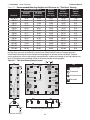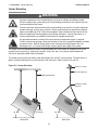
1
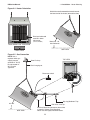
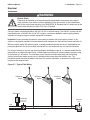
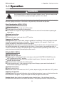
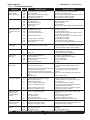
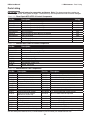
Detroit Radiant Products Co.
DR Series Manual
Installation, Operation
Maintenance and Parts
!
All persons involved with the installation, operation and maintenance of the heater system must read and
understand the information in this manual.
!
WARNING
Improper installation, adjustment, alteration, service or maintenance can cause
property damage, injury or death. Read and understand the installation, operating and
maintenance instructions thoroughly before installing or servicing this equipment.
Only trained, qualified gas installation and service personnel may install or service
this equipment. Failure to comply could result in personal injury, asphyxiation, death,
fire and/or property damage.
In locations used for the storage of combustible materials, signs must be posted to
specify the maximum permissible stacking height to maintain the required clearances
from the heater to the combustibles. Signs must either be posted adjacent to the
heater thermostats or in the absence of such thermostats, in a conspicuous location.
Not for residential use!
This heater is not approved in any residential application. This includes (but is not limited to) the home,
living quarters, attached garages, etc. Installation in residential indoor spaces may result in property
damage, asphyxiation, serious injury or death.
For Your Safety
If you smell gas:
• Do not try to light any appliance. • Immediately call your gas supplier from a neighbor’s phone.
• Do not touch any electrical switch.
• Follow the gas supplier’s instructions.
• Do not use any phone in your building. • If you cannot reach your gas supplier, call the fire department.
Keep these instructions for future reference.
LIODR-Rev. 25911
Print: 5M-10/12_r2-10/13(CDS)
Replaces: LIODR-5M-9/11(CDS)
DR Series Manual
Contents
1.0 Safety . . . . . . . . . . . . . . . . . . . . . . . . . . . . . . . . . . . . . . . . . . . . . . . . . . . . . . . . . . . . . . . . . . . .
Safety Symbols . . . . . . . . . . . . . . . . . . . . . . . . . . . . . . . . . . . . . . . . . . . . . . . . . . . . . . .
Applications . . . . . . . . . . . . . . . . . . . . . . . . . . . . . . . . . . . . . . . . . . . . . . . . . . . . . . . . . .
Clearance to Combustibles . . . . . . . . . . . . . . . . . . . . . . . . . . . . . . . . . . . . . . . . . . . . . .
Gas Connection . . . . . . . . . . . . . . . . . . . . . . . . . . . . . . . . . . . . . . . . . . . . . . . . . . . . . . .
Standards, Certifications and Government Regulations . . . . . . . . . . . . . . . . . . . . . . . .
Safety Signs and Labels . . . . . . . . . . . . . . . . . . . . . . . . . . . . . . . . . . . . . . . . . . . . . . . . .
3
3
3
4
6
6
8
2.0 Installation . . . . . . . . . . . . . . . . . . . . . . . . . . . . . . . . . . . . . . . . . . . . . . . . . . . . . . . . . . . . . . . 9
Design . . . . . . . . . . . . . . . . . . . . . . . . . . . . . . . . . . . . . . . . . . . . . . . . . . . . . . . . . . . . . 9
Heater Placement . . . . . . . . . . . . . . . . . . . . . . . . . . . . . . . . . . . . . . . . . . . . . . . . . . . . . 10
Total Area Heating . . . . . . . . . . . . . . . . . . . . . . . . . . . . . . . . . . . . . . . . . . . . . . . . . . 10
Spot Heating . . . . . . . . . . . . . . . . . . . . . . . . . . . . . . . . . . . . . . . . . . . . . . . . . . . . . . 11
Heater Mounting . . . . . . . . . . . . . . . . . . . . . . . . . . . . . . . . . . . . . . . . . . . . . . . . . . . . . . 12
Ventilation . . . . . . . . . . . . . . . . . . . . . . . . . . . . . . . . . . . . . . . . . . . . . . . . . . . . . . . . . . . 14
Gas Supply . . . . . . . . . . . . . . . . . . . . . . . . . . . . . . . . . . . . . . . . . . . . . . . . . . . . . . . . . . 15
Electrical . . . . . . . . . . . . . . . . . . . . . . . . . . . . . . . . . . . . . . . . . . . . . . . . . . . . . . . . . . . . . 17
3.0 Operation . . . . . . . . . . . . . . . . . . . . . . . . . . . . . . . . . . . . . . . . . . . . . . . . . . . . . . . . . . . . . . . . . 19
4.0 Maintenance . . . . . . . . . . . . . . . . . . . . . . . . . . . . . . . . . . . . . . . . . . . . . . . . . . . . . . . . . . . . . . 20
Troubleshooting Guide . . . . . . . . . . . . . . . . . . . . . . . . . . . . . . . . . . . . . . . . . . . . . . . . . 21
Heater Assembly Components . . . . . . . . . . . . . . . . . . . . . . . . . . . . . . . . . . . . . . . . . . . 22
Parts Listing . . . . . . . . . . . . . . . . . . . . . . . . . . . . . . . . . . . . . . . . . . . . . . . . . . . . . . . . . . 23
5.0 Limited Warranty . . . . . . . . . . . . . . . . . . . . . . . . . . . . . . . . . . . . . . . . . . . . . . . . . . . . . . . . . . 24
2
DR Series Manual
1.0 Safety • Safety Symbols • Applications
1.0 Safety
!
!
WARNING
Improper installation, adjustment, alteration, service or maintenance can cause
property damage, serious injury or death. Read and understand the installation,
operating and maintenance instructions thoroughly before installing or servicing this
equipment. Only trained, qualified gas installation and service personnel may install or
service this equipment.
Safety Symbols
Safety is the most important consideration during installation, operation and maintenance of the infrared
heater. You will see the following symbols and signal words when there is a hazard related to safety or
property damage.
!
!
WARNING
Warning indicates a potentially hazardous situation
which, if not avoided, could result in death or injury.
CAUTION
Caution indicates a potentially hazardous situation
which, if not avoided, could result in minor or
moderate injury.
NOTICE
Notice indicates a potentially hazardous situation
which, if not avoided, could result in property
damage.
Applications
This is not an explosion proof heater. Consult your local fire marshall, insurance carrier and other
authorities for approval of the proposed installation.
Commercial / Industrial
Infrared heaters are designed and certified !for use in industrial and commercial buildings such as
warehouses, manufacturing plants, aircraft hangars and vehicle maintenance shops. For maximum safety,
the building must be evaluated for potential hazards before installing the heater system. A critical safety
factor to consider before installation is the clearance to combustibles.
Residential
This heater is NOT approved for use in any residential application. This includes, but not limited to,
attached garages, living quarters, solariums, etc. Consult the local fire marshal and/or insurance provider
if unsure of your application.
!
WARNING
Not For Residential Use.
Installation of an infrared heater system in residential indoor spaces, RV’s,
mobile homes, etc. may result in property damage, asphyxiation, fire, serious
injury or death.
3
DR Series Manual
1.0 Safety • Clearance to Combustibles
Clearance to Combustibles
!
WARNING
Improperly connected gas lines may result in serious injury or
death, explosion, poisonous fumes, toxic gases, asphyxiation.
Connect gas lines in accordance to national, state, provincial
and local codes.
Placement of explosive objects, flammable objects, liquids and vapors close to the heater may result in
explosion, fire, property damage, serious injury or death. Do not store, or use, explosive objects, liquids
and vapor in the vicinity of the heater.
Failure to comply with the published clearances to combustibles could result in personal injury, death
and/or property damage.
!
CAUTION
Signs shall be posted specifying the maximum permissible stacking height in order to
maintain clearances to combustibles.
Hazards Include:
For maximum safety the building must be evaluated for hazards before installing the heater system.
Examples include, but are not limited to:
•
•
•
•
•
•
•
Gas and electrical lines
Combustible and explosive materials
Chemical storage areas
Areas of high chemical fume concentrations
Provisions for accessibility to the heater
Adequate clearances around air openings
Combustion and ventilating air supply
•
•
•
•
•
•
•
Vehicle parking areas
Vehicles with lifts or cranes
Storage areas with stacked materials
Lights
Sprinkler heads
Overhead doors and tracks
Dirty, contaminated environment
A critical safety factor to consider before installation is the clearances to combustibles. Clearance to
combustibles is defined as the minimum distance you must have between the infrared surface, or
reflector, and the combustible item. Considerations must also be made for moving objects around the
infrared heater. The following is a partial list of items to maintain clearances from:
Combustible Items Include: Moving Objects Include:
•
•
•
•
•
•
•
•
•
•
Wood
Paper
Fabric
Chemicals
Wall or roof insulation
Overhead doors
Vehicles on lifts
Cranes
Hoists
Car wash equipment
When installing the infrared heater system, the minimum clearances to combustibles must be maintained.
These distances are shown in Chart 1.1 and on the heater. If you are unsure of the potential hazards,
consult your local fire marshall, fire insurance carrier or other qualified authorities on the installation of gas
fired infrared heaters for approval of the proposed installation.
4
DR Series Manual
1.0 Safety • Clearance to Combustibles
Chart 1.1 • Clearance to Combustibles in Inches (see Figure 1.1)
Model No.
Sides
Back
Top
Below/Front
DR 30 (S)
30
18
28
72
DR 45
30
18
28
72
DR 50
30
18
34
72
DR 55
32
18
40
72*
DR 60
32
18
40
72*
DR 75
48
30
42
98
DR 80
48
30
42
98
DR 85
48
30
42
98
DR 90
48
30
42
98
DR 95
48
30
52
120
DR 100
48
30
52
120
DR 130
48
30
52
120
DR 160
50
32
60
132
* This clearance is 80 in. when the heater is fitted with a parabolic reflector.
NOTE: If the heater is mounted beneath a non-combustible surface, a 24 in. minimum top clearance must
be maintained from the top of the heater to prevent overheating the controls.
Figure 1.1 • Clearance to Combustibles
Top
Back
Manifold or
Control End
Side
Side
Front
20° - 35°
Mount Heater Level
- Side to Side Below
FRONT VIEW
SIDE VIEW
5
1.0 Safety • Gas Connection • Standards, Certifications and Government Regulations
DR Series Manual
Gas Connection
!
WARNING
An approved connector, suitable for the environment of equipment usage, is required.
Visible or excessive swaying, flexing and vibration of the gas connections must be avoided
to prevent failure. Neither the gas pipe nor the connector shall be placed in the ‘flue
discharge area’. In no case shall the gas supply support the weight of the heater.
To ensure your safety, and comply with the terms of the warranty, all units must be installed in accordance
with these instructions.
Standards, Certifications and Government Regulations
Installation of this infrared heater must comply with all applicable local, state and national specifications,
regulations and building codes. Contact the local building inspector and/or fire marshall for guidance.
In the absence of local codes, the installation must conform to the latest edition of:
United States: National Fuel Gas Code, ANSI Z223.1 (NFPA 54).
Canada: CAN/CGA B149.1 and .2, Canadian Electrical Code C22.1
Chart 1.2 • Standards and Code Installation Guidelines • Building Aspect
Building
Aspect
Electrical
Codes and Guidelines
The heater must be electrically grounded in accordance with the following codes:
United States: Refer to National Electrical Code®, ANSI/NFPA 70 (latest edition). Wiring must conform to the latest edition of National Electrical Code®, local ordinances, and any special diagrams furnished.
Canada: Refer to Canadian Electrical Code CSA C22.1 Part 1 (latest edition).
Venting
The space being heated by unvented heaters must meet ventilation requirements.
6
DR Series Manual
1.0 Safety • Standards, Certifications and Government Regulations
Chart 1.3 • Standards and Code Installation Guidelines • Building Type
Building
Type
Codes and Guidelines
Public
Garages
Installation of this infrared heater in public garages must conform to the following codes:
United States: Standard for Parking Structures NFPA 88A (latest edition) or the Code for Motor Fuel Dispensing Facilities and Repair Garages NFPA 30A (latest edition).
Canada: R
efer to CAN/CGA B149.1 and B149.2: Installation Codes for Gas Burning Appliances.
Guidelines:
• Heaters must not be installed less than 8 ft. (2.4 m) above the floor. Minimum clearances to combustibles must be maintained from vehicles parked below the
heater.
Aircraft
Hangars
• When installed over hoists, minimum clearances to combustibles must be maintained from the upper most point of objects on the hoist.
Installation of this infrared heater in aircraft hangars must be in accordance with the
following codes:
United States: Refer to Standard for Aircraft Hangars, ANSI/NFPA 409 (latest edition).
In Canada:Refer to Standard CAN/CGA B149.1 and B149.2.
Guidelines:
• In aircraft storage and servicing areas, heaters shall be installed at least 10 ft. (3 m) from above the upper surface of wings or of the engine enclosures of the highest aircraft that may be housed in the hangar. The measurement shall be made from the wing or engine enclosure, whichever is higher from the floor, to the bottom of the heater.
• In areas adjoining the aircraft storage area (e.g., shops, offices) the bottom of heaters shall be installed no less than 8 ft. (2.4 m) above the floor.
• Suspended or elevated heaters shall be located in spaces where they shall not be subject to damage by aircraft, cranes, movable scaffolding or other objects.
Provisions shall be made to assure accessibility to suspended infrared heaters for
recurrent maintenance purposes.
Detroit Radiant Products units comply or are certified by one or more of the following
organizations or standards:
• CSA Design Certified (CSA 2.35).
• American National Standards (ANSI Z83.19).
• Underwriters Laboratory (UL).
• Certification of Europe (CE).
• Infrared Heater Safety Council. (IRSC).
7
DR Series Manual
1.0 Safety • Safety Signs and Labels
Safety Signs and Labels
It is important to provide warnings to alert individuals to potential hazards and safety actions. ANSI Z83.19
and the National Fuel Gas Code require you to post a sign “specifying the maximum permissible stacking
height to maintain the required clearances from the heater to the combustibles” near the heater’s
thermostat or in absence of such thermostats in a conspicuous location. Signs should state the hazards
for the particular application and be legible to the building occupants. Consult the factory or a factory
representative for additional information on signage compliance.
Safety warning labels must be maintained on the
infrared heater. Illustrations of the safety labels,
and their locations, are pictured below.
®
RE-VERBER-RAY INFRA-RED RADIANT HEATER
FOR OUTDOOR USE AND INDOOR (Non-Residential) INSTALLATION ONLY.
High - Intensity Infrared Heater
Class IIIA Permanent Label
MODEL NO.
DR60-NFS-2 120
Volts AC:
Back View
120V - 60Hz
AMPS - Starting:
0.1
AMPS - Running:
0.1
Heater Type:
INPUT BTU/H
VERSION
05/97
60,000
LE
Manifold Pressure:
6.0 in.
MP
W.C.P.
Maximum Inlet Pressure:
SA
14 in.
W.C.P.
Natural Gas
Heater Type
C1
Minimum Mounting Angle:
20 DEGREES
Minimum Inlet Pressure:
7.0 in.
FOR USE WITH
Maximum Mounting Angle:
W.C.P.
35 DEGREES
C1
DESIGN COMPLIES WITH:
Serial No. 08 07 DRPC 123456 0001
ANSI Z83.20-2001-GAS FIRED LOW INTENSITY INFRA-RED HTR.
DETROIT RADIANT PRODUCTS COMPANY
21400 HOOVER ROAD - WARREN, MI
(586) 756-0950
www.drp-co.com
Rating Plate
Bottom View
®
RE-VERBER-RAY INFRA-RED RADIANT HEATER
FOR OUTDOOR USE AND INDOOR (Non-Residential) INSTALLATION ONLY.
High - Intensity Infrared Heater
Class IIIA Permanent Label
MODEL NO.
INPUT BTU/H
DR60-NFS-2 120
60,000
Volts AC:
VERSION
05/97
Manifold Pressure:
120V - 60Hz
6.0 in.
AMPS - Starting:
W.C.P.
Maximum Inlet Pressure:
0.1
14 in.
AMPS - Running:
W.C.P.
Minimum Inlet Pressure:
0.1
7.0 in.
W.C.P.
FOR USE WITH
Natural Gas
Heater Type
C1
Minimum Mounting Angle:
20 DEGREES
Maximum Mounting Angle:
35 DEGREES
Heater Type:
C1
DESIGN COMPLIES WITH:
ANSI Z83.20-2001-GAS FIRED LOW INTENSITY INFRA-RED HTR.
Serial No. 08 07 DRPC 123456 0001
DETROIT RADIANT PRODUCTS COMPANY
21400 HOOVER ROAD - WARREN, MI
(586) 756-0950
www.drp-co.com
F/N: LL01 - Clearance
Safety Tag
(Affix adjacent to
heater’s thermostat)
F/N: LLDR002
8
F/N: LLDCL002
Clearance to Combustibles Label
DR Series Manual
2.0 Installation • Design
2.0 Installation
WARNING
!
Read and understand, the installation, operating and maintenance instructions thoroughly
before installing or servicing this equipment.
Only trained, qualified gas installation and service personnel may install or service this
equipment.
!
CAUTION
This heater cannot be used in a building with an uninsulated roof or condensation problems can occur.
Design
To ensure a safe, properly designed heating system, a layout should be developed for the correct
placement of the infrared heater(s). Aside from safety factors such as clearance to combustibles (see
Chart 1.1 on page 5), you should take also into consideration the environment (e.g., cold/drafty, average,
protected), heat coverage (sq. ft.) needed, heater centers, the distance behind a person or work station(s)
and exhaust path. Also, the effective infrared surface temperature of a person or object may be
diminished with wind above 5 mph. Wind barrier(s) may be required. Most importantly, clearance to
combustibles must always be maintained! Refer to hazards on page 4.
This installation manual, along with national, state, provincial and local codes, address these issues. It is
critical that you read, understand and follow all guidelines and instructions. Always inspect and evaluate
the mounting conditions, space for exhaust, gas supply and wiring.
Perimeter mounting of infrared heaters provides the most effective distribution of heat. The recommended
spacing between the heaters is shown in Chart 2.1. Add additional heaters in the center of the space
when heaters are spaced farther than the recommended distance (see Figure 2.1 ).
When heated, materials high in hydrocarbons (solvents, paint thinner, mineral spirits, formaldehydes, etc.)
can evaporate. This may result in odors or fumes being emitted into the environment. To correct this
problem, clean the area and/or introduce additional ventilation. Heaters installed and serviced in
accordance with the installation manual do not emit foul odors into the environment.
IMPORTANT: Fire sprinkler heads must be located at an appropriate distance from the heater. This
distance may exceed the published clearance to combustibles. Certain applications will require the use
of high temperature sprinkler heads or relocation of the heaters.
Sprinkler systems containing propylene glycol or other flammable substances are not to be used in
conjunction with this heater without careful consideration for and avoidance of potential fire or explosion
hazards. For further information consult NFPA 13. Always observe applicable state and local codes.
9
DR Series Manual
2.0 Installation • Heater Placement
Chart 2.1 • Recommended Mounting Heights and Distances for “Total Area” Heating
Mounting Heights Dim. A
Model No.
30º Angle
Standard
Reflector (ft.)
30º Angle
Parabolic
Reflector (ft.)
Distance
Between
Heaters
Dim. B (ft.)
Distance
Between
Heater Rows
Dim. C (ft.)
Distance
Between
Heater
and Wall (ft.)
DR 30(S)
12-14
12-15
8-24
15-40
4-8
DR 45
12-14
16-19
12-36
15-55
6-12
DR 50
12-14
17-20
12-36
15-55
6-12
DR 55
13-15
18-21
12-36
15-55
6-12
DR 60
14-16
18-21
12-36
15-55
6-12
DR 75
15-17
19-22
16-48
20-70
6-12
DR 80
15-17
19-22
16-48
20-70
6-12
DR 85
16-18
21-25
16-48
20-70
6-12
DR 90
16-18
21-25
16-48
20-70
6-12
DR 95
17-20
21-25
16-48
20-70
6-12
DR 100
17-20
23-27
16-48
20-70
6-12
DR 130
21-24
26-32
20-60
25-85
8-14
DR 160
24-28
29-35
24-65
30-100
8-14
Factory recommended mounting heights are listed as a guideline. If infrared heaters are mounted too low or
too high, they may result in discomfort or lack of heat. Detroit Radiant Products Company generally
recommends observing the recommended mounting heights to optimize comfort conditions. However,
certain applications such as spot heating, freeze protection, outdoor patio heating or very high ceilings may
result in the heaters being mounted outside of the recommended mounting heights.
Figure 2.1 • Total Area Heating Sample Layout
B
Key
Infrared heater
B
Thermostat
C
Air intake louver
Exhauster
A
A
Perimeter mounting
Perimeter and center row mounting
10
DR Series Manual
2.0 Installation • Heater Placement
Centers for Full Coverage
(Spot & Area) Htg. Only
12’
DR-30
Cold/Drafty
10’ x 10’
100
9’
30,000
BTU/h
Average
12’ x 12’
144
10’
12’
Protected/Insul.
14’ x 14’
196
DR-45
Cold/Drafty
12’ x 12’
144
10’
12’
45,000
BTU/h
Average
14’ x 14’
196
Protected/Insul.
16’ x 16’
256
DR-60
Cold/Drafty
16’ x 16’
256
60,000
BTU/h
Average
18’ x 18’
324
Protected/Insul.
20’ x 20’
400
DR-75
Cold/Drafty
18’ x 18’
324
75,000
BTU/h
Average
22’ x 22’
484
Protected/Insul.
26’ x 26’
676
DR-90
Cold/Drafty
20’ x 20’
400
90,000
BTU/h
Average
24’ x 24’
576
Protected/Insul.
28’ x 28’
784
DR-95
Cold/Drafty
24’ x 24’
576
18’
95,000
BTU/h
Average
28‘ x 28’
784
18’
Protected/Insul.
32’ x 32’
1024
DR-100
Cold/Drafty
24’ x 24’
576
18’
100,000
BTU/h
Average
28‘ x 28’
784
18’
Protected/Insul.
32’ x 32’
1024
DR-130
Cold/Drafty
26’ x 26’
676
18’
130,000
BTU/h
Average
30’ x 30’
900
18’
12’
28’
Protected/Insul.
35’ x 35’
1225
20’
22’
13’
32’
DR-160
Cold/Drafty
28’ x 28’
784
20’
22’
12’
28’
160,000
BTU/h
Average
35’ x 35’
1225
16’
32’
Protected/Insul.
40’ x 40’
1600
20’
35’
Recommended
Mounting Height
(Dim. A)
Approx. Coverage
(sq. ft.)
5’
Approx. Area Covered
10’
Type of Area
(Surroundings)
4’
Model & Input
Distance Behind Person
or Work Station (Dim. B)
Chart 2.2 • Recommended Mounting Heights and Distances for “Spot” Heating
10’ 12’ 14’ 16’ 18’ 20’ 22’ 24’ 26’ 28’ 30’
12’
12’
14’
14’
5’
12’
6’
14’
16’
7’
16’
6’
16’
16’
7’
18’
8’
20’
7’
18’
14’
14’
12’
6’
14’
14’
16’
14’
18’
16’
16’
18’
18’
16’
20’
18’
18’
20’
20’
A
11
24’
9’
20’
10’
24’
11’
26’
24’
20’
11’
26’
20’
12’
26’
10’
24’
20’
11’
26’
20’
12’
30’
11’
26’
20’
26’
28’
B
22’
10’
24’
Figure 2.2 • Spot Heater Heights
8’
9’
30’
DR Series Manual
2.0 Installation • Heater Mounting
Heater Mounting
!
WARNING
Improper suspension of the infrared heater may result in collapse and being crushed.
Always suspend from a permanent part of the building structure that can support the total
force and weight of the heater.
Failure to maintain minimum clearance to combustibles may result in fire and/or explosion,
property damage, serious injury or death. Always maintain minimum clearances and post
signs or provided tags (F/N: LL01) where needed. Signs should state the hazards for the
particular application and be legible to the building occupants. Consult the factory or a
factory representative for additional information on signage compliance.
An approved connector, suitable for the environment of equipment usage, is required.
Visible or excessive swaying, flexing and vibration of the gas connections must be avoided
to prevent failure. Neither the gas pipe nor the connector shall be placed in the ‘flue
discharge area’. In no case shall the gas supply support the weight of the heater.
The heater can be suspended with chains or rigid threaded rod. Local codes, or conditions that would
cause the unit to move (e.g., wind drafts, blowers, crane rails, etc.), may require rigid threaded rod.
Consult all applicable codes before installation.
The heater must be level from side to side and between 20° and 35° from horizontal. The pilot burner or
ignitor, manifold and controls must be located on the lower end. Refer to figures 2.3 and 2.4.
Figure 2.3 • Heater Mounting
Steel “C” clamp
Chain hanging set
Rigid threaded rod
Closed “S” hook
(typical)
Control
End Down
20˚ - 35˚
Control
End Down
20˚ - 35˚
SIDE VIEW
SIDE VIEW
12
DR Series Manual
2.0 Installation • Heater Mounting
Figure 2.4 • Heater Orientation
Manifold control box must be located towards
the lower end of the heater (towards the floor).
Pilot/spark electrode
must be in lower
right corner.
(excludes DR30S)
Mount Heater Level - Side to Side
Mount 20˚ - 35˚
from horizontal
SIDE VIEW
FRONT VIEW
Figure 2.5 • Gas Connection
NOTE: Use a
regulator when gas
supply pressure
exceeds 14” W.C.P.
Do not exceed 14”
W.C.P to the
appliance.
TOP VIEW
Steel C-clamp
Chain hanging set
Disconnect switch
Drip Leg/Sediment Trap
20˚ - 35˚
Ball Valve / Inlet Tap
SIDE VIEW
Stainless Steel Gas Connector, formed into
a smooth C-Shape (Field Supplied)
Not for use with rigidly mounted heaters.
13
DR Series Manual
2.0 Installation • Ventilation
Ventilation
!
WARNING
Insufficient ventilation may result in health problems, carbon monoxide
poisoning or death. Vent enclosed spaces and buildings according to
national, state, provincial and local codes.
Improper venting may result in asphyxiation, fire, explosion, injury or death.
It is required that the levels where heaters are mounted be properly ventilated to supply combustion
air to the heaters and to sufficiently dilute the products of combustion. It is also required that the flue
discharge area is kept clear of gas piping and electrical wiring (see Figure 2.6).
This infrared heater must be vented in accordance with national, state, provincial and local codes and the
guidelines in this manual. In the United Sates refer to the latest edition of ANSI Z223.1 (NFPA 54) and in
Canada refer to the latest edition of the CAN/CGA B149.2 Standard.
Figure 2.6 • Hot Flue Discharge
Flue Discharge Area
Important! Do not
install gas piping or
electrical wiring above
the flue discharge
area!
Manifold/Control
End Down
20˚ - 35˚
SIDE VIEW
Provisions must also be made to provide sufficient fresh air intake area and exhaust air outlet area. For
proper ventilation, a positive air displacement of 4 cfm/1,000 BTU/h of gas consumed must be provided.
Where insufficient air movement exists, induced air displacement is required. A balanced system is
essential to avoid negative building pressure which causes excessive infiltration, unfavorable drafts and
affects combustion efficiency.
Air displacement may be accomplished by either natural or mechanical means. Mechanical exhausters
are preferred and typically mounted at high points on the roof where stagnant air accumulates inside
the building. For a flat roof, considerations of prevailing winds, high and low pressure areas, and
distribution of air movement must be taken into consideration when locating exhausters.
Best air distribution is accomplished by using a number of small exhausters versus one large exhauster.
Provide a minimum of one square inch of inlet area per 1,000 BTU/h for combustion air supply. Inlet
opening in the building should be well distributed (see Figure 2.1) high in the sidewalls and should direct
incoming air upward to dilute products of combustion while preventing drafts at lower levels. Inlets are
typically 1 to 3 sq. ft.
Local codes may require that mechanical exhaust systems be interlocked with heaters to enable both to
function simultaneously (see page 17, Figure 2.7) or allow control of exhausters with a ceiling mounted
humidistat.
14
DR Series Manual
2.0 Installation • Gas Supply
Gas Supply
WARNING
!
Improperly connected gas lines may result in fire, explosion,
poisonous fumes, toxic gases, asphyxiation or death.
Connect gas lines in accordance to national, state, provincial
and local codes.
The gas supply to the infrared heater must be connected and tested in accordance with national, state,
provincial and local codes along with the guidelines in the Detroit Radiant DR Series manual. In the
United States refer to the latest edition of the ANSI Z223.1 (NFPA 54) Standard and in Canada refer to the
latest edition of the CAN/CGA B149.2 Standard.
Important! Before connecting the gas supply to the infrared heater(s):
• Check that the gas piping and service has the capacity to handle the load of all heaters being installed, as well as any other gas appliances being connected to the supply line.
• Check that the main gas supply line is of proper diameter to supply the required fuel pressures.
• If utilizing used pipe, verify that its condition is clean and comparable to a new pipe. Test all gas supply lines in accordance with local codes.
• Test and confirm that inlet pressures are correct. Refer to the rating plate for required minimum and maximum pressures (see Chart 2.3). The gas supply pipe must be of sufficient size to provide the required capacity and inlet pressure to the heater (if necessary, consult the local
gas company).
Chart 2.3 • Manifold Pressure
Type of Gas
Required Manifold
Pressure
Minimum Inlet
Pressure
Maximum Inlet
Pressure
Natural
6.0 Inches W.C.
7.0 Inches W.C.
14.0 Inches W.C.
Liquefied Petroleum
10.0 Inches W.C.
11.0 Inches W.C.
14.0 Inches W.C.
!
Note: Check manifold pressure at the tap located either at the outlet of the gas valve or on the gas
manifold pipe. Readings will be above atmospheric pressure during operation.
Pressure Equivalents: 1 inch W.C. equals .058 oz/sq. in. equals 2.49 Mbar.
To connect the gas:
!
WARNING
Failure to install, operate or service this appliance in the approved manner may result in
property damage, injury or death.
This heater must be installed and serviced by trained gas installation and service personnel only.
The installation of this heater must conform with local building codes or, in the absence of such codes, the
National Fuel Code (NFPA 54).
15
DR Series Manual
2.0 Installation • Gas Supply
!
WARNING
An approved connector, suitable for the environment of equipment usage, is required.
Visible or excessive swaying, flexing and vibration of the gas connections must be avoided
to prevent failure. Neither the gas pipe nor the connector shall be placed in the ‘flue
discharge area’. In no case shall the gas supply support the weight of the heater.
The gas outlet must be in the same room as the appliance and accessible. It may not be concealed within
or run through any wall, floor or partition.
1 Install a sediment trap / drip leg if condensation may occur at any point of the gas supply line. This will decrease the possibly of loose scale or dirt in the supply line entering the heater’s control system and causing a malfunction. Note: High pressure gas above 14 in. W.C.P. (water column pressure) requires a high pressure regulator and ball valve (field supplied).
2 Form the stainless steel flexible connector (field supplied) into a smooth C-shape allowing 12 in. between the flexible connector’s end nuts. Figure 2.5 on page 13. NOTE: Not for use on rigidly mounted heaters.
3 Attach the ball valve (field supplied) to the gas supply pipe. Apply pipe compound to NPT adapter threads to seal the joint. Use only a pipe compound resistant to liquid petroleum.
NOTE: Provide a 1/8 in. NPT plugged tapping accessible for test gauge connection immediately upstream of gas connection to the heater (provided on ball valve, when supplied).
!!
CAUTION
The fittings (nuts) on the flexible connector must be connected to an adapter. They may not be
directly connected to the gas supply pipe.
4 Attach the flexible connector to the adapter and gas inlet. Seal the joints.
Note: Excessive torque on the manifold may misalign the orifice. Always use two wrenches to tighten mating pipe connections.
!
WARNING
Testing for gas leaks with an open flame or other sources of ignition may lead to a fire
or explosion and cause serious injury or death. Test in accordance with NFPA or local
codes.
5 Final assembly must be tested for gas leaks according to NFPA or local codes.
!
CAUTION
In high moisture or corrosive environments, use gas supply lines and connectors suitable for the
environment. Periodically inspect for signs of failure or leakage.
16
DR Series Manual
2.0 Installation • Electrical
Electrical
!
WARNING
Electric Shock
Field wiring to the heater must be connected and grounded in accordance with national,
state, provincial, local codes and to the guidelines in the this manual. In the United States
refer to the most current revisions to the ANSI/NFPA 70 Standard and in Canada refer to the
most current revisions the CSA C22.1 Part I Standard.
Control systems are initiated by either 120 VAC, 24 VAC or millivolt energy. The 120 VAC systems can be
used directly from a 120 VAC line. On 24 VAC systems, transformers must be used to supply power of
sufficient VA rating for single or multiple connected installations.
Important! Proper grounding and polarity are essential for heaters with spark ignition controls. If the
system is not properly grounded, it cannot determine the presence of a flame and will lockout and shut off.
Millivolt systems require NO external power, as energy needed to operate the valve is developed by the
power-pile generator. Do not use multiple connections, as one thermostat may only control one heater.
For wiring of controls on the unit see the wiring diagram included on page 18. It is recommended that the
thermostat be installed on the hot side of a fused supply line and have a sufficient ampere capacity rating
for the heater(s) it will control. The ventilation system may be controlled separately from the heating
system (consult local codes) by the use of a humidistat that closes when the humidity rises. The
humidistat control should be installed at roof level. For summer ventilation, a simple on/off switch can be
installed at the occupant level.
Figure 2.7 • Typical Field Wiring
DR Series
Heater
DR Series
Heater
DR Series
Heater
Thermostat
Transformer
Exhaust
Fan
(required on
24V heaters)
Hot
Neutral
17
DR Series Manual
2.0 Installation • Wiring Diagrams
Wiring Diagrams
Figure 2.8 • NMV-2/PMV-2 • 750 Schematic
• Millivolt Control
N/PFS-2 24VAC
Figure 2.9 • NFS-2/PFS-2 (24V) • 24 V Schematic
• Direct Spark
Ignition
• VA Draw: 12
BL
O
ELECTRODE
ASSEMBLY
W
(24VAC)
W
• Amps: .48
SENSE
• Potted Circuit
Board
GROUND
NEUTRAL
THERMOSTAT
VALVE
W
GAS VALVE
24VAC DSI MODULE
G
BK
HIGH
VOLTAGE
G
G
(COMMON)
Figure 2.10 • NFS-2/PFS-2 (120V) • 120 V Schematic
•Direct Spark Ignition
•VA Draw: 12
BK
O
ELECTRODE
ASSEMBLY
BK
W
•Amps: .10
•Potted Circuit
Board
L1
SENSE
NEUTRAL
LLWDR002 REV. 1
W
THERMOSTAT
NEUTRAL
VALVE
GROUND
W
GAS VALVE
BK
HIGH
VOLTAGE
120VAC DSI MODULE
G
BK
G
G
W
18
L2
DR Series Manual
3.0 Operation • Lighting Instructions
3.0 Operation
!
WARNING
Do not attempt to ignite a direct spark ignition heater by hand. Failure to comply could
result in personal injury, property damage, explosion, fire or death.
Upon satisfactory completion of the electrical supply and purging of the gas supply line to the heater(s),
follow the lighting instructions on the heater’s rating label to put the heater into operation.
Direct Spark Ignition (NFS-2 / PFS-2)
Lighting Instructions
1Rotate the heater’s valve knob to the “ON” position.
2Close electrical circuit (typically the thermostat).
3If the heater fails to light, turn off gas, open electrical circuit and wait 5 minutes before repeating the
above steps.
Shutdown Instructions
1Open electrical circuit.
2Rotate the heater’s valve knob to the “OFF” position.
Sequence of Operation
Starting Circuit: Upon a call for heat, voltage is applied to L1 and Neutral. After a pre-purge, the spark
electrode is energized and the gas valve opens. The trial for ignition is 15 seconds. If flame is not
sensed, the heater will attempt two more times to reignite.
Running Circuit: After ignition, the sensing electrode monitors the burner flame. If sense of flame is lost,
the control immediately acts to reignite the gas-air mixture. If flame sense is not established within 15
seconds, the heater will attempt two additional ignition sequences before proceeding to hard lockout. The
control can be reset by briefly interrupting the power source.
Millivolt (NMV-2 / PMV-2)
Lighting Instructions
1Purge main gas supply line.
2Slightly depress and rotate the heater’s manual gas valve knob COUNTERCLOCKWISE from the
“OFF” position to the “PILOT” position.
3Fully depress the manual gas valve knob and light the pilot burner.
Continue to depress for 30
seconds and then release.
4Rotate the heater’s valve knob to the “ON” position.
5Close the control circuit. If the heater fails to light, turn off the gas, open control circuit and wait 5
minutes before repeating the above steps.
Shutdown Instructions
1Open the control circuit.
2Rotate the heater’s valve knob to the “PILOT” position, depress slightly and rotate to the “OFF” position.
Sequence of Operation
Starting Circuit: After manually lighting the pilot (see lighting instructions), upon a call for heat, the main
burner solenoid is energized. The gas valve opens and the pilot lights the main burner.
Running Circuit: After ignition, the powerpile monitors the pilot flame. If the pilot flame is lost, the
powerpile cools and closes the valve within 180 seconds. See lighting instructions to relight the heater.
19
DR Series Manual
4.0 Maintenance • Maintenance Checks
4.0 Maintenance
It is recommended that the following become a standard yearly procedure to obtain maximum operating
efficiency and trouble free operation.
During long periods of non-usage, remove or cover heater with a polyethylene bag and shut off gas
supply. If further service to the heater is desired, contact your representative or the factory.
Main Burner
1Gently use an air hose to blow any
!
accumulated dust and/or dirt off the heater.
Air hose pressure must not exceed 30 psig.
Use protective glasses when cleaning
the heater.
2Gently pass the air hose over the entire
WARNING
exposed area of the ceramic. A distance of
2’ to 4’ from the unit is recommended.
NOTE: Blowing out the gasket material will
permanently damage the rayhead.
Disconnect power to heater before
servicing.
3Gently place the air hose outlet into each
Do not operate unit if repairs are
necessary. Do not operate unit
showing any signs of burner
malfunction. Call a professional for
assistance.
venturi tube and allow the air to flow for
approximately one minute.
4See troubleshooting chart (page 21) if there
are any signs of burner malfunction. Replace
if necessary.
!
Pilot Burner
CAUTION
Avoid Equipment Failure.
1Remove pilot access door.
Do not blow out heating elements
with high pressure air.
2Use an air hose and gently blow the pilot
burner free of dust or debris.
Gas Supply
1 Periodically inspect the gas supply for signs
of corrosion or failure. Replace if necessary.
20
DR Series Manual
4.0 Maintenance • Troubleshooting
Chart 4.1 Troubleshooting Guide
Symptom
Code
Possible Cause
Corrective Action
Burning of gas-air
mixture inside
plenum (flashback).
A, B
A, B
A, B
A, B
A, B
• Heater mounted at incorrect angle.
• Excessive drafts.
• Gas leaking or blocked orifice/venturi.
• Separation of ceramic grids.
• Ceramic grids cracked.
• Mounting angle 20°-35° from horizontal.
• Relocate or shield from draft.
• Do not operate. Check with leak detector solution.
• Do not operate. Replace rayhead.
• Do not operate. Replace rayhead.
Delayed ignition.
A
A, B
A, B
A, B
A, B
• Electrode out of specification.
• Low gas pressure.
• Partially blocked orifice.
• Improper orifice size.
• Incorrect gas.
• See Figure 4.3.
• See Gas Supply section.
• Clean or replace.
• Consult dealer.
• Do not operate. See nameplate. Correct immediately.
Low ceramic surface
temperature, excessive rollout or soot on
rods.
A, B
A, B
A, B
A, B
• Dirty or plugged rayhead ceramics.
• Partially blocked orifice.
• Low inlet gas pressure.
• Low manifold gas pressure.
A, B
• High manifold pressure.
A, B
A, B
A, B
• Foreign matter in venturi tube.
• Gas supply piping too small.
• Incorrect gas.
• See maintenance instructions.
• Remove and clean.
• See Gas Supply section.
• Adjust main valve regulator for 6” W.C.P. natural
gas, 10” W.C. P. propane.
• Adjust main valve regulator for 6” W.C.P. natural
gas, 10” W.C. P. propane.
• See Maintenance Section.
• Increase inlet pressure or replace.
• Do not operate. See nameplate. Correct immediately.
Control system
overheating.
A, B
A, B
• Heater not mounted correctly.
• Heater mounted too close to ceiling.
• Mounting angle 20°-35° from horizontal.
• Observe clearance to combustibles safety chart
located on heater reflector. Do not operate.
Gas odor.
A, B
• Loose pipe connection.
• Pilot not lit.
• Check all connections with leak-detector
solution, tighten as necessary.
• Cycle thermostat or manually light.
• Heater located in drafty area.
• Low gas pressure.
• Thermostat located in drafty area.
• Weak pilot flame.
• Defective flame detector.
• Relocate or shield from draft.
• See Gas Supply section for propane.
• Replace thermostat.
• Clean or adjust pilot.
• Replace.
B
Heater cycles
repeatedly.
A, B
A
A, B
A, B
B
• Clean or adjust pilot.
• Check thermostat, manual switch or circuit
breaker.
• Pilot sensor element not located in pilot flame. • Locate upper 3/4 of element in pilot flame.
• Isolate. Ohm for resistance, replace if “0”.
• Defective main valve solenoid.
• Replace.
• Defective pilot generator or thermocouple.
• Excessive thermostat wire length with millivolt • Wire not to exceed length provided by factory.
system.
• Turn to “ON” position.
• Manual valve off.
Pilot on, no gas to
main burner.
B
• Weak pilot flame.
• No electrical power to unit.
No spark; no ignition.
A
A
A
A
A
• Lack of 120V or 24V incoming voltage.
• Open high voltage wire.
• Improper electrode gap.
• Loose or open wire connection.
• Poor or no equipment ground.
A
A
• Unit in “safety lockout” mode.
• Defective “gas lighter” control.
Heater lights, and
“locks out” after
approximately 10
seconds.
A
• Poor or no equipment ground.
A
A
A
A
• Polarity is reversed.
• Low gas pressure.
• Electrode not sensing.
• Heater mounted at incorrect angle.
• Check all connections, provide positive earth
ground.
• 120V to black, neutral to white.
• See Gas Supply section.
• Relocate or replace if defective.
• Mounting angle 20°-35° from horizontal.
Spark is present. No
main gas operation.
Unit “locks out”.
A
A
A
• Gas valve in “Off” position.
• Defective main valve solenoid.
• Defective “Gas lighter” control.
• Turn to “On” position.
• Isolate and check for resistance. Replace if “0”.
• Verify proper voltage. Replace.
A, B
A, B
A, B
• Defective thermostat or wiring.
• Gas valve stuck open.
• High gas pressure.
• Replace or repair.
• Replace.
• See Gas Supply section.
Heater will not
shut off.
Code:
A - Direct Spark Ignition (NFS-2/PFS-2)
• Proper voltage needed or repair wire.
• Isolate and ohm for resistance, replace if “0”.
• See Figure 4.3.
• Check all wires, tighten or replace.
• Trace ground wire for complete circuit back to
equipment ground from control.
• Interrupt power source, repeat trial for ignition.
• Verify proper voltage. Replace.
B - Standing Pilot (NMV-2/PMV-2)
21
DR Series Manual
4.0 Maintenance • Heater Assembly Components
Heater Assembly Components
For complete information on DR Series replacement parts, visit the online replacement parts library at
http://www.reverberray.com/partscenter. For discontinued models, consult the factory.
NOTE: Replacement burners are called “rayheads” with rod inserts (part no. DR-RH and DR-ROD).
Ceramic grids are not sold separately, order DR-RH.
Figure 4.1 • Heater Assembly Components
(side view)
Figure 4.2 • Heater Assembly Components
(rear view of NFS-2/PFS-2)
Heat Shield
Cross-over
Bracket
Path of
exhaust
Rayhead Assembly
with Ceramics
Side Frame
Brass
Union
Manifold
Pressure
Tap
Manifold
End Frame
Assembly
Rods
Reflector Shield
High
Voltage
Wire
Low
Voltage
Wire
Circuit Board
(Housed inside
Junction Box)
Gas
Orifice
Gas
Valve
Pilot or Electrode
Assembly
Figure 4.4 • Pilot Assembly Side View
(NMV/PMV)
Figure 4.3 • Spark Electrode Side View (NFS/PFS)
Side View
Side Frame
Electrode Bracket
Ceramic Tile
Proper installation results
in 1/8” clearance from
face of ceramic
Pilot Burner
Electrode
Ceramic
Tile
Rods
Pilot Orifice
Pilot Shield
Powerpile
Set gap to 1/8” - 3/16”
22
DR Series Manual
4.0 Maintenance • Parts Listing
Parts Listing
IMPORTANT: Contact factory for conversion assistance. Note: Gas type conversions require gas
valve and gas orifice among other changes Conversion may also require burner and crossover changes.
Chart 4.2 • Direct Spark NFS-2/PFS-2 Control Components
Part No.
Description
Voltage
VR8205A-2123
VR4205M-1308
DR-V24LP
VR4205M-1357
32-508
Mark 10DX-24
DRWH-24
Mark 10DX-117
DRWH-120
HVW-18
LVW-18
Combination gas valve, natural gas
Combination gas valve, natural gas
Combination gas valve, propane gas
Combination gas valve, propane gas
Main burner electrode
25V circuit board
Wiring harness for Mark 10DX-24 circuit board
120V circuit board
Wiring harness for Mark 10DX-117 circuit board
High voltage ignition wire
Low voltage ignition wire
25V
120V
25V
120V
25V, 120V
25V
25V
120V
120V
25V, 120V
25V, 120V
Chart 4.3 • Millivolt NMV-2/PMV-2 Control Components
Part No.
Description
VS820A-1070
VS820A-1740
Q313A-1014
F10-1
69-1818
69-0764
RV 12-6”
RV 12-11”
RK-130
MV-WIRE
Combination gas valve, natural gas
Combination gas valve, propane gas
Pilot flame detector powerpile
Pilot burner
Pilot orifice, natural gas
Pilot orifice, propane gas
Pilot regulator, natural gas
Pilot regulator, propane gas
Millivolt Thermostat
35’ Thermostat Wire
Chart 4.4 • Miscellaneous Core Components
Part No.
Description
Part No.
Description
DR-MAN#
DR-UF#*
DR-HS#*
DR-FLSH#*
DR-RFE#
DR-#REF*
DR-SF
DR-SFI
DR-ERS
DR-RH
DR-RHP
Manifold
Upper frame (*specify 1-5)
Heat shield (*specify 1-5)
Flash shield (*specify 1-5)
Reflector End (*specify 1-5)
Full Reflector Assembly (*specify 1-5)
Side frame
Side frame insert
Embossed reflector sides
Rayhead with center support
Rayhead no center support
DR-EMB
DR-RSB
DR-LVG
DR-HVG
JB-0514
DR-8SMS
DR-20MB
DR-20HN
DR-20STB
DR-10EMS
DR-8STS
Electrode mounting bracket (NFS-2/PFS-2)
Red Rubber Spark Boot (NFS-2/PFS-2)
Low volt black wire grommet (NFS-2/PFS-2)
High volt black wire heyco grommet (NFS-2/PFS-2)
JB-0514 metal junction box (NFS-2/PFS-2)
#8 x 1/2” common sheet metal screw
1/4 - 20 x 1/2” machine screw (DR Bolt)
1/4 - 20 hex nut (mates to DR bolt)
1/4 - 20 x 1/2” self-tap DR bolt
1/4 - 10 short electrode mounting screw
#8 x 1/2” sheet metal self-tap screw
(DR 30-45 LP models only)
DR-CO
Cross-over bracket
DR-DOOR Pilot access door with zip screw (NMV-2/PMV-2)
DR-LROD
Long rayhead rod
F10-PS
Pilot shield for F10-1 pilot burner (NMV-2/PMV-2)
DR-SROD
Short rayhead rod
PL-1
Pilot line for DR 30 (NMV-2/PMV-2)
DR-MU
Union fitting, 3-piece
PL-2
Pilot line for DR 45-DR 160 (NMV-2/PMV-2)
ORF-#
Brass gas orifice (specify model #)
DR-PJBT
Plastic junction box (Top)
DR-FC
3/8” flex conduit (NFS-2/PFS-2)
DR-PJBB
Plastic Junction Box (Bottom)
DR-FL31
3/8” conduit attachment fitting (NFS-2/PFS-2)
*Reference proper part number when ordering these parts: 1=DR30; 2=DR45-60; 3=DR75-100; 4=DR 130, 5=DR 160
Visit our online parts reference library at www.reverberray.com for further part related technical data.
23
5.0 Limited Warranty
DR Series Manual
5.0 Limited Warranty
One-Year Limited Warranty. Detroit Radiant Products Company (hereinafter referred to as the Company)
warrants to the original purchaser or original user that all Detroit Radiant Gas Infrared Heaters sold by it and all
parts thereof are free from defects in material or workmanship under normal use and service. The Company’s sole
obligation under this warranty shall be limited to furnishing replacement parts, F.O.B. Warren, Michigan, for 12
months from the date of initial installation of the heater, but not to exceed 18 months from the date of shipment by
the Company of the heaters, for any parts which the Company’s examination shall disclose to its satisfaction to be
defective. Defective parts are to be returned to the Company, transportation charges prepaid.
Four-Year Additional Limited Warranty for CSA or UL Approved Models. In addition to the above-mentioned
First-Year Warranty, the Company warrants to the original purchaser or original user of CSA or UL Listed Gas
Infrared Heaters that it will at any time during the four years following the expiration date of the First-Year
Warranty, furnish ceramic rayhead burners exclusive of controls, F.O.B. Warren, MI 48089, for any ceramic
rayhead burners which are proved to the satisfaction of the Company to be inoperative due to defects in material
or factory workmanship. The Company’s sole obligation under this warranty shall be limited to furnishing ceramic
rayhead burners.
This four-year additional warranty covers the ceramic rayhead burners only.
General Conditions. The warranties set out in this certificate are the exclusive remedy of the original owner or
user in lieu of all other warranties written, oral or implied (including any warranty of merchantability or fitness for
the purpose) and all other obligations or liabilities on the part of the Company, and the Company neither assumes
nor authorizes any person to assume for it any other obligation or liabilities on the part of the Company, and the
Company neither assumes nor authorizes any person to assume for it any other obligation or liability in connection
with the sale, installation or use of the heater or any parts thereof.
The Company will not be responsible for labor charges for the analysis of a defective condition in the heater
or for the installation of replacement parts. The warranties provided herein will not apply if the input of the
heater exceeds the rated input at time of manufacturing or if the heater in the judgment of the Company has
been subjected to misuse, excessive dust, improper conversion, negligence, accident, corrosive atmospheres,
excessive thermal shock, excessive vibration, physical damage to the heater, alterations by unauthorized service
personnel, operation contrary to the Company’s instructions or if the serial number has been altered, defaced, or
removed. The Company shall not be liable for any default or delay in the performance of these warranties caused
by contingency beyond its control, including war, government restriction or restraints, strikes, fire, flood, short or
reduced supply of raw materials, or parts.
The warranties herein shall be null and void if the heater is not installed by a competent heating contractor and/
or if the heater is not installed according to Company instructions, normal industry practices and/or if the heater
is not maintained and repaired according to Company’s instructions. Normal product degradation and wear (rust,
oxidation, etc.) does not constitute a material defect and applicable warranty claim.
Written permission is required for the return of any parts or equipment and any such return must be made on the
basis of transportation charges prepaid. Shipment may be refused unless prior written permission is obtained and
goods returned prepaid.
This Warranty applies only within the United States.
© 2013 Detroit Radiant Products Company
21400 Hoover Road Warren, MI 48089 U.S.A.
Voice: (586) 756-0950
Fax: (586) 756-2626
Website: www.detroitradiant.com