1
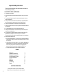
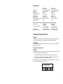
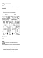
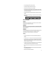
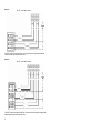
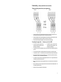
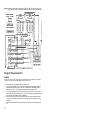
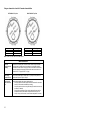
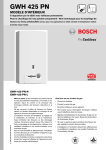
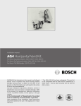
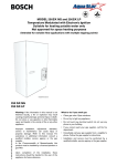
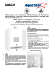
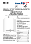
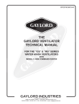
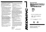
Bosch Thermotechnology Corp.
50 Wentworth Avenue, Londonderry, NH 03053 - 866-642-3198
Important Safety Instructions
When using this electrical equipment, basic safety precautions should always be
followed, including the following:
1. READ AND FOLLOW ALL INSTRUCTIONS.
2.
This appliance must be grounded.
3.
Disconnect this product from the electrical supply before cleaning, servicing or removing the
cover.
4.
To reduce the risk of injury, close supervision is necessary when the product is used near
children or elderly persons.
5.
Warning: Mount the unit onto a flat section of wall, well away from any potential splashes of
water or spray and away from areas where direct moist or wet contact could occur.
6.
Warning: Do not install the heater in a location where it may be subject to freezing.
7.
Warning: Do not install a check valve or any other type of back flow preventer within ten feet of
the cold water inlet.
8.
The electrical installation must conform to current National Electrical Codes.
9.
Warning: Do not switch the heater on if you suspect that it may be frozen. Wait until you are
sure that it has completely thawed out.
10. The Powerstream Pro is designed to heat potable cold water for domestic purposes. The
maximum inlet water temperature it can handle is 86 degrees F. Contact Bosch
Thermotechnology Corp. before specifying or installing the appliance in any other application.
11. Additional Canadian safety instructions:
a) As per the Canadian Electrical Code, C22.1-02 Section 26-744, an auxiliary terminal block
must be fitted to the unit before connecting to the electrical supply (Kit Part N° “AE Canada
Kit”). (See Page 7).
b) A green terminal (or a wire connector marked “G,” “GR,” “GROUND” or “GROUNDING”) is
provided within the control. To reduce the risk of electrical shock, connect this terminal or
connector to the grounding terminal of the electrical service of supply panel with a
continuous copper wire in accordance with the Canadian Electrical Code, Part I.
c) This product shall be protected by a Class A ground fault circuit interrupter.
Contents
Specifications
Installing the Powerstream Pro
Starting up the Powerstream Pro
How the Powerstream Pro works
Using the Powerstream Pro
Spare Parts
Maintenance
Troubleshooting
Warranty
3
3
8
9
10
11
11
12
15
SAVE THESE INSTRUCTIONS
Keep this guide in a safe place once your unit has been installed.
You may need to refer to it for general instructions or future maintenance.
2
Specifications
Voltage supply
Amperage
Maximum output
Temperature control range
Pressure range
Minimum flow rate
Maximum flow rate
Dimensions (excl. water couplers)
Weight (without water)
RP17PT Unit
RP27PT Unit
2 x 240V AC (Canada 240VAC)
2 x 40 A (Canada 80 A)
17.25 kW
95°F to 131°F
15 psi to 150 psi
0.6 US gal / min
See Graph 1, Page 8
15½” H x 151/4 ” W x 4½” D
20 lbs
3 x 240V AC (Canada 240VAC)
3 x 40 A (Canada 120 A)
26.85kW
95°F to 131°F
15 psi to 150 psi
0.8 US gal / min
See Graph 1, Page 8
15½” H x 151/ 4” W x 4½” D
22 lbs
Note: The unit will work at lower supply voltages but the following changes will apply:
Maximum output
15kW at 220V
22.5kW at 220V
13kW at 208V
20kW at 208V
Temperature control range
87°F to 116°F at 220V
87°F to 116°F at 220V
82°F to 108°F at 208V
82°F to 108°F at 208V
Maximum flow rate
84% of maximum at 220V
84% of maximum at 220V
(refer to Graph 1, Page 8)
75% of maximum at 208V
75% of maximum at 208V
Installing the Powerstream Pro
WARNING:
If water supply has a high mineral content, a water softening system is strongly recommended. Damage
to the water heater resulting from scale or hard minerals will not be covered under warranty.
DISCLAIMER:
In the Commonwealth of Massachusetts a licensed plumber or electrician must perform the installation.
(Approval number: P1-09-25).
Locating the Powerstream Pro
WARNING:
Do not install the water heater in an area where there is a chance of freezing. Damage to the water heater
as a result of freezing will not be covered under warranty.
•
If being used in a public place, locate the heater out of easy reach to discourage vandalism.
•
Mount the unit onto a flat section of wall, well away from any potential splashes of water or spray
and away from areas where direct moist or wet contact could occur.
Should it be necessary to service the Powerstream Pro, observe the following clearances. These are not
required clearances, but would facilitate any service work.
Recommended minimum
clearances for servicing
Top
Sides
12”
0”
Bottom
Front
6”
12”
3
Mounting the Powerstream Pro
WARNING:
The heater must only be installed in the orientation shown in Diagram 1 i.e., mounted in a vertical position
with the water fittings located at the bottom of the heater. Under no circumstances should the heater
be mounted differently.
•
Undo the retaining screws on the front cover and take the cover off the heater. Hold the back plate
in position against the wall and mark the four mounting holes
•
Drill the holes and secure the heater using the four wood screws supplied.
Diagram 1
RP17PT Unit
RP27PT Unit
Water Connections
WARNING:
Do not install a non-return check valve within 10 feet of the inlet.
WARNING:
Do not apply heat or solder to connections or pipe if they are already connected to the unit.
DISCLAIMER:
In the Commonwealth of Massachusetts a pressure relief valve shall be installed on the cold water side by
a licensed plumber. (MGL 142 Section 19, Approval number P1-09-25)
•
The heater must be connected directly to the main cold water supply and not to pre-heated water.
(The inlet water temperature must not be greater than 86°F.)
•
The heater must be installed with shutoff valves on both the inlet and outlet connections.
•
It is recommended that you use ¾ inch or ½ inch copper or high-pressure flex connections.
4
•
Do not use plastic piping within 3 feet on either side of heater.
•
Use Teflon tape for sealing pipe threads. Do NOT use pipe dope.
•
Rem ember to keep the hot water pipe runs as short as possible.
•
After the heater has been plumbed, and before you wire it, flush it with water to remove any debris
or loose particles. Heater must be full of water and air purged before power is turned on. Failure to
do so may make the heater inoperable.
•
The inlet and outlet connections are clearly marked on the heater. They each have a ¾ inch NPT
connector.
•
Check the pressure of the main water supply. To operate correctly, the heater needs the following
running pressures:
Recommended water pressures
Min water pressure 15 psi (1 Bar)
Max water pressure
150 psi (10 Bar)
Electrical connections
WARNING
The unit must be wired by a qualified electrician, in accordance with the current version of the National
Electrical Code US) or Canadian Electric Code (Canada).
IMPORTANT
When the heater is not within sight of the electrical circuit breakers, a circuit breaker lockout or additional
local means of disconnection for all non-grounded conductors must be provided that is within sight of the
appliance. (Ref NEC 422.31.)
IMPORTANT
As per the Canadian Electrical Code, C22.1-02 Section 26-744, an auxiliary terminal block must be fitted
to the heater before connecting to the electrical supply. This is available as a kit from Bosch
Thermotechnology Corp. Part Number “AE Canada Kit”. (Contact 866-642 - 3198).
US wiring
•
The minimum recommended wire size is 8 AWG. (The terminal block will accept cables up to 6
AWG size.)
•
The cable entry is via the 1 ¼ inch cable entry hole on the bottom right hand edge of the back plate.
•
Strip back the insulation on the power wires about ½ inch. Connect the live wires to the terminals
marked “L1” and “L2.” There are two pairs of live wires in the RP17PT and three pairs of live wires in
the RP27PT. (See Diagrams 2 or 3 on page 6).
•
Any insulation on the ground wires should be stripped back about ¾ inch. The ground leads must be
connected to the pillar terminal marked “GR”. (See Diagrams 2 and 3, Page 6).
•
Make sure the terminal block screws are tightened securely. Loose connections can cause wires to
heat up.
•
Make sure that the ground wires are wrapped around its terminal stud and into the saddle washer.
The nut should be tightened securely.
•
Attach the front cover and tighten the retaining screws.
5
Diagram 2
RP17PT Terminal Block Connection
The RP17PT requires two independent 240V AC circuits protected by two separate and independent
double pole breakers (as shown) rated at 40 A each.
Diagram 3
RP27PT Terminal Block Connection
The RP27PT requires three independent 240V AC circuits protected by three separate and independent
double pole breakers (as shown) rated at 40 A each.
6
Canada wiring – auxiliary terminal block and connections
Fitting the auxiliary terminal block (see diagram below).
RP17PT
RP27PT
NOT
FOR
U.S.A.
•
Connect the red wires from the left hand terminal of the new block to the L1 terminals in the unit.
(There are two red wires required in the RP17PT and three in the RP27PT).
•
Connect the blue wires from the right hand terminal of the new block to the L2 terminals in the unit.
(There are two blue wires required in the RP17PT and three in the RP27PT).
•
Push and click the auxiliary terminal block onto the louvered rail in the backplate.
Connecting the supply cable - Canada only - not for the USA.
•
The RP17PT requires an 80A 240V AC
single phase supply protected by an 80A
double pole circuit breaker.
•
•
The power cable size and the installation must be in accordance with the Canadian Electrical Code,
C22.1-02.
•
The incoming hole diameter on auxiliary terminal block can accept up to 1/0 AWG size cables.
•
The cable entry is via the 1 ¼ inch cable entry hole on the bottom right hand edge of the backplate.
•
Strip back the insulation on the power wires about ½ inch. Connect the ungrounded conductors to
the terminals “L1” and “L2” on the auxiliary terminal block.
•
Any insulation on the ground wire should be stripped back about ¾ inch. The ground lead must be
connected to the pillar terminal marked “GR.”
•
Make sure the terminal block screws are tightened securely. Loose connections can cause wires to
heat up.
•
Make sure that the ground wire is wrapped around its terminal stud and into the saddle washer. The
nut should be tightened securely.
•
Attach the front cover and tighten the retaining screws.
The RP27PT requires a 120A 240V AC
single phase supply protected by a 120A
double pole circuit breaker.
7
Starting up the Powerstream Pro
Checking for leaks and purging air
•
Verify all circuit breakers supplying power to the water heater are turned off.
•
Open all hot water taps supplied by the water heater and inspect all water connections for leaks.
•
With all hot water taps still open, inspect each tap to ensure all air in the lines has been purged out.
•
With the air purged and taps still flowing, turn on all circuit breakers supplying the water heater.
•
Close all hot water taps and proceed to the next section.
Adjusting the temperature dial
•
The temperature adjustment is made using the dial on the bottom edge of the unit. The adjustment
is between approximately 95°F and 135°F. Turning the dial clockwise increases the temperature
setting as indicated by the marking on the unit.
Adjusting the flow
•
Open fully both inlet and outlet shut-off valves at the heater, then :
•
Turn on fully the highest flowing hot water faucet (e.g., bathtub) served by the water heater.
•
Adjust the outlet shut-off valve until the water flow rate from the hot faucet corresponds to the value
given in Graph 1 below.
Graph 1
8
For example:
•
For the RP17PT unit, using the outlet ball valve, ensure the flow rate does not exceed 2.3 gallons /
minute.
•
For the RP27PT unit, using the outlet ball valve, ensure the flow rate does not exceed 3.5 gallons /
minute.
Note: These figures are based on an inlet water temperature of 55°F and a supply voltage of 240
volts. If the inlet water temperature is lower than 55°F, or if the supply voltage is less than 240 volts,
then the outlet temperature will be lower than what is shown in Graph 1. If a higher outlet water
temperature is desired, then reduce the flow rate and/or supply the unit with 240 volts.
IMPORTANT
Before leaving the site, the installer should demonstrate the unit to the user and give them this guide.
How the Powerstream Pro works
•
The Powerstream Pro heats water continuously as it flows through the heater modules.
•
The electronic control PCB monitors the flow rate and the incoming water temperature and then
switches on the required number of heater elements to reach the temperature set by the adjustment
dial.
•
As the flow rate or the incoming water temperature changes, the electronic control adjusts the
number of heater elements used so that the outlet temperature is maintained.
•
The outlet water temperature can change slightly as the flow rate changes due to the steps in power
as different heater elements are switched on and off.
•
The outlet water temperature can also vary if the maximum flow rate is exceeded (see Graph 1) or if
the supply voltage changes.
•
Each heater module is protected by an electro-mechanical therm al cut-out. If the temperature of any
of the heater modules gets too high, then the cut-out will trip and cut the power to that heater
module. If the cut-out trips, it must be reset while the circuit breakers are off. If you are not
comfortable or qualified to perform this task, consult the original installer or a licensed electrician.
This cut-out will only trip in exceptional circumstances.
•
The RP17PT unit is supplied from two independent voltage supplies and the RP27PT unit from three
independent voltage supplies. (In Canada the unit has just one voltage supply).
•
Depending on the region of the country, the temperature of the water supply can vary between 40°F
in winter to 70°F in summer, with an average of 55°F.
9
Diagram 4: Internal wiring schematic for single phase RP27PT unit. (RP17PT does not have Elt 5 & 6
fitted and uses two supplies). (In Canada an auxiliary terminal block is fitted during installation).
Using the Powerstream Pro
WARNING
Do not use the unit if you think it may be frozen, as this could result in serious damage to the unit. Wait
until you are sure that it has completely thawed out before you switch it on.
•
•
•
•
•
10
Check that the power is switched on at the circuit breaker panel.
Turn on the hot water faucet FULLY. The hot water temperature can be changed by adjusting the
temperature dial on the bottom surface of the unit. (The dial adjusts the temperature typically
between 95°F and 131°F. The factory sets the temperature dial at the lowest position.)
There are internal safety thermal cut-outs which will trip if the unit overheats. If the cut-out trips, it
must be reset while the circuit breakers are off. If you are not comfortable or qualified to perform this
task, consult the original installer or a licensed electrician.
If the unit has been used recently, run the water through for a few seconds to let the temperature
cool down. You may initially get a short burst of very hot water that was in the plumbing lines from
previous use.
If a second outlet connected to the unit is also turned on, the hot water will be shared between the
two.
Spare Parts
Part
Number
93 793770
93 793771
93 793813
93 793773
93 793842
93 793774
93 793775
93 793776
93 793843
93 793844
93 793779
93 793845
93 793846
93 793784
93 793847
93 793848
93 793849
93 793850
Description
(Refer to Diagram 1, Page 4)
4 way term. block (for RP17PT)
6 way term. block (for RP27PT)
Front cover (grey)
Thermal cut-out (RP17PT)
Double pole cut-out (RP27PT)
Flow transducer
PCB enclosure (lid)
PCB enclosure (base)
Control PCB (for RP17PT)
Control PCB (for RP27PT)
Adjustment knob
O Ring set
Fixing screws for heater flange
¾” Inlet filter screen
Heater element assembly 1 (RP17PT)
Heater element assembly 2 (RP17PT)
Heater element assembly 1 (RP27PT)
Heater element assembly 2 (RP27PT)
For further information ask your
local dealer.
FOR SERVICE AND
INSTALLATION QUESTIONS
CALL:
Tel: 866-642-3198
Fax: 603-552-1681
Bosch Thermotechnology
Corporation
Bosch Thermotechnology Corp.
50 Wentworth Avenue
Londonderry, NH 03053
Phone 866 -642-3198
Fax
603-552-1681
www.boschpro.com
[email protected]
Maintenance
Check inlet water filter screen once a year
•
Shut off the installer supplied cold water isolation valve to the heater. If one is not installed, install
before proceeding.
•
Open nearest hot water tap to relieve pressure in the plumbing lines.
•
Position a bucket under the cold water inlet connection of the heater to catch any water that may
drain.
•
Disconnect the cold water plumbing connection from the inlet (bottom right of heater) to access
filter screen (See Diagram 1, Page 4).
•
Rem ove filter, clean with water and inspect for damage. If the filter is at all damaged, it should be
replaced.
•
•
•
•
Replace the filter into the inlet housing
DO NOT clear the filter by back flushing.
•
NEVER use an air line to blow out the heater (the flow transducer will be permanently damaged).
DO NOT leave the filter out.
DO NOT remove the flow regulator (located behind the filter).
11
Troubleshooting
WARNING
Always switch off the electricity supply to the unit before you remove the cover.
IMPORTANT:
If you are unable to perform the tasks listed below, or need additional assistance please contact your
original installer/licensed electrician.
Cold water only – Neon light off
Flow rate is too
low
Verify the flow rate out of fixture is at or above the minimum activation rate
required for the unit to activate. (Activation rates: AE115 = 0.6 GPM, AE125 = 0.8
GPM).
The water supply
is connected to
the outlet of the
unit
Verify plumbing connections are correct (See Diagram 1, Page 4). Reconnect the
water supply to the inlet of the unit (marked blue).
Plumbing
crossover
To test for a plumbing crossover, turn off power supply to the heater. Close
installer supplied cold water shut off valve (if none installed, install before
proceeding). Open all hot water taps supplied by the heater. Wait 5 minutes and
check all taps. Any water running is a sign of a plumbing crossover. Consult a
local plumber or service person for help in correcting a plumbing crossover. To
return the heater to service, reinstall cover, open the inlet water supply to the
heater and open all hot water taps. Let all taps run until there is no air coming out
of the fixtures. Shut off all hot water taps. Turn power supply on to the heater.
Return heater to service. (This procedure will prevent the heating elements from
burning out).
The flow
transducer is not
spinning
Turn off the power supply to the heater and rem ove the cover. Observe if the flow
transducer "spins" when the water is turned on. Please note the flow transducer
spins at a high speed and can appear to be stopped when actually spinning. It is
recommended to observe the flow transducer without water flowing, then turn on a
hot water tap while observing the flow transducer. If the flow transducer is not
spinning, remove and flush flow transducer, noting the Do's and Dont's on Page 11.
See the technical support section of www.boschpro.com for more detailed
instruction on removing the flow transducer.
One or more of the
heating module
thermal cut-outs
has tripped
Turn off the power to the heater, remove the cover and locate thermal cutouts on
the top of each heating module. Try resetting each cutout by pushing the reset
button located in the center of the cutout. Determine and fix the cause of the
overheating. Obstructions in the water path can restrict the flow of water through
the heater causing it to overheat. Verify the heater’s inlet filter screen and all
outlets served by the heater are clear of debris. Ensure the heater is not being fed
preheated water. This water heater is designed for a cold water supply only. If
thermal cut out does not reset, check for continuity through each cutout (less than
0.5 Ohms). If any cutout reads more than 0.5 Ohms or open, then it may be
defective and should be replaced.
No electricity at
the heater or one
of the supplies has
failed
Have a licensed electrician verify proper wiring and adequate voltage on the
terminal block inside the water heater. See the “Electrical connections” section on
Page 5 of this manual.
12
Water too cold – Neon light on
Temperature dial
is turned too low
Turn the temperature dial located on the bottom of the water heater clockwise for
hotter temperatures. Refer to Graph 1 for outlet temperature vs. flow rate vari ance.
Water flow is too
high
Adjust water flow to stay within the water heater’s specifications. See Graph 1 on
Page 8 of this manual.
One or more of the
heating module
thermal cut-outs
has tripped
Shut off the power to the unit, remove the cover and locate thermal cutouts on the
top of each heating module. Try resetting each cutout by pushing the reset button
located in the center of the cutout. Determine and fix the cause of the overheating.
Obstructions in the water path can restrict the flow of water through the heater
causing it to overheat. Verify the heater’s inlet filter screen and all outlets served
by the heater are clear of debris. Ensure the heater is not being fed preheated
water. This water heater is designed for a cold water feed only. If thermal cut out
does not reset, check for continuity through each cutout (Less than 0.5 Ohms). If
any cutout reads more than 0.5 Ohms or open, then it may be defective and
should be replaced.
The power supply
voltage has
dropped
This is likely an issue with the incoming power supply. Have a qualified electrician
measure voltage on the water heater’s terminal block while operating at maximum
flow and maximum temperature setting. The RP17PT / RP27PT models are rated
for 240V and will also operate at 220V or 208V with reduced output. The output
will vary in accordance with the following ratios:
Volts
Output Ratio
208
0.75
220
0.84
240
1.0
The inlet water
temperature is too
cold
Verify the heater is sized appropriately for it’s geographic location. Turn
temperature knob located on the bottom of the water all the way clockwise for
maximum temperature setting. Ensure flow rates are within the heater’s
specifications. Refer to Graph 1 on Page 8 of the manual. Use of an isolation
valve on the hot water outlet to control flow rate is recommended.
One of the power
supplies is not on
Have a licensed electrician verify adequate voltage on the terminal block inside
the water heater. Verify circuit breakers serving the heater are not tripped. See
the “Electrical connections” section on Page 5 of this manual.
Premature element
failure
Shut off power to the unit and remove cover. Use an ohmmeter to verify correct
resistance on each element. If readings are different than listed specifications on
Page 14, contact Technical Support (866) 642-3198 for further instruction.
13
Using an ohmmeter to check for Premature element failure
LEFT MODULE Top View
Meter probes
Outer to Outer
Middle to Middle
Inner to Inner
RIGHT MODULE Top View
Ohm Reading
10.5 ± 0.5 Ohms
11.5 ± 0.5 Ohms
15.0 ± 1 Ohms
Meter probes
Outer to Outer
Middle to Middle
Inner to Inner
Ohm Reading
10.5 ± 0.5 Ohms
11.5 ± 0.5 Ohms
21.0 ± 1 Ohms
Note: On RP17PT model, there is no middle element.
Water flow too low
There are
restrictions in the
plumbing
Obstructions in the water path can restrict the flow of water through the heater.
Verify the heater’s inlet filter screen, faucet aerators, showerheads and whole
house filters are clear of debris. Verify proper flow on the outlet side of the heater
with the hot water pipe disconnected. Maximum flow rates for each unit are as
follows. RP17PT = 2.3gpm, RP27PT = 3.5gpm.
Water supply
pressure too low
Verify incoming water supply is at least 30psi. For people on well systems, the
recommended pressure range is 30-50psi.
Outlet shut-off
valves are set too
low
Adjust installer supplied outlet valve as described below:
•
Completely open both installer supplied inlet and outlet shut-off valves at the
heater. (if none installed, install before proceeding)
•
Completely open hot water on the highest flowing hot water fixture served by
the heater (i.e. bathtub).
•
Slowly close the outlet shut-off valve, slowing the water flow rate until the
temperature at the hot water faucet corresponds to the values given on
Graph 1 on Page 8 of the manual, or desired water temperature is reached.
14
Water Temperature Too Hot
Temperature dial
set too high
Turn the temperature knob located on the bottom of the water heater
counterclockwise for cooler temperatures.
There are
restrictions in the
plumbing
Obstructions in the water path can restrict the flow of water through the heater
causing overheating. Verify the heater’s inlet filter screen, faucet aerators,
showerheads and whole house filters are clear of debris. Verify proper flow on the
outlet side of the heater with the hot water pipe disconnected. Opening hot water
isolation valve fully may be necessary. Maximum flow rates for each unit are as
follows. RP17PT - 2.3gpm, RP27PT - 3.5gpm.
Inlet water
temperature is too
warm
Verify the heater is being feed with cold water only. This water heater is not
designed for preheated water or recirculation applications. Increase flow rate
where ever possible. Replacing low flow showerheads and aerators with higher
flowing (GPM) ones may be necessary.
Cold mix, heater
deactivates
If inlet water temperature is over 70°F, water may be very hot out of the tap. This
requires a lot of cold water to be added in order to get a usable hot water
temperature. The addition of too much cold water will overpower hot water
demand from the water heater. This slows the flow within the water heater,
decreasing it below the activation point, which shuts off the heater. The end result
is nothing but cold water coming out of the outlet. Increase the fl ow rate by
cleaning or replacing fixtures and lower the setting on the temperature adjustment
knob. See service bulletin TWH-E2-04 at www.boschhotwater.com for further
troubleshooting on this symptom.
Fluctuating water
pressure
If the water pressure in the home is erratic and the water flow is not consistent
while a tap is opened, then the temperature of hot water will fluctuate. The
minimum water pressure for the home should be 30psi or greater. For people on
well systems the minimum pressure range is 30-50psi. The use of a pressure
reducing/regulating valve is an effective way to maintain constant water pressure
to the water heater. Watts brand 25AUB- ¾” or N35B-¾” pressure
reducing/regulating valves or equivalent is suggested.
Changing flow rate
Major changes in flow rate can adversely affect the output water temperature of
the heater. Increases from one major fixture running to multiple fixtures running at
one time can cause the temperature to fluctuate. Stay within the heater’s
specifications. See Graph 1 on page 8.
Water Temperature Fluctuates
Powerstream Pro
LIMITED 10 YEAR WARRANTY
COVERAGE
BOSCH THERMOTECHNOLOGY CORP. guarantees this water heater to the original owner of the water
heater at the original installation location against defects in material and workm anship for the periods
specified below.
WARRANTY PERIOD
1.
The Heating Modules – If the original heating modules leak or fail within ten (10) years from the date
of original installation of the water heater because of a defect in material or workmanship, Bosch
Thermotechnology Corp. will furnish to such an owner a replacem ent heater of the then-prevailing
(Continued…)
15
(…Continued)
comparable model. However, if the water heater is installed in other than a single family dwelling this
heating modules warranty is limited to two (2) years from the date of original installation and operation.
Note : Damage caused by exposure to freezing conditions is not covered by the warranty.
Note : Damage caused by scale formation is not covered by the warranty.
2.
3.
Any Component Part Other Than the Heating Modules – If any other component part (other than the
heating modules) proves to be defective in material or workmanship within one (1) year from the
date of original installation of the water heater, Bosch Thermotechnology Corp. will furnish the owner
with a replacement of the defective part(s).
Verification of Date of Original Installation – When owner cannot verify or document the original date
of installation, the warranty period begins on the date of manufacture marked on the tag affixed to
the water heater.
EXCLUSIONS
1.
THIS LIMITED WARRANTY SHALL BE THE EXCLUSIVE WARRANTY MADE BY THE
MANUFACTURER AND IS MADE IN LIEU OF ALL OTHER WARRANTIES, EXPRESSED OR
IMPLIED (WHETHER WRITTEN OR ORAL), INCLUDING, BUT NOT LIMITED TO, WARRANTIES
OF MERCHANTABILITY AND FITNESS FOR A PARTICULAR PURPOSE.
2.
Manufacturer shall not be liable for incidental, consequential, special or contingent damages or
expenses arising, directly or indirectly, from any defect in the water heater or the use of the water
heater.
3.
Manufacturer shall not be liable for any water damage arising, directly or indirectly, from any defect
in the water heater component part(s) or from its use.
4.
Manufacturer shall not be liable under this warranty if:
a)
The water heater or any of its component parts has been subject to misuse, alteration, neglect
or accident, or;
b)
The water heater has not been installed in accordance with the applicable local plumbing
and/or building code(s) and/or regulation(s), or;
c)
The water heater has not been installed in accordance with the printed manufacturer’s
instructions, or;
d)
The water heater is not continuously supplied with potable water.
5.
The owner and not the manufacturer or his representative shall be liable for and shall pay for all field
damages for labor or other expenses incurred in the removal and/or repair of the product or any
expense incurred by the owner in order to repair the product.
SOME STATES DO NOT ALLOW THE EXCLUSION OR LIMITATION OF INCIDENTAL OR
CONSEQUENTIAL DAMAGES, SO THE ABOVE LIMITATION OR EXCLUSION MAY NOT APPLY TO
YOU. THIS WARRANTY GIVES YOU SPECIFIC LEGAL RIGHTS AND YOU MAY ALSO HAVE
OTHERS.
IMPORTANT: OWNER SHALL KEEP THIS CERTIFICATE
NOTE:
A water heater must be installed in such a manner that if it should leak, the resulting flow of
water will not cause damage to the area in which it is installed.
The person who initially installed the unit is the best one to contact for help.
You can also call Bosch Thermotechnology Corp. at 866-642-3198. Please have this guide, model
number, serial number and date of insta llation with you when you call.
Bosch Thermotechnology
Bosch Thermotechnology Corp.
50 Wentworth Avenue
Londonderry NH 03053
Tel: 866-642-3198
Fax: 603-552- 1681
Corportation
www.boschpro.com
06.17.08
© 2008 Bosch Thermotechnology Corp.
555-2028-11G
Londonderry, NH all rights reserved