1
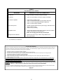
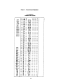
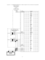
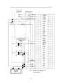
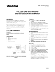
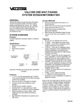
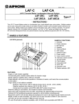
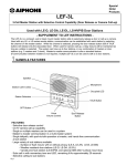
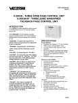
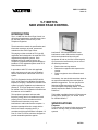
VSP-V-1109RTVA Issue 11 V-1109RTVA NINE ZONE PAGE CONTROL INTRODUCTION The V-1109RTVA, Nine Zone Page Control, is a dial select microprocessor controlled page unit to be used with PABX, Electronic Key or 1A2 Telephone Equipment. These instructions contain the specifications and information necessary to install, operate and maintain the Nine Zone Page Control. interference. If this equipment does cause interference to radio and television reception, which can be determined by turning the equipment off and on, the user is encouraged to try to correct the interference by one or more of the following measures: This paging unit has received an FCC type KX registration and is designed to be used with FCC registered key telephone systems. Such installations may be made by Valcom, Inc., Telephone Companies and registered telephone installers of FCC registered systems under FCC Rules Section 68.215. In accordance with FCC rules with applicable tariffs, this intercom unit may only be installed with the authorization of the owner of the host system. Reorient the receiving antenna Relocate the equipment with respect to the receiver Plug the equipment into a different branch circuit The FCC Registration Number BAF9I7-69358KX-N, will be listed in the affidavits filed with the telephone company; it will also be recorded in the system log kept by installation and maintenance personnel. The local Telephone Company is to be notified of the FCC Registration Number when this intercom unit is installed. If necessary, the user should consult the dealer or an experienced radio/television technician for additional suggestions. The user may find the following booklet prepared by the Federal Communications Commission helpful: "How to Identify and Resolve Radio-TV Interference Problems." This equipment generates and uses radio frequency energy and if not installed and used properly, that is in strict accordance with the manufacturer's instructions, may cause interference to radio and television reception. It This booklet is available from the US Government printing office, Washington, DC 20402. Stock No. 004-000-00345-4. has been tested and found to comply with the limits for a Class B computing device, in accordance with the specifications in Subpart J of Part 15 of the FCC Rules, which are designed to provide reasonable protection against To provide nine (9) zones of voice announce with all call to 1A2 Key, E-Key or PABX telephone systems. SPECIFICATIONS Purpose 1 947109 TABLE 1 Talk Battery -21.5 to -26VDC 60mA Signal Battery -21.5 to -25VDC 250mA Lamp Battery 9 to 11VAC 45mA/Lamp Note: Remember when working with telephone equipment that BATTERY is NEGATIVE and GROUND is POSITIVE. Applications 1A2 key systems Electronic key system line key position PABX loop start trunk position Features 9 page zones Built in preamplifier for one-way page operation Dial tone Ringback tone Combined rotary and tone dialing Background music input and amplifier Built-in all call Single digit dialing Off hook speaker inhibit (1A2) Off hook single digit redial (push asterisk key) Electrical Characteristics The operating parameters of the page control are listed in Table 2. TABLE 2 Parameters Capacity Working Limits Input impedance Tip and Ring: Max cable length to speaker: Dial Pulses: The capacity of the V-1109RTVA is 9 zones and all call One talkpath The maximum number of one-way speaker/amplifier speaker assemblies is 40 per zone unless a V-1094A expander is used. Tone Signals: Frequency Bandwidth: Twist: Detect: Interdigital Time: Numbering Plan The dialing codes are 1-9, 0 for all call. Additional Materials Required At the time of installation, the installer should provide the following materials: -24VDC filtered power supply (if existing supply is not adequate) 66 type connecting block 25 pair cable with a female amphenol connector on one end Twisted pair cross-connect wire Environmental Temperature: Humidity: 600 Ohms 5000 feet audio 8-12pps 60-40 break ratio +/- 10% Industry Standard 3% 6dB 40ms 40ms 0 to 50o C 0 to 85% (non-precipitating) INSTALLATION This section covers the installation procedures for the Valcom V-1109RTVA only. Consult other equipment instructions if additional equipment is used. Dimensions/Weight 7.10"H x 5.90"W x 2.10"D (18.03cm H x 14.99cm W x 5.33cm D) 2.7 lbs. (1.23 kg) Precautions All precautions have been taken at the factory to insure that the equipment functions properly. To insure proper operation and to prevent equipment damage, please observe the following: Power Requirements The Valcom V-1109RTVA requires -24VDC talk battery and -24VDC signal battery. The current consumption and voltage range is shown in Table 1. 2 NOTE: When the V-1109RTVA is connected to a 1A2 Key System, connect W/O to Lamp Battery or Ground. See Figure 3. Unplug the power supply before making any connections to the control unit. Do not locate the control unit closer than 18 inches or further than five feet from power supply. Do not use a lamp tester to check signals; use a voltmeter. A lamp tester when first applied is a short circuit to electronic circuits. Do not apply power to the control unit until all connections have been double checked. NOTE: For "Meet Me Page" on 1A2, connect A-Leads from spare button using 10K Ohm resistors in series with each A-Lead. The other side of resistors are connected to the BK/G (inhibit) of V-1109RTHF. Refer to Figure 3 for connections. Mounting Power Connections Mount the unit in a vacant space in an equipment cabinet, rack or key system cabinet, allowing enough room at the rear of the unit to plug in an amphenol connector. Mount a 66B type punchdown block near the unit and label it per Figure 1. Cabling A 25 pair cable with a female connector should be ran from the unit to the connection block. The cable should be terminated on the connection block in standard color code order. Verify that the connections are correct prior to plugging the other end of the cable into the V-1109RTVA Page Unit. The V-1109RTVA is designed to use -24VDC battery. Connect the V/BR lead to Talk Ground. Connect the BR/V lead to Talk Battery (-24VDC filtered). Connect the V/S lead to Signal Ground. Connect the S/V lead to Signal Battery (-24VDC unfiltered). Speaker Connections The outputs for paging zones start at the BK/BR pair (zone 1) through the V/O pair (zone 9). Refer to Figure 3 for typical speaker connections using Valcom one-way amplified speaker assemblies. Connections to PABX System Page and Music Level Set-up The V-1109RTVA may be accessed by connecting the W/BL and BL/W to the Tip and Ring respectively of a Loop Start Trunk Circuit. Refer to Figure 2 for connections. The V-1109RTVA has volume controls for the following functions: Connections to Electronic Key Systems The V-1109RTVA may be accessed by a C.O. line position of an Electronic Key System by connecting the W/BL, BL/W of the V-1109RTVA to a spare line position of the Electronic Key. This line position must be equipped with a trunk card. Refer to Figure 2 for connections. Control Set-Up: 1. Master Page Control: This control sets the level of the page out of the page control unit. The control should be rotated clockwise to about 50% of its travel. After setting control, the individual speaker volume controls should be set to the desired level. 2. All Call Level: The All call level should be set to produce the same audio level as the phone to speaker page control. THIS ADJUSTMENT SHOULD BE MADE AFTER INDIVIDUAL SPEAKER LEVELS HAVE BEEN SET. Connections to 1A2 Key System The V-1109RTVA may be connected to a spare button of a 1A2 Key Telephone by making the following connections: (A 400 type line card is not needed in this application). Master Page Control - located on back of unit below amphenol connector All Call Master Control - located on front of unit Background music input control Zones 1-5 Background music input control Zones 6-9 W/BL, BL/W of V-1109RTVA to spare button Tip and Ring O/W to Lamp Lead of spare button for lamp connections W/GR to Lamp Ground lead of spare button 3 3. Background Music Levels: There are two volume controls provided for background music adjustments: Zones 1-5. and Zones 6-9. It is important that the two background music controls be used to set the music levels in the system. Adjust these controls after all other system volume levels have been set. THE MUSIC INPUT LEVEL FROM THE MUSIC SOURCE SHOULD BE LIMITED TO 0.25VRMS MAXIMUM. A SOURCE LEVEL GREATER THAN 0.25VRMS WILL RESULT IN PERMANENT DAMAGE TO THE BACKGROUND MUSIC AMPLIFIERS CONTAINED IN THE V-1109RTVA. The music source should be connected to the V/G Pair on the connecting block for the Page Control Unit TECHNICAL ASSISTANCE When trouble is reported, verify that power is being supplied to the unit and there are no broken connections. Be sure that the amphenol is secure in the back of the unit. Check voltages for proper polarity on the crossconnect block. A lineman's test set, several clip leads and a VOM may be necessary to effectively troubleshoot the unit. Table 3 identifies some possible problems and solutions. If a spare unit is available, continue to troubleshoot by substituting the spare unit for the suspected unit. Assistance in troubleshooting is available from the factory. When calling, you should have a VOM and a telephone test set available and call from the job site. Call (540) 563-2000 and press 1 for Technical Support or visit our website at http://www.valcom.com. OPERATION This unit provides multi-zone page access provisions to appropriately interface with the telephone system being used. A preamplifier conditions the audio from the telephone system tip and ring and provides a low impedance low level output to the desired page zone. Valcom equipment is not field repairable. Valcom maintains service facilities in Roanoke, VA. Should repairs be necessary, attach a tag to the unit clearly stating your company name, address, phone number, contact person and the nature of the problem. Send the unit to: Circuit Description When a station user lifts his handset to make a page, the switchhook contacts in the telephone close the tip and ring to form a loop which returns battery back to turn on transistor Q1. Transistor Q1 operates relay and logic circuits to return dial tone and lamp battery to the telephone set. Logic circuits receive dialing information and operate relays and/or circuitry to provide a ringback tone and a one-way connection for the zone selected. Valcom, Inc. Repair and Return Dept. 5614 Hollins Road Roanoke, VA 24019-5056 4 TABLE 3 TROUBLESHOOTING CHART PROBLEMS PROBABLE CAUSES AND CORRECTIONS No side tone Check "A" battery connection, polarity and voltage. No dial tone Check "A" and "B" battery connections, polarity and voltage. No volume to speakers Check phone to speaker control. Check * for audio present at tip, ring input (W/BL, BL/W pair). Check * for audio at signaled speaker pair at 66B block. Check * for audio at input of speaker. Hum heard at phone Possible magnetic interference from power supply - Relocate unit and cables at least 18" away. Check for noisy "A" battery. No speaker cancel Verify ground present at phone side of at least (2) 10K Ohm resistors. Refer to "Connections to 1A2 Key System." NOTE: Do not apply ground directly to inhibit input. Background music distorted Music source level too high. Refer to "Page & Music Level Set Up" procedures. Use lineman's test set (Butt set). VALCOM LIMITED WARRANTY Valcom, Inc. warrants its products only to the original purchaser, for its own use, to be free from defects in materials and workmanship under conditions of normal use and service for a period of one year from the date of shipment. This Limited Warranty obligation shall be limited to the replacement, repair or refund of any such defective device within the warranty period, provided that: 1. inspection by Valcom, Inc. indicates the validity of the claim; 2. the defect is not the result of damage, misuse or negligence after the original shipment; 3. the product has not been altered in any way or repaired by others and that factory sealed units are unopened (a service charge plus parts and labor will be applied to units defaced or physically damaged); 4. freight charges for the return of products to Valcom are prepaid; 5. all units 'out of warranty' are subject to a service charge. The service charge will cover minor repairs (major repairs will be subject to additional charges for parts and labor). This Limited Warranty is in lieu of and excludes all other warranties, expressed or implied and in no event shall Valcom, Inc. be liable for any anticipated profits, consequential damages, loss of time or other losses incurred by the buyer in connection with the purchase, operation, maintenance, installation, removal or use of the product. The maximum liability of Valcom under this warranty is limited to the purchase price of the specific Product covered by the warranty. Disclaimer. Except for the Limited Warranty provided herein, the product is provided “as-is” without any warranty of any kind whatsoever including, without limitation, any WARRANTY OF MERCHANTABILITY, FITNESS FOR A PARTICULAR PURPOSE OR NON-INFRINGEMENT. This warranty specifically excludes damage incurred in shipment. In the event a product is received in damaged condition, the carrier should be notified immediately. Claims for such damage should be filed with the carrier involved in accordance with the F.O.B. point. Headquarters: Valcom, Inc. 5 6 F ig u re 2 - V -1 1 0 9 R T V A C o n n e c tio n s to P A B X L o o p S ta rt T ru n k o r E le c tro n ic K e y S y s te m E L E C T R O N IC K E Y C .O . L IN E P O S IT IO N OR PABX LO O P START TRUNK P O S IT IO N T IP T IP W H /B L R IN G R IN G B L /W H W H /O O /W H W /G R G R /W W /B R B R /W W /S S /W R /B L B L /R R /O O /R R /G G /R R /B R B R /R R /S S /R B K /B L B L /B K B K /O V A L C O M O N E -W A Y O /B K S P E A K E R /A M P L IF IE R B K /G A S S E M B L IE S G /B K R E T R IN G B K /B R SPK1 T IP B R /B K ZONE 1 GND B K /S -2 4 S /B K Y /B L B L /Y Y /O O /Y R IN G Y /G T IP G /Y ZONE 9 GND Y /B R -2 4 B R /Y Y /S S /Y V /B L B L /S RET V /O SPK9 O /Y V /G G /V AG V /B R AB B R /V BG V /S BB S /V - + VALCO M P0W ER SU PPLY 7 F ig u re 3 - 1 A 2 K e y S y s te m C o n n e c tio n s , S p e a k e r C o n n e c tio n s a n d P o w e r C o n n e c tio n s TELEPH O NE IN T E R C O M BUTTO N M U L T IP L E T O A LL P H O N ES T IP R IN G LS L LG T IP R IN G LG L LS ±10VAC LAM P SU PPLY A 10K N o te 1 V A L C O M O N E -W A Y S P E A K E R /A M P L IF IE R A S S E M B L IE S R IN G T IP ZONE 1 GND -2 4 RET SPK1 R IN G T IP GND -2 4 ZO NE 9 RET SPK9 AG AB BG BB - + VALCO M P 0W ER S U P PLY W H /B L B L /W H W H /O O /W H W /G R G R /W W /B R B R /W W /S S /W R /B L B L /R R /O O /R R /G G /R R /B R B R /R R /S S /R B K /B L B L /B K B K /O O /B K B K /G G /B K B K /B R B R /B K B K /S S /B K Y /B L B L /Y Y /O O /Y Y /G G /Y Y /B R B R /Y Y /S S /Y V /B L B L /S V /O O /Y V /G G /V V /B R B R /V V /S S /V N O T E : IN S T A L L 1 0 K R E S IS T O R S IN A L E A D S F O R A L L TELEPHO NES. 8 9